EP4443019A1 - Elektromechanischer aktuator - Google Patents
Elektromechanischer aktuator Download PDFInfo
- Publication number
- EP4443019A1 EP4443019A1 EP24161433.8A EP24161433A EP4443019A1 EP 4443019 A1 EP4443019 A1 EP 4443019A1 EP 24161433 A EP24161433 A EP 24161433A EP 4443019 A1 EP4443019 A1 EP 4443019A1
- Authority
- EP
- European Patent Office
- Prior art keywords
- assembly
- motor
- electromechanical actuator
- distal end
- hollow cylinder
- Prior art date
- Legal status (The legal status is an assumption and is not a legal conclusion. Google has not performed a legal analysis and makes no representation as to the accuracy of the status listed.)
- Granted
Links
Images


Classifications
-
- F—MECHANICAL ENGINEERING; LIGHTING; HEATING; WEAPONS; BLASTING
- F16—ENGINEERING ELEMENTS AND UNITS; GENERAL MEASURES FOR PRODUCING AND MAINTAINING EFFECTIVE FUNCTIONING OF MACHINES OR INSTALLATIONS; THERMAL INSULATION IN GENERAL
- F16H—GEARING
- F16H25/00—Gearings comprising primarily only cams, cam-followers and screw-and-nut mechanisms
- F16H25/18—Gearings comprising primarily only cams, cam-followers and screw-and-nut mechanisms for conveying or interconverting oscillating or reciprocating motions
- F16H25/20—Screw mechanisms
-
- F—MECHANICAL ENGINEERING; LIGHTING; HEATING; WEAPONS; BLASTING
- F16—ENGINEERING ELEMENTS AND UNITS; GENERAL MEASURES FOR PRODUCING AND MAINTAINING EFFECTIVE FUNCTIONING OF MACHINES OR INSTALLATIONS; THERMAL INSULATION IN GENERAL
- F16H—GEARING
- F16H1/00—Toothed gearings for conveying rotary motion
- F16H1/28—Toothed gearings for conveying rotary motion with gears having orbital motion
-
- H—ELECTRICITY
- H02—GENERATION; CONVERSION OR DISTRIBUTION OF ELECTRIC POWER
- H02K—DYNAMO-ELECTRIC MACHINES
- H02K21/00—Synchronous motors having permanent magnets; Synchronous generators having permanent magnets
- H02K21/12—Synchronous motors having permanent magnets; Synchronous generators having permanent magnets with stationary armatures and rotating magnets
- H02K21/14—Synchronous motors having permanent magnets; Synchronous generators having permanent magnets with stationary armatures and rotating magnets with magnets rotating within the armatures
- H02K21/16—Synchronous motors having permanent magnets; Synchronous generators having permanent magnets with stationary armatures and rotating magnets with magnets rotating within the armatures having annular armature cores with salient poles
-
- H—ELECTRICITY
- H02—GENERATION; CONVERSION OR DISTRIBUTION OF ELECTRIC POWER
- H02K—DYNAMO-ELECTRIC MACHINES
- H02K5/00—Casings; Enclosures; Supports
- H02K5/04—Casings or enclosures characterised by the shape, form or construction thereof
- H02K5/16—Means for supporting bearings, e.g. insulating supports or means for fitting bearings in the bearing-shields
- H02K5/173—Means for supporting bearings, e.g. insulating supports or means for fitting bearings in the bearing-shields using bearings with rolling contact, e.g. ball bearings
- H02K5/1737—Means for supporting bearings, e.g. insulating supports or means for fitting bearings in the bearing-shields using bearings with rolling contact, e.g. ball bearings radially supporting the rotor around a fixed spindle; radially supporting the rotor directly
-
- H—ELECTRICITY
- H02—GENERATION; CONVERSION OR DISTRIBUTION OF ELECTRIC POWER
- H02K—DYNAMO-ELECTRIC MACHINES
- H02K7/00—Arrangements for handling mechanical energy structurally associated with dynamo-electric machines, e.g. structural association with mechanical driving motors or auxiliary dynamo-electric machines
- H02K7/06—Means for converting reciprocating motion into rotary motion or vice versa
-
- H—ELECTRICITY
- H02—GENERATION; CONVERSION OR DISTRIBUTION OF ELECTRIC POWER
- H02K—DYNAMO-ELECTRIC MACHINES
- H02K7/00—Arrangements for handling mechanical energy structurally associated with dynamo-electric machines, e.g. structural association with mechanical driving motors or auxiliary dynamo-electric machines
- H02K7/10—Structural association with clutches, brakes, gears, pulleys or mechanical starters
- H02K7/116—Structural association with clutches, brakes, gears, pulleys or mechanical starters with gears
-
- F—MECHANICAL ENGINEERING; LIGHTING; HEATING; WEAPONS; BLASTING
- F16—ENGINEERING ELEMENTS AND UNITS; GENERAL MEASURES FOR PRODUCING AND MAINTAINING EFFECTIVE FUNCTIONING OF MACHINES OR INSTALLATIONS; THERMAL INSULATION IN GENERAL
- F16H—GEARING
- F16H25/00—Gearings comprising primarily only cams, cam-followers and screw-and-nut mechanisms
- F16H25/18—Gearings comprising primarily only cams, cam-followers and screw-and-nut mechanisms for conveying or interconverting oscillating or reciprocating motions
- F16H25/20—Screw mechanisms
- F16H2025/2062—Arrangements for driving the actuator
- F16H2025/2075—Coaxial drive motors
-
- F—MECHANICAL ENGINEERING; LIGHTING; HEATING; WEAPONS; BLASTING
- F16—ENGINEERING ELEMENTS AND UNITS; GENERAL MEASURES FOR PRODUCING AND MAINTAINING EFFECTIVE FUNCTIONING OF MACHINES OR INSTALLATIONS; THERMAL INSULATION IN GENERAL
- F16H—GEARING
- F16H25/00—Gearings comprising primarily only cams, cam-followers and screw-and-nut mechanisms
- F16H25/18—Gearings comprising primarily only cams, cam-followers and screw-and-nut mechanisms for conveying or interconverting oscillating or reciprocating motions
- F16H25/20—Screw mechanisms
- F16H2025/2062—Arrangements for driving the actuator
- F16H2025/2087—Arrangements for driving the actuator using planetary gears
Definitions
- the present disclosure relates to electromechanical actuators.
- Actuators have been in use for several decades and have found applications in various industries such as aerospace, automotive, robotics, manufacturing and so forth.
- the actuators are devices that convert electrical energy into mechanical motion and are used to control the movement of various components in machines and systems.
- an electromechanical actuator is widely used due to its wide application.
- the electromechanical actuator is a device that converts electrical energy into mechanical motion or force.
- the electromechanical actuator consists of an electric motor and a mechanical means that converts the rotational motion of the motor into linear motion or force.
- the electric motor can be a DC motor or an AC motor, and it is controlled by an electronic controller that adjusts the speed of the motor and the direction of the mechanical means.
- the mechanical means include gears, screws, or pistons.
- the electromechanical actuator is preferred over conventional hydraulic or pneumatic actuators because they are more precise, faster, and quieter.
- the electromechanical actuators are typically linear actuators, rotary actuators, and solenoids.
- the linear actuator is used to produce linear motion.
- Linear actuators consist of a motor and an output shaft. When the motor rotates, it drives the output shaft, producing linear motion.
- the linear actuators provide linear motion and are used in applications such as lifting, pushing, or pulling Moreover, the rotary actuators are used to produce rotary motion.
- the rotary actuators consist of a motor, a gear train, and an output shaft. When the motor rotates, it drives the gear train, which in turn rotates the output shaft, producing rotary motion.
- the existing electromechanical actuators have limitations in terms of their ability to produce complex motion patterns and their overall efficiency. Moreover, the existing electromechanical actuator designs are not able to provide higher forces, speeds, and precision. Furthermore, the existing electromechanical actuators are expensive and are difficult to integrate into standard machinery due to their size and weight. Moreover, the actuators have a low force density.
- the existing electromechanical actuators are causing because of their size (length and overall width) challenges, especially when they are fit to places where there is not much space available.
- the actuator is typically quite long, and if the electric motor is aside of the actuator cylinder, then the actuator is typically wide, which is not favourable, because it makes it vulnerable and on the other hand its width may cause problems when it is fitted to places where there is not much space available.
- the present disclosure seeks to provide an electromechanical actuator.
- An aim of the present disclosure is to provide a solution that overcomes at least partially the problems encountered in prior art.
- an electromechanical actuator comprising:
- Embodiments of the present disclosure substantially eliminate or at least partially address the aforementioned problems in the prior art, and enable compact, and efficient electromechanical actuator. Moreover, the electromechanical actuator provides smooth and precise motion with reduced friction and wear and is thereby configured to absorb the loads produced during the operation thereof.
- an underlined number is employed to represent an item over which the underlined number is positioned or an item to which the underlined number is adjacent.
- a non-underlined number relates to an item identified by a line linking the non-underlined number to the item. When a number is non-underlined and accompanied by an associated arrow, the non-underlined number is used to identify a general item at which the arrow is pointing.
- an electromechanical actuator comprising:
- the present disclosure provides the aforementioned electromechanical actuator.
- the electromechanical actuator provides precise and repeatable linear motion and rotational motion with high force capability, making it well-suited for a wide range of applications.
- the use of a screw-nut mechanism, along with the planetary gear assembly, enables high efficiency and torque output, which allows for fast and accurate positioning of loads.
- the electromechanical actuator is compact, which is achieved by the use of the concentric motor assembly and the planetary gear assembly.
- the concentric motor assembly allows for more efficient use of space, and the integration of the planetary gear assembly set eliminates the need for external gearboxes.
- the electromechanical actuator also provides high reliability due to its simple and robust design.
- the use of the pair of motor bearing bearings and the bearing assembly arranged on the motor assembly and the carrier, respectively, provides smooth and precise motion with reduced friction and wear and is thereby configured to absorb the loads produced during the operation of the electromechanical actuator.
- the design of the electromechanical actuator allows for easy assembly, maintenance, and repair.
- the use of cover plates and housing that surrounds the planetary gear assembly and bearing assembly provides protection and containment of the moving parts, while also allowing for easy access for maintenance and repair.
- the modular design of the electromechanical actuator enables easy disassembly and replacement of individual components if required.
- electromechanical actuator refers to a device that is configured to convert electrical energy into mechanical motion.
- the electromechanical actuator is arranged to provide precise and controllable motion when in use.
- the electromechanical actuators convert the rotational force to generate linear motion.
- the electromechanical actuator may also rotate along its axis.
- the electromechanical actuators are configured to provide precise and repeatable motion.
- the electromechanical actuators are capable of providing highly accurate and consistent motion.
- the aforementioned electromechanical actuators are reliable and easy to maintain.
- reciprocating assembly refers to a mechanical component that moves back and forth in a straight-line motion.
- the reciprocating assembly comprises the screw.
- screw refers to an elongated body that has a helical (spiral) ridge or groove, which is designed to mesh with the grooves or threads of a mating component.
- the screw comprises the threaded body portion which is typically a cylindrical section of the screw that extends along its length, and the threads are arranged on an external surface of the screw.
- the screw with the external threaded body portion is screwed into a mating component with internal threads, such as a nut, the two components become mechanically coupled and can be used to generate linear and/or rotational motion.
- the screw threaded body portion can be fabricated from plastic, metal, non-metal, composite, fibre or any combination thereof.
- the screw comprises the distal end integral with threaded body.
- the term "concentrically” as used herein refers that the inner and outer hollow cylinder and the screw are aligned so that they have practically a common longitudinal axis / aligned around a common longitudinal axis.
- the nut is threadably engaged with the threaded body portion of the screw and is arranged to provide a mechanical connection between the nut and the screw.
- the nut may be hexagonal-shaped, circular-shape, square-shaped, rectangular-shaped or any combination thereof with a hole in the centre that is threaded internally.
- the nut may be fabricated from a metal, plastic, composite or any combination thereof.
- the guide is mounted on the nut.
- guide refers to a component that is mounted on the nut of the reciprocating assembly and is configured to provide stability and support to the nut to ensure that the nut moves along a predetermined path or axis during operation.
- the nut is configured to move back and forth along the length of the screw, generating linear motion.
- the guide is mounted on the nut, and it ensures that the nut moves along a predetermined path as it reciprocates along the screw.
- the guide is fabricated from plastic, metal, non-metal, composites, fibres or any combination thereof.
- the guide helps to prevent the nut from deviating from the desired path. This can improve the overall performance of the actuator and make it more reliable in operation.
- the term "cylinder assembly" as used herein refers to a component that is used to provide a mechanical guide for the reciprocating assembly and to help generate the linear motion.
- the cylinder assembly includes the outer hollow cylinder having the proximal end and the distal end opposite to the proximal end, and the inner hollow cylinder having the proximal end and the distal end opposite to the proximal end.
- the inner hollow cylinder is enclosed by the outer hollow cylinder.
- the inner hollow cylinder is configured to receive the screw of the reciprocating assembly through its centre.
- the distal end of the inner hollow cylinder abuts the nut of the reciprocating assembly, such that the inner cylinder moves with the nut as it reciprocates back and forth along the screw.
- the outer hollow cylinder is arranged to control the movement of the inner hollow cylinder in the reciprocating assembly, thereby keeping the inner hollow cylinder aligned and preventing it from wobbling or deviating from its desired path.
- the inner hollow cylinder is designed to work in conjunction with the nut and screw of the reciprocating assembly, to generate the linear motion.
- the guide is configured to fit snugly against the inner surface of the cylinder assembly and help to maintain the alignment of the nut within the cylinder.
- the electromechanical actuator enables a large load to be moved over a predefined distance.
- the electromechanical actuator offers a greater range of control and efficiency and may widely be implemented in automobiles, lifts, cranes, heavy machines, robotic arms, modular beds, modular doors, and so forth.
- the reciprocating movement comprises to-and-fro movement of the inner hollow cylinder with respect to the outer hollow cylinder.
- the movement of the inner hollow cylinder is actuated by the reciprocating assembly.
- the electromechanical actuator comprises the outer hollow cylinder and the inner hollow cylinder that is configured to receive the screw of the reciprocating assembly.
- the screw is rotated, the nut, which is threadably engaged to the screw, moves along the screw's threaded body portion.
- the nut is mounted on the guide, the movement of the nut causes the inner hollow cylinder to move along the axis with respect to the outer hollow cylinder, resulting in the reciprocating movement.
- to-and-fro movement refers to the back-and-forth movement of the inner hollow cylinder as it moves along the length of the screw.
- the back-and-forth movement is characterized by a series of repeated cycles, where the inner hollow cylinder moves outwards from the outer hollow cylinder, and then inwards thereof.
- the said movement is continuous, resulting in the reciprocating motion of the electromechanical actuator that can be harnessed to perform various functions, for example, actuating a valve or a piston in a machine, and so forth.
- the motor assembly in the electromechanical actuator is responsible for providing the rotary motion necessary to generate the linear motion of the electromechanical actuator.
- the motor assembly is an electric motor assembly.
- the electric motor converts electrical energy into mechanical energy.
- the electric motor assembly can be powered by direct current (DC) sources, such as batteries or rectifiers, or by alternating current (AC) sources, such as a power grid, inverters or electrical generators.
- DC direct current
- AC alternating current
- the electric motors produce a linear force or a rotary force i.e., torque intended to rotate the driving part, such as the reciprocating assembly and the cylinder assembly, coupled to it.
- the motor assembly may be selected but not limited to hydraulic motor, gear motor, pneumatic motor and the like.
- the motor stator is a stationary part of the motor assembly.
- the motor stator contains coils of wire.
- the motor rotor is a rotating part of the motor assembly that contains permanent magnets.
- the flange is a disk-shaped component that abuts the motor rotor and provides a mounting point for the planetary gear assembly.
- the pair of motor bearing are designed to support the motor rotor and allow it to rotate smoothly and accurately.
- the motor bearing is a ball bearing, such as a deep-groove ball bearing, self-aligning ball bearing, angular-contact ball bearing, thrust ball bearing and forth.
- the motor bearing is a roller bearing, such as a spherical roller bearing, cylindrical roller bearing, tapered roller bearing, needle roller bearing and so forth.
- the pair of motor bearing is surrounded by the motor rotor and is used to reduce rotational friction and support the motor assembly from radial and axial loads due to the rotation of the motor assembly.
- the bearing while facilitating motion, support both the rotation of the screw and the force applied by the planetary gear assembly.
- the electromechanical actuator further comprises a bearing rest arranged on the distal end of the outer hollow cylinder, the bearing rest supports the pair of motor bearing thereon.
- bearing rest refers to a component that is arranged on the distal end of the outer hollow cylinder to support the pair of motor bearings.
- the bearing rest of the motor assembly help to stabilize the motor rotor as it rotates.
- the arrangement of the bearing rest on the outer hollow cylinder helps to effectively support and ensure the proper functioning of the electromechanical actuator.
- the bearing rest minimizes vibration or wobbling that occurs during the operation of the electromechanical actuator.
- the electromechanical actuator further comprises a first cover plate arranged on the distal end of the outer hollow cylinder and abuts the bearing rest, and a second cover plate opposite to the first cover plate and abuts the housing.
- the first cover plate and the second cover plate are positioned at opposite ends surrounding the motor assembly.
- the first cover plate is arranged on the distal end of the outer hollow cylinder and abuts the bearing rest.
- the first cover plate is used to hold the motor bearing in place and to provide protection and support to the bearing assembly.
- the second cover plate abuts the housing that surrounds the motor assembly from the opposite end. The second cover plate serves to provide additional protection and securely hold the motor assembly thereof.
- the arrangement of the first and second cover plate form a protective outer shell for the electromechanical actuator.
- the motor assembly is a frameless motor with the motor stator arranged between the first cover plates and second cover plates.
- the frameless motor is a type of motor in which the motor stator and motor rotor are not contained within a traditional motor housing or frame.
- the motor stator is mounted to a stationary structure of the electromechanical actuator and the motor rotor is mounted to the screw.
- the motor stator is arranged between the first and second cover plates of the electromechanical actuator, which provides a compact and space-saving design.
- the frameless motor allows a smaller overall size of the motor assembly and thereby maintaining a high torque output.
- the use of the frameless motor allows easier integration of the motor assembly within the electromechanical actuator, as the motor assembly can be mounted directly to the load (such as the reciprocating assembly) without the need for additional mechanical components such as couplings or mounting brackets and the like. Additionally, the frameless design of the motor allows for a reduction in the weight and size of the electromechanical actuator.
- the motor stator is the stationary part of the motor assembly that surrounds the motor rotor.
- the motor stator is composed of the coil housing and the coil arrangement housed within the coil housing.
- the coil housing is a component that houses the coil arrangement.
- the coil arrangement is made of wire wound around a core and is used to create a magnetic field when an electric current is passed through it.
- the coil housing provides physical support for the coil arrangement and protects from external factors such as moisture, dust, and heat.
- the coil housing has openings or vents to facilitate the dissipation of heat generated by the coil arrangement.
- the coil arrangement consists of copper or aluminium wires.
- the motor rotor is composed of the magnet housing and the permanent magnet housed within the magnet housing.
- the magnet housing is a structure that holds and supports the permanent magnet within the motor assembly.
- the magnet housing is made of a ferromagnetic material that enhances the magnetic field produced by the permanent magnet.
- the magnet housing is designed to keep the magnet securely in place from damage or loss of magnetization.
- the magnetic field generated by the motor stator interacts with the magnetic field of the motor rotor, causing the motor rotor to rotate.
- the electromechanical actuator further comprises connecting wire terminals extending from the coil arrangement and through the coil housing.
- the wire terminals are used to connect the motor stator to an external power source.
- the wires are connected to the coil arrangement, which is housed within the coil housing of the motor stator.
- the wire terminals extend through the coil housing, which provides protection to the wires and ensures they are securely held in place.
- the wire terminals enable the motor stator to receive electrical power and convert it into mechanical energy.
- the wire terminals are fabricated from a conductive material such as copper. It will be appreciated that the wire terminals are designed to be durable and withstand the rigorous operating environment of the electromechanical actuator.
- the motor assembly is arranged concentrically at the distal end of the outer hollow cylinder of the cylinder assembly.
- the planetary gear assembly is mounted to the flange of the motor assembly and is operatively arranged in connection with the reciprocating assembly to provide the linear motion.
- the concentric design of the motor assembly helps in reducing the overall size and weight of the electromechanical actuator by integrating the motor assembly with the cylinder assembly.
- the concentric motor assembly makes it easier to install the electromechanical actuator in tight spaces where there is limited space available.
- the motor assembly arranged concentrically with respect to the cylinder assembly helps in the direct transfer of energy from the motor rotor to the load, resulting in higher efficiency.
- the motor assembly may vary depending on the requirements of the electromechanical actuator, such as the required torque or speed of the electromechanical actuator. For example, a high-torque electromechanical actuator may require the motor assembly with a greater motor stator and motor rotor, while a high-speed electromechanical actuator may require the motor assembly with a compact stator and rotor and higher RPM capability.
- the planetary gear assembly (also known as epicyclic gear assembly) is a type of gear system operatively arranged in connection with the motor assembly and reciprocating assembly.
- the planetary gear assembly is configured to provide a range of speed, torque, and direction to the electromechanical actuator.
- the planetary gear assembly is configurable to operate in harsh environmental conditions.
- the planetary gear system comprises the sun gear, the plurality of planet gears, the ring gear and the carrier.
- the sun gear is coupled to the flange of the motor assembly and receives the distal end of the screw therethrough.
- the sun gear is located in the centre of the planetary gear assembly and is surrounded by the plurality of planet gears that mesh with both the sun gear and the outer ring gear.
- the sun gear As the sun gear rotates, it causes the plurality of planet gears to rotate around it, which in turn causes the outer ring gear to rotate.
- the carrier is arranged for supporting the plurality of planet gears.
- the carrier operatively coupled to the distal end of the screw for transmitting a rotary motion of the motor assembly to the screw for generating the reciprocating movement to be provided to the inner hollow cylinder.
- the sun gear, the plurality of planet gears, the ring gear, and the carrier are fabricated from steel, cast iron, aluminum, brass, plastics, composites and the like, having greater strength and are operable at various ranges of speeds.
- the sun gear is configured to receive the distal end of the screw therethrough in a spaced apart manner.
- the sun gear is arranged in such a way that the distal end of the screw is inserted through the sun gear in a spaced apart manner.
- the sun gear of the planetary gear assembly is utilized to convert the rotary motion of the motor assembly into a reciprocating movement of the screw.
- the sun gear is positioned such that the distal end of the screw is inserted through the center of the sun gear and extends beyond it.
- the sun gear has teeth that mesh with the plurality of planet gears, which are arranged around the sun gear and the ring gear.
- the planetary gears engage with the sun gear and the ring gear to transmit motion to the screw.
- the sun gear ensures that the screw can move freely within the sun gear while still being supported and guided by the sun gear.
- the planetary gear assembly is arranged to convert the rotary motion of the motor assembly into the reciprocating movement of the inner hollow cylinder of the cylinder assembly.
- the motor assembly rotates the sun gear
- the plurality of planet gears rotates along the axis.
- the plurality of planet gears is held in place by the carrier, which is fixed to the distal end of the screw.
- the rotational motion of the planet gears is converted into a linear motion of the screw and the nut of the reciprocating assembly. This, in turn, causes the inner cylinder assembly to reciprocate with respect to the outer cylinder assembly, providing the desired reciprocating movement.
- the carrier of the planetary gear assembly comprises
- the carrier of the planetary gear assembly supports the plurality of planet gears and maintains adequate spacing therebetween.
- the carrier comprises the planer portion and the hollow protruding portion.
- the planer portion is a flat structure that is designed to support the plurality of planet gears and mesh with the sun gear and ring gear of the planetary gear assembly.
- the term " hollow protruding portion” refers to a portion of the planetary gear assembly that protrudes outwardly from the planer portion of the carrier.
- the hollow protruding portion is the integral part of the carrier.
- the hollow protruding portion is designed to receive the distal end of the screw therethrough.
- the hollow protruding portion provides a stable and secure mounting point for the screw, ensuring that it is properly aligned and supported.
- the hollow protruding portion and the distal end of the screw is operatively coupled using a key and hole arrangement.
- the key and hole arrangement comprise a small metal piece known as a key, which is inserted into a slot, groove or channel to form a locking mechanism.
- the key and hole arrangement are used to ensure a secure and reliable connection between the screw and the carrier.
- the key is a small rectangular piece of metal that is inserted into a corresponding hole in the hollow protruding portion of the carrier.
- the key may have a square shape, circular shape, triangular shape or any polygonal shape.
- the hole is complementary to the shape of the key.
- the distal end of the screw is inserted into the hollow protruding portion and engaged with the key, to provide a secure and precise coupling therebetween.
- the key and hole arrangement helps to ensure that the screw is properly aligned and supported, and can drive the reciprocating movement of the electromechanical actuator with maximum efficiency and reliability.
- the key and hole arrangement provides a secure, non-slip connection between the carrier and the screw.
- bearing assembly refers to a component that supports the planetary gear assembly and transmits the rotational motion to the screw of the reciprocating assembly.
- the bearing assembly is the collection of one or more bearings that are arranged on the carrier of the planetary gear assembly.
- the bearing assembly is designed to reduce friction and wear between the carrier and the planetary gear assembly by providing a smooth and low-friction interface therebetween.
- the bearing assembly helps to improve the efficiency, reliability, and lifespan of the electromechanical actuator.
- the at least one bearing of the bearing assembly may utilize a rolling-element bearing that uses balls or rollers to maintain the separation between bearing races.
- the bearing races are rings separated by a groove where the balls or rollers rest.
- one race may be stationary and the other may be attached to the rotating assembly (for example, the planetary gear assembly).
- the bearing is used to reduce rotational friction and support the planetary gear assembly from radial and axial loads due to the rotation thereof.
- the at least one bearing while facilitating motion, support both the rotation and the force applied by the planetary gear assembly.
- the at least one bearing may include, but are not limited to, ball bearing, roller bearing, deep-groove bearings, angular contact bearing, self-aligning bearing, thrust bearing and the like.
- the at least one bearing is arranged between the hollow protruding portion of the carrier and the housing.
- the at least one bearing is arranged between the hollow protruding portion and the housing to provide support for the carrier and the planetary gear assembly, allowing smooth rotation of the plurality of planet gears around the sun gear.
- the at least one bearing is arranged in such a way it can handle the load and stress applied during the operation of the electromechanical actuator.
- the arrangement of the at least one bearing between the hollow protruding portion of the carrier and the housing helps to reduce friction, prevent wear, and ensure efficient and reliable operation of the electromechanical actuator.
- housing refers to a protective enclosure or casing that is positioned adjacent to the motor stator and is configured to encircle (or surround) the planetary gear assembly and the bearing assembly at least partly or completely.
- the housing is fabricated from metal, non-metal, plastic, composites and the like.
- the housing is to protect the internal components of the electromechanical actuator from damage, contamination, and environmental hazards.
- the housing also helps to maintain the alignment and positioning of the components within the electromechanical actuator.
- the housing provides an additional layer of protection and support for components thereby preventing damage and wear to the gears of the planetary gear assembly and bearing assembly. Additionally, the housing can help to reduce the level of noise and vibration generated by the electromechanical actuator and provide a quieter and smoother operation.
- the housing is configured withstand axial and radial forces exerted by the distal end of the screw with the reciprocating movement of the outer hollow cylinder.
- the housing of the electromechanical actuator is configured to endure the forces exerted thereon.
- the motor when activated, it causes the planetary gear assembly to rotate, which in turn causes the screw to rotate.
- the rotation of the screw produces the reciprocating motion of the inner hollow cylinder with respect to the outer hollow cylinder.
- the said reciprocating motion exerts both axial and radial forces on the housing.
- the housing is designed to withstand the axial and radial forces by being structurally strong and rigid.
- the housing is configured to maintain its position and shape even when subjected to the forces that are produced by the reciprocating movement.
- the housing is fabricated from a material that is strong enough to withstand the axial and radial forces experienced during operation.
- the housing secures the attachment of the carrier to the planetary gear assembly and the bearing assembly to prevent the housing from moving or shifting under the influence of the axial and radial forces produced by the motion of the screw without compromising the structural integrity of the electromechanical actuator.
- the electromechanical actuator further comprises a first attachment loop arranged at the proximal end of the inner hollow cylinder.
- first attachment loop refers to a loop-shaped structure that is designed to provide a secure and reliable attachment point for connecting the electromechanical actuator to other components or structures.
- the first attachment loop is located at the proximal end of the inner hollow cylinder.
- the first attachment loop may be used to connect the actuator to mounting brackets, frames, or other types of support structures.
- the first attachment loop helps to ensure that the actuator operates effectively and reliably in a range of different applications. It helps to prevent the actuator from becoming dislodged or disconnected during use and prevents the malfunctioning or failure of the system.
- the first attachment loop is fabricated from durable and corrosion-resistant materials to ensure long-lasting performance.
- the electromechanical actuator further comprises a second attachment loop coupled to the housing.
- the second attachment loop is similar to the first attachment loop that is coupled to the housing and is used to attach or connect the electromechanical actuator to another object or device.
- the second attachment loop is attached to the housing to fasten the electromechanical actuator in place and prevented it from moving or vibrating during operation.
- the second attachment loop may be used to hang or suspend the electromechanical actuator.
- the electromechanical actuator further comprises a sensor arrangement configured to measure movement of the motor assembly, reciprocating assembly, planetary gear assembly and vibration thereof.
- the sensor arrangement is designed to detect and measure movements and vibrations within the electromechanical actuator.
- the sensors of the sensor arrangement can be placed in strategic locations within the electromechanical actuator, such as on the motor assembly, reciprocating assembly, and planetary gear assembly, and may be configured to detect movement, such as rotational and linear motion thereof.
- the sensors may be arranged inside or outside of the electromechanical actuator.
- the sensors convert a physical activity into an electrical equivalent and deliver the electrical signals to be processed by the control unit.
- the sensors are configured to provide feedback to a control unit that can adjust the performance of the electromechanical actuator in real time.
- the control unit may be a software and/or hardware in the electromechanical system that is operable to implement specific algorithms therein.
- the control unit employs a processor configured to receive the information from the sensors of the sensor arrangement.
- the processor includes, but is not limited to, a microprocessor, a microcontroller, a complex instruction set computing (CISC) microprocessor, a reduced instruction set computer (RISC) microprocessor, a very long instruction word (VLIW) microprocessor, or any other type of processing circuit.
- the sensors can detect when the motor assembly is operating outside of its normal range, which can indicate a problem within the motor assembly.
- the control unit may adjust the speed or torque of the motor assembly to rectify the problem to maintain the optimum working of the motor assembly.
- the sensor arrangement is arranged to detect vibrations within the electromechanical actuator that may be caused by misalignment or wear in the bearing assembly, or by imbalances in the planetary gear assembly, cylinder assembly and reciprocating assembly.
- the control unit may adjust the operation of the electromechanical actuator to reduce or eliminate the vibrations, thereby improving the performance and reliability of the electromechanical actuator.
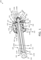
- the electromechanical actuator 100 comprises a reciprocating assembly 102 having a screw 104 comprising a threaded body portion 104A and having a proximal end 104C and a distal end 104B integral with threaded body portion 104A, a nut 106 threadably engaged to the threaded body portion 104A of the screw 104, and a guide 108 mounted on the nut 106.
- the electromechanical actuator 100 comprises a cylinder assembly 110 having an outer hollow cylinder 112 having a proximal end 112A and a distal end 112B and an inner hollow cylinder 114 having a proximal end 114A and a distal end 114B, the inner hollow cylinder 114 enclosed by the outer hollow cylinder 112 and configured to receive the screw 104 of the reciprocating assembly 102 therethrough.
- the distal end of the screw 104B, the distal end 114B of the inner hollow cylinder and the distal end 112B of the outer hollow cylinder are closer to the motor assembly 116 than the proximal end 112A of outer hollow cylinder, the proximal end 114A of the inner hollow cylinder and the proximal end 104 of the screw.
- Each of the proximal end 112A of outer hollow cylinder, the proximal end 114A of the inner hollow cylinder and the proximal end 104C of the screw are directed away from a motor assembly 116 to the same direction.
- the electromechanical actuator 100 comprises a motor assembly 116 concentrically arranged at the distal end 112B of the outer hollow cylinder 112 for partially receiving the cylinder assembly 110.
- the motor assembly 116 having a motor stator 118, a motor rotor 120 surrounded by the motor stator 118, a flange 122 abuts the motor rotor 120 and a pair of motor bearing 124 surrounded by the motor rotor 120.
- the electromechanical actuator 100 comprises a planetary gear assembly 126 operatively arranged in connection with the motor assembly 116 and reciprocating assembly 102.
- the planetary gear assembly 126 comprises a sun gear 128 coupled to the flange of the motor assembly 116 and receiving the distal end 104B of the screw 104 therethrough, a plurality of planet gears 130 operatively coupled to the sun gear 128.
- the planetary gear assembly 126 comprises a ring gear 132 operatively coupled to the plurality of planet gears 130, and a carrier 134 for supporting the plurality of planet gears 130, the carrier 134 operatively coupled to the distal end 104B of the screw 104 for transmitting a rotary motion of the motor assembly 116 to the screw 104 for generating the reciprocating movement to be provided to the inner hollow cylinder 114.
- the carrier 134 of the planetary gear assembly 126 comprises a planer portion 134A configured to support the plurality of planet gears 130, and a hollow protruding portion 134B integral with and extending from the planer portion 134A, the hollow protruding portion 134B configured to receive the distal end 104B of the screw 104 therethrough.
- the electromechanical actuator 100 a bearing assembly 136 having at least one bearing (depicted as first bearing 138 and second bearing 140 arranged on the carrier 134 and a housing 142 abuts the motor stator 118 and configured to surround the planetary gear assembly 126 and the bearing assembly 136.
- the electromechanical actuator 100 comprises a first attachment loop 144 arranged at the proximal end 114A of the inner hollow cylinder 114 and a second attachment loop 146 coupled to the housing 142. Moreover, a bearing rest 150 arranged on the distal end 112B of the outer hollow cylinder 112, the bearing rest 150 supports the pair of motor bearing thereon 138, 140. Furthermore, the electromechanical actuator 100 also includes a first cover plate 152 arranged on the distal end 112B of the outer hollow cylinder 112 and abuts the bearing rest 150, and a second cover plate 154 opposite to the first cover plate 152 and abuts the housing 146.
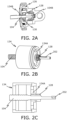
- FIG.s. 2A, 2B and 2C illustrated are an arrangement of a screw 104 with a planetary gear assembly 126 of the electromechanical actuator 100, in accordance with an embodiment of the present disclosure.
- a cross-section of the planetary gear assembly 126 illustrated is a cross-section of the planetary gear assembly 126.
- the sun gear 128 of the planetary gear assembly 126 is coupled to the distal end 104B of the screw 104 therethrough.
- the hollow protruding portion 134B and the distal end 104B of the screw 104 is operatively coupled using a key and hole arrangement 202.
- a carrier 134 of the planetary gear assembly 126 comprises a planer portion 134A configured to support the plurality of planet gears 130 (as shown in FIG. 2A ), and a hollow protruding portion 134B integral with and extending from the planer portion 134A.
- FIG 2C illustrated a cross-section of carrier 134 of the planetary gear assembly 126.
- the hollow protruding portion 134A is configured to receive the distal end 104B of the screw 104 therethrough to connect the screw 104 of the reciprocating assembly 102 with the planetary gear assembly 126. To transfer the rotational motion of the motor assembly 116 into the reciprocation motion of the reciprocating assembly 102.
- a motor assembly 116 of the electromechanical actuator 100 in accordance with an embodiment of the present disclosure.
- a motor assembly 116 having a motor stator 118 and a motor rotor 120 surrounded by the motor stator 118.
- wire terminals 302 extending from the motor stator 118.
- the wire terminals 302 are arranged to connect the motor stator 118 to an external power source.
- the external power source is configured to supply the power from the wire terminals 302 to the motor assembly 116.
- the motor stator 118 comprises a coil housing 304 and a coil arrangement 306 housed within the coil housing 304.
- the motor rotor 120 comprises a magnet housing 308 and a permanent magnet 310 housed within the magnet housing 308.
- the wire terminals 302 extending from the coil arrangement 306 and through the coil housing 304.
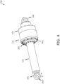
- FIG. 4 illustrated is a perspective view of the electromechanical actuator 100, in accordance with an embodiment of the present disclosure.
- the reciprocating assembly 102, cylinder assembly 110, motor assembly 116, planetary gear assembly 126 and bearing assembly 136 are arranged together using a plurality of bolts 402 to construct the electromechanical actuator 100.
- the first attachment loop 144 and the second attachment loop 146 are arranged on the opposite end of the electromechanical actuator 100.
- the wire terminals 302 extends from the motor stator 118.
- FIG. 5 illustrated is a perspective view of the electromechanical actuator 100, wherein the figure shows the movement of the of inner hollow cylinder and the first attachment loop 144 moving with the cylinder, because it is attached to the cylinder.
- the reciprocating movement of the inner hollow cylinder is achieved by transmitting the rotary motion generated by the motor assembly 116 to the screw 104 (like shown in FIG. 2A-2C ) and further to the inner hollow cylinder.
- the electromechanical actuator 100 is attached from the first attachment loop 144 and the second attachment loop 146 to a desired object/s, which desired object/s can be for example any kind of work machine or any other suitable application in various industries such as for example aerospace, automotive, robotics, manufacturing industry and so forth, for control the movement of various components in machines and systems, by utilizing the reciprocating movement of the actuator.
- desired object/s can be for example any kind of work machine or any other suitable application in various industries such as for example aerospace, automotive, robotics, manufacturing industry and so forth, for control the movement of various components in machines and systems, by utilizing the reciprocating movement of the actuator.
Landscapes
- Engineering & Computer Science (AREA)
- General Engineering & Computer Science (AREA)
- Power Engineering (AREA)
- Mechanical Engineering (AREA)
- Connection Of Motors, Electrical Generators, Mechanical Devices, And The Like (AREA)
Applications Claiming Priority (1)
| Application Number | Priority Date | Filing Date | Title |
|---|---|---|---|
| FI20235384A FI131184B1 (en) | 2023-04-05 | 2023-04-05 | Electromechanical actuator |
Publications (3)
| Publication Number | Publication Date |
|---|---|
| EP4443019A1 true EP4443019A1 (de) | 2024-10-09 |
| EP4443019B1 EP4443019B1 (de) | 2025-12-31 |
| EP4443019C0 EP4443019C0 (de) | 2025-12-31 |
Family
ID=90361776
Family Applications (1)
| Application Number | Title | Priority Date | Filing Date |
|---|---|---|---|
| EP24161433.8A Active EP4443019B1 (de) | 2023-04-05 | 2024-03-05 | Elektromechanischer aktuator |
Country Status (2)
| Country | Link |
|---|---|
| EP (1) | EP4443019B1 (de) |
| FI (1) | FI131184B1 (de) |
Cited By (1)
| Publication number | Priority date | Publication date | Assignee | Title |
|---|---|---|---|---|
| RU2843048C1 (ru) * | 2024-10-01 | 2025-07-07 | Акционерное общество "Федеральный научно-производственный центр "Титан-Баррикады" | Линейный исполнительный электромеханизм |
Citations (3)
| Publication number | Priority date | Publication date | Assignee | Title |
|---|---|---|---|---|
| DE8709223U1 (de) * | 1986-07-14 | 1987-09-17 | Josef Pradler, Konstruktionsbüro, 73230 Kirchheim | Linearantriebseinheit |
| DE10064901A1 (de) * | 2000-03-27 | 2001-10-04 | Continental Teves Ag & Co Ohg | Betätigungseinheit mit einem Gewindetrieb, einem Planetengetriebe und einem von diesen beeinflußten Betätigungselement |
| US20050092558A1 (en) * | 2001-12-13 | 2005-05-05 | Skf Industrie S.P.A. | Screw actuator with a fixed nut |
-
2023
- 2023-04-05 FI FI20235384A patent/FI131184B1/en active
-
2024
- 2024-03-05 EP EP24161433.8A patent/EP4443019B1/de active Active
Patent Citations (3)
| Publication number | Priority date | Publication date | Assignee | Title |
|---|---|---|---|---|
| DE8709223U1 (de) * | 1986-07-14 | 1987-09-17 | Josef Pradler, Konstruktionsbüro, 73230 Kirchheim | Linearantriebseinheit |
| DE10064901A1 (de) * | 2000-03-27 | 2001-10-04 | Continental Teves Ag & Co Ohg | Betätigungseinheit mit einem Gewindetrieb, einem Planetengetriebe und einem von diesen beeinflußten Betätigungselement |
| US20050092558A1 (en) * | 2001-12-13 | 2005-05-05 | Skf Industrie S.P.A. | Screw actuator with a fixed nut |
Cited By (1)
| Publication number | Priority date | Publication date | Assignee | Title |
|---|---|---|---|---|
| RU2843048C1 (ru) * | 2024-10-01 | 2025-07-07 | Акционерное общество "Федеральный научно-производственный центр "Титан-Баррикады" | Линейный исполнительный электромеханизм |
Also Published As
| Publication number | Publication date |
|---|---|
| FI20235384A1 (en) | 2024-10-06 |
| EP4443019B1 (de) | 2025-12-31 |
| EP4443019C0 (de) | 2025-12-31 |
| FI131184B1 (en) | 2024-11-25 |
Similar Documents
| Publication | Publication Date | Title |
|---|---|---|
| US11264865B2 (en) | Actuator | |
| US20120176007A1 (en) | Electric machine device, actuator using the same, motor, robot, and robot hand | |
| CN109591045B (zh) | 一种高集成度高性能机器人关节单元 | |
| US7854592B2 (en) | Wind turbine rotor, a rotation controlling mechanism and a method for controlling at least one blade of a wind turbine rotor | |
| US20080289440A1 (en) | Linear/Rotary Drive Assembly | |
| WO2017138353A1 (ja) | ボールねじ装置およびこれを備える電動アクチュエータ | |
| CN102474157A (zh) | 用于风力涡轮机的电机偏转驱动系统 | |
| EP3429068A1 (de) | Elektrischer stellantrieb | |
| KR102124733B1 (ko) | 토크 증폭 장치 | |
| JP2013099191A (ja) | 電気機械装置およびそれを用いたアクチュエーター、モーター、ロボット、ロボットハンド。 | |
| CN220122721U (zh) | 一种电机 | |
| CN110666836A (zh) | 一种双向输出仿人机器人用臂部一体化关节 | |
| EP4443019B1 (de) | Elektromechanischer aktuator | |
| JP2015074036A (ja) | アクチュエータ及びこのアクチュエータを組み込んだロボットの関節構造 | |
| US9787151B2 (en) | Radial flux alternator | |
| CN110768427A (zh) | 一种内置交流伺服电机直线模组 | |
| CN109849398A (zh) | 一种螺距任意可调的螺旋伺服压力机 | |
| US20250383012A1 (en) | Linear motor | |
| CN113148214A (zh) | 一种航母弹射装置的外转子电机 | |
| CN223854373U (zh) | 一种集成全向风叶的轻量化直驱磁悬浮垂直轴风力发电机 | |
| CN223066935U (zh) | 直线驱动器 | |
| CN118487435B (zh) | 一种带径向自锁的驱电一体化电动缸 | |
| CN222494285U (zh) | 传动丝杠、关节执行器及机器人 | |
| CN102371589A (zh) | 具有断电自锁功能的磁控式机器臂关节制动器 | |
| AU2025210851B1 (en) | Magnetic geared electromechanical system with multi-surface back iron rotor for torque transmission and energy conversion |
Legal Events
| Date | Code | Title | Description |
|---|---|---|---|
| PUAI | Public reference made under article 153(3) epc to a published international application that has entered the european phase |
Free format text: ORIGINAL CODE: 0009012 |
|
| STAA | Information on the status of an ep patent application or granted ep patent |
Free format text: STATUS: THE APPLICATION HAS BEEN PUBLISHED |
|
| STAA | Information on the status of an ep patent application or granted ep patent |
Free format text: STATUS: REQUEST FOR EXAMINATION WAS MADE |
|
| AK | Designated contracting states |
Kind code of ref document: A1 Designated state(s): AL AT BE BG CH CY CZ DE DK EE ES FI FR GB GR HR HU IE IS IT LI LT LU LV MC ME MK MT NL NO PL PT RO RS SE SI SK SM TR |
|
| 17P | Request for examination filed |
Effective date: 20240911 |
|
| RBV | Designated contracting states (corrected) |
Designated state(s): AL AT BE BG CH CY CZ DE DK EE ES FI FR GB GR HR HU IE IS IT LI LT LU LV MC ME MK MT NL NO PL PT RO RS SE SI SK SM TR |
|
| GRAP | Despatch of communication of intention to grant a patent |
Free format text: ORIGINAL CODE: EPIDOSNIGR1 |
|
| STAA | Information on the status of an ep patent application or granted ep patent |
Free format text: STATUS: GRANT OF PATENT IS INTENDED |
|
| INTG | Intention to grant announced |
Effective date: 20250929 |
|
| GRAS | Grant fee paid |
Free format text: ORIGINAL CODE: EPIDOSNIGR3 |
|
| GRAA | (expected) grant |
Free format text: ORIGINAL CODE: 0009210 |
|
| STAA | Information on the status of an ep patent application or granted ep patent |
Free format text: STATUS: THE PATENT HAS BEEN GRANTED |
|
| AK | Designated contracting states |
Kind code of ref document: B1 Designated state(s): AL AT BE BG CH CY CZ DE DK EE ES FI FR GB GR HR HU IE IS IT LI LT LU LV MC ME MK MT NL NO PL PT RO RS SE SI SK SM TR |
|
| REG | Reference to a national code |
Ref country code: CH Ref legal event code: F10 Free format text: ST27 STATUS EVENT CODE: U-0-0-F10-F00 (AS PROVIDED BY THE NATIONAL OFFICE) Effective date: 20251231 Ref country code: GB Ref legal event code: FG4D |
|
| REG | Reference to a national code |
Ref country code: DE Ref legal event code: R096 Ref document number: 602024001862 Country of ref document: DE |
|
| REG | Reference to a national code |
Ref country code: IE Ref legal event code: FG4D |
|
| U01 | Request for unitary effect filed |
Effective date: 20260116 |
|
| U07 | Unitary effect registered |
Designated state(s): AT BE BG DE DK EE FI FR IT LT LU LV MT NL PT RO SE SI Effective date: 20260121 |
|
| PG25 | Lapsed in a contracting state [announced via postgrant information from national office to epo] |
Ref country code: NO Free format text: LAPSE BECAUSE OF FAILURE TO SUBMIT A TRANSLATION OF THE DESCRIPTION OR TO PAY THE FEE WITHIN THE PRESCRIBED TIME-LIMIT Effective date: 20260331 |
|
| PG25 | Lapsed in a contracting state [announced via postgrant information from national office to epo] |
Ref country code: HR Free format text: LAPSE BECAUSE OF FAILURE TO SUBMIT A TRANSLATION OF THE DESCRIPTION OR TO PAY THE FEE WITHIN THE PRESCRIBED TIME-LIMIT Effective date: 20251231 |
|
| PGFP | Annual fee paid to national office [announced via postgrant information from national office to epo] |
Ref country code: AT Payment date: 20260301 Year of fee payment: 3 |
|
| PG25 | Lapsed in a contracting state [announced via postgrant information from national office to epo] |
Ref country code: RS Free format text: LAPSE BECAUSE OF FAILURE TO SUBMIT A TRANSLATION OF THE DESCRIPTION OR TO PAY THE FEE WITHIN THE PRESCRIBED TIME-LIMIT Effective date: 20260331 |