EP4442984A1 - Drosselklappensteuervorrichtung - Google Patents
Drosselklappensteuervorrichtung Download PDFInfo
- Publication number
- EP4442984A1 EP4442984A1 EP24165118.1A EP24165118A EP4442984A1 EP 4442984 A1 EP4442984 A1 EP 4442984A1 EP 24165118 A EP24165118 A EP 24165118A EP 4442984 A1 EP4442984 A1 EP 4442984A1
- Authority
- EP
- European Patent Office
- Prior art keywords
- interlocking member
- rotation
- unit
- operation device
- throttle
- Prior art date
- Legal status (The legal status is an assumption and is not a legal conclusion. Google has not performed a legal analysis and makes no representation as to the accuracy of the status listed.)
- Pending
Links
Images


Classifications
-
- F—MECHANICAL ENGINEERING; LIGHTING; HEATING; WEAPONS; BLASTING
- F02—COMBUSTION ENGINES; HOT-GAS OR COMBUSTION-PRODUCT ENGINE PLANTS
- F02D—CONTROLLING COMBUSTION ENGINES
- F02D11/00—Arrangements for, or adaptations to, non-automatic engine control initiation means, e.g. operator initiated
- F02D11/06—Arrangements for, or adaptations to, non-automatic engine control initiation means, e.g. operator initiated characterised by non-mechanical control linkages, e.g. fluid control linkages or by control linkages with power drive or assistance
- F02D11/10—Arrangements for, or adaptations to, non-automatic engine control initiation means, e.g. operator initiated characterised by non-mechanical control linkages, e.g. fluid control linkages or by control linkages with power drive or assistance of the electric type
- F02D11/106—Detection of demand or actuation
-
- B—PERFORMING OPERATIONS; TRANSPORTING
- B62—LAND VEHICLES FOR TRAVELLING OTHERWISE THAN ON RAILS
- B62K—CYCLES; CYCLE FRAMES; CYCLE STEERING DEVICES; RIDER-OPERATED TERMINAL CONTROLS SPECIALLY ADAPTED FOR CYCLES; CYCLE AXLE SUSPENSIONS; CYCLE SIDECARS, FORECARS, OR THE LIKE
- B62K23/00—Rider-operated controls specially adapted for cycles, i.e. means for initiating control operations, e.g. levers, grips
- B62K23/02—Rider-operated controls specially adapted for cycles, i.e. means for initiating control operations, e.g. levers, grips hand actuated
- B62K23/04—Twist grips
-
- F—MECHANICAL ENGINEERING; LIGHTING; HEATING; WEAPONS; BLASTING
- F02—COMBUSTION ENGINES; HOT-GAS OR COMBUSTION-PRODUCT ENGINE PLANTS
- F02D—CONTROLLING COMBUSTION ENGINES
- F02D11/00—Arrangements for, or adaptations to, non-automatic engine control initiation means, e.g. operator initiated
- F02D11/02—Arrangements for, or adaptations to, non-automatic engine control initiation means, e.g. operator initiated characterised by hand, foot, or like operator controlled initiation means
-
- G—PHYSICS
- G01—MEASURING; TESTING
- G01D—MEASURING NOT SPECIALLY ADAPTED FOR A SPECIFIC VARIABLE; ARRANGEMENTS FOR MEASURING TWO OR MORE VARIABLES NOT COVERED IN A SINGLE OTHER SUBCLASS; TARIFF METERING APPARATUS; MEASURING OR TESTING NOT OTHERWISE PROVIDED FOR
- G01D5/00—Mechanical means for transferring the output of a sensing member; Means for converting the output of a sensing member to another variable where the form or nature of the sensing member does not constrain the means for converting; Transducers not specially adapted for a specific variable
- G01D5/12—Mechanical means for transferring the output of a sensing member; Means for converting the output of a sensing member to another variable where the form or nature of the sensing member does not constrain the means for converting; Transducers not specially adapted for a specific variable using electric or magnetic means
- G01D5/14—Mechanical means for transferring the output of a sensing member; Means for converting the output of a sensing member to another variable where the form or nature of the sensing member does not constrain the means for converting; Transducers not specially adapted for a specific variable using electric or magnetic means influencing the magnitude of a current or voltage
- G01D5/142—Mechanical means for transferring the output of a sensing member; Means for converting the output of a sensing member to another variable where the form or nature of the sensing member does not constrain the means for converting; Transducers not specially adapted for a specific variable using electric or magnetic means influencing the magnitude of a current or voltage using Hall-effect devices
- G01D5/145—Mechanical means for transferring the output of a sensing member; Means for converting the output of a sensing member to another variable where the form or nature of the sensing member does not constrain the means for converting; Transducers not specially adapted for a specific variable using electric or magnetic means influencing the magnitude of a current or voltage using Hall-effect devices influenced by the relative movement between the Hall device and magnetic fields
-
- G—PHYSICS
- G05—CONTROLLING; REGULATING
- G05G—CONTROL DEVICES OR SYSTEMS INSOFAR AS CHARACTERISED BY MECHANICAL FEATURES ONLY
- G05G1/00—Controlling members, e.g. knobs or handles; Assemblies or arrangements thereof; Indicating position of controlling members
- G05G1/08—Controlling members for hand actuation by rotary movement, e.g. hand wheels
-
- G—PHYSICS
- G05—CONTROLLING; REGULATING
- G05G—CONTROL DEVICES OR SYSTEMS INSOFAR AS CHARACTERISED BY MECHANICAL FEATURES ONLY
- G05G23/00—Means for ensuring the correct positioning of parts of control mechanisms, e.g. for taking-up play
Definitions
- the present invention relates to a throttle operation device in which a driving source of a vehicle is controlled based on a rotation operation of an operation unit.
- a throttle operation device configured to detect a rotation angle of a throttle grip by a throttle opening degree sensor such as a potentiometer and transmit a detected value as an electric signal to an electronic control device or the like mounted on the two-wheel vehicle has been widely used.
- the electronic control device performs a predetermined calculation based on the detection signal, and based on the calculation result, a driving source (for example, an ignition timing of an engine, and the opening and closing of an intake valve or a throttle valve) of the vehicle is controlled.
- a throttle operation device in the related art for example, a throttle operation device disclosed in JP2020-122476A is exemplified.
- an arc-shaped magnet is attached to an interlocking member interlocking with a throttle grip, and by detecting magnetic change of the magnet using a magnetic sensor, a rotation angle of the interlocking member and the throttle grip is detected to perform engine control.
- the interlocking member since the arc-shaped magnet is attached to the interlocking member, and the magnetic change of the magnet is detected using the magnetic sensor, the interlocking member may be inclined with respect to a rotation center axis due to backlash or the like between the interlocking member and a case, and may be rotated in that position. In this way, when the interlocking member rotates in an inclined position with respect to the rotation center axis, a position of the magnet with respect to the magnetic sensor is changed, and detection accuracy of a rotation operation angle of the throttle grip (operation unit) by the magnetic sensor (rotation angle detection unit) may be deteriorated.
- An object of the present invention is to provide a throttle operation device that enables to prevent an interlocking member from being inclined with respect to a rotation center axis to maintain detection accuracy of a rotation operation angle of an operation unit.
- the interference portion is provided to hold the posture of the interlocking member by interfering with the facing portion when the interlocking member is inclined with respect to the rotation center axis, so that the interlocking member can be prevented from being inclined with respect to the rotation center axis, and the detection accuracy of the rotation operation angle of the operation unit can be maintained.
- the interference portion includes the rib integrally formed with the interlocking member, so that the interference portion can be easily formed, and the rib can be formed at any position in the interlocking member.
- the interference portion is formed in an arc shape to protrude along a circle centered on the rotation center axis of the interlocking member, so that even when the interference portion interferes with the facing portion when the interlocking member rotates, the rotation of the interlocking member can be maintained smoothly.
- the fixing member fixed to the case while being attached to the interlocking member is provided, and the interference portion is configured to come into contact with the portion of the fixing member, which faces the interference portion, to interfere with the portion, so that the inclination of the interlocking member can be more reliably prevented by the interference portion coming into contact with the fixing member.
- resistance-force applying unit which is attached to the interlocking member and generates friction during rotation of the interlocking member to apply resistance force during rotation operation of the operation unit
- the resistance-force applying unit has a friction material which presses the surface of the fixing member, and the fixing member is attached to the interlocking member to form the unit, so that it is possible to prevent the interlocking member constituting the unit from being inclined with respect to the rotation center axis and to maintain the detection accuracy of the rotation operation angle of the operation unit.
- the interlocking member is provided with the plurality of magnets arranged in an arc shape along the rotation direction of the interlocking member, and the interference portion is formed in an arc shape along the rotation direction of the interlocking member at a position adjacent to the plurality of magnets, so that the relative positions of the plurality of magnets with respect to the rotation angle detection unit disposed in the case can be reliably maintained, and the detection accuracy of the rotation operation angle of the operation unit can be reliably maintained.
- the interference portion has the notch indicating the direction in which the magnet is attached to the interlocking member, so that the work of assembling the magnet to the interlocking member can be performed accurately and smoothly.
- the torsion coil spring is provided to bias the operation unit and the interlocking member toward the initial position during the rotation operation on the operation unit
- the interlocking member has the spring accommodation recessed portion being in an annular shape and configured to accommodate the torsion coil spring, and the plurality of magnet accommodation recessed portions configured to respectively accommodate the plurality of magnets
- the interference portion is formed in an arc shape at a position between the spring accommodation recessed portion and the plurality of magnet accommodation recessed portions, so that the interference portion can be formed by effectively utilizing dead space of the interlocking member.
- a throttle operation device detects a rotation angle of a throttle grip G (operation unit) attached to a handlebar H of a two-wheel vehicle, and transmits a detection signal to an electronic control device such as an ECU mounted on the two-wheel vehicle.
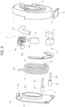
- the throttle operation device includes an interlocking member 1, a magnetic sensor 2 (rotation angle detection unit), a first biasing unit 3, a second biasing unit 4, a resistance-force applying unit 5, a fixing member 6, and a case C.
- the interlocking member 1 is capable of rotating around a rotation center axis P in conjunction with a rotation operation of the throttle grip G of the vehicle.
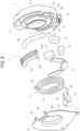
- the interlocking member 1 is made of a substantially cylindrical resin molded product, and includes a fitted portion 1a into which a base end portion of the throttle grip G can be fitted, a plurality of (three in the present embodiment) first accommodation recessed portions 1b that each accommodate a magnet m, a plurality of (two in the present embodiment) second accommodation recessed portions 1d that each accommodate the resistance-force applying unit 5, a third accommodation recessed portion 1c that accommodates the second biasing unit 4, and an annular accommodation recessed portion 1e that accommodates the first biasing unit 3.
- the plurality of first accommodation recessed portions 1b for accommodating the magnets m and the plurality of second accommodation recessed portions 1d for accommodating the resistance-force applying units 5 are formed side by side in an arc shape on one surface, and the third accommodation recessed portion 1c is formed at a position on the same circumference with respect to the first accommodation recessed portions 1b and the second accommodation recessed portions 1d.
- the fitted portion 1a is formed on the other surface of the interlocking member 1.
- the interlocking member 1 is attached by fitting the magnets m into the first accommodation recessed portions 1b, the resistance-force applying units 5 into the second accommodation recessed portions 1d, and the second biasing unit 4 into the third accommodation recessed portion 1c.
- the plurality of magnets m are formed side by side in an arc shape, and the plurality of magnets m, the resistance-force applying units 5, and the second biasing unit 4 are formed on the same circumference.
- each of the plurality of magnets m is formed in a block shape (a cubic shape or a rectangular parallelepiped shape having a rectangular cross section), and by being attached to the first accommodation recessed portions 1b, the plurality of magnets m are formed side by side in an arc shape while being separated from each other by a predetermined distance, and the resistance-force applying units 5 are formed in separated places between the adjacent magnets m, respectively.
- the first accommodation recessed portions 1b formed side by side in an arc shape are covered with a cover member D (see FIGs. 8 and 9 ) to prevent the magnets m fitted into the first accommodation recessed portions 1b from falling off.
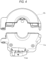
- the case C is fixed to a tip end side (base end side of the throttle grip G) of the handlebar H (see FIGs. 1 and 2 ) of a two-wheel vehicle (vehicle), and is formed by assembling a lower case Ca and an upper case Cb (see FIG. 4 ) with a bolt B (see FIG. 2 ).
- An accommodation recessed portion is formed inside each of the lower case Ca and the upper case Cb, and by assembling the lower case Ca and the upper case Cb in a matching manner, an accommodation space is formed inside.
- the lower case Ca is formed with an accommodation portion Caa that accommodates a substrate K to which the magnetic sensor 2 is attached.
- the magnetic sensor 2 (rotation angle detection unit) includes a sensor disposed in the accommodation portion Caa of the lower case Ca, and detects changes in magnetism generated from the magnets m, so that the rotation angle of the interlocking member 1 can be detected, and the rotation angle of the throttle grip G can be detected.
- a reference sign h in the drawing indicates a wiring extending from the magnetic sensor 2, and a detection signal is transmitted to the vehicle through the wiring h.
- the magnetic sensor 2 can obtain an output voltage corresponding to a change in magnetic field (change in magnetic flux density) of the magnets m caused by the rotation of the interlocking member 1, and includes, for example, a Hall element (specifically, a linear Hall IC capable of obtaining an output voltage proportional to the magnetic field (magnetic flux density) of the magnets m) which is a magnetic sensor using the Hall effect.
- a Hall element specifically, a linear Hall IC capable of obtaining an output voltage proportional to the magnetic field (magnetic flux density) of the magnets m
- magnetism exerted on the magnetic sensor 2 changes.
- three magnets m (a magnet m 1 at a central position and magnets m2 and m3 at both end positions) according to the present embodiment are arranged in a circumferential direction of the interlocking member 1, and poles (N-pole or S-pole) of outside portions a of the magnets (m2 and m3) at both end positions and the pole (N-pole or S-pole) of an outside portion a of the magnet m1 at the central position are set to be different from each other.
- the magnet m1 at the central position may be disposed such that the outside portion a is the N-pole and an inside portion b is the S-pole, and the two adjacent magnets m2 and m3 at both end positions may be disposed such that the outside portion a is the S-pole and an inside portion b is the N-pole.
- the magnet m 1 at the central position may be disposed such that the outside portion a is the S-pole and the inside portion b is the N-pole, and the two adjacent magnets m2 and m3 at both end positions may be disposed such that the outside portion a is the N-pole and the inside portion b is the S-pole.
- the rotation angle of the throttle grip G detected in this way is transmitted as an electric signal to an ECU (engine control unit) mounted on the two-wheel vehicle, and the engine (driving source) of the vehicle can be controlled according to the transmitted rotation angle of the throttle grip G.
- the magnetic sensor 2 can detect a rotation operation in a forward direction ⁇ as well as a rotation operation in a reverse direction ⁇ of the throttle grip G.
- the throttle operation device can control the engine according to the rotation angle of the throttle grip G by a driver performing a rotation operation on the throttle grip G in the forward direction ⁇ from an initial position while holding the throttle grip G, allowing the vehicle to travel at any speed, and can activate or deactivate an electric component (for example, a cancel function of cruise control) mounted on the vehicle by a rotation operation on the throttle grip G in the reverse direction ⁇ from the initial position.
- an electric component for example, a cancel function of cruise control
- the first biasing unit 3 is attached to the annular accommodation recessed portion 1e of the interlocking member 1, and is formed of a torsion coil spring that biases the throttle grip G and the interlocking member 1 toward the initial position at the time of the rotation operation on the throttle grip G in the forward direction ⁇ . As shown in FIGs. 8 and 9 , the first biasing unit 3 includes one end 3a locked to the interlocking member 1, the other end 3b locked to a locking portion 6a of the fixing member 6, and a coil portion 3c located between the one end 3a and the other end 3b.
- the first biasing unit 3 is formed of a torsion coil spring, and has the one end 3a attached to the interlocking member 1 and the other end 3b assembled to the fixing member.
- the second biasing unit 4 biases the throttle grip G and the interlocking member 1 toward the initial position at the time of the rotation operation on the throttle grip G in the reverse direction ⁇ , and is attached to the third accommodation recessed portion 1c of the interlocking member 1, as described above.
- the second biasing unit 4 includes a movable portion 4a formed in an arc shape as a whole and a coil spring 4b accommodated in the movable portion 4a.
- the movable portion 4a is formed of a component having an arc shape extending in the circumferential direction of the interlocking member 1. As shown in FIGs. 8 , 9 , and 14 , the movable portion 4a is integrally formed with an accommodation groove portion 4aa for holding the coil spring 4b, a spring receiving portion 4ac formed of a wall surface of the accommodation groove portion 4aa and configured to receive one end of the coil spring 4b, and a protruding portion 4ab to come into contact with a contact portion 6c of the fixing member 6 (see FIG. 7 ).
- the coil spring 4b is held in the accommodation groove portion 4aa of the movable portion 4a, and is assembled with one end in contact with the spring receiving portion 4ac of the movable portion 4a and the other end in contact with a wall surface 1ca of the third accommodation recessed portion 1c of the interlocking member 1.
- the interlocking member 1 rotates in conjunction with the throttle grip G, while the protruding portion 4ab of the movable portion 4a comes into contact with the contact portion 6c to restrict the rotation, so that the coil spring 4b is compressed.
- the biasing force generated by the compression is applied to the throttle grip G, so that a force is applied to return the throttle grip G and the interlocking member 1 to the initial positions.
- the protruding portion 4ab of the movable portion 4a is separated from the contact portion 6c, so that the coil spring 4b is not compressed and no biasing force is applied.
- the resistance-force applying unit 5 generates friction during rotation of the interlocking member 1 to apply a resistance force during rotation operation on the throttle grip G.
- the resistance-force applying unit 5 includes a friction material 5a formed in a cylindrical shape and a biasing spring 5b that biases the friction material 5a to press the friction material 5a against a surface of the fixing member 6.
- the resistance-force applying unit 5 according to the present embodiment is fitted into and assembled to the second accommodation recessed portion 1d of the interlocking member 1, and is attached to the separated place between the adjacent magnets m.
- the magnets m and the resistance-force applying units 5 are formed on the same circumference in the interlocking member 1.
- the fixing member 6 rotatably holds the interlocking member 1 while positioning the interlocking member 1.
- the fixing member 6 is made of a metal plate-like member formed with a locking portion 6a for locking the other end 3b of the first biasing unit 3, a guide portion 6b for holding the interlocking member 1 while positioning the interlocking member 1, and the contact portion 6c to come into contact with or separated from the protruding portion 4ab of the second biasing unit 4.
- a screw hole through which a screw n (see FIG. 7 ) can be inserted is formed at a predetermined position of the fixing member 6, and the fixing member 6 can be fixed at a predetermined position in the lower case Ca by screwing.
- the locking portion 6a is formed by bending a part of the fixing member 6, and is configured to reliably lock the other end 3b of the first biasing unit 3.
- the guide portion 6b is formed with a portion in which a part of the fixing member 6 is formed in a annular shape to protrude by burring or the like, and is inserted into a center hole of the interlocking member 1 in which the interlocking member 1 is rotatably fitted and positioned (particularly, positioned in a radial direction).
- the contact portion 6c is formed of a portion that comes into contact with the protruding portion 4ab of the second biasing unit 4 and holds the protruding portion 4ab in the circumferential direction.
- the contact portion 6c locks the movable portion 4a of the second biasing unit 4 and restricts rotation in the same direction, so that the interlocking member 1 and the movable portion 4a are moved relative to each other to generate a biasing force of the coil spring 4b.
- the fixing member 6 can hold various components constituting the unit Y, and can generate a resistance force by the resistance-force applying unit 5 when the throttle grip G is subjected to the rotation operation.
- a biasing force is generated by the first biasing unit 3
- a biasing force is generated by the second biasing unit 4.
- the substrate K and the magnetic sensor 2 are arranged in the vicinity of the magnets m arranged in an arc shape. That is, as shown in FIG. 11 , the magnetic sensor 2 and the substrate K are attached to a position close to the central magnet m1 among the three magnets m and at a side position of the interlocking member 1.
- the magnetic sensor 2 approaches the magnet m2 on the right side in the figure.
- the magnetic sensor 2 approaches the magnet m3 on the left side in the figure.
- the plurality of magnets m are formed side by side in an arc shape, and the plurality of magnets m, the resistance-force applying units 5, and the second biasing unit 4 are formed on the same circumference, so that the configuration of the interlocking member 1 can be simplified.
- a general-purpose magnet m (block-shaped magnet) may be used to reduce the manufacturing cost, and the throttle grip G subjected to the rotation operation in the reverse direction ⁇ can be detected over any rotation angle regardless of the size of the magnet.
- the range that can be detected by the magnetic sensor 2 can be freely set.
- the rotation angle that the magnetic sensor 2 can detect when the throttle grip G is subjected to the rotation operation in the forward direction ⁇ and the rotation angle that the magnetic sensor 2 can detect when the throttle grip G is subjected to the rotation operation in the reverse direction ⁇ can be freely set.
- the plurality of first accommodation recessed portions 1b for accommodating the magnets m and the second accommodation recessed portions 1d for accommodating the resistance-force applying units 5 are formed side by side in an arc shape on one surface. Therefore, the plurality of magnets m and the resistance-force applying units 5 can be accurately positioned and easily attached to the interlocking member 1.
- the resistance-force applying unit 5 has the friction material 5a pressed against the surface of the fixing member 6, and the second biasing unit 4 has the coil spring 4b which generates a biasing force by being pressed and compressed by a predetermined portion (the contact portion 6c) of the fixing member 6 when the interlocking member 1 rotates as the throttle grip G rotates in the reverse direction ⁇ . Accordingly, in the present embodiment, the application of the resistance force by the resistance-force applying unit 5 and the biasing by the second biasing unit 4 can be more reliably performed on the fixing member 6.
- the present embodiment includes the case C that rotatably accommodates the interlocking member 1 and has the accommodation portion Caa in which the magnetic sensor 2 is disposed, and the fixing member 6 that is attached to the interlocking member 1 and fixed to the case C.
- the first biasing unit 3 according to the present embodiment is formed of a torsion coil spring, and the one end 3a is locked to the interlocking member 1 and the other end 3b is locked to the fixing member 6. Therefore, in addition to the resistance force applied by the resistance-force applying unit 5 and the biasing by the second biasing unit 4, the biasing by the first biasing unit 3 can be more reliably performed on the fixing member 6.
- the magnets m or the resistance-force applying units 5 are disposed on one side (lower side in FIG. 11 ) of the interlocking member 1 bisected by a plane perpendicular to a line perpendicular to the rotation center axis, and the second biasing unit 4 is disposed on the other side (upper side in FIG. 11 ) of the interlocking member 1 bisected by the plane perpendicular to the line perpendicular to the rotation center axis. Therefore, weight balance of the interlocking member 1 in a rotation direction can be favorably set, and the interlocking member 1 can be rotated stably.
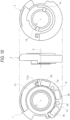
- the throttle operation device is integrally formed with a rib F that serves as an interference portion that holds a posture of the interlocking member 1 by interfering with a facing portion Q (a predetermined portion of the fixing member 6 in the present embodiment) when the interlocking member 1 is inclined with respect to the rotation center axis P.
- the rib F is formed of a portion which is formed in an arc shape to protrude along a circle centered on the rotation center axis P of the interlocking member 1, and as shown in FIG. 6 , the rib F enables to come into contact with the portion Q of the fixing member 6, which faces the rib F (a surface facing the rib F), to interfere with the portion Q.
- the plurality of magnets m are arranged side by side in an arc shape along the rotation direction of the interlocking member 1, and the rib F serving as the interference portion is formed in an arc shape along the rotation direction of the interlocking member 1 at a position adjacent to the plurality of magnets m (a position along the arrangement of the plurality of magnets m).
- the throttle operation device includes the throttle grip G (operation unit) and the first biasing unit 3 (torsion coil spring) that biases the interlocking member 1 toward the initial position.
- the interlocking member 1 is formed with the annular accommodation recessed portion 1e that accommodates the torsion coil spring and the plurality of accommodation recessed portions (first accommodation recessed portions 1b) that respectively accommodate the plurality of magnets m.
- the rib F according to the present embodiment is formed in an arc shape at a position between the annular accommodation recessed portion 1e for the first biasing unit 3 (torsion coil spring) and the plurality of accommodation recessed portions (first accommodation recessed portions 1b) for the magnets m.
- the rib F is provided as the interference portion that holds a posture of the interlocking member 1 by interfering with the facing portion Q when the interlocking member 1 is inclined with respect to the rotation center axis P (that is, a center line of the interlocking member 1 is inclined at a minute angle with respect to the rotation center axis P). Therefore, the interlocking member 1 can be prevented from being inclined with respect to the rotation center axis P, and the detection accuracy of the rotation operation angle of the throttle grip G (operation unit) can be maintained.
- the interference portion is formed of the rib F integrally formed with the interlocking member 1, the interference portion can be easily formed, and the rib F can be formed at any position in the interlocking member 1.
- the rib F serving as the interference portion is formed in an arc shape to protrude along a circle (virtual circle) centered on the rotation center axis P of the interlocking member 1, so that even when the rib F (interference portion) interferes with a portion facing the rib F when the interlocking member 1 rotates, the rotation of the interlocking member 1 can be maintained smoothly.
- the fixing member 6 fixed to the case C while being attached to the interlocking member 1 is provided, and the rib F (interference portion) enables to come into contact with the portion Q of the fixing member 6, which faces the rib F, to interfere with the portion Q, so that the inclination of the interlocking member 1 can be more reliably prevented by the rib F (interference portion) coming into contact with the fixing member 6.
- the present invention includes the resistance-force applying unit 5 that is attached to the interlocking member 1 and generates friction during rotation of the interlocking member 1 to apply a resistance force during the rotation operation of the operation unit (throttle grip G), the resistance-force applying unit 5 has the friction material 5a that presses the surface of the fixing member 6, and the fixing member 6 is attached to the interlocking member 1 to form the unit Y Therefore, it is possible to prevent the interlocking member 1 constituting the unit Y from being inclined with respect to the rotation center axis P and to maintain the detection accuracy of the rotation operation angle of the operation unit (throttle grip G).
- the plurality of magnets m are arranged side by side in an arc shape along the rotation direction of the interlocking member 1, and the rib F serving as the interference portion is formed in an arc shape along the rotation direction of the interlocking member 1 at a position adjacent to the plurality of magnets m. Therefore, the relative positions of the plurality of magnets m with respect to the magnetic sensor 2 (rotation angle detection unit) disposed in the case C can be reliably maintained, and the detection accuracy of the rotation operation angle of the operation unit (throttle grip G) can be reliably maintained.
- the present invention includes the torsion coil spring (first biasing unit 3) that biases the operation unit and the interlocking member 1 toward the initial position at the time of the rotation operation on the operation unit (throttle grip G), the interlocking member 1 is formed with the annular accommodation recessed portion 1e that accommodates the torsion coil spring and the plurality of accommodation recessed portions (first accommodation recessed portions 1b) that respectively accommodate the plurality of magnets m, and the rib F serving as the interference portion is formed in an arc shape at a position between the annular accommodation recessed portion 1e for the torsion coil spring and the plurality of first accommodation recessed portions 1b for the magnets m. Therefore, the rib F can be formed by effectively utilizing the dead space of the interlocking member 1.
- a throttle operation device detects a rotation angle of an operation lever L (operation unit) that can be operated with a finger (thumb) while holding a holding grip M attached to the handlebar H of the two-wheel vehicle, and transmits a detection signal to an electronic control device such as an ECU mounted on the two-wheel vehicle.
- an operation lever L operation unit
- an electronic control device such as an ECU mounted on the two-wheel vehicle.
- the throttle operation device includes the interlocking member 1, the magnetic sensor 2 (rotation angle detection unit), the first biasing unit 3, the second biasing unit 4, the resistance-force applying unit 5, the fixing member 6, the case C, the operation lever L, and the holding grip M.
- the same components as those in the first embodiment are denoted by the same reference numerals, and detailed description thereof is omitted.
- the holding grip M includes a handle grip attached to a tip end portion of the handlebar H of the vehicle, and has a holding region Mb that can be held by a driver, and a flange Ma that protrudes in the circumferential direction and has a diameter larger than the holding region Mb is integrally formed at a base end of the holding grip M.
- the holding grip M according to the present embodiment is intended to be held exclusively by a driver, and is fixed to the tip end portion of the handlebar H by adhesion or the like so as not to rotate (not suitable for rotation operation).
- the operation lever L As shown in FIGs. 15 and 16 , the operation lever L according to the present embodiment is attached to the right side (between the holding grip M and the case C) of the case C rotatably accommodating the interlocking member 1. As shown in FIGs. 17 to 19 , the operation lever L includes a cylindrical rotation portion N1 and an extension portion N2 extending from the rotation portion N1.
- the rotation portion N1 is a portion to be attached to the interlocking member 1, and is formed with a protruding portion Lb protruded to form in an annular shape.
- a fitting portion Lba that can be fitted to the fitted portion 1a of the interlocking member 1 is formed in a part of the protruding portion Lb.
- the extension portion N2 is formed of an arm-shaped portion that protrudes from the rotation portion N1 toward the driver, and an operation portion La is formed at a tip end thereof.
- the operation portion La according to the present embodiment is formed to be bent to the left side (the case C side) with respect to an extending direction of the extension portion N2, and as shown in FIG. 16 , the driver can operate the holding grip M while holding with the thumb of a holding hand.
- the operation portion La can be pushed down to swing in the forward direction ⁇ , and the operation portion La can be pushed up to swing in the reverse direction ⁇ .
- the throttle operation device can control the engine according to the rotation angle of the operation lever L by the driver performing a rotation operation on the operation lever L in the forward direction ⁇ from the initial position, allowing the vehicle to travel at any speed, and can activate or deactivate an electric component (for example, a cancel function of cruise control) mounted on the vehicle by a swing operation on the operation lever L in the reverse direction ⁇ from the initial position.
- an electric component for example, a cancel function of cruise control
- the interlocking member 1 is integrally formed with ribs (F1, F2) that serve as an interference portion that holds a posture of the interlocking member 1 by interfering with the facing portion Q (a predetermined portion of the fixing member 6 in the present embodiment) when the interlocking member 1 is inclined with respect to the rotation center axis P.
- the ribs (F1, F2) include portions which are formed in an arc shape to protrude along a circle centered on the rotation center axis P of the interlocking member 1, and as shown in FIG. 20 , the ribs (F1, F2) enable to come into contact with the portion Q of the fixing member 6, which faces the rib F (a surface facing the rib F), to interfere with the portion Q.
- the rib F1 is formed in an arc shape along the rotation direction of the interlocking member 1 at a position adjacent to the plurality of magnets m (a position along the arrangement of the plurality of magnets m).
- a notch e indicating a direction in which the magnet m is attached to the interlocking member 1 is formed at a predetermined position as shown in FIGs. 21 and 22 .
- the notch e functions as a mark such that the pole of the magnet m is in a preset direction when a worker attaches the magnet m to the first accommodation recessed portion 1b.
- a preset pole is positioned in the outside portion a (see FIG. 22 ). Therefore, according to the present embodiment, by forming the notch e, the work of assembling the magnet m to the interlocking member 1 can be performed accurately and smoothly.
- the rib F 1 is formed in an arc shape at a position between the annular accommodation recessed portion 1e for the first biasing unit 3 (torsion coil spring) and the plurality of accommodation recessed portions (first accommodation recessed portions 1b) for the magnets m.
- the rib F2 has an arc-shaped protruding shape formed at a predetermined distance from the rib F1, and the rib F2 and the rib F1 intermittently form an arc-shaped protruding shape.
- the throttle operation device detects a rotation angle of an operation lever L (operation unit) that can be operated with a finger (thumb) while holding a holding grip M attached to the handlebar H of the two-wheel vehicle, and transmits a detection signal to an electronic control device such as an ECU mounted on the two-wheel vehicle.
- an operation lever L operation unit
- an electronic control device such as an ECU mounted on the two-wheel vehicle.
- the operation lever L according to the present embodiment is attached to the left side (the side opposite to an attachment position of the holding grip M) of the case C rotatably accommodating the interlocking member 1.
- the operation lever L includes the cylindrical rotation portion N1 and the extension portion N2 extending from the rotation portion N1.
- the operation portion La according to the present embodiment is formed to be bent to the right side (the case C side) with respect to the extending direction of the extension portion N2, and as shown in FIG. 24 , the driver can operate the holding grip M while holding with the thumb of a holding hand.
- the operation portion La can be pushed down to swing in the forward direction ⁇ , and the operation portion La can be pushed up to swing in the reverse direction ⁇ .
- the throttle operation device can control the engine according to the rotation angle of the operation lever L by the driver performing a rotation operation on the operation lever L in the forward direction ⁇ from the initial position, allowing the vehicle to travel at any speed, and can activate or deactivate an electric component (for example, a cancel function of cruise control) mounted on the vehicle by a swing operation on the operation lever L in the reverse direction ⁇ from the initial position.
- an electric component for example, a cancel function of cruise control
- the interlocking member 1 is integrally formed with ribs (F1, F2) that serve as an interference portion that holds a posture of the interlocking member 1 by interfering with the facing portion Q (a predetermined portion of the fixing member 6 in the present embodiment) when the interlocking member 1 is inclined with respect to the rotation center axis P.
- the ribs (F1, F2) include portions which are formed in an arc shape to protrude along a circle centered on the rotation center axis P of the interlocking member 1, and as shown in FIG.
- the ribs (F1, F2) enable to come into contact with the portion Q of the fixing member 6, which faces the rib F (a surface facing the rib F), to interfere with the portion Q.
- a notch e similar to that of the second embodiment is formed in the rib F1.
- the present invention is not limited thereto, and may be of other forms.
- the interlocking member 1 may be integrated with the throttle grip G or the operation lever L (including other forms of operation unit), or may not be fixed by the fixing member 6, and the first biasing unit 3 and the second biasing unit 4 may be capable of applying biasing force.
- three magnets m are formed in the interlocking member 1 according to the present embodiment, two or four or more magnets m may be formed.
- One or three or more resistance-force applying units 5 may be formed in the interlocking member 1.
- the ribs (F, F 1, F2) serving as the interference portion are integrally formed with the interlocking member 1 according to the present embodiment.
- the rib may be a portion formed to protrude from the fixing member 6, or the ribs (F, F1, F2) serving as the interference portion or the facing portion Q may be formed on the case C.
- the interference portion is not limited to the ribs (F, F1, F2) formed in an arc shape to protrude along the circle centered on the rotation center axis P of the interlocking member 1, and may be a portion having another shape.
- a vehicle to which the present invention is applied is not limited to a two-wheel vehicle as in the present embodiment, and the present invention may be applied to other vehicles (for example, an ATV, a snowmobile, and the like) having the handlebar H.
- the vehicle to which the present embodiment is applied is not limited to a vehicle in which the driving source is an engine, and may be, for example, a vehicle using an electric motor as the driving source.
- the throttle operation device is in accordance with the spirit of the present invention, it can be applied to devices having a different external shape or having other functions added.
Landscapes
- Engineering & Computer Science (AREA)
- Mechanical Engineering (AREA)
- Chemical & Material Sciences (AREA)
- Combustion & Propulsion (AREA)
- General Engineering & Computer Science (AREA)
- Control Of Throttle Valves Provided In The Intake System Or In The Exhaust System (AREA)
Applications Claiming Priority (2)
| Application Number | Priority Date | Filing Date | Title |
|---|---|---|---|
| JP2023046651 | 2023-03-23 | ||
| JP2023172375A JP2024137621A (ja) | 2023-03-23 | 2023-10-03 | スロットル操作装置 |
Publications (1)
| Publication Number | Publication Date |
|---|---|
| EP4442984A1 true EP4442984A1 (de) | 2024-10-09 |
Family
ID=90571633
Family Applications (1)
| Application Number | Title | Priority Date | Filing Date |
|---|---|---|---|
| EP24165118.1A Pending EP4442984A1 (de) | 2023-03-23 | 2024-03-21 | Drosselklappensteuervorrichtung |
Country Status (1)
| Country | Link |
|---|---|
| EP (1) | EP4442984A1 (de) |
Citations (4)
| Publication number | Priority date | Publication date | Assignee | Title |
|---|---|---|---|---|
| EP1647808B1 (de) * | 2004-10-14 | 2009-01-07 | Yamaha Hatsudoki Kabushiki Kaisha | Regler und im Grätschsitz zu benutzendes Fahrzeug |
| JP5969561B2 (ja) * | 2014-09-09 | 2016-08-17 | 本田技研工業株式会社 | スロットル開度検出装置 |
| JP2020122476A (ja) | 2019-01-29 | 2020-08-13 | 朝日電装株式会社 | スロットルグリップ装置 |
| US10850795B2 (en) * | 2019-01-29 | 2020-12-01 | Asahi Denso Co., Ltd. | Throttle grip device |
-
2024
- 2024-03-21 EP EP24165118.1A patent/EP4442984A1/de active Pending
Patent Citations (4)
| Publication number | Priority date | Publication date | Assignee | Title |
|---|---|---|---|---|
| EP1647808B1 (de) * | 2004-10-14 | 2009-01-07 | Yamaha Hatsudoki Kabushiki Kaisha | Regler und im Grätschsitz zu benutzendes Fahrzeug |
| JP5969561B2 (ja) * | 2014-09-09 | 2016-08-17 | 本田技研工業株式会社 | スロットル開度検出装置 |
| JP2020122476A (ja) | 2019-01-29 | 2020-08-13 | 朝日電装株式会社 | スロットルグリップ装置 |
| US10850795B2 (en) * | 2019-01-29 | 2020-12-01 | Asahi Denso Co., Ltd. | Throttle grip device |
Similar Documents
| Publication | Publication Date | Title |
|---|---|---|
| EP3690217B1 (de) | Drosselgriffvorrichtung | |
| EP3330513B1 (de) | Drosselgriffvorrichtung | |
| US11873056B2 (en) | Throttle grip device | |
| JP7146216B2 (ja) | スロットルグリップ装置 | |
| JP7618140B2 (ja) | スロットル操作装置 | |
| JP6370109B2 (ja) | スロットルグリップ装置 | |
| EP4442984A1 (de) | Drosselklappensteuervorrichtung | |
| JP7032727B2 (ja) | スロットルグリップ装置 | |
| JP6370108B2 (ja) | スロットルグリップ装置 | |
| EP4442983A1 (de) | Drosselklappensteuervorrichtung | |
| JP7553909B2 (ja) | スロットル操作装置 | |
| JP2024137621A (ja) | スロットル操作装置 | |
| JP4706518B2 (ja) | 角度検出器 | |
| JP2024137623A (ja) | スロットル操作装置 | |
| JP7578937B2 (ja) | スロットル操作装置 | |
| JP7272545B2 (ja) | スロットルグリップ装置 | |
| JP2024085860A (ja) | スロットルグリップ装置 | |
| JP7336108B2 (ja) | スロットルグリップ装置 | |
| JP2025062961A (ja) | スロットル操作装置 | |
| JP6993642B2 (ja) | スロットルグリップ装置 | |
| JP7289476B2 (ja) | スロットルグリップ装置及びその教示方法 | |
| JP2020122403A (ja) | スロットルグリップ装置 | |
| JP7241328B2 (ja) | スロットルグリップ装置 | |
| JP2026023112A (ja) | スロットル操作装置 | |
| JP2024085859A (ja) | スロットルグリップ装置 |
Legal Events
| Date | Code | Title | Description |
|---|---|---|---|
| PUAI | Public reference made under article 153(3) epc to a published international application that has entered the european phase |
Free format text: ORIGINAL CODE: 0009012 |
|
| STAA | Information on the status of an ep patent application or granted ep patent |
Free format text: STATUS: THE APPLICATION HAS BEEN PUBLISHED |
|
| AK | Designated contracting states |
Kind code of ref document: A1 Designated state(s): AL AT BE BG CH CY CZ DE DK EE ES FI FR GB GR HR HU IE IS IT LI LT LU LV MC ME MK MT NL NO PL PT RO RS SE SI SK SM TR |
|
| STAA | Information on the status of an ep patent application or granted ep patent |
Free format text: STATUS: REQUEST FOR EXAMINATION WAS MADE |
|
| 17P | Request for examination filed |
Effective date: 20250402 |