EP4442923A1 - A lateral intermediate flashing element for connecting lateral longitudinal flashing elements, a kit comprising such flashing elements, and a method of flashing two roof elements positioned adjacent each other at different altitudes along a slanted roof - Google Patents
A lateral intermediate flashing element for connecting lateral longitudinal flashing elements, a kit comprising such flashing elements, and a method of flashing two roof elements positioned adjacent each other at different altitudes along a slanted roof Download PDFInfo
- Publication number
- EP4442923A1 EP4442923A1 EP24166292.3A EP24166292A EP4442923A1 EP 4442923 A1 EP4442923 A1 EP 4442923A1 EP 24166292 A EP24166292 A EP 24166292A EP 4442923 A1 EP4442923 A1 EP 4442923A1
- Authority
- EP
- European Patent Office
- Prior art keywords
- leg
- flashing
- longitudinal
- lateral
- roof
- Prior art date
- Legal status (The legal status is an assumption and is not a legal conclusion. Google has not performed a legal analysis and makes no representation as to the accuracy of the status listed.)
- Pending
Links
Images




Classifications
-
- E—FIXED CONSTRUCTIONS
- E04—BUILDING
- E04D—ROOF COVERINGS; SKY-LIGHTS; GUTTERS; ROOF-WORKING TOOLS
- E04D13/00—Special arrangements or devices in connection with roof coverings; Protection against birds; Roof drainage ; Sky-lights
- E04D13/14—Junctions of roof sheathings to chimneys or other parts extending above the roof
- E04D13/147—Junctions of roof sheathings to chimneys or other parts extending above the roof specially adapted for inclined roofs
- E04D13/1473—Junctions of roof sheathings to chimneys or other parts extending above the roof specially adapted for inclined roofs specially adapted to the cross-section of the parts extending above the roof
- E04D13/1475—Junctions of roof sheathings to chimneys or other parts extending above the roof specially adapted for inclined roofs specially adapted to the cross-section of the parts extending above the roof wherein the parts extending above the roof have a generally rectangular cross-section
-
- E—FIXED CONSTRUCTIONS
- E04—BUILDING
- E04D—ROOF COVERINGS; SKY-LIGHTS; GUTTERS; ROOF-WORKING TOOLS
- E04D13/00—Special arrangements or devices in connection with roof coverings; Protection against birds; Roof drainage ; Sky-lights
- E04D13/03—Sky-lights; Domes; Ventilating sky-lights
-
- E—FIXED CONSTRUCTIONS
- E04—BUILDING
- E04D—ROOF COVERINGS; SKY-LIGHTS; GUTTERS; ROOF-WORKING TOOLS
- E04D13/00—Special arrangements or devices in connection with roof coverings; Protection against birds; Roof drainage ; Sky-lights
- E04D13/02—Roof-covering aspects of dormer windows
-
- E—FIXED CONSTRUCTIONS
- E04—BUILDING
- E04D—ROOF COVERINGS; SKY-LIGHTS; GUTTERS; ROOF-WORKING TOOLS
- E04D13/00—Special arrangements or devices in connection with roof coverings; Protection against birds; Roof drainage ; Sky-lights
- E04D13/03—Sky-lights; Domes; Ventilating sky-lights
- E04D13/0305—Supports or connecting means for sky-lights of flat or domed shape
- E04D13/031—Supports or connecting means for sky-lights of flat or domed shape characterised by a frame for connection to an inclined roof
-
- E—FIXED CONSTRUCTIONS
- E04—BUILDING
- E04D—ROOF COVERINGS; SKY-LIGHTS; GUTTERS; ROOF-WORKING TOOLS
- E04D13/00—Special arrangements or devices in connection with roof coverings; Protection against birds; Roof drainage ; Sky-lights
- E04D13/14—Junctions of roof sheathings to chimneys or other parts extending above the roof
- E04D13/147—Junctions of roof sheathings to chimneys or other parts extending above the roof specially adapted for inclined roofs
-
- E—FIXED CONSTRUCTIONS
- E06—DOORS, WINDOWS, SHUTTERS, OR ROLLER BLINDS IN GENERAL; LADDERS
- E06B—FIXED OR MOVABLE CLOSURES FOR OPENINGS IN BUILDINGS, VEHICLES, FENCES OR LIKE ENCLOSURES IN GENERAL, e.g. DOORS, WINDOWS, BLINDS, GATES
- E06B7/00—Special arrangements or measures in connection with doors or windows
- E06B7/16—Sealing arrangements on wings or parts co-operating with the wings
- E06B7/18—Sealing arrangements on wings or parts co-operating with the wings by means of movable edgings, e.g. draught sealings additionally used for bolting, e.g. by spring force or with operating lever
Definitions
- the present invention relates to a lateral intermediate flashing element for connecting lateral longitudinal flashing elements for flashing roof elements positioned adjacent each other at different altitudes along a slanted roof, said lateral longitudinal flashing elements having a generally L-shaped cross-section with a first leg and a second leg, the first leg being adapted to be arranged against a side of a respective one of the roof element raising from a plane of the roof in a mounted position, the second leg being arranged to extend along said plane of the roof in the mounted position, the first leg and the second leg being joined at a corner of the L-shape, inner sides of the first leg and the second leg relative to the L-shape constituting a concave side of the lateral longitudinal flashing element, a distal edge portion of the second leg opposite the corner being bent towards the concave side at an angle to form an apex, and said second leg comprising a slit-shaped pocket with an opening towards the distal edge portion and a bottom towards the corner of the L-shap
- the present invention further relates to a kit of flashing elements for flashing roof elements positioned adjacent each other at different altitudes along a slanted roof, comprising such lateral intermediate flashing element, and to a method of flashing two roof elements positioned adjacent each other at different altitudes along a slanted roof using such kit of flashing elements.
- Fig. 1 shows a number of roof elements, more specifically roof windows, mounted in a slanted roof, on one hand adjacent each other in lateral or horizontal side-by-side relationship, and on the other hand adjacent each other at different altitudes along the slanted roof.
- Fig. 1 the wave lines around the windows indicate that the slanted roof is covered with tiles.
- EP 3 480 388 A1 discloses a flashing member for a single roof element, such as a single roof window, and a flashing kit, wherein the flashing member is constituted by a lateral longitudinal flashing element as mentioned above and comprising a slit-shaped pocket with an opening towards a distal edge portion and a bottom towards a corner of an L-shape.
- the slit-shaped pocket provides for accommodating a second longitudinal element of sheet material comprising a first side to be inserted into the pocket.
- the second longitudinal element may e.g. as taught by EP 3 480 388 A1 be provided for covering a gap between the lateral longitudinal flashing element and a neighbouring a carrier profile 200 for supporting a solar collecting panel such as a photo-voltaic panel.
- WO 95/28535 A1 discloses a flashing arrangement for mounting of a (single) roof element in a roof having a thin sheet-formed roofing.
- WO 95/28535 A1 likewise discloses a lateral longitudinal flashing element as mentioned above and comprising a slit-shaped pocket with an opening towards a distal edge portion and a bottom towards a corner of an L-shape, whereby the slit-shaped pocket provides for accommodating a longitudinal edge of thin sheet-formed roofing by said longitudinal edge being inserted into the pocket.
- a lateral intermediate flashing element comprises a longitudinal portion having a generally L-shaped cross-section with a first leg and a second leg, the first leg being adapted to be arranged partly against respective sides of the roof elements, the second leg being arranged to extend along said plane of the roof in the mounted position, the first leg and the second leg being joined at a corner of the L-shape, an inner side of the first leg and an inner side of the second leg relative to the L-shape constituting a concave side of the longitudinal portion, a distal edge portion of the second leg opposite the corner being bent towards the concave side at an angle to form an apex, and said second leg comprising a slit-shaped pocket with an opening towards the distal edge portion and a bottom towards the corner of the L-shape, said pocket being provided by a flat Z-shaped portion of the second leg, said flat Z-shaped portion having a cross-section with a flat Z-shape; and in that the longitudinal portion has an upper longitudinal end and
- the pockets of adjacent lateral longitudinal flashing elements may be combined as extensions of each other by means of the lateral intermediate flashing element, and e.g. a full length of sheet metal roofing may be applied next to roof elements or windows flashed using lateral longitudinal flashing elements the lateral intermediate flashing element.
- the angle of the apex is smaller at the lower longitudinal end than at the upper longitudinal end. This further provides for facilitating use of the lateral intermediate flashing element for combining or connecting lateral intermediate flashing element.
- the lateral intermediate flashing element further comprising a gutter flashing portion attached to the first leg of the longitudinal portion and said first leg comprises a recess corresponding to the gutter flashing portion.
- kit of flashing elements for flashing roof elements positioned adjacent each other at different altitudes along a slanted roof comprising:
- the second leg of the first lateral longitudinal flashing element, and the second lateral longitudinal flashing element respectively has a width between the corner and the apex
- the pocket of the second leg of respectively the lateral intermediate flashing element, the first lateral longitudinal flashing element, and the second lateral longitudinal flashing element has a depth that is equal to or larger than 50% of the width of the lower longitudinal end of the lateral intermediate flashing element; the first lateral longitudinal flashing element; and the second lateral longitudinal flashing element.
- angles forming the apexes are acute angles.
- the opening of the slit-shaped pocket of respectively the lateral intermediate flashing element, the first lateral longitudinal flashing element, and the second lateral longitudinal flashing element is provided at a respective first bend portion, and the bottom of the respective slit-shaped pocket is provided by a respective second bend portion, and in a mounted position,
- a method for flashing two roof elements positioned adjacent each other at different altitudes along a slanted roof comprising:
- Figs. 2 to 7 show a kit of flashing elements 100, 200, 300 for flashing roof elements 400 positioned adjacent each other at different altitudes along a slanted roof 410, comprising a lateral intermediate flashing element, a first lateral longitudinal flashing element 200, and a second lateral longitudinal flashing element 300.
- the lateral intermediate flashing element 100 is for connecting the lateral longitudinal flashing elements 200; 300, and the lateral intermediate flashing element 100 comprises a longitudinal portion 110 having a generally L-shaped cross-section with a first leg 101 and a second leg 102.
- the first leg 101 is adapted to be arranged partly against respective sides of the roof elements 400, and the second leg 102 is arranged to extend along the plane of the roof 410 in the mounted position.
- the first leg 101 and the second leg 102 are joined at a corner 103 of the L-shape, and an inner side 101a of the first leg 101 and an inner side 102a of the second leg 102 relative to the L-shape constitutes a concave side of the longitudinal portion 110.
- a distal edge portion 104 of the second leg 102 opposite the corner 103 is bent towards the concave side at an angle ⁇ 1 to form an apex 114, and the second leg 102 comprises a slit-shaped pocket 105 with an opening towards the distal edge portion and a bottom 106 towards the corner 103 of the L-shape.
- the pocket 106 is provided by a flat Z-shaped portion of the second leg, whereby the flat Z-shaped portion has a cross-section with a flat Z-shape.
- the longitudinal portion 110 has an upper longitudinal end 120 and a lower longitudinal end 121.
- a width W12 of the longitudinal portion 110 between the corner 103 of the L-shape of the longitudinal portion and the apex 114 is smaller at the lower longitudinal end 121 than such width W11 of the longitudinal portion 110 at the upper longitudinal end 120.
- the angle ⁇ 1 of the apex 114 is smaller at the lower longitudinal end 121 than at the upper longitudinal end 120.
- the lateral intermediate flashing element 100 further comprises a gutter flashing portion 130 attached to the first leg of the longitudinal portion and said first leg comprises a recess 131 corresponding to the gutter flashing portion.
- the gutter flashing portion 130 provides in a manner known per se, together with other elements not shown, for flashing horizontally between adjacent roof elements or windows positioned adjacent each other at different altitudes along a slanted roof.
- the first lateral longitudinal flashing elements 200 has a generally L-shaped cross-section with a first leg 201 and a second leg 202.
- the first leg 201 is adapted to be arranged against a side of a respective one of the roof elements 400 raising from a plane of the roof 410 in a mounted position.
- the second leg 202 is arranged to extend along said plane of the roof 410 in the mounted position.
- the first leg 201 and the second leg 202 are joined at a corner 203 of the L-shape, and an inner side 201a of the first leg and an inner side 202a of the second leg relative to the L-shape constitutes a concave side of the lateral longitudinal flashing element 200.
- a distal edge portion 204 of the second leg opposite the corner is bent towards the concave side at an angle ⁇ 2 to form an apex 214 and said second leg 202 comprising a slit-shaped pocket 205 with an opening towards the distal edge portion and a bottom 206 towards the corner 203 of the L-shape.
- the pocket 205 is provided by a flat Z-shaped portion of the second leg, whereby the flat Z-shaped portion has a cross-section with a flat Z-shape.
- the second said lateral longitudinal flashing elements 300 likewise has a generally L-shaped cross-section with a first leg 301 and a second leg 302.
- the first leg 301 is adapted to be arranged against a side of a respective one of the roof elements 400 raising from a plane of the roof 410 in a mounted position
- the second leg 302 is arranged to extend along said plane of the roof 410 in the mounted position.
- the first leg 301 and the second leg 302 are joined at a corner 303 of the L-shape, and an inner side 301a of the first leg and an inner side 302a the second leg relative to the L-shape constitutes a concave side of the lateral longitudinal flashing element 300.
- a distal edge portion 304 of the second leg opposite the corner is bent towards the concave side at an angle ⁇ 3 to form an apex 314, and the second leg 302 comprising a slit-shaped pocket 305 with an opening towards the distal edge portion and a bottom 306 towards the corner 303 of the L-shape.
- the pocket 305 is provided by a flat Z-shaped portion of the second leg, whereby the flat Z-shaped portion has a cross-section with a flat Z-shape.
- the second leg 202, 302 of the the first lateral longitudinal flashing element 200, and the second lateral longitudinal flashing element 300 respectively has a width W between the corner 203, 303 and the apex 214, 314, and the pocket 105, 205, 305 of the second leg 102, 202, 302 of respectively the lateral intermediate flashing element 100, the first lateral longitudinal flashing element 200, and the second lateral longitudinal flashing element 300, has a depth d1; d2; d3 that is equal to or larger than 50% of the width W11; W2; W3 of the lower longitudinal end 121 of the lateral intermediate flashing element 100; the first lateral longitudinal flashing element 200; and the second lateral longitudinal flashing element 300.
- angles ⁇ 1, ⁇ 2, ⁇ 3 forming the apexes 114, 214, 314 are acute angles.
- the opening of the slit-shaped pocket 105, 205, 305 of respectively the lateral intermediate flashing element 100, the first lateral longitudinal flashing element 200, and the second lateral longitudinal flashing element 300 is provided at a respective first bend portion 108, 208, 308, and the bottom 106, 206, 306 of the respective slit-shaped pocket 105, 205, 305 is provided by a respective second bend portion 109 209, 309, and in a mounted position, cf. Figs.
- a longitudinal part of the second bend portion 209 of the first lateral longitudinal flashing element 200 is accommodated in the slit-shaped pocket 105 of the lateral intermediate flashing element 100 at its upper longitudinal end 120, and a longitudinal part of the second bend portion 109 of the lateral intermediate flashing element 100 at its lower longitudinal end 121 is accommodated in the slit-shaped pocket 305 of the second lateral longitudinal flashing element 300.
- the respective sizes or widths of the respective pockets 105, 205, and 305 in a vertical direction as seen in the figures should be sufficient to receive the respective intended bend portions and further the pockets thus joint should have open widths sufficient to receive a sheet-formed element, as explained below.
- second pockets parallel to the first pockets 105, 205, and 305 are opening at the respective second bend portions 109, 209, and 309.
- Some of these second pockets will also accommodate bend portions as it will be envisaged by the skilled person, but e.g. the second pocket of second lateral longitudinal flashing element 300 will not receive a bend portion and may be collapsed as seen in Fig. 7 .
- the longitudinal portion 110 of the lateral intermediate flashing element 100 may be provided as a single bent piece of sheet material or it may be provided e.g. from more bent pieces of sheet material that are connected e.g. by a joint 132.
- the depths d1; d2; d3 of the pockets 105, 205, and 305 opening on the inner sides 102a, 202a, 302a of the second legs 102, 202, 302, respectively are substantially equal.
- the widths W2 and W3 of the first and second lateral longitudinal flashing elements 200 and 300 are substantially equal, whereas the width W12 of the lower longitudinal end 121 of the lateral intermediate flashing element 100 is smaller than the width W3 of the second lateral longitudinal flashing element 300, and width W11 of the upper longitudinal end 120 of the lateral intermediate flashing element 100 is larger than the width W2 of the first lateral longitudinal flashing element 200.
- the lateral intermediate flashing element, the first lateral longitudinal flashing elements 200, and the second lateral longitudinal flashing elements 300 may be assembled by
- Fig. 1 illustrates roof windows mounted at different altitudes along a slanted roof.
- windows are mounted in horizontal side-by-side relation in a lower row 401 and above the lower row 401 an upper row 402 of windows are mounted, thus at a higher altitude along the slanted roof.
- Fig. 1 indicates that the roof is covered with tiles and the present invention is intended for the flashing to cooperate with sheet material, such as metal sheet material
- line VIII-VIII in Fig. 1 indicates the general position of a section to provide a view as shown in Fig. 8 .
- Fig. 8 illustrates how the flashing according to the present invention may cooperate with a second longitudinal element e.g. as taught by EP 3 480 388 A1 from which Fig. 8 is replicated.
- Fig. 8 partially shows part of the window 400 namely a main frame side element 420, a sash element 421, and a pane 422. Further Fig. 8 shows the second lateral longitudinal flashing element 300' in a variant having a slightly deeper pocket 305' than shown in Fig. 7 .
- the shown lateral longitudinal flashing element 300' is mounted with its first leg 301' arranged against an external side of the main frame side element 420.
- the second leg 302' of the lateral longitudinal flashing element 300' is extending along the plane 423 of the roof.
- the main frame side element 420 and the sash element 421 are respectively provided with cladding elements 420a, 421a.
- a carrier profile 424 is provided for carrying e.g. a solar panel (not shown).
- the second longitudinal element 425 is a sheet element with a first side portion 426 accommodated in the pocket 305' of the lateral longitudinal flashing element 300', and with a second side comprising a bent edge portion 427.
- a gasket 428 provides for completing coverage of the roof between the second longitudinal element 425 and the carrier profile 424.
- the present invention provides for a combined slit-shaped pocket 105, 205, 305 to extend all along roof windows, or other roof elements, mounted next to each other at different altitude, as shown in Fig. 1 , whereby the combined slit-shaped pocket may receive e.g. a second longitudinal element like the second longitudinal element 425 extending all along the combined length of the roof windows or roof elements.
- the combined slit-shaped pocket 105, 205, 305 may receive sheet covering for a roof as taught in the above-mentioned WO 95/28535 A1 .
Landscapes
- Engineering & Computer Science (AREA)
- Civil Engineering (AREA)
- Structural Engineering (AREA)
- Architecture (AREA)
- Roof Covering Using Slabs Or Stiff Sheets (AREA)
Abstract
A lateral intermediate flashing element (100) for connecting lateral longitudinal flashing elements (200; 300) for flashing roof elements positioned adjacent each other at different altitudes along a slanted roof, comprises a longitudinal portion (110) with a generally L-shaped cross-section with a first leg (101) and a second leg (102), said second leg (102) comprising a slit-shaped pocket (105) with an opening towards a distal edge portion, the longitudinal portion (110) having an upper longitudinal end (120) and a lower longitudinal end (121), a width of the longitudinal portion (110) of the second leg (102) being smaller at the lower longitudinal end (121) than such width of the longitudinal portion (110) at the upper longitudinal end (120).
Description
- The present invention relates to a lateral intermediate flashing element for connecting lateral longitudinal flashing elements for flashing roof elements positioned adjacent each other at different altitudes along a slanted roof, said lateral longitudinal flashing elements having a generally L-shaped cross-section with a first leg and a second leg, the first leg being adapted to be arranged against a side of a respective one of the roof element raising from a plane of the roof in a mounted position, the second leg being arranged to extend along said plane of the roof in the mounted position, the first leg and the second leg being joined at a corner of the L-shape, inner sides of the first leg and the second leg relative to the L-shape constituting a concave side of the lateral longitudinal flashing element, a distal edge portion of the second leg opposite the corner being bent towards the concave side at an angle to form an apex, and said second leg comprising a slit-shaped pocket with an opening towards the distal edge portion and a bottom towards the corner of the L-shape, said pocket being provided by a flat Z-shaped portion of the second leg, said flat Z-shaped portion having a cross-section with a flat Z-shape.
- The present invention further relates to a kit of flashing elements for flashing roof elements positioned adjacent each other at different altitudes along a slanted roof, comprising such lateral intermediate flashing element, and to a method of flashing two roof elements positioned adjacent each other at different altitudes along a slanted roof using such kit of flashing elements.
-
Fig. 1 shows a number of roof elements, more specifically roof windows, mounted in a slanted roof, on one hand adjacent each other in lateral or horizontal side-by-side relationship, and on the other hand adjacent each other at different altitudes along the slanted roof. - By the expression "at different altitudes along the slanted roof" should be understood that one window is placed further up the roof than a neighbouring window as it is shown in
Fig. 1 and as it is known per se. - In
Fig. 1 , the wave lines around the windows indicate that the slanted roof is covered with tiles. -
EP 3 480 388 A1 discloses a flashing member for a single roof element, such as a single roof window, and a flashing kit, wherein the flashing member is constituted by a lateral longitudinal flashing element as mentioned above and comprising a slit-shaped pocket with an opening towards a distal edge portion and a bottom towards a corner of an L-shape. The slit-shaped pocket provides for accommodating a second longitudinal element of sheet material comprising a first side to be inserted into the pocket. The second longitudinal element may e.g. as taught byEP 3 480 388 A1 be provided for covering a gap between the lateral longitudinal flashing element and a neighbouring acarrier profile 200 for supporting a solar collecting panel such as a photo-voltaic panel. -
WO 95/28535 A1 WO 95/28535 A1 - It is an object of the present invention to provide a lateral intermediate flashing element as mentioned by way of introduction.
- This is obtained in that a lateral intermediate flashing element comprises a longitudinal portion having a generally L-shaped cross-section with a first leg and a second leg, the first leg being adapted to be arranged partly against respective sides of the roof elements, the second leg being arranged to extend along said plane of the roof in the mounted position, the first leg and the second leg being joined at a corner of the L-shape, an inner side of the first leg and an inner side of the second leg relative to the L-shape constituting a concave side of the longitudinal portion, a distal edge portion of the second leg opposite the corner being bent towards the concave side at an angle to form an apex, and said second leg comprising a slit-shaped pocket with an opening towards the distal edge portion and a bottom towards the corner of the L-shape, said pocket being provided by a flat Z-shaped portion of the second leg, said flat Z-shaped portion having a cross-section with a flat Z-shape; and in that the longitudinal portion has an upper longitudinal end and a lower longitudinal end, a width of the longitudinal portion between the corner of the L-shape of the longitudinal portion and the apex being smaller at the lower longitudinal end than such width of the longitudinal portion at the upper longitudinal end. Hereby is obtained that the pockets of adjacent lateral longitudinal flashing elements may be combined as extensions of each other by means of the lateral intermediate flashing element, and e.g. a full length of sheet metal roofing may be applied next to roof elements or windows flashed using lateral longitudinal flashing elements the lateral intermediate flashing element.
- In an embodiment the angle of the apex is smaller at the lower longitudinal end than at the upper longitudinal end. This further provides for facilitating use of the lateral intermediate flashing element for combining or connecting lateral intermediate flashing element.
- In a practical embodiment the lateral intermediate flashing element further comprising a gutter flashing portion attached to the first leg of the longitudinal portion and said first leg comprises a recess corresponding to the gutter flashing portion.
- The object is further obtained by a kit of flashing elements for flashing roof elements positioned adjacent each other at different altitudes along a slanted roof, comprising:
- a lateral intermediate flashing element according to the invention;
- a first lateral longitudinal flashing elements having a generally L-shaped cross-section with a first leg and a second leg, the first leg being adapted to be arranged against a side of a respective one of the roof element raising from a plane of the roof in a mounted position, the second leg being arranged to extend along said plane of the roof in the mounted position, the first leg and the second leg being joined at a corner of the L-shape, an
inner side 101a, 201a, 301a of the first leg and an inner side 102a, 202a, 302a the second leg relative to the L-shape constituting a concave side of the lateral longitudinal flashing element, a distal edge portion of the second leg opposite the corner being bent towards the concave side at an angle to form an apex, and said second leg comprising a slit-shaped pocket with an opening towards the distal edge portion and a bottom towards the corner of the L-shape, said pocket being provided by a flat Z-shaped portion of the second leg, said flat Z-shaped portion having a cross-section with a flat Z-shape; and - a second lateral longitudinal flashing elements having a generally L-shaped cross-section with a first leg and a second leg, the first leg being adapted to be arranged against a side of a respective one of the roof element raising from a plane of the roof in a mounted position, the second leg being arranged to extend along said plane of the roof in the mounted position, the first leg and the second leg being joined at a corner of the L-shape, an inner side of the first leg and an inner side of the second leg relative to the L-shape constituting a concave side of the lateral longitudinal flashing element, a distal edge portion of the second leg opposite the corner being bent towards the concave side at an angle to form an apex, and said second leg comprising a slit-shaped pocket with an opening towards the distal edge portion and a bottom towards the corner of the L-shape, said pocket being provided by a flat Z-shaped portion of the second leg, said flat Z-shaped portion having a cross-section with a flat Z-shape. Hereby is obtained that the pockets of the first and the second lateral longitudinal flashing elements may be combined as extensions of each other by means of the lateral intermediate flashing element and e.g. a full length of sheet metal roofing may be applied next to roof elements or windows flashed using the kit of flashing element.
- In an embodiment wherein the second leg of the the first lateral longitudinal flashing element, and the second lateral longitudinal flashing element, respectively has a width between the corner and the apex, and
the pocket of the second leg of respectively the lateral intermediate flashing element, the first lateral longitudinal flashing element, and the second lateral longitudinal flashing element, has a depth that is equal to or larger than 50% of the width of the lower longitudinal end of the lateral intermediate flashing element; the first lateral longitudinal flashing element; and the second lateral longitudinal flashing element. This provides for adjusting the depth to which e.g. a second longitudinal element is inserted into the combined neighbouring pockets e.g. as taught byEP 3 480 388 A1 . - In a practical embodiment the angles forming the apexes are acute angles.
- In another or further practical embodiment the opening of the slit-shaped pocket of respectively the lateral intermediate flashing element, the first lateral longitudinal flashing element, and the second lateral longitudinal flashing element is provided at a respective first bend portion, and the bottom of the respective slit-shaped pocket is provided by a respective second bend portion, and in a mounted position,
- a longitudinal part of the second bend portion of the first lateral longitudinal flashing element is accommodated in the slit-shaped pocket of the lateral intermediate flashing element at its upper longitudinal end, and
- a longitudinal part of the second bend portion of the lateral intermediate flashing element at its lower longitudinal end is accommodated in the slit-shaped pocket of the second lateral longitudinal flashing element.
- Further, according to the invention a method is provided for flashing two roof elements positioned adjacent each other at different altitudes along a slanted roof, said method comprising:
- providing a kit of flashing elements according to the invention,
- inserting in a longitudinal direction the lower end of the lateral intermediate flashing element into an upper longitudinal end of the second lateral longitudinal flashing element for a longitudinal part of the second bend portion of the lateral intermediate flashing element at its lower longitudinal end to be accommodated in the slit-shaped pocket of the second lateral longitudinal flashing element, and
- inserting in the longitudinal direction a lower longitudinal end of the first lateral longitudinal flashing element into the upper longitudinal end of the lateral intermediate flashing element for a longitudinal part of the second bend portion of the first lateral longitudinal flashing element to be accommodated in the slit-shaped pocket of the lateral intermediate flashing element at its upper longitudinal end.
- In the following the invention will be described in further detail by means of an example of an embodiment having reference to the accompanying schematic drawing, in which
-
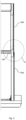
Fig. 1 is a prior art example of roof windows installed in a slanted roof, -
Fig. 2 shows the right-side part of a flashing for two roof elements or windows positioned adjacent each other at different altitudes along a slanted roof, -
Fig. 3 shows in perspective a detail of the flashing shown inFig. 2 generally indicated by circle III, -
Fig. 4 shows an exploded view of the elements ofFig. 3 , -
Fig. 5 shows a top view of the elements shown inFig. 4 , -
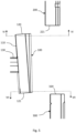
Fig. 6 shows a section as indicated by line VI-VI inFig. 5 , -
Fig. 7 shows a section as indicated by line VII-VII inFig. 5 , and -
Fig. 8 illustrates the use of the flashing elements together with a second longitudinal element inserted into combined neighbouring pockets as taught byEP 3 480 388 A1 . -
Figs. 2 to 7 show a kit offlashing elements roof elements 400 positioned adjacent each other at different altitudes along aslanted roof 410, comprising a lateral intermediate flashing element, a first laterallongitudinal flashing element 200, and a second laterallongitudinal flashing element 300. - The lateral
intermediate flashing element 100 is for connecting the laterallongitudinal flashing elements 200; 300, and the lateralintermediate flashing element 100 comprises
alongitudinal portion 110 having a generally L-shaped cross-section with afirst leg 101 and asecond leg 102. Thefirst leg 101 is adapted to be arranged partly against respective sides of theroof elements 400, and thesecond leg 102 is arranged to extend along the plane of theroof 410 in the mounted position. Thefirst leg 101 and thesecond leg 102 are joined at acorner 103 of the L-shape, and an inner side 101a of thefirst leg 101 and an inner side 102a of thesecond leg 102 relative to the L-shape constitutes a concave side of thelongitudinal portion 110. Adistal edge portion 104 of thesecond leg 102 opposite thecorner 103 is bent towards the concave side at an angle α1 to form anapex 114, and thesecond leg 102 comprises a slit-shaped pocket 105 with an opening towards the distal edge portion and abottom 106 towards thecorner 103 of the L-shape. Thepocket 106 is provided by a flat Z-shaped portion of the second leg, whereby the flat Z-shaped portion has a cross-section with a flat Z-shape. - The
longitudinal portion 110 has an upperlongitudinal end 120 and a lowerlongitudinal end 121. A width W12 of thelongitudinal portion 110 between thecorner 103 of the L-shape of the longitudinal portion and theapex 114 is smaller at the lowerlongitudinal end 121 than such width W11 of thelongitudinal portion 110 at the upperlongitudinal end 120. - In the embodiment shown, cf.
Figs. 6 and 7 , the angle α1 of theapex 114 is smaller at the lowerlongitudinal end 121 than at the upperlongitudinal end 120. - The lateral
intermediate flashing element 100 further comprises agutter flashing portion 130 attached to the first leg of the longitudinal portion and said first leg comprises arecess 131 corresponding to the gutter flashing portion. - The
gutter flashing portion 130 provides in a manner known per se, together with other elements not shown, for flashing horizontally between adjacent roof elements or windows positioned adjacent each other at different altitudes along a slanted roof. - The first lateral
longitudinal flashing elements 200 has a generally L-shaped cross-section with a first leg 201 and a second leg 202. The first leg 201 is adapted to be arranged against a side of a respective one of theroof elements 400 raising from a plane of theroof 410 in a mounted position. The second leg 202 is arranged to extend along said plane of theroof 410 in the mounted position. The first leg 201 and the second leg 202 are joined at acorner 203 of the L-shape, and an inner side 201a of the first leg and an inner side 202a of the second leg relative to the L-shape constitutes a concave side of the laterallongitudinal flashing element 200. Adistal edge portion 204 of the second leg opposite the corner is bent towards the concave side at an angle α2 to form anapex 214 and said second leg 202 comprising a slit-shaped pocket 205 with an opening towards the distal edge portion and abottom 206 towards thecorner 203 of the L-shape. Thepocket 205 is provided by a flat Z-shaped portion of the second leg, whereby the flat Z-shaped portion has a cross-section with a flat Z-shape. - The second said lateral
longitudinal flashing elements 300 likewise has a generally L-shaped cross-section with afirst leg 301 and asecond leg 302. Thefirst leg 301 is adapted to be arranged against a side of a respective one of theroof elements 400 raising from a plane of theroof 410 in a mounted position, and thesecond leg 302 is arranged to extend along said plane of theroof 410 in the mounted position. Thefirst leg 301 and thesecond leg 302 are joined at acorner 303 of the L-shape, and aninner side 301a of the first leg and an inner side 302a the second leg relative to the L-shape constitutes a concave side of the laterallongitudinal flashing element 300. Adistal edge portion 304 of the second leg opposite the corner is bent towards the concave side at an angle α3 to form an apex 314, and thesecond leg 302 comprising a slit-shapedpocket 305 with an opening towards the distal edge portion and a bottom 306 towards thecorner 303 of the L-shape. Thepocket 305 is provided by a flat Z-shaped portion of the second leg, whereby the flat Z-shaped portion has a cross-section with a flat Z-shape. - In the embodiment shown the
second leg 202, 302 of the the first laterallongitudinal flashing element 200, and the second laterallongitudinal flashing element 300, respectively has a width W between thecorner pocket second leg intermediate flashing element 100, the first laterallongitudinal flashing element 200, and the second laterallongitudinal flashing element 300, has a depth d1; d2; d3 that is equal to or larger than 50% of the width W11; W2; W3 of the lowerlongitudinal end 121 of the lateralintermediate flashing element 100; the first laterallongitudinal flashing element 200; and the second laterallongitudinal flashing element 300. - In the embodiment shown the angles α1, α2, α3 forming the
apexes - In the embodiment shown the opening of the slit-shaped
pocket intermediate flashing element 100, the first laterallongitudinal flashing element 200, and the second laterallongitudinal flashing element 300 is provided at a respectivefirst bend portion pocket second bend portion 109 209, 309, and in a mounted position, cf.Figs. 2 and3 , a longitudinal part of thesecond bend portion 209 of the first laterallongitudinal flashing element 200 is accommodated in the slit-shapedpocket 105 of the lateralintermediate flashing element 100 at its upperlongitudinal end 120, and a longitudinal part of thesecond bend portion 109 of the lateralintermediate flashing element 100 at its lowerlongitudinal end 121 is accommodated in the slit-shapedpocket 305 of the second laterallongitudinal flashing element 300. - Referring to
Figs. 6 and 7 , it is noted that the respective sizes or widths of therespective pockets - It is further noted that due to the Z-shape, apart from the
pockets second legs first pockets second bend portions longitudinal flashing element 300 will not receive a bend portion and may be collapsed as seen inFig. 7 . - It should be noted that the e.g. the
longitudinal portion 110 of the lateralintermediate flashing element 100 may be provided as a single bent piece of sheet material or it may be provided e.g. from more bent pieces of sheet material that are connected e.g. by a joint 132. - Referring to the drawing of the second lateral
longitudinal flashing element 300 inFig. 7 it is noted, for the sake of clarity, that the part indicated byreference numeral 310 is a hooked portion at a distal end of the second laterallongitudinal flashing element 300. - In the embodiment shown the depths d1; d2; d3 of the
pockets second legs longitudinal flashing elements longitudinal end 121 of the lateralintermediate flashing element 100 is smaller than the width W3 of the second laterallongitudinal flashing element 300, and width W11 of the upperlongitudinal end 120 of the lateralintermediate flashing element 100 is larger than the width W2 of the first laterallongitudinal flashing element 200. - For flashing a roof element e.g. a roof window, the lateral intermediate flashing element, the first lateral
longitudinal flashing elements 200, and the second laterallongitudinal flashing elements 300 may be assembled by - inserting in a longitudinal direction A the
lower end 121 of the lateralintermediate flashing element 100 into an upperlongitudinal end 320 of the second laterallongitudinal flashing element 300 for a longitudinal part of thesecond bend portion 109 of the lateralintermediate flashing element 100 at its lowerlongitudinal end 121 to be accommodated in the slit-shapedpocket 305 of the second laterallongitudinal flashing element 300, and - inserting in the longitudinal direction A a lower
longitudinal end 221 of the first laterallongitudinal flashing element 200 into the upperlongitudinal end 120 of the lateralintermediate flashing element 100 for a longitudinal part of thesecond bend portion 209 of the first laterallongitudinal flashing element 200 to be accommodated in the slit-shapedpocket 105 of the lateralintermediate flashing element 100 at its upperlongitudinal end 120. -
Fig. 1 illustrates roof windows mounted at different altitudes along a slanted roof. In the example shown, windows are mounted in horizontal side-by-side relation in alower row 401 and above thelower row 401 anupper row 402 of windows are mounted, thus at a higher altitude along the slanted roof. - Whereas
Fig. 1 indicates that the roof is covered with tiles and the present invention is intended for the flashing to cooperate with sheet material, such as metal sheet material, line VIII-VIII inFig. 1 indicates the general position of a section to provide a view as shown inFig. 8 . -
Fig. 8 illustrates how the flashing according to the present invention may cooperate with a second longitudinal element e.g. as taught byEP 3 480 388 A1 from whichFig. 8 is replicated. -
Fig. 8 partially shows part of thewindow 400 namely a mainframe side element 420, asash element 421, and apane 422. FurtherFig. 8 shows the second lateral longitudinal flashing element 300' in a variant having a slightly deeper pocket 305' than shown inFig. 7 . The shown lateral longitudinal flashing element 300' is mounted with its first leg 301' arranged against an external side of the mainframe side element 420. The second leg 302' of the lateral longitudinal flashing element 300' is extending along theplane 423 of the roof. Further, the mainframe side element 420 and thesash element 421 are respectively provided withcladding elements - Next to the window 400 a
carrier profile 424 is provided for carrying e.g. a solar panel (not shown). - In order to provide for covering the roof between the
window 400 and the carrier profile 424 a secondlongitudinal element 425 is provided. The secondlongitudinal element 425 is a sheet element with afirst side portion 426 accommodated in the pocket 305' of the lateral longitudinal flashing element 300', and with a second side comprising abent edge portion 427. Agasket 428 provides for completing coverage of the roof between the secondlongitudinal element 425 and thecarrier profile 424. - The present invention provides for a combined slit-shaped
pocket Fig. 1 , whereby the combined slit-shaped pocket may receive e.g. a second longitudinal element like the secondlongitudinal element 425 extending all along the combined length of the roof windows or roof elements. - As an alternative to a second longitudinal element like the second
longitudinal element 425 the combined slit-shapedpocket WO 95/28535 A1 -
- 100
- lateral intermediate flashing element
- 101
- first leg
- 101a
- inner side (of first leg)
- 102
- second leg
- 102a
- inner side (of second leg)
- 103
- corner
- 104
- distal edge portion
- 114
- apex
- 105
- slit-shaped pocket
- 106
- bottom
- 108
- first bend portion
- 109
- second bend portion
- 110
- longitudinal portion
- 120
- upper longitudinal end
- 121
- lower longitudinal end
- 130
- gutter flashing portion
- 131
- recess
- 132
- joint
- 200
- first lateral longitudinal flashing elements
- 201
- first leg
- 201a
- inner side (of first leg)
- 202
- second leg
- 202a
- inner side (of second leg)
- 203
- corner of the L-shape
- 204
- distal edge portion of the second leg
- 214
- apex
- 205
- slit-shaped pocket
- 206
- bottom
- 208
- first bend portion
- 209
- second bend portion
- 221
- lower longitudinal end
- 300
- second lateral longitudinal flashing elements
- 301
- first leg
- 301a
- inner side (of first leg)
- 302
- second leg
- 302a
- inner side (of second leg)
- 303
- corner of the L-shape
- 304
- distal edge portion of the second leg
- 314
- apex
- 305
- slit-shaped pocket
- 306
- bottom
- 308
- first bend portion
- 309
- second bend portion
- 310
- hooked portion (at distal end)
- 320
- upper longitudinal end
- 400
- roof elements
- 401
- lower row (of roof elements)
- 402
- upper row (of roof elements)
- 410
- slanted roof
- α1, α2, α3
- angle of apex
- A
- longitudinal direction
- W11, W12, W2, W3
- width
- d1, d2, d3
- depth
- 401
- lower row (of windows)
- 402
- upper row (of windows)
- 420
- main frame side element, (external side of the main frame side element 420)
- 420a
- cladding element
- 421
- sash element
- 421a
- cladding element
- 422
- pane
- 423
- plane (of the roof)
- 424
- carrier profile
- 425
- second longitudinal element
- 426
- first side portion (of --- "---)
- 427
- bent edge portion
- 428
- gasket
- 300'
- second lateral longitudinal flashing element
- 301'
- first leg
- 302'
- second leg
- 305'
Claims (8)
- A lateral intermediate flashing element (100) for connecting lateral longitudinal flashing elements (200; 300) for flashing roof elements (400) positioned adjacent each other at different altitudes along a slanted roof (410),said lateral longitudinal flashing elements (200; 300) each having a generally L-shaped cross-section with a first leg (201; 301) and a second leg (202; 302), the first leg (201, 301) being adapted to be arranged against a side of a respective one of the roof element (400) raising from a plane of the roof (410) in a mounted position, the second leg (202; 302) being arranged to extend along said plane of the roof (410) in the mounted position, the first leg (201; 301) and the second leg (202; 302) being joined at a corner (203; 303) of the L-shape, an inner side (201a; 301a) of the first leg and an inner side (202a; 302a) of the second leg relative to the L-shape constituting a concave side of the lateral longitudinal flashing element (200; 300), a distal edge portion (204; 304) of the second leg opposite the corner being bent towards the concave side at an angle (α2; α3) to form an apex (214; 314), and said second leg (202; 302) comprising a slit-shaped pocket (205; 305) with an opening on the inner side towards the distal edge portion and a bottom (206; 306) towards the corner (203; 303) of the L-shape, said pocket (205; 305) being provided by a flat Z-shaped portion of the second leg, said flat Z-shaped portion having a cross-section with a flat Z-shape;characterized in that the lateral intermediate flashing element (100) comprisesa longitudinal portion (110) having a generally L-shaped cross-section with a first leg (101) and a second leg (102), the first leg (101) being adapted to be arranged partly against respective sides of the roof elements (400), the second leg (102) being arranged to extend along said plane of the roof (410) in the mounted position, the first leg (101) and the second leg (102) being joined at a corner (103) of the L-shape, an inner side (101a) of the first leg (101) and an inner side (102a) the second leg (102) relative to the L-shape constituting a concave side of the longitudinal portion (110), a distal edge portion (104) of the second leg (102) opposite the corner (103) being bent towards the concave side at an angle (α1) to form an apex (114), and said second leg (102) comprising a slit-shaped pocket (105) with an opening on the inner side towards the distal edge portion and a bottom (106) towards the corner (103) of the L-shape, said pocket (106) being provided by a flat Z-shaped portion of the second leg, said flat Z-shaped portion having a cross-section with a flat Z-shape;the longitudinal portion (110) having an upper longitudinal end (120) and a lower longitudinal end (121), a width (W11) of the longitudinal portion (110) between the corner (103) of the L-shape of the longitudinal portion and the apex (114) being smaller at the lower longitudinal end (121) than such width (W12) of the longitudinal portion (110) at the upper longitudinal end (120).
- A lateral intermediate flashing element (100) according to claim 1, wherein the angle (α1) of the apex (114) is smaller at the lower longitudinal end (121) than at the upper longitudinal end (120).
- A lateral intermediate flashing element according to claim 1 or 2, further comprising a gutter flashing portion (130) attached to the first leg of the longitudinal portion and said first leg comprises a recess (131) corresponding to the gutter flashing portion.
- A kit of flashing elements (100, 200, 300) for flashing roof elements (400) positioned adjacent each other at different altitudes along a slanted roof (410), comprising:a first lateral longitudinal flashing elements (200) having a generally L-shaped cross-section with a first leg (201) and a second leg (202), the first leg (201) being adapted to be arranged against a side of a respective one of the roof element (400) raising from a plane of the roof (410) in a mounted position, the second leg (202) being arranged to extend along said plane of the roof (410) in the mounted position, the first leg (201) and the second leg (202) being joined at a corner (203) of the L-shape, an inner side (201a) of the first leg and an inner side (202a) the second leg relative to the L-shape constituting a concave side of the lateral longitudinal flashing element (200), a distal edge portion (204) of the second leg opposite the corner being bent towards the concave side at an angle (α2) to form an apex (214), and said second leg (202) comprising a slit-shaped pocket (205) with an opening towards the distal edge portion and a bottom (206) towards the corner (203) of the L-shape, said pocket (205) being provided by a flat Z-shaped portion of the second leg, said flat Z-shaped portion having a cross-section with a flat Z-shape; anda second lateral longitudinal flashing elements (300) having a generally L-shaped cross-section with a first leg (301) and a second leg (302), the first leg (301) being adapted to be arranged against a side of a respective one of the roof element (400) raising from a plane of the roof (410) in a mounted position, the second leg (302) being arranged to extend along said plane of the roof (410) in the mounted position, the first leg (301) and the second leg (302) being joined at a corner (303) of the L-shape, an inner side (301a) of the first leg and an inner side (302a) the second leg relative to the L-shape constituting a concave side of the lateral longitudinal flashing element (300), a distal edge portion (304) of the second leg opposite the corner being bent towards the concave side at an angle (α3) to form an apex (314), and said second leg (302) comprising a slit-shaped pocket (305) with an opening towards the distal edge portion and a bottom (306) towards the corner (303) of the L-shape, said pocket (305) being provided by a flat Z-shaped portion of the second leg, said flat Z-shaped portion having a cross-section with a flat Z-shape,characterized by further comprising a lateral intermediate flashing element according to any one of claims 1 to 3.
- A kit of flashing elements (100, 200, 300) according to claim 4, wherein the second leg (202, 302) of the the first lateral longitudinal flashing element (200), and the second lateral longitudinal flashing element (300), respectively has a width (W2; W3) between the corner (203, 303) and the apex (214, 314), and
the pocket (105, 205, 305) of the second leg (102, 202, 302) of respectively the lateral intermediate flashing element (100), the first lateral longitudinal flashing element (200), and the second lateral longitudinal flashing element (300), has a depth (d1; d2; d3) that is equal to or larger than 50% of the width (W11; W2; W3) of the lower longitudinal end (121) of the lateral intermediate flashing element (100); the first lateral longitudinal flashing element (200); and the second lateral longitudinal flashing element (300). - A kit of flashing elements (100, 200, 300) according to claim 4 or 5, wherein the angles (α1, α2, α3) forming the apexes (114, 214, 314) are acute angles.
- A kit of flashing elements (100, 200, 300) according to any one of claims 4 to 6, wherein the opening of the slit-shaped pocket (105, 205, 305) of respectively the lateral intermediate flashing element (100), the first lateral longitudinal flashing element (200), and the second lateral longitudinal flashing element (300) is provided at a respective first bend portion (108, 208, 308), and the bottom (106, 206, 306) of the respective slit-shaped pocket (105, 205, 305) is provided by a respective second bend portion (109 209, 309), and in a mounted position,a longitudinal part of the second bend portion (209) of the first lateral longitudinal flashing element (200) is accommodated in the slit-shaped pocket (105) of the lateral intermediate flashing element (100) at its upper longitudinal end (120), anda longitudinal part of the second bend portion (109) of the lateral intermediate flashing element (100) at its lower longitudinal end (121) is accommodated in the slit-shaped pocket (305) of the second lateral longitudinal flashing element (300).
- A method of flashing two roof elements (400) positioned adjacent each other at different altitudes along a slanted roof (410), characterized by said method comprising:providing a kit of flashing elements according to claim 7,inserting in a longitudinal direction (A) the lower end (121) of the lateral intermediate flashing element (100) into an upper longitudinal end (320) of the second lateral longitudinal flashing element (300) for a longitudinal part of the second bend portion (109) of the lateral intermediate flashing element (100) at its lower longitudinal end (121) to be accommodated in the slit-shaped pocket (305) of the second lateral longitudinal flashing element (300), andinserting in the longitudinal direction (A) a lower longitudinal end (221) of the first lateral longitudinal flashing element (200) into the upper longitudinal end (120) of the lateral intermediate flashing element (100) for a longitudinal part of the second bend portion (209) of the first lateral longitudinal flashing element (200) to be accommodated in the slit-shaped pocket (105) of the lateral intermediate flashing element (100) at its upper longitudinal end (120).
Applications Claiming Priority (1)
| Application Number | Priority Date | Filing Date | Title |
|---|---|---|---|
| DKPA202370169A DK182073B1 (en) | 2023-04-05 | 2023-04-05 | A lateral intermediate flashing element for connecting lateral longitudinal flashing elements, a kit comprising such flashing elements, and a method of flashing two roof elements positioned adjacent each other at different altitudes along a slanted roof |
Publications (1)
| Publication Number | Publication Date |
|---|---|
| EP4442923A1 true EP4442923A1 (en) | 2024-10-09 |
Family
ID=90482451
Family Applications (1)
| Application Number | Title | Priority Date | Filing Date |
|---|---|---|---|
| EP24166292.3A Pending EP4442923A1 (en) | 2023-04-05 | 2024-03-26 | A lateral intermediate flashing element for connecting lateral longitudinal flashing elements, a kit comprising such flashing elements, and a method of flashing two roof elements positioned adjacent each other at different altitudes along a slanted roof |
Country Status (4)
| Country | Link |
|---|---|
| US (1) | US20240337109A1 (en) |
| EP (1) | EP4442923A1 (en) |
| CN (1) | CN222413773U (en) |
| DK (1) | DK182073B1 (en) |
Citations (6)
| Publication number | Priority date | Publication date | Assignee | Title |
|---|---|---|---|---|
| SE416072B (en) * | 1978-12-19 | 1980-11-24 | Zanda Ab | Plate fitting for connecting a tiled roof to a roof lead- in, wall or the like |
| EP0087647B1 (en) * | 1982-02-26 | 1985-04-24 | V. Kann Rasmussen Holding A/S | Combined covering frame for skylights embedded side by side |
| WO1995028535A1 (en) | 1994-04-18 | 1995-10-26 | V. Kann Rasmussen Industri A/S | A flashing for roof elements |
| EP1581707B1 (en) * | 2002-12-16 | 2009-10-14 | VKR Holding A/S | Side flashing member and a method of making it |
| PL217499B1 (en) * | 2009-11-26 | 2014-07-31 | Fakro Pp Spółka Z Ograniczoną Odpowiedzialnością | Flange sealing the connection of roof penetrating construction with an adjacent outer plating from scale covering |
| EP3480388A1 (en) | 2017-11-03 | 2019-05-08 | VKR Holding A/S | A flashing member for a roof element, such as a roof window, and a flashing kit |
Family Cites Families (5)
| Publication number | Priority date | Publication date | Assignee | Title |
|---|---|---|---|---|
| DK44494A (en) * | 1994-04-18 | 1995-10-19 | Rasmussen Kann Ind As | Covering for roof elements |
| FR2916464B1 (en) * | 2007-05-22 | 2009-09-11 | Terreal Soc Par Actions Simpli | DEVICE FOR INTEGRATING SOLAR PANEL ON A ROOF. |
| PL226250B1 (en) * | 2011-01-31 | 2017-06-30 | Fakro Pp Spółka Z Ograniczoną Odpowiedzialnością | A set of tools for roof work, to seal the joint of an assembly composed of at least two structures that penetrate the roof |
| DK181142B1 (en) * | 2021-10-08 | 2023-02-22 | Vkr Holding As | Packed roof window products |
| US20240328162A1 (en) * | 2023-04-03 | 2024-10-03 | Vkr Holding A/S | Flashing assembly comprising a top flashing arrangement, a roof element system comprising such a flashing assembly, and a method of manufacturing a flashing assembly |
-
2023
- 2023-04-05 DK DKPA202370169A patent/DK182073B1/en active IP Right Grant
-
2024
- 2024-03-26 EP EP24166292.3A patent/EP4442923A1/en active Pending
- 2024-03-29 US US18/621,211 patent/US20240337109A1/en active Pending
- 2024-04-02 CN CN202420671335.5U patent/CN222413773U/en active Active
Patent Citations (6)
| Publication number | Priority date | Publication date | Assignee | Title |
|---|---|---|---|---|
| SE416072B (en) * | 1978-12-19 | 1980-11-24 | Zanda Ab | Plate fitting for connecting a tiled roof to a roof lead- in, wall or the like |
| EP0087647B1 (en) * | 1982-02-26 | 1985-04-24 | V. Kann Rasmussen Holding A/S | Combined covering frame for skylights embedded side by side |
| WO1995028535A1 (en) | 1994-04-18 | 1995-10-26 | V. Kann Rasmussen Industri A/S | A flashing for roof elements |
| EP1581707B1 (en) * | 2002-12-16 | 2009-10-14 | VKR Holding A/S | Side flashing member and a method of making it |
| PL217499B1 (en) * | 2009-11-26 | 2014-07-31 | Fakro Pp Spółka Z Ograniczoną Odpowiedzialnością | Flange sealing the connection of roof penetrating construction with an adjacent outer plating from scale covering |
| EP3480388A1 (en) | 2017-11-03 | 2019-05-08 | VKR Holding A/S | A flashing member for a roof element, such as a roof window, and a flashing kit |
Also Published As
| Publication number | Publication date |
|---|---|
| CN222413773U (en) | 2025-01-28 |
| DK182073B1 (en) | 2025-07-01 |
| DK202370169A1 (en) | 2024-10-24 |
| US20240337109A1 (en) | 2024-10-10 |
Similar Documents
| Publication | Publication Date | Title |
|---|---|---|
| EP2426286A1 (en) | Solar cell module fixing structure and frame and fixing member for solar cell module | |
| CA2327347C (en) | Flashing member and frame for a roof-penetrating building part | |
| EP1581707B1 (en) | Side flashing member and a method of making it | |
| SK157894A3 (en) | Sealing mechanism for windows,in particular roof windows | |
| BR112017024980B1 (en) | panel and roof | |
| EP4442924A1 (en) | A flashing assembly for use between two roof windows mounted in an inclined roof structure, a group of roof windows mounted using such a flashing assembly, and a method for mounting a flashing assembly between two roof windows | |
| EP3480388B1 (en) | A flashing member for a roof element, such as a roof window, and a flashing kit | |
| CN100473793C (en) | Side flashing member and method of manufacturing the same | |
| EP3404162A1 (en) | A roof window installed in an inclined roof structure with a flashing assembly and a method for weather proofing a roof window | |
| US20240328162A1 (en) | Flashing assembly comprising a top flashing arrangement, a roof element system comprising such a flashing assembly, and a method of manufacturing a flashing assembly | |
| DE69513162T2 (en) | CONNECTING STRIP FOR ROOF ELEMENTS | |
| EP1173645B1 (en) | A mounting and hinge fitting for a panel and a panel system comprising such fittings | |
| US20240337109A1 (en) | lateral intermediate flashing element for connecting lateral longitudinal flashing elements, a kit comprising such flashing elements, and a method of flashing two roof elements positioned adjacent each other at different altitudes along a slanted roof | |
| EP4150757B1 (en) | System and method for connecting and fixing framed solar panels to make a wheatherproof building-integrated modular surface | |
| US20260098407A1 (en) | Flashing assembly for use between two roof windows mounted in an inclined roof structure, a group of roof windows mounted with such a flashing assembly, and a method for mounting a flashing assembly between two roof windows | |
| PL247467B1 (en) | A sheet metal flashing element made of sheet metal | |
| EP4442925A1 (en) | A flashing assembly comprising a top flashing arrangement, a roof element system comprising such a flashing assembly, and a method of manufacturing a flashing assembly | |
| WO2010128081A2 (en) | Facade element utilizing solar energy, facade comprising said facade element, and method for the production of a facade | |
| WO2022055380A1 (en) | Modular roofing panel and method of installing roof covering | |
| JP3099587U (en) | Roofing material | |
| EP4722465A2 (en) | A kit of covering members, a method of manufacturing a kit of covering members, and use of the kit of covering members | |
| JP2008050886A (en) | Roof ridge structure | |
| JPH0328647Y2 (en) | ||
| PL642S2 (en) | Window blind set | |
| JP2002061336A (en) | Solar cell module and method of laying the same |
Legal Events
| Date | Code | Title | Description |
|---|---|---|---|
| PUAI | Public reference made under article 153(3) epc to a published international application that has entered the european phase |
Free format text: ORIGINAL CODE: 0009012 |
|
| STAA | Information on the status of an ep patent application or granted ep patent |
Free format text: STATUS: THE APPLICATION HAS BEEN PUBLISHED |
|
| AK | Designated contracting states |
Kind code of ref document: A1 Designated state(s): AL AT BE BG CH CY CZ DE DK EE ES FI FR GB GR HR HU IE IS IT LI LT LU LV MC ME MK MT NL NO PL PT RO RS SE SI SK SM TR |
|
| STAA | Information on the status of an ep patent application or granted ep patent |
Free format text: STATUS: REQUEST FOR EXAMINATION WAS MADE |
|
| 17P | Request for examination filed |
Effective date: 20250407 |