EP4440797B1 - Roboterarm mit einem zusatzabtriebsglied - Google Patents
Roboterarm mit einem zusatzabtriebsglied Download PDFInfo
- Publication number
- EP4440797B1 EP4440797B1 EP22814072.9A EP22814072A EP4440797B1 EP 4440797 B1 EP4440797 B1 EP 4440797B1 EP 22814072 A EP22814072 A EP 22814072A EP 4440797 B1 EP4440797 B1 EP 4440797B1
- Authority
- EP
- European Patent Office
- Prior art keywords
- link
- additional output
- robot arm
- hand
- distal end
- Prior art date
- Legal status (The legal status is an assumption and is not a legal conclusion. Google has not performed a legal analysis and makes no representation as to the accuracy of the status listed.)
- Active
Links
Images


Classifications
-
- G—PHYSICS
- G05—CONTROLLING; REGULATING
- G05B—CONTROL OR REGULATING SYSTEMS IN GENERAL; FUNCTIONAL ELEMENTS OF SUCH SYSTEMS; MONITORING OR TESTING ARRANGEMENTS FOR SUCH SYSTEMS OR ELEMENTS
- G05B19/00—Programme-control systems
- G05B19/02—Programme-control systems electric
- G05B19/42—Recording and playback systems, i.e. in which the programme is recorded from a cycle of operations, e.g. the cycle of operations being manually controlled, after which this record is played back on the same machine
- G05B19/423—Teaching successive positions by walk-through, i.e. the tool head or end effector being grasped and guided directly, with or without servo-assistance, to follow a path
-
- B—PERFORMING OPERATIONS; TRANSPORTING
- B25—HAND TOOLS; PORTABLE POWER-DRIVEN TOOLS; MANIPULATORS
- B25J—MANIPULATORS; CHAMBERS PROVIDED WITH MANIPULATION DEVICES
- B25J9/00—Programme-controlled manipulators
- B25J9/10—Programme-controlled manipulators characterised by positioning means for manipulator elements
- B25J9/106—Programme-controlled manipulators characterised by positioning means for manipulator elements with articulated links
-
- B—PERFORMING OPERATIONS; TRANSPORTING
- B25—HAND TOOLS; PORTABLE POWER-DRIVEN TOOLS; MANIPULATORS
- B25J—MANIPULATORS; CHAMBERS PROVIDED WITH MANIPULATION DEVICES
- B25J9/00—Programme-controlled manipulators
- B25J9/08—Programme-controlled manipulators characterised by modular constructions
-
- B—PERFORMING OPERATIONS; TRANSPORTING
- B25—HAND TOOLS; PORTABLE POWER-DRIVEN TOOLS; MANIPULATORS
- B25J—MANIPULATORS; CHAMBERS PROVIDED WITH MANIPULATION DEVICES
- B25J9/00—Programme-controlled manipulators
- B25J9/16—Programme controls
- B25J9/1656—Programme controls characterised by programming, planning systems for manipulators
-
- G—PHYSICS
- G05—CONTROLLING; REGULATING
- G05B—CONTROL OR REGULATING SYSTEMS IN GENERAL; FUNCTIONAL ELEMENTS OF SUCH SYSTEMS; MONITORING OR TESTING ARRANGEMENTS FOR SUCH SYSTEMS OR ELEMENTS
- G05B2219/00—Program-control systems
- G05B2219/30—Nc systems
- G05B2219/39—Robotics, robotics to robotics hand
- G05B2219/39427—Panel on arm, hand of robot, controlled axis
-
- G—PHYSICS
- G05—CONTROLLING; REGULATING
- G05B—CONTROL OR REGULATING SYSTEMS IN GENERAL; FUNCTIONAL ELEMENTS OF SUCH SYSTEMS; MONITORING OR TESTING ARRANGEMENTS FOR SUCH SYSTEMS OR ELEMENTS
- G05B2219/00—Program-control systems
- G05B2219/30—Nc systems
- G05B2219/39—Robotics, robotics to robotics hand
- G05B2219/39439—Joystick, handle, lever controls manipulator directly, manually by operator
Definitions
- the invention relates to a robot arm with a plurality of joints and a plurality of links which are adjustable relative to one another by the movements of the joints of the robot arm, wherein each driven joint is assigned a drive device and the respective drive device is designed to adjust the joint of the robot arm assigned to it, specifically by automatically controlling a motor of the respective drive device, comprising a distal end link designed as a tool flange, a hand link immediately upstream of the distal end link in the kinematic chain of joints and links, on which hand link the distal end link is mounted so as to be rotatable about a flange axis of rotation.
- the WO 2015/078585 A2 describes a robot arm with at least two arm modules movable relative to one another and at least one manually operable input module for generating control signals for controlling the robot arm on the basis of a user input, in which both arm modules have a first interface to which the input module can be selectively mounted.
- the EP 1 671 755 A1 describes a horizontally steered robot with an upper and lower end effector attachment. This robot is designed to handle various work shapes and workpieces by selectively utilizing the upper and lower sides of a work spindle.
- the object of the invention is to create a robot arm which has an extended useful range.
- a robot arm with a plurality of joints and a plurality of links which are adjustable relative to one another by the movements of the joints of the robot arm, wherein each driven joint is assigned a drive device and the respective drive device is designed to adjust the joint of the robot arm assigned to it, specifically by automatically controlling a motor of the respective drive device, having a distal end link designed as a tool flange, a handle directly upstream of the distal end link in the kinematic chain of joints and links, on which handle the distal end link is mounted so as to be rotatable about a flange axis of rotation, and an additional output link mounted on the handle so as to be rotatable about an axis of rotation parallel to the flange axis of rotation, which additional output link is arranged on the handle opposite the distal end link, wherein the distal end link is assigned a first drive device which is designed to move the distal end link and the additional output link (10) is assigned a second drive device which is different from the first drive device and is
- One or more of the joints can be designed as rotary joints.
- Each link of the robot arm connects two adjacent joints of the robot arm with a fixed relative assignment of the positions and orientations of the adjacent joints to one another.
- Each link of the robot arm can be designed as a single-part or multi-part joint.
- the drive devices can be automated by a robot controller, in particular optionally according to a robot program or in a manual operation of the robot manually actuated via an input device, drive-controlled or alternatively also in a force/torque-controlled operation of the robot arm by manually guiding the robot arm by grasping and moving at least one of its links.
- the respective drive device can be formed by a controllable motor.
- the respective drive device can in particular comprise an electric motor.
- the drive device can additionally comprise a gear and/or a drive control device.
- the drive device can be designed for controlled operation of the motor.
- the drive device in particular the drive control device comprises a control device, in particular an electrical control device.
- the tool flange forms a coupling means to which robot tools, which are held, moved, guided, and optionally also controlled by the robot arm, can be attached to the robot arm.
- the robot tool can, for example, be a gripper designed to grasp an object that is to be handled by moving the robot arm.
- the robot tool can also be a processing tool, such as a welding gun or another tool, in particular for mechanically processing or handling a workpiece.
- the tool flange can, in particular, be a flange with a flange pattern according to ISO 9409-1:2004-03.
- the tool flange can also be referred to as the mechanical interface of the robot arm.
- the distal end link is the link of the robot arm which, in the kinematic chain of the multiple links and joints of the robot arm, is furthest away from its base, the basic frame.
- the base i.e. the basic frame of the robot arm
- the kinematic chain of the multiple links and joints of the robot arm is usually lined up or counted starting from the base, i.e. starting from the basic frame, in the direction of the distal end link, i.e. the hand flange of the robot arm.
- all links following the base or basic frame are downstream of the base or basic frame. All links of the robot arm which are different from the distal end link, i.e.
- the hand flange of the robot arm are upstream of the distal end link or hand flange of the robot arm.
- the penultimate link of the robot arm in the kinematic chain is positioned directly in front of the distal end link or the hand flange of the robot arm and forms the hand link.
- the link immediately in front of the distal end link (seventh link) or the hand flange of the robot arm is referred to as the sixth link.
- the base or basic frame of the robot arm therefore forms the first link of the robot arm.
- the penultimate link of the robot arm in the kinematic chain is adjusted directly by the fifth joint and forms the hand link.
- the link immediately in front of the distal end link (eighth link) or the hand flange of the robot arm is referred to as the seventh link.
- the base or base frame of the robot arm forms the first link of the robot arm.
- the second-to-last link in the kinematic chain is thus directly adjusted by the sixth joint and forms the hand link.
- the distal end member which forms the tool flange, is mounted on the handle so that it can rotate about its flange rotation axis by means of a swivel joint.
- the handle has an additional output member which is mounted so as to be rotatable about an axis of rotation parallel to the flange axis of rotation and which is arranged on the handle opposite the distal end member.
- the additional output link is a different output link from the tool flange, which is rotatably mounted on the handle is rotatable about a rotation axis parallel to the flange rotation axis, and is also actively adjustable, i.e., actively rotatable. Active rotation of the additional output member can be achieved by a separate drive or motor specifically assigned to the additional output member, or by one of the drive devices of the joints of the robot arm, in particular by the drive device that drives the tool flange and/or directly drives the hand member.
- the robot arm can have a mechanical configuration such that the flange rotation axis of the tool flange always runs parallel to the rotation axis of the additional output member and/or a hand-guide means, in particular the flange rotation axis of the tool flange and the rotation axis of the additional output member or the hand-guide means always lie on the same straight line, and a pivot axis, about which the hand member is rotatably mounted on an arm member of the robot arm immediately upstream of the hand member in the kinematic chain, is always oriented perpendicular to the flange rotation axis of the tool flange and to the rotation axis of the additional output member or the hand-guide means.
- a torque can be transmitted to a functional element coupled to the additional output element via the drivable additional output element.
- a torque can also be transmitted to the additional output element via the functional element.
- the functional element can be a manual interface.
- the manual interface can be a hand-guiding means, in particular a hand rest and/or a handle.
- a user of the robot arm can grasp or grip the hand guide, the hand rest and/or the handle and, for example, in force/torque-controlled operation of the robot arm, adjust the robot arm by manually guiding the robot arm while grasping the hand rest and/or the handle and consequently by moving at least one of the links of the robot arm. Due to the drivability of the additional output link to which the functional element is coupled, the hand guide, the hand rest or the handle can also be actively driven in order to provide tactile feedback to the user who grasps or grips the hand guide, the hand rest or the handle.
- the hand-guiding device enables intuitive manual guidance of all degrees of freedom of the robot arm on a generously dimensioned hand-supporting surface. However, unlike the state of the art, this neither reduces the payload due to a larger effective flange distance nor adversely affects the distal interference contour.
- This user interface enables both direct manual guidance of the robot arm (in one hand-guiding mode) and (in another mode) as an input element for entering commands and settings on the robot or robot controller (input mode).
- the functional element can be a manual input device.
- the functional element can have one or more input devices.
- Each input device can be designed as a single individual input element for controlling a single function.
- the input device can be designed as a multi-input element for controlling several individual functions or can have several individual input elements. wherein each of the plurality of individual input elements can be designed to control an individual function.
- the functional element can be a combination of a manual interface, a hand-guiding means, a hand rest and/or a handle, and at least one manual input means. Due to the drivability of the additional output member to which the functional element is coupled, the manual input means can also be actively driven in order to provide the user who is currently operating the manual input means with tactile feedback during manual input.
- the functional element can be an additional tool.
- the additional output member forms an additional coupling means to which additional robot tools, which can be held, moved, guided, and optionally also controlled by the robot arm, can be attached to the robot arm.
- the additional robot tool can, for example, be an additional gripper designed to grasp an object to be handled by moving the robot arm.
- the robot tool can also be an additional processing tool, such as welding tongs or another tool, in particular for mechanically processing or handling a workpiece.
- the additional output member can have an additional tool flange, which can in particular be an additional flange with a flange pattern according to ISO 9409-1:2004-03.
- the additional tool flange can also be referred to as an additional mechanical interface of the robot arm.
- the further training courses described below can be applied either within the first design, the second design and/or the third design.
- a gear mechanism may be arranged within the hand member, which gear mechanism is designed to couple the additional output member to the distal end member in order to convert a movement of the distal end member into a movement of the additional output member and/or to convert a movement of the additional output member into a movement of the distal end member.
- the transmission can be a simple mechanical coupling that directly converts the movement of the distal end link into a uniform movement of the additional output link.
- the transmission can, for example, be a simple shaft into which torque is introduced by the distal end link, transmitted through the shaft, and output to the additional output link.
- the transmission can comprise a shaft which is designed to transmit a torque between the additional output member and the distal end member.
- the shaft can be fixed at one end to the distal end member and at its opposite end to the additional output member. In this way, a rotary movement of the distal end member can be directly converted into a uniform movement of the additional output member. In the same way, a rotary movement of the additional output member can also be directly converted into a uniform movement of the distal end member if a manual interface, or a hand rest and/or a handle, is connected to the additional output member, which can be manually rotated by the hand of a user. can be used to manually adjust the distal end segment.
- the transmission can also have at least one gear ratio, which can create a gear ratio such that, despite the mechanical coupling of the distal end member and the additional output member, the additional output member has a different speed during rotation than the respective speed of the distal end member.
- the gear ratio can be greater than 1.
- the gear ratio can be less than 1.
- the transmission may comprise a switchable clutch configured to transmit torque between the auxiliary output member and the distal end member in an engaged state and to interrupt transmission of torque between the auxiliary output member and the distal end member in a disengaged state.
- the switchable clutch can be manually switchable.
- an actuating device can be arranged on the handle, which can be manually operated, for example, by a user's hand, to switch the clutch.
- the actuating device can be designed to switch the clutch mechanically.
- the actuating device can be designed to switch the clutch driven by a drive device, specifically controlled by the manually operated actuating device.
- the switchable clutch can be switched automatically by a robot controller controlling the robot arm.
- a first drive device can be assigned to the distal end member, which is designed to move the distal end member, and a second drive device different from the first drive device can be assigned to the additional output member, which second drive device is designed to move the additional output member.
- the second drive device associated with the additional output member can be controlled independently of the first drive device associated with the distal end member. Such control of the first drive device and the second drive device can be performed by the robot controller.
- the second drive device associated with the additional output member can be controlled as a function of the first drive device associated with the distal end member.
- control of the first drive device and the second drive device can be performed by the robot controller.
- the robot controller can be designed and configured to control both the first drive device and the second drive device such that the distal end member and the additional output member execute synchronous movements.
- the robot controller can, in particular, be designed and configured to simulate a virtual transmission ratio by controlling the distal end member and/or the additional output member, in which the additional output member has a different speed during rotational movement than the respective speed of the distal end member.
- the virtual transmission ratio can be greater than 1. Alternatively, the virtual transmission ratio can be less than 1.
- the first drive device may comprise a first motor and the second drive device may comprise a second motor, wherein the first motor and the second motor can be controlled in dependence on one another by a control device, for example the robot control of the robot arm.
- At least one first position sensor can be assigned to the distal end member, which is designed to detect the rotational position of the distal end member, and at least one second position sensor can be assigned to the additional output member, which is designed to detect the rotational position of the additional output member.
- the first position sensor and the second position sensor can be connected for control purposes to the control device or to the robot control of the robot arm, so that the robot control can control the first drive device and/or the second drive device in accordance with the desired behavior of the distal end member and/or the additional output member depending on the detected sensor values of the first position sensor and the second position sensor.
- a hand guide means arranged on the hand member can be connected to the additional output member in such a way that the additional output member can be adjusted by manually actuating the hand guide means and/or the hand guide means can be automatically adjusted by automatically driving the additional output member.
- this can have a rotary actuator rotatably mounted on the handle, which has a ring with a circumferential ring surface and a has an end face delimited by a circumferential ring surface.
- the end face can be at least largely or completely flat.
- the end face of the rotary actuator can extend at least substantially and exactly parallel to the flange plane of the tool flange.
- the surface of the end face of the rotary actuator points in a direction opposite to the surface of the tool flange.
- a rotatable mounting of the rotary actuator on the handle can either be achieved by the rotary actuator being rotatably mounted on a housing component of the handle.
- a rotatable mounting of the rotary actuator on the handle can be achieved by the rotary actuator being fastened to the additional output member, whereby the additional output member is accordingly rotatably mounted within the handle.
- the rotary actuator can be coupled to the additional output member in a manually detachable and re-attachable manner.
- the rotary actuator can have a locking device which specifies a locking position for evenly spaced angular positions of the rotary actuator, which can only be left when the rotary actuator is turned if a predetermined minimum triggering force is overcome in order to be able to skip an adjacent locking position.
- the hand guide means can be manually detachably attached to the handle or the additional output member and the additional output member can have a tool coupling means to which an additional tool can be coupled, wherein in a fastened state of the hand guide means on the handle or the additional output member the tool coupling means is covered by the hand guide means and in a removed state of the hand guide means from the handle or the tool coupling means for coupling a tool is accessible to the additional output member.
- a manual guide means or an additional tool can be coupled to the additional output member.
- the manual guide means attached to the additional output member can additionally form a securing means that prevents unwanted manual intervention in the additional output member, particularly when the additional output member is in motion.
- the manual guide means does not necessarily have to be coupled to the additional output member, but can instead simply be attached to a housing section of the handle.
- the manual guide means then also functions as a cover cap.
- the hand-guiding means may comprise a gripping portion or a handle with at least one gripping portion configured for manually guiding the robot arm by a user's hand.
- the hand-guiding means may accordingly comprise a projecting gripping member that can be grasped by a user's hand in order to move the hand member of the robot arm by moving the gripping member grasped by the hand, and thus to be able to change the joint angle positions of the robot arm.
- the hand-guiding means may also have a grip portion which does not protrude but is essentially formed on a surface of the hand-guiding means.
- this can be formed by a structured surface of an annular surface of the hand guide means.
- the structured surface can be formed by several discrete elevations on the annular surface of the hand-guiding means.
- the several discrete elevations can be evenly distributed around the circumference of the annular surface.
- the shape and size of the elevations can be adapted to the average shape and size of the fingers of a human hand, taking ergonomic aspects into account.
- the several discrete elevations can be designed such that when a person grasps the grip section with their hand, each elevation fits between two adjacent fingers of a hand.
- the structured surface can be formed by several discrete depressions in the annular surface of the hand-guiding means.
- the several discrete depressions can be evenly distributed around the circumference of the annular surface.
- the shape and size of the depressions can be adapted to the average shape and size of the fingers of a human hand, taking ergonomic aspects into account.
- the several discrete depressions can be designed such that when the grip section is grasped with a person's hand, a fingertip of a finger of the person's hand engages in a depression.
- the hand-guiding means may comprise an input means designed for manually inputting control commands into a control device controlling the robot arm.
- the input means may in particular be an electrical input means, for example an electrical switch or an electrical button, which forms an electrical circuit. which is connected to the robot controller. This allows a person operating the robot arm to transmit an input signal to the robot controller via the input device. The robot controller then executes a function assigned to the input device.
- this can comprise at least one button or switch on a front side of the hand-guiding means.
- this can comprise at least one, in particular several buttons or switches on an annular surface of the hand-guiding means.
- these can be arranged at equal distances from one another over the circumference on a surface of the annular surface of the hand-guiding means.
- the arrangement of the several buttons or switches on the annular surface can be coordinated with an arrangement of elevations and/or depressions as grip sections of the hand-guiding means; in particular, each elevation and/or depression can be assigned a single button or switch. Alternatively, only each second elevation and/or depression can be assigned a single button or switch.
- the hand-guide means can be mounted so as to be adjustable in the axial direction relative to its axis of rotation, and the input means can be formed by pressing the entire hand-guide means in the axial direction.
- This axial pressing can be assigned a tactile function, so that a signal is only generated for the duration of the pressing.
- the axial pressing of the hand-guide means can be assigned a switching function, so that by a single, particularly short axial pressing of the hand guide means activates a switching state and a further brief axial pressing of the hand guide means deactivates the activated switching state again.
- the function of an enabling button can be assigned to it.
- the enabling button function can be implemented analogously to an enabling button on a robot's handheld device, as described, for example, in EN ISO 10218-1:2011, particularly in Annex C.
- the input device can be assigned the function of a selection key or input key (also: return key or enter key).
- the input device serves as a confirmation means to trigger a control function of the robot controller through a manual movement of a person's hand or to make a specific selection from several possible states, i.e. to confirm the previously selected state.
- the selection of a specific state from several possible states can be made, for example, using one or two buttons or switches that are configured to browse or scroll through a menu of a user program that displays several states for selection.
- the at least one key or switch can accordingly be an input means by which a scrolling function can be carried out, so that in a menu of a user program that displays several states for selection, a desired state can be selected by simply or repeatedly pressing the key or switch.
- the input device can be formed by a rotary actuator, which has a head rotatable about the rotation axis and can be operated with the fingers of one hand.
- the rotary actuator can be designed as a rotary switch with several discrete mechanical steps, or as a potentiometer with a continuously variable mechanical setting. Each discrete switching step and/or specific angular positions of the rotary actuator can be assigned a separate state.
- Such a rotary actuator can implement a scroll function, so that in a menu of a user program that displays several states for selection, a desired state can be selected by rotating the rotary actuator accordingly.
- pressing the rotary actuator can implement another switching function, for example, the function of a selection key or enter key, as described in connection with the fifth variant of the input device.
- the rotary actuator can thus form a so-called "jog dial.”
- the hand-guiding means may have at least one display means which is designed to optically display states of the robot arm and/or the control device on the hand-guiding means.
- an electronic display can be formed on the front side of the hand-guide means. Values of predetermined status types can be shown on the display.
- the respective displayed status type can be manually selected from a set of several status types.
- the status type can be selected manually, the current value of which can then be displayed on the display.
- an electronic touch display can be configured on the front of the hand-held device, which, in addition to the display function, also offers the option of manual keystrokes. Using the touch display, manual inputs can be entered directly on the surface on the front of the hand-held device.
- a robot 1 is shown with a robot arm 2 and a robot controller 3 controlling the robot arm 2.
- the robot arm comprises a plurality of joints 5 and a plurality of links 4, which are adjustable relative to one another by the movements of the joints 5 of the robot arm 2, wherein each driven joint 5 is assigned a drive device 6 and the respective drive device 6 is designed to adjust the joint 5 of the robot arm 2 assigned to it, specifically by automatically controlling a motor 7 of the respective drive device 6, comprising a distal end link 4a designed as a tool flange 8, a hand link 4b immediately upstream of the distal end link 4a in the kinematic chain of the joints 5 and links 4, on which hand link 4b the distal end link 4a is mounted so as to be rotatable about a flange rotation axis A, and an additional output link 10 mounted on the hand link 4b so as to be rotatable about a rotation axis D parallel to the flange rotation axis A ( Fig. 6 ), which is arranged opposite the dis
- the robot arm 2 can, as shown, have a mechanical configuration such that the flange rotation axis A of the tool flange 8 always runs parallel to the rotation axis D of the additional output member 10 and/or the hand-guide means 11, in particular the flange rotation axis A of the tool flange 8 and the rotation axis D of the additional output member 10 or the hand-guide means 11 always lie on the same straight line, and a pivot axis S, about which the hand member 4b is rotatably mounted on an arm member 4c of the robot arm 2 immediately upstream of the hand member 4b in the kinematic chain, is always perpendicular to the flange rotation axis A of the tool flange 8 and to the rotation axis D of the additional output member 10 or the hand guide means 11 is arranged oriented.
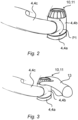
- the Fig. 2 shows, in a slightly modified form with respect to the shape of the robot arm, a partial view of the hand member 4b, as it can be pivoted or rotated about the pivot axis S in the direction of arrow P1.
- the additional output member 10 and the hand guide means 11 are arranged opposite the tool flange 8.
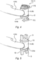
- the hand guide means 11 can be designed to be removable from the handle 4b, so that an additional tool 9 can be coupled to the handle 4b or to the additional output member 10 instead of the hand guide means 11. This is particularly Fig. 5 shown in more detail.
- the hand guide means 11 can, as shown in Fig. 3 As indicated, they have gripping sections 12 which, as shown, are arranged on an annular surface of the hand-guiding means 11, so that the hand-guiding means 11 can be gripped and rotated with the fingers of a person's hand 13.
- the robot arm 2 can generally be adjusted in its joint angle positions on the hand-guiding means 11 by guiding it with the hand 13.
- the hand-guide means 11 on the additional output member 10 can be configured such that by rotating the hand-guide means 11 in the direction of arrow P2, the tool flange 8 executes a correspondingly coupled rotational movement in the direction of arrow P3.
- the rotation of the hand-guide means 11 can be converted into an identical rotational movement of the tool flange 8, or a transmission in the rotational speed or angular velocity It is also possible for the tool flange 8 to perform a rotational movement opposite to the rotation of the hand-guide means 11, but in this case, depending on the adjustment of the hand-guide means 11, either synchronously or asynchronously.
- a gear 14 can be arranged within the hand member 4b, which is designed to couple the additional output member 10 to the distal end member 4a in order to convert a movement of the distal end member 4a into a movement of the additional output member 10 and/or to convert a movement of the additional output member 10 into a movement of the distal end member 4a.
- the gear 14 can, as shown, comprise a shaft 15, which is designed to transmit a torque between the additional output member 10 and the distal end member 4a or the tool flange 8.
- the gear 14 can comprise a switchable clutch 16, which, in an engaged state, is designed to transmit a torque between the additional output member 10 and the distal end member 4a and, in a disengaged state, to interrupt a transmission of a torque between the additional output member 10 and the distal end member 4a.
- a motor M1 can be integrated into the hand member 4b.
- a first drive device 6.1 can be assigned to the distal end member 4a, which is designed to automatically move the distal end member 4a, wherein a second drive device 6.2, different from the first drive device 6.1, is assigned to the additional output member 10 or the hand-guiding means 11, which second drive device is designed to move the additional output member 10 or the hand-guiding means 11. Consequently, the hand-guiding means 11 thereby having a force feedback device.
- the first drive device 6.1 can have a first motor M1
- the second drive device 6.2 can have a second motor M2, wherein the first motor M1 and the second motor M2 can be controlled independently of one another, for example, by the control device 3.
- At least one first position sensor 17.1 which is designed to detect the rotational position of the distal end member 4a, can be assigned to the distal end member 4a, i.e. the tool flange 8, and at least one second position sensor 17.2, which is designed to detect the rotational position of the additional output member 10, can be assigned to the additional output member 10.
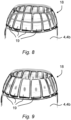
- the hand-guiding means 11 can have one or more input means 18, which are designed for manually inputting control commands into a control device 3 controlling the robot arm 2.
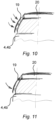
- the Fig. 10 shows an example of an input means 18 designed as a rocker switch and Fig. 11 shows an example of an input device 18 designed as a button.
- the combined hand guide means 11 and input means which is positioned in the swivel housing of the robot hand 4b between the last and the penultimate distal axis of the robot arm 2, can accordingly form a support surface for the hand 13, through which the user can ergonomically guide the robot arm by hand and can move the first n-1 axes of the n-axis robot arm directly in a force-controlled manner.
- the preferably ring-shaped, rotatable input field can be used to digitally and directly specify the movement of the distal end member 4a, i.e., the tool flange 8, from the hand member 4b, whereby appropriate feedback can optionally be transmitted back to the user via the hand 18.
- the following points make operating the last rotation axis particularly direct and natural.
- the ring can be designed to rotate like a jog wheel and thus does not need to have a centering center position.
- the ring can be frictional, i.e., have a dampened behavior or include a segmented grid that the user perceives haptically when turning.
- this restraining moment can be controlled and changed in order to obtain direct force feedback from the actual last axis, for example, in the event of a collision of the tool 19 ( Fig. 5 ) or when the axis limits of the joints of the robot arm 2 are reached.
- the manual control device 11 or the input device can be configured as an enabling button.
- the presented operating concept represents a holistic approach in which the user should be able to manually control the robot arm 2 with only one hand. Therefore, depending on the robot type, hazard potential and regulations, an enabling button can also be used for Manual movement may be necessary.
- a switch or pushbutton element can be placed on the input ring. For example, by gently pressing the ring together, movement can be enabled; by turning it, the last axis (joint of robot arm 2) can be controlled; and by moving the handrest, the rest of the robot can be moved.
- Touch-sensitive buttons such as capacitive or inductive ones, are also possible.
- buttons 19 in ring form e.g. laid switching strips or individual switching elements, such as buttons, can be provided, which can also be placed under a ring of touch segments and can be actuated by this when pressed.
- buttons 19 can be moved individually, analogous to keys on a computer keyboard, or tilted individually ( Fig. 10 and Fig. 11 ) and act on the button.
- a design is also possible in which the buttons 19 are made of a flexible material, e.g., plastic or elastomer, and both the connections between them and the guide functions and the buttons 19 are directly integrated by means of a suitable shape and a targeted stiffness distribution.
- the hand-guiding means 11 may have at least one display means 20 which is designed to optically display states of the robot arm 2 and/or the control device 3 on the hand-guiding means 11.
- the display means 20 can, for example, comprise an LED ring.
- An LED ring which can be controlled segment-by-segment, can visualize the inputs via the control ring.
- the LED ring's light sources can, for example, be assigned individually or in groups to individual input means or buttons.
- a display serving as the display means 20 can clearly show 0-100% settings, e.g., speed values, and/or angle settings, e.g., axis angle values. Likewise, general information such as a status can be clearly displayed.
- a central display can be provided optionally or alternatively, which can show essential information and, for example, in combination with an LED ring and operating ring as well as an enabling button, represents a novel, intuitive but also very puristic operating concept.
- the adjustment ring can be used to scroll through a menu on the display, set a value, or select a function. Briefly pressing the enabling button selects the program or menu item. Likewise, the "back" option can be selected or a gesture control can be used; for example, briefly touching the robot structure then means "back.”
- the ring's movement can normally be transmitted 1:1 to the flange axis. If necessary, a "digital translation" can also change the movement to slow or fast.
Landscapes
- Engineering & Computer Science (AREA)
- Robotics (AREA)
- Mechanical Engineering (AREA)
- Physics & Mathematics (AREA)
- General Physics & Mathematics (AREA)
- Automation & Control Theory (AREA)
- Manipulator (AREA)
Description
- Die Erfindung betrifft einen Roboterarm mit mehreren Gelenken und mehreren Gliedern, die durch die Bewegungen der Gelenke des Roboterarms gegeneinander verstellbar sind, wobei jedem angetriebenen Gelenk eine Antriebsvorrichtung zugeordnet ist und die jeweilige Antriebsvorrichtung ausgebildet ist, das ihr zugeordnete Gelenk des Roboterarms zu verstellen und zwar durch jeweiliges automatisches Ansteuern eines Motors der jeweiligen Antriebsvorrichtung, aufweisend ein als Werkzeugflansch ausgebildetes distales Endglied, ein dem distalen Endglied in der kinematischen Kette der Gelenke und Glieder unmittelbar vorgelagertes Handglied, an dem das distale Endglied um eine Flanschdrehachse drehbar gelagert ist.
- Die
WO 2015/078585 A2 beschreibt einen Roboterarm mit wenigstens zwei gegeneinander beweglichen Armmodulen und wenigstens einem manuell betätigbaren Eingabemodul zur Generierung von Steuersignalen zur Steuerung des Roboterarms auf Grundlage einer Benutzereingabe, bei dem beide Armmodule eine erste Schnittstelle aufweisen, an der das Eingabemodul wahlweise montierbar ist. - Die
EP 1 671 755 A1 beschreibt einen horizontal gelenkten Roboter mit einem oberen und unteren Endeffektor-Befestigungsteil. Dieser Roboter ist so konzipiert, dass er verschiedene Arbeitsformen und Werkstücke durch die selektive Nutzung der oberen und unteren Seiten einer Arbeitsspindel bewältigen kann. - Aufgabe der Erfindung ist es, einen Roboterarm zu schaffen, der einen erweiterten Nutzumfang aufweist.
- Die Aufgabe wird gelöst durch einen Roboterarm mit mehreren Gelenken und mehreren Gliedern, die durch die Bewegungen der Gelenke des Roboterarms gegeneinander verstellbar sind, wobei jedem angetriebenen Gelenk eine Antriebsvorrichtung zugeordnet ist und die jeweilige Antriebsvorrichtung ausgebildet ist, das ihr zugeordnete Gelenk des Roboterarms zu verstellen und zwar durch jeweiliges automatisches Ansteuern eines Motors der jeweiligen Antriebsvorrichtung, aufweisend ein als Werkzeugflansch ausgebildetes distales Endglied, ein dem distalen Endglied in der kinematischen Kette der Gelenke und Glieder unmittelbar vorgelagertes Handglied, an dem das distale Endglied um eine Flanschdrehachse drehbar gelagert ist, sowie ein am Handglied um eine zur Flanschdrehachse parallelen Drehachse drehbar gelagertes Zusatzabtriebsglied, welches dem distalen Endglied gegenüberliegend am Handglied angeordnet ist, wobei dem distalen Endglied eine erste Antriebsvorrichtung zugeordnet ist, welche ausgebildet ist zum Bewegen des distalen Endglieds und dem Zusatzabtriebsglied (10) eine von der ersten Antriebsvorrichtung verschiedene zweite Antriebsvorrichtung zugeordnet ist, welche ausgebildet ist zum Bewegen des Zusatzabtriebsglieds.
- Ein oder mehrere der Gelenke, insbesondere alle Gelenke des Roboterarms können als Drehgelenke ausgebildet sein. Jedes Glied des Roboterarms verbindet zwei benachbarte Gelenke des Roboterarms in einer festen relativen Zuordnung der Positionen und Orientierungen der benachbarte Gelenke zueinander. Jedes Glied des Roboterarms kann einteilig oder mehrteilig ausgeführt sein.
- Die Antriebsvorrichtungen können von einer Robotersteuerung insbesondere wahlweise gemäß eines Roboterprogramms automatisiert oder in einem Handfahrbetrieb des Roboters manuell über eine Eingabevorrichtung betätigt antriebsgesteuert bzw. alternativ auch in einem kraft-/momentgeregelten Betrieb des Roboterarms durch manuelles Führen des Roboterarms durch Anfassen und Bewegen wenigstens eines seiner Glieder verstellbar sein. Die jeweilige Antriebsvorrichtung kann von einem ansteuerbaren Motor gebildet werden. Die jeweilige Antriebsvorrichtung kann insbesondere einen elektrischen Motor umfassen. Die Antriebsvorrichtung kann neben dem eigentlichen Motor zur Erzeugung eines Drehmoments, zusätzlich ein Getriebe und/oder eine Antriebssteuereinrichtung umfassen. Die Antriebsvorrichtung kann ausgebildet sein zu einem geregelten Betrieb des Motors. Dazu kann die Antriebsvorrichtung, insbesondere die Antriebssteuereinrichtung eine Regeleinrichtung, insbesondere eine elektrische Regeleinrichtung aufweisen.
- Der Werkzeugflansch bildet ein Kopplungsmittel, an dem Roboterwerkzeuge, die durch den Roboterarm gehalten, bewegt, geführt und gegebenenfalls auch angesteuert werden, an dem Roboterarm befestigt werden können. Das Roboterwerkzeug kann beispielsweise ein Greifer sein, welcher ausgebildet ist zum Ergreifen eines Objektes, das durch Bewegen des Roboterarms gehandhabt werden soll. Alternativ kann das Roboterwerkzeug auch ein Bearbeitungswerkzeug sein, wie beispielsweise eine Schweißzange, ein sonstiges Werkzeug, insbesondere zur mechanischen Bearbeitung oder Handhabung eines Werkstücks. Der Werkzeugflansch kann insbesondere ein Flansch mit einem Flanschbild gemäß ISO 9409-1:2004-03 sein. Der Werkzeugflansch kann auch als mechanische Schnittstelle des Roboterarms bezeichnet werden.
- Als distales Endglied wird dasjenige Glied des Roboterarms verstanden, welches in der kinematischen Kette der mehreren Glieder und Gelenke des Roboterarms von seiner Basis, dem Grundgestell, am weitesten entfernt ist. Insofern kann die Basis, d.h. das Grundgestell des Roboterarms auch als proximales Endglied bezeichnet werden. Die kinematische Kette der mehreren Glieder und Gelenke des Roboterarms wird üblicherweise ausgehend von der Basis, d.h. ausgehend von dem Grundgestell in Richtung des distalen Endglieds, d.h. dem Handflansch des Roboterarms aufgereiht bzw. gezählt. Insofern sind sämtliche der Basis bzw. dem Grundgestell folgende Glieder der Basis bzw. dem Grundgestell nachgelagert. Sämtliche vom distales Endglied, d.h. vom Handflansch des Roboterarms verschiedenen Glieder des Roboterarms sind insofern dem distalen Endglied bzw. dem Handflansch des Roboterarms vorgelagert. Das in der kinematischen Kette vorletzte Glied des Roboterarms ist dem distalen Endglied bzw. dem Handflansch des Roboterarms insoweit unmittelbar vorgelagert und bildet das Handglied. Im Falle eines Knickarmroboters mit einer kinematischen Kette von seriell abwechselnd aufeinander folgenden sieben Gliedern und sechs Gelenken, wird das dem distalen Endglied (siebtes Glied) bzw. dem Handflansch des Roboterarms unmittelbar vorgelagert Glied als sechstes Glied bezeichnet. Die Basis bzw. das Grundgestell des Roboterarms bildet insoweit das erste Glied des Roboterarms. Das in der kinematischen Kette vorletzte Glied des Roboterarms wird in diesem Fall also unmittelbar von dem fünften Gelenk verstellt und bildet das Handglied. Im Falle eines Knickarmroboters mit einer kinematischen Kette von seriell abwechselnd aufeinander folgenden acht Gliedern und sieben Gelenken, wird das dem distalen Endglied (achtes Glied) bzw. dem Handflansch des Roboterarms unmittelbar vorgelagert Glied als siebtes Glied bezeichnet. Die Basis bzw. das Grundgestell des Roboterarms bildet insoweit das erste Glied des Roboterarms. Das in der kinematischen Kette vorletzte Glied des Roboterarms wird in diesem Fall also unmittelbar von dem sechsten Gelenk verstellt und bildet das Handglied.
- An dem Handglied ist das distale Endglied, das den Werkzeugflansch bildet, um seine Flanschdrehachse mittels eines Drehgelenks drehbar gelagert.
- Das Handglied weist erfindungsgemäß ein um eine zur Flanschdrehachse parallelen Drehachse drehbar gelagertes Zusatzabtriebsglied auf, welches dem distalen Endglied gegenüberliegend am Handglied angeordnet ist.
- Das Zusatzabtriebsglied ist ein vom Werkzeugflansch verschiedenes Abtriebsglied, welches an dem Handglied drehbar gelagert ist, und zwar drehbar um eine zur Flanschdrehachse parallelen Drehachse, und außerdem aktiv verstellbar, d.h. aktiv drehbar ist. Ein aktives Drehen des Zusatzabtriebsglieds kann durch einen dem Zusatzabtriebsglied eigens zugeordneten separaten Antrieb bzw. Motor erfolgen, oder durch einen der Antriebsvorrichtungen der Gelenke des Roboterarms, insbesondere durch diejenige Antriebsvorrichtung, welche den Werkzeugflansch antreibt und/oder das Handglied unmittelbar antreibt.
- Der Roboterarm kann eine solche mechanische Konfiguration aufweisen, dass die Flanschdrehachse des Werkzeugflansches stets parallel zur Drehachse des Zusatzabtriebsglieds und/oder eines Handführungsmittels verläuft, insbesondere die Flanschdrehachse des Werkzeugflansches und die Drehachse des Zusatzabtriebsglieds bzw. des Handführungsmittels stets auf derselben Geraden liegen, und dabei eine Schwenkachse, um welche das Handglied an einem dem Handglied in der kinematischen Kette unmittelbar vorgelagerten Armglied des Roboterarms drehbar gelagert ist, stets senkrecht zur Flanschdrehachse des Werkzeugflansches und zur Drehachse des Zusatzabtriebsglieds bzw. des Handführungsmittels orientiert angeordnet ist.
- Über das antreibbare Zusatzabtriebsglied kann ein Drehmoment auf ein mit dem Zusatzabtriebsglied gekoppeltes Funktionselement ausgeleitet werden. Ergänzend kann aufgrund der Koppelung von Zusatzabtriebsglied und Funktionselement auch ein Drehmoment über das Funktionselement hinweg auf das Zusatzabtriebsglied eingeleitet werden.
- In einer ersten Ausgestaltung kann das Funktionselement eine manuelle Schnittstelle sein. Die manuelle Schnittstelle kann ein Handführungsmittel, insbesondere eine Handauflage und/oder einen Griff aufweisen. Mittels des Handführungsmittels, der Handauflage und/oder dem Griff kann ein Benutzer des Roboterarms das Handführungsmittel, die Handauflage und/oder den Griff anfassen bzw. umgreifen, und beispielsweise in einem kraft-/momentgeregelten Betrieb des Roboterarms durch manuelles Führen des Roboterarms während des Anfassens der Handauflage und/oder des Griffes und folglich durch Bewegen wenigstens eines der Glieder des Roboterarms diesen verstellen. Aufgrund der Antreibbarkeit des Zusatzabtriebsglieds, an welches das Funktionselement angekoppelt ist, kann auch das Handführungsmittel, die Handauflage bzw. der Griff aktiv angetrieben werden, um dem Benutzer, welcher das Handführungsmittel, die Handauflage bzw. den Griff anfasst bzw. umgreift, ein taktiles Feedback zu geben.
- Das Handführungsmittel ermöglicht eine intuitives Handführen aller Freiheitsgrade des Roboterarms an einer großzügig dimensionierten Handauflagefläche, die jedoch anders als beim Stand der Technik, weder die Nutzlast wegen eines größeren effektiven Flanschabstands reduziert noch die distale Störkontur nachteilig beeinflusst. Diese Bedienschnittstelle ermöglicht sowohl ein direktes Handführen des Roboterarms (in einem Handführmodus) als auch (in einem anderen Modus) als Eingabeelement die Eingabe von Befehlen und Einstellungen am Roboter bzw. an der Robotersteuerung (Eingabemodus).
- In einer zweiten Ausgestaltung kann das Funktionselement ein manuelles Eingabemittel sein. Das Funktionselement kann ein oder mehrere Eingabemittel aufweisen. Jedes Eingabemittel kann als ein einziges Einzel-Eingabeelement zur Steuerung einer Einzelfunktion ausgebildet sein. Alternativ kann das Eingabemittel als ein Multi-Eingabeelement zur Steuerung mehrerer Einzelfunktion ausgebildet sein oder mehrere Einzel-Eingabeelemente umfassen, wobei jedes der mehrere Einzel-Eingabeelemente zur Steuerung einer Einzelfunktion ausgebildet sein kann.
- Das Funktionselement kann eine Kombination aus einer manuellen Schnittstelle, bzw. einem Handführungsmittel, einer Handauflage und/oder eines Griffes, und wenigstens eines manuelles Eingabemittels sein. Insofern kann aufgrund der Antreibbarkeit des Zusatzabtriebsglieds, an welches das Funktionselement angekoppelt ist, auch das manuelle Eingabemittel aktiv angetrieben werden, um dem Benutzer, welcher das manuelle Eingabemittel momentan betätigt, ein taktiles Feedback bei der manuellen Eingabe zu geben.
- In einer dritten Ausgestaltung kann das Funktionselement ein Zusatzwerkzeug sein. Das Zusatzabtriebsglied bildet in dieser Ausgestaltung ein zusätzliches Kopplungsmittel, an dem zusätzliche Roboterwerkzeuge, die durch den Roboterarm gehalten, bewegt, geführt und gegebenenfalls auch angesteuert werden können, an dem Roboterarm befestigt werden können. Das zusätzliche Roboterwerkzeug kann beispielsweise ein zusätzlicher Greifer sein, welcher ausgebildet ist zum Ergreifen eines Objektes, das durch Bewegen des Roboterarms gehandhabt werden soll. Alternativ kann das Roboterwerkzeug auch ein zusätzliches Bearbeitungswerkzeug sein, wie beispielsweise eine Schweißzange, ein sonstiges Werkzeug, insbesondere zur mechanischen Bearbeitung oder Handhabung eines Werkstücks. Das Zusatzabtriebsglied kann einen zusätzlichen Werkzeugflansch aufweisen, der insbesondere ein zusätzlicher Flansch mit einem Flanschbild gemäß ISO 9409-1:2004-03 sein kann. Der zusätzliche Werkzeugflansch kann auch als zusätzliche mechanische Schnittstelle des Roboterarms bezeichnet werden.
- Die im Folgenden beschriebenen Weiterbildungen können wahlweise im Rahmen der ersten Ausgestaltung, der zweiten Ausgestaltung und/oder der dritten Ausgestaltung zur Anwendung kommen.
- Innerhalb des Handglieds kann ein Getriebe angeordnet sein, welches ausgebildet ist, das Zusatzabtriebsglied an das distale Endglied anzukoppeln, um eine Bewegung des distalen Endglieds in eine Bewegung des Zusatzabtriebsglieds umzusetzen und/oder um eine Bewegung des Zusatzabtriebsglieds in eine Bewegung des distalen Endglieds umzusetzen.
- Das Getriebe kann eine einfache mechanische Koppel sein, welche die Bewegung des distale Endglieds unmittelbar in eine gleichförmige Bewegung des Zusatzabtriebsglieds umsetzt. Das Getriebe kann beispielsweise eine einfache Welle sein, in welche ein Drehmoment durch das distale Endglied eingeleitet, durch die Welle weitergeleitet und an das Zusatzabtriebsglied ausgeleitet wird.
- Das Getriebe kann eine Welle umfassen, welche ausgebildet ist zur Übertragung eines Drehmoments zwischen dem Zusatzabtriebsglied und dem distalen Endglied. In einer einfachen Ausführung kann die Welle an ihrem einen Wellenende an dem distalen Endglied festgelegt sein und an ihrem gegenüberliegenden anderen Wellenende an dem Zusatzabtriebsglied festgelegt sein. So kann eine Drehbewegung des distalen Endglieds direkt in eine gleichförmige Bewegung des Zusatzabtriebsglieds umgesetzt werden. In gleicher Weise kann dann auch eine Drehbewegung des Zusatzabtriebsglieds direkt in eine gleichförmige Bewegung des distalen Endglieds umgesetzt werden, wenn an das Zusatzabtriebsglied eine manuelle Schnittstelle, bzw. eine Handauflage und/oder ein Griff angeschlossen ist, welche manuell durch die Hand eines Benutzers gedreht werden kann, um das distale Endglied dadurch manuell zu verstellen.
- Das Getriebe kann aber auch wenigstens eine Übersetzungsstufe aufweisen, durch welche ein Übersetzungsverhältnis geschaffen werden kann, derart, dass trotz mechanischer Kopplung von distalem Endglied und Zusatzabtriebsglied, das Zusatzabtriebsglied bei Drehbewegung eine andere Drehzahl aufweist als die jeweilige Drehzahl des distalen Endglieds. Das Übersetzungsverhältnis kann größer als 1 sein. Alternativ kann das Übersetzungsverhältnis kleiner als 1 sein.
- Das Getriebe kann eine schaltbare Kupplung umfassen, welche ausgebildet ist in einem eingerückten Zustand ein Drehmoment zwischen dem Zusatzabtriebsglied und dem distalen Endglied zu übertragen und in einem ausgerückten Zustand eine Übertragung eines Drehmoments zwischen dem Zusatzabtriebsglied und dem distalen Endglied zu unterbrechen.
- Die schaltbare Kupplung kann manuell schaltbar sein. Dazu kann an dem Handglied eine Betätigungseinrichtung angeordnet sein, welche manuell, beispielsweise von einer Hand eines Benutzers, betätigt werden kann, um die Kupplung zu schalten. Die Betätigungseinrichtung kann ausgebildet sein die Kupplung mechanisch zu schalten. Alternativ oder ergänzend kann die Betätigungseinrichtung ausgebildet sein, die Kupplung durch eine Antriebseinrichtung angetrieben zu schalten, und zwar angesteuert durch die manuell zu betätigende Betätigungseinrichtung.
- Alternativ kann die schaltbare Kupplung angesteuert von einer den Roboterarm ansteuernden Robotersteuerung automatisch geschalten werden.
- Dem distalen Endglied kann eine erste Antriebsvorrichtung zugeordnet sein, welche ausgebildet ist zum Bewegen des distalen Endglieds und dem Zusatzabtriebsglied kann dabei eine von der ersten Antriebsvorrichtung verschiedene zweite Antriebsvorrichtung zugeordnet sein, welche ausgebildet ist zum Bewegen des Zusatzabtriebsglieds.
- In einer ersten Ausführungsform kann die zweite Antriebsvorrichtung, die dem Zusatzabtriebsglied zugeordnet ist, unabhängig von der ersten Antriebsvorrichtung, die dem distalen Endglied zugeordnet ist, angesteuert werden. Ein solches Ansteuern der erste Antriebsvorrichtung und der zweiten Antriebsvorrichtung kann durch die Robotersteuerung erfolgen.
- In einer zweiten Ausführungsform kann die zweite Antriebsvorrichtung, die dem Zusatzabtriebsglied zugeordnet ist, in Abhängigkeit von der ersten Antriebsvorrichtung, die dem distalen Endglied zugeordnet ist, angesteuert werden. Ein solches Ansteuern der erste Antriebsvorrichtung und der zweiten Antriebsvorrichtung kann durch die Robotersteuerung erfolgen. Insoweit kann die Robotersteuerung ausgebildet und eingerichtet sein, sowohl die erste Antriebsvorrichtung anzusteuern als auch die zweite Antriebsvorrichtung anzusteuern, derart, dass das distale Endglied und das Zusatzabtriebsglied synchrone Bewegungen ausführen. Die Robotersteuerung kann insbesondere ausgebildet und eingerichtet sein, durch das Ansteuern von distalem Endglied und/oder Zusatzabtriebsglied ein virtuelles Übersetzungsverhältnis zu simulieren, bei dem das Zusatzabtriebsglied bei Drehbewegung eine andere Drehzahl aufweist als die jeweilige Drehzahl des distalen Endglieds. Das virtuelle Übersetzungsverhältnis kann größer als 1 sein. Alternativ kann das virtuelle Übersetzungsverhältnis kleiner als 1 sein
- Die erste Antriebsvorrichtung kann einen ersten Motor aufweisen und die zweite Antriebsvorrichtung kann dabei einen zweiten Motor aufweisen, wobei der erste Motor und der zweite Motor durch eine Steuervorrichtung, beispielsweise die Robotersteuerung des Roboterarms, in Abhängigkeit voneinander ansteuerbar sind.
- Dem distalen Endglied kann wenigstens ein erster Stellungssensor zugeordnet sein, welche ausgebildet ist zum Erfassen der Drehstellung des distalen Endglieds und dem Zusatzabtriebsglied kann dabei wenigstens ein zweiter Stellungssensor zugeordnet sein, welche ausgebildet ist zum Erfassen der Drehstellung des Zusatzabtriebsglieds.
- Der erste Stellungssensor und der zweite Stellungssensor können steuerungstechnisch mit der Steuervorrichtung bzw. mit der Robotersteuerung des Roboterarms verbunden sein, so dass die Robotersteuerung in Abhängigkeit der erfassten Sensorwerte des ersten Stellungssensors und des zweiten Stellungssensors die erste Antriebsvorrichtung und/oder die zweite Antriebsvorrichtung entsprechend dem gewünschten Verhalten des distalen Endglieds und/oder des Zusatzabtriebsglieds ansteuern kann.
- Mit dem Zusatzabtriebsglied kann ein am Handglied angeordnetes Handführungsmittel verbunden sein, derart, dass durch manuelles Betätigen des Handführungsmittels das Zusatzabtriebsglied verstellbar ist und/oder durch automatisches Antreiben des Zusatzabtriebsglieds das Handführungsmittel automatisch verstellbar ist.
- In einer ersten Variante des Handführungsmittels kann dieses einen am Handglied drehbar gelagerten Drehsteller aufweisen, der einen Ring mit einer Umfangsringfläche und eine von der Umfangsringfläche eingegrenzte Stirnfläche aufweist. Die Stirnfläche kann zumindest weitgehend oder vollständig flach ausgebildet sein. Die Stirnfläche des Drehstellers kann sich zumindest im Wesentlichen und genau parallel zur Flanschebene des Werkzeugflansches erstrecken. Dabei weist die Oberfläche der Stirnfläche des Drehstellers in eine zur Oberfläche des Werkzeugflansches entgegengesetzte Richtung. Eine drehbare Lagerung des Drehstellers an dem Handglied kann entweder dadurch erfolgen, dass der Drehsteller an einem Gehäusebauteil des Handglieds drehbar gelagert ist. Alternativ kann eine drehbare Lagerung des Drehstellers an dem Handglied dadurch erreicht werden, indem der Drehsteller an dem Zusatzabtriebsglied befestigt ist, wobei demgemäß das Zusatzabtriebsglied innerhalb des Handglieds drehbar gelagert ist. Der Drehsteller kann manuell lösbar und wiederaufsteckbar an dem Zusatzabtriebsglied angekoppelt sein.
- In einer zweiten Variante des Handführungsmittels kann der Drehsteller eine Rasteinrichtung aufweisen, welche für gleichmäßig beabstandete Winkellagen des Drehstellers jeweils eine Raststellung vorgibt, die bei Drehen des Drehstellers erst bei Überwinden einer vorbestimmten Mindestauslösekraft verlassen werden kann, um eine benachbarte Raststellung überspringen zu können.
- Das Handführungsmittel kann manuell lösbar an dem Handglied oder dem Zusatzabtriebsglied befestigt sein und das Zusatzabtriebsglied kann dabei ein Werkzeugkupplungsmittel aufweisen, an das ein Zusatzwerkzeug ankoppelbar ist, wobei in einem befestigten Zustand des Handführungsmittels an dem Handglied oder dem Zusatzabtriebsglied das Werkzeugkupplungsmittel durch das Handführungsmittel verdeckt ist und in einem entfernten Zustand des Handführungsmittels von dem Handglied oder dem Zusatzabtriebsglied das Werkzeugkupplungsmittel zum Ankoppeln eines Werkzeugs zugänglich ist.
- Aufgrund des Werkzeugkupplungsmittels kann wahlweise ein Handführungsmittel oder ein Zusatzwerkzeug an dem Zusatzabtriebsglied angekoppelt werden. Ist das Zusatzwerkzeug von dem Zusatzabtriebsglied entfernt, kann das auf das Zusatzabtriebsglied aufgesteckte Handführungsmittel ergänzend ein Sicherungsmittel bilden, das ein unerwünschtes manuelles Eingreifen in das Zusatzabtriebsglied verhindert, insbesondere wenn das Zusatzabtriebsglied in Bewegung ist. Das Handführungsmittel muss dabei insoweit nicht notwendiger Weise an das Zusatzabtriebsglied angekoppelt sein, sondern kann vielmehr lediglich an einem Gehäuseabschnitt des Handglieds befestigt sein. Das Handführungsmittel hat dann auch die Funktion einer Abdeckkappe.
- Das Handführungsmittel kann einen Griffabschnitt oder einen Griff mit wenigstens einem Griffabschnitt aufweisen, der zum manuellen Führen des Roboterarms mittels einer Hand eines Benutzers ausgebildet ist. Das Handführungsmittel kann demgemäß ein vorspringendes Griffglied aufweisen, welches von einer Hand eines Benutzers gegriffen werden kann, um durch Bewegen des mit der Hand erfassten Griffgliedes das Handglied des Roboterarms zu bewegen und folglich die Gelenkwinkelstellungen des Roboterarms verändern zu können.
- Das Handführungsmittel kann aber auch einen Griffabschnitt aufweisen, der nicht vorspringt, sondern im Wesentlichen on einer Oberfläche des Handführungsmittels gebildet wird.
- In einer ersten Variante des Griffabschnitts kann dieser von einer strukturierten Oberfläche einer Ringfläche des Handführungsmittels gebildet werden.
- In einer zweiten Variante des Griffabschnitts kann die strukturierte Oberfläche von mehreren diskreten Erhebungen an der Ringfläche des Handführungsmittels gebildet werden. Die mehreren diskreten Erhebungen können gleichmäßig über den Umfang der Ringfläche hinweg verteilt angeordnet sein. Die Form und Größe der Erhebungen können unter Beachtung ergonomischer Aspekte an die durchschnittliche Form und Größe von Fingern einer Hand eines Menschen angepasst sein. So können die mehreren diskreten Erhebungen derart ausgebildet sein, dass beim Ergreifen des Griffabschnitts mit der Hand einer Person jeweils eine Erhebung sich zwischen zwei benachbarte Finger einer Hand einfügen.
- In einer dritten Variante des Griffabschnitts kann die strukturierte Oberfläche von mehreren diskreten Vertiefungen in der Ringfläche des Handführungsmittels gebildet werden. Die mehreren diskreten Vertiefungen können gleichmäßig über den Umfang der Ringfläche hinweg verteilt angeordnet sein. Die Form und Größe der Vertiefungen können unter Beachtung ergonomischer Aspekte an die durchschnittliche Form und Größe von Fingern einer Hand eines Menschen angepasst sein. So können die mehreren diskreten Vertiefungen derart ausgebildet sein, dass beim Ergreifen des Griffabschnitts mit der Hand einer Person jeweils eine Fingerkuppe eines Fingers der Hand einer Person in eine Vertiefung eingreift.
- Alternativ oder ergänzend zu einem Griff oder Griffabschnitt kann das Handführungsmittel ein Eingabemittel aufweisen, das zum manuellen Eingeben von Steuerbefehlen in eine den Roboterarm ansteuernde Steuervorrichtung ausgebildet ist. Das Eingabemittel kann insbesondere ein elektrisches Eingabemittel, beispielsweise ein elektrischer Schalter oder ein elektrischer Taster sein, der einen elektrischen Schaltkreis schaltet, die mit der Robotersteuerung verbunden ist. So kann von einer den Roboterarm bedienenden Person über das Eingabemittel ein Eingabesignal an die Robotersteuerung übermittelt werden. Die Robotersteuerung führt dann eine dem Eingabemittel zugeordnete Funktion aus.
- In einer ersten Variante des Eingabemittels kann dieses wenigstens einen Taster oder Schalter an einer Stirnseite des Handführungsmittels umfassen.
- In einer zweiten Variante des Eingabemittels kann dieses wenigstens einen, insbesondere mehrere Taster oder Schalter an einer Ringfläche des Handführungsmittels umfassen. Im Falle von mehreren Tastern oder Schaltern an der Ringfläche des Handführungsmittels können diese in gleichmäßigen Abständen voneinander über den Umfang verteilt auf einer Oberfläche der Ringfläche des Handführungsmittels angeordnet sein. Die Anordnung der mehreren Taster oder Schalter auf der Ringfläche kann auf eine Anordnung von Erhebungen und/oder Vertiefungen als Griffabschnitte des Handführungsmittels abgestimmt sein, insbesondere kann jeder Erhebung und/oder Vertiefung ein einzelner Taster oder Schalter zugeordnet sein. Alternativ kann auch nur jeder beispielsweise zweiten Erhebung und/oder Vertiefung ein einzelner Taster oder Schalter zugeordnet sein.
- In einer dritten Variante des Eingabemittels kann das Handführungsmittel in axialer Richtung zu seiner Drehachse verstellbar gelagert sein und das Eingabemittel dadurch gebildet werden, dass das komplette Handführungsmittel in axialer Richtung gedrückt wird. Diesem axialen Drücken kann eine Tastfunktion zugeordnet sein, so dass ein Signal nur während der Dauer des Drückens erzeugt wird. Alternativ kann dem axialen Drücken des Handführungsmittels eine Umschaltfunktion zugeordnet sein, so dass durch einmaliges, insbesondere kurzes axiales Drücken des Handführungsmittels ein Schaltzustand aktiviert wird und bei einem nochmaligen kurzen axialen Drücken des Handführungsmittels der aktivierte Schaltzustand wieder deaktiviert wird.
- In einer vierten Variante des Eingabemittels kann diesem die Funktion einer Zustimmtaste zugeordnet sein. Die Funktion in Art einer Zustimmtaste kann analog einer Zustimmtaste an einem Bedienhandgerät eines Roboters ausgeführt sein, wie dies beispielsweise in EN ISO 10218-1:2011, insbesondere in Anhang C beschrieben ist.
- In einer fünften Variante des Eingabemittels kann diesem die Funktion einer Auswahltaste oder Eingabetaste (auch: Returntaste oder Entertaste) zugeordnet sein. In dieser Funktion dient das Eingabemittel als ein Bestätigungsmittel, um durch eine manuelle Bewegung mit der Hand einer Person eine steuerungstechnische Funktion der Robotersteuerung auszulösen oder eine bestimmte Auswahl aus mehreren Zustandsmöglichkeiten zu treffen, d.h. den zuvor ausgewählten Zustand zu bestätigen. Die Auswahl eines bestimmten Zustands aus mehreren Zustandsmöglichkeiten kann beispielsweise durch eine oder zwei Taster oder Schalter erfolgen, die konfiguriert sind zum Blättern bzw. Scrollen in einem Menü eines Anwenderprogramms, das mehrere Zustände zur Auswahl anzeigt.
- In einer sechsten Variante des Eingabemittels kann demgemäß die wenigstens eine Taste oder Schalter ein Eingabemittel sein, durch welches Scroll-Funktion ausgeführt werden kann, so dass in einem Menü eines Anwenderprogramms, das mehrere Zustände zur Auswahl anzeigt, ein gewünschter Zustand durch einfaches oder mehrfaches Betätigen der Taste oder des Schalters angewählt werden kann.
- In einer siebten Variante des Eingabemittels kann das Eingabemittel durch einen Drehsteller gebildet werden, welcher einen um die Drehachse drehbaren Kopf aufweist, der mit den Fingern einer Hand betätigt werden kann. Der Drehsteller kann in Art eines Drehschalters in mehreren diskreten mechanischen Stufen schaltbar sein oder in Art eines Potentiometers mechanisch stufenlos ausgebildet sein. Jeder diskreten Schaltstufe und/oder bestimmten Winkelstellungen des Drehstellers kann ein separater Zustand zugeordnet sein. Durch einen solchen Drehsteller kann eine Scroll-Funktion abgebildet werden, so dass in einem Menü eines Anwenderprogramms, das mehrere Zustände zur Auswahl anzeigt, ein gewünschter Zustand durch entsprechendes Drehen des Drehstellers angewählt werden kann. Ergänzend kann durch Drücken des Drehstellers eine weitere Schaltfunktion realisiert werden, beispielsweise die Funktion einer Auswahltaste oder Eingabetaste, wie in Verbindung mit der fünften Variante des Eingabemittels beschrieben. Der Drehsteller kann insoweit einen sogenannten "Jog-Dial" bilden.
- Alternativ oder ergänzend zu einem Griffabschnitt und/oder einem Eingabemittel kann das Handführungsmittel wenigstens ein Anzeigemittel aufweisen, das zum optischen Anzeigen von Zuständen des Roboterarms und/oder der Steuervorrichtung an dem Handführungsmittel ausgebildet ist.
- In einer ersten Variante des Anzeigemittels kann ein elektronisches Display an der Stirnseite des Handführungsmittels ausgebildet sein. Auf dem Display können Werte von vorbestimmten Zustandsarten angezeigt werden. Die jeweilige angezeigte Zustandsart kann aus einer Menge an mehreren Zustandsarten manuell ausgewählt sein. Mittels eines als Drehstellers ausgebildeten Handführungsmittels kann auch diejenige Zustandsart manuell ausgewählt werden, deren momentaner Wert an dem Anzeigemittel dann dargestellt werden kann.
- In einer zweiten Variante des Anzeigemittels kann ein elektronisches Touch-Display an der Stirnseite des Handführungsmittels ausgebildet sein, das neben der Anzeigefunktion auch die Möglichkeit von manuellen Tasteingaben aufweist. Mittels des Touch-Displays können manuelle Eingaben direkt auf der Oberfläche an der Stirnseite des Handführungsmittels eingegeben werden.
- Konkrete Ausführungsbeispiele der Erfindung sind in der nachfolgenden Beschreibung unter Bezugnahme auf die beigefügten Figuren näher erläutert.
- Es zeigen:
- Fig. 1
- einen beispielhaften Roboterarm mit sieben Gelenken und acht Gliedern, sowie mit einer die Gelenke des Roboterarms ansteuernde Robotersteuerung,
- Fig. 2 bis 4
- schematische Darstellungen jeweils eines distalen Endbereichs eines beispielhaften Roboterarms mit einem erfindungsgemäßen Zusatzabtriebsglied in Form eines Handführungsmittels,
- Fig. 5
- eine schematische Darstellung eines distalen Endbereichs eines distalen Endbereichs eines beispielhaf- ten Roboterarms mit einem erfindungsgemäßen Zusatzabtriebsglied in Form eines Werkzeugkupplungsmittels mit einem Zusatzwerkzeug,
- Fig. 6 und 7
- je eine Schnittdarstellung durch ein Handglied eines Roboterarms und das darin gelagerte Zusatzabtriebsglied,
- Fig. 8
- eine vergrößerte Teilansicht eines Handglieds des Roboterarms im Bereich des Handführungsmittels mit mehreren Eingabemitteln,
- Fig. 9
- eine vergrößerte Teilansicht eines Handglieds des Roboterarms im Bereich des Handführungsmittels mit mehreren Anzeigemitteln,
- Fig. 10
- eine schematische Schnittdarstellung im Bereich eines als Schaltwippe ausgebildeten Eingabemittels,
- Fig. 11
- eine schematische Schnittdarstellung im Bereich eines als Taster ausgebildeten Eingabemittels, und
- Fig. 12 bis 14
- schematische Darstellungen von Handführungsmitteln am Handglied des Roboterarms, die stirnseitig jeweils Anzeigemittel aufweisen.
- In der
Fig. 1 ist ein Roboter 1 dargestellt mit einem Roboterarm 2 und einer den Roboterarm 2 ansteuernden Robotersteuerung 3. Der Roboterarm umfasst mehrere Gelenke 5 und mehreren Glieder 4, die durch die Bewegungen der Gelenke 5 des Roboterarms 2 gegeneinander verstellbar sind, wobei jedem angetriebenen Gelenk 5 eine Antriebsvorrichtung 6 zugeordnet ist und die jeweilige Antriebsvorrichtung 6 ausgebildet ist, das ihr zugeordnete Gelenk 5 des Roboterarms 2 zu verstellen und zwar durch jeweiliges automatisches Ansteuern eines Motors 7 der jeweiligen Antriebsvorrichtung 6, aufweisend ein als Werkzeugflansch 8 ausgebildetes distales Endglied 4a, ein dem distalen Endglied 4a in der kinematischen Kette der Gelenke 5 und Glieder 4 unmittelbar vorgelagertes Handglied 4b, an dem das distale Endglied 4a um eine Flanschdrehachse A drehbar gelagert ist, sowie ein am Handglied 4b um eine zur Flanschdrehachse A parallelen Drehachse D drehbar gelagertes Zusatzabtriebsglied 10 (Fig. 6 ), welches dem distalen Endglied 4a gegenüberliegend am Handglied 4b angeordnet ist. An dem Zusatzabtriebsglied 10 ist ein Handführungsmittel 11 angekoppelt. - Der Roboterarm 2 kann wie dargestellt eine solche mechanische Konfiguration aufweisen, dass die Flanschdrehachse A des Werkzeugflansches 8 stets parallel zur Drehachse D des Zusatzabtriebsglieds 10 und/oder des Handführungsmittels 11 verläuft, insbesondere die Flanschdrehachse A des Werkzeugflansches 8 und die Drehachse D des Zusatzabtriebsglieds 10 bzw. des Handführungsmittels 11 stets auf derselben Geraden liegen, und dabei eine Schwenkachse S, um welche das Handglied 4b an einem dem Handglied 4b in der kinematischen Kette unmittelbar vorgelagerten Armglied 4c des Roboterarms 2 drehbar gelagert ist, stets senkrecht zur Flanschdrehachse A des Werkzeugflansches 8 und zur Drehachse D des Zusatzabtriebsglieds 10 bzw. des Handführungsmittels 11 orientiert angeordnet ist.
- Die
Fig. 2 zeigt in einer hinsichtlich der Form des Roboterarms etwas abgewandelten Weise in einer Teildarstellung das Handglied 4b, wie es um die Schwenkachse S in Pfeilrichtung P1 geschwenkt bzw. gedreht werden kann. Dem Werkzeugflansch 8 gegenüberliegend ist das Zusatzabtriebsglieds 10 und das Handführungsmittel 11 angeordnet. - Das Handführungsmittel 11 kann von dem Handglied 4b abnehmbar ausgeführt sein, so dass an dem Handglied 4b bzw. an dem Zusatzabtriebsglied 10 statt des Handführungsmittels 11 ein Zusatzwerkzeug 9 angekoppelt werden kann. Dies ist insbesondere in
Fig. 5 näher dargestellt. - Das Handführungsmittel 11 kann jedoch, wie dies in
Fig. 3 angedeutet ist, Griffabschnitte 12 aufweisen, die wie dargestellt an einer Ringfläche des Handführungsmittel 11 angeordnet sind, so dass das Handführungsmittel 11 mit den Fingern einer Hand 13 einer Person gegriffen und gedreht werden kann. Alternativ oder ergänzend zu einem manuellen Drehen des Handführungsmittels 11 kann ganz allgemein der Roboterarm 2 an dem Handführungsmittel 11 in seinen Gelenkwinkelstellungen durch Führen mittels der Hand 13 verstellt werden. - Wie die
Fig. 4 aufzeigt, kann das Handführungsmittel 11 an dem Zusatzabtriebsglied 10 derart konfiguriert sein, dass durch ein Drehen des Handführungsmittels 11 um die Pfeilrichtung P2 der Werkzeugflansch 8 eine entsprechend gekoppelte Drehbewegung um die Pfeilrichtung P3 ausführt. Die Drehung des Handführungsmittels 11 kann in eine identische Drehbewegung des Werkzeugflansches 8 umgesetzt werden, oder eine Übersetzung in der Drehzahl bzw. der Winkelgeschwindigkeit aufweisen. Es ist auch möglich, dass der Werkzeugflansche 8 eine zur Drehung des Handführungsmittels 11 entgegengesetzte Drehbewegung ausführt, allerdings in diesem Fall dennoch in Abhängigkeit des Verstellens des Handführungsmittels 11, wahlweise synchron oder asynchron. - Die
Fig. 6 zeigt, dass innerhalb des Handglieds 4b ein Getriebe 14 angeordnet sein kann, welches ausgebildet ist, das Zusatzabtriebsglied 10 an das distale Endglied 4a anzukoppeln, um eine Bewegung des distalen Endglieds 4a in eine Bewegung des Zusatzabtriebsglieds 10 umzusetzen und/oder um eine Bewegung des Zusatzabtriebsglieds 10 in eine Bewegung des distalen Endglieds 4a umzusetzen. Das Getriebe 14 kann wie dargestellt eine Welle 15 umfassen, welche ausgebildet ist zur Übertragung eines Drehmoments zwischen dem Zusatzabtriebsglied 10 und dem distalen Endglied 4a bzw. dem Werkzeugflansch 8. Das Getriebe 14 kann eine schaltbare Kupplung 16 umfassen, welche ausgebildet ist in einem eingerückten Zustand ein Drehmoment zwischen dem Zusatzabtriebsglied 10 und dem distalen Endglied 4a zu übertragen und in einem ausgerückten Zustand eine Übertragung eines Drehmoments zwischen dem Zusatzabtriebsglied 10 und dem distalen Endglied 4a zu unterbrechen. Als Antriebsvorrichtung 6 kann ein Motor M1 in das Handglied 4b integriert sein. - Insofern kann dem distalen Endglied 4a eine erste Antriebsvorrichtung 6.1 zugeordnet sein, welche ausgebildet ist zum automatischen Bewegen des distalen Endglieds 4a, wobei dem Zusatzabtriebsglied 10 bzw. dem Handführungsmittel 11 eine von der ersten Antriebsvorrichtung 6.1 verschiedene zweite Antriebsvorrichtung 6.2 zugeordnet ist, welche ausgebildet ist zum Bewegen des Zusatzabtriebsglieds 10 bzw. des Handführungsmittels 11. Folglich kann das Handführungsmittel 11 dadurch eine Force-Feedback-Einrichtung aufweisen. Die erste Antriebsvorrichtung 6.1 kann insoweit einen ersten Motor M1 aufweisen und die zweite Antriebsvorrichtung 6.2 einen zweiten Motor M2 aufweisen, wobei der erste Motor M1 und der zweite Motor M2 beispielsweise durch die Steuervorrichtung 3 in Abhängigkeit voneinander ansteuerbar sein können.
- Dem distalen Endglied 4a, d.h. dem Werkzeugflansch 8 kann wenigstens ein erster Stellungssensor 17.1 zugeordnet sein, welche ausgebildet ist zum Erfassen der Drehstellung des distalen Endglieds 4a und dem Zusatzabtriebsglied 10 kann wenigstens ein zweiter Stellungssensor 17.2 zugeordnet sein, welche ausgebildet ist zum Erfassen der Drehstellung des Zusatzabtriebsglieds 10.
- In der
Fig. 7 ist schematisch aufgezeigt, dass aufgrund der schenkbaren Lagerung des Handglieds 4b an dem Armglied 4c um die Schwenkachs S wahlweise das distale Endglied 4a, d.h. der Werkzeugflansch 8 nach unten weisend ausgerichtet werden kann, wobei das Zusatzabtriebsglied 10 bzw. das Handführungsmittel 11 nach oben weist, oder es kann das distale Endglied 4a, d.h. der Werkzeugflansch 8 nach oben weisend ausgerichtet werden, wobei das Zusatzabtriebsglied 10 bzw. das Handführungsmittel 11 dann nach unten weist. - Wie die
Fig. 8 und Fig. 9 aufzeigen, kann das Handführungsmittel 11 ein oder mehrere Eingabemittel 18 aufweisen, die zum manuellen Eingeben von Steuerbefehlen in eine den Roboterarm 2 ansteuernde Steuervorrichtung 3 ausgebildet sind. DieFig. 10 zeigt beispielhaft ein als Schaltwippe ausgebildetes Eingabemittel 18 undFig. 11 zeigt beispielhaft ein als Taster ausgebildetes Eingabemittel 18. - Das kombinierte Handführungsmittel 11 und Eingabemittel, welches im Schwenkgehäuse der Roboterhand 4b zwischen der letzten und der vorletzten distalen Achse des Roboterarms 2 positioniert ist, kann demgemäß eine Auflagefläche für die Hand 13 bilden, durch welche der Benutzer ergonomisch günstig den Roboterarm handführen kann und die ersten n-1 Achsen des n-achsigen Roboterarms direkt kraftgeregelt bewegen kann.
- Das vorzugsweise ringförmige drehbare Eingabefeld kann dazu dienen, die Bewegung des distale Endglieds 4a, d.h. des Werkzeugflansches 8, vom Handglied 4b aus digital und direkt vorzugeben, wobei optional ein entsprechendes Feedback an den Nutzer über die Hand 18 zurückübermittelt werden kann. Das Bedienen der letzten Drehachse wird durch die folgenden Punkte als besonders direkt und natürlich empfunden.
- Der Ring kann durchdrehend in Art eines Jogwheels ausgebildet sein und muss somit keine zentrierende Mittelstellung besitzen. Zwecks präziser und bewusster Eingabe kann der Ring reibungsbehaftet sein, d.h. ein gedämpftes Verhalten aufweisen oder eine segmentweise Rasterung umfassen, die der Nutzer beim Drehen haptisch wahrnimmt. Dieses rückhaltende Moment kann in einer vorteilhaften Variante angesteuert veränderbar sein, um ein direktes Kraft-Feedback der realen letzten Achse zu erhalten, beispielsweise im Falle einer Kollision des Werkzeugs 19 (
Fig. 5 ) oder beim Erreichen der Achsgrenzen der Gelenke des Roboterarms 2. - Das Handführungsmittel 11 bzw. das Eingabemittel kann in Art eines Zustimmtasters konfiguriert sein. Das vorgestellte Bedienkonzept stellt einen ganzheitlichen Ansatz dar, bei dem der Nutzer in der Lage sein soll mit nur einer Hand den Roboterarm 2 handzuführen. Daher kann je nach Robotertyp, Gefährdungspotential und Vorschriften auch ein Zustimmtaster zum Handverfahren erforderlich machen. Damit eine Zustimmung bei gleichzeitiger Handführung möglich ist, kann beispielsweise ein Schalt- bzw. Tastelement auf dem Eingabering platziert werden. Durch leichtes Zusammendrücken des Ringes beispielsweise kann die Fahrfreigabe erteilt werden, durch Verdrehen kann die letzte Achse (Gelenk des Roboterarms 2) angesteuert und durch Verschieben der Handauflage, der restliche Roboter bewegt werden. Ebenso sind auch berührend wirkende Taster, beispielsweise kapazitiv oder induktiv, möglich.
- Als Ausführungsformen, wie in
Fig. 8 und Fig. 9 beispielhaft aufgezeigt ist, können ein oder mehrere zusammenhängende Schaltflächen 19 in Ringform, z.B. verlegte Schaltleisten oder einzelne Schaltelemente, wie Taster, vorgesehen sein, die beispielsweise auch unter einem Ring von Tastsegmenten platziert sein können und von diesem bei Druck betätigt werden können. - Die Schaltflächen 19 können dabei einzeln schiebend analog von Tasten einer Computer-Tastatur oder einzeln kippend (
Fig. 10 und Fig. 11 ) aufgehängt sein und auf den Taster wirken. Ebenso ist auch eine Ausführung möglich, bei denen die Schaltflächen 19 zusammenhängend aus einem nachgiebigen Material, z.B. Kunststoff wie Elastomer, hergestellt sind und sowohl die Verbindungen untereinander als auch die Führungsfunktionen und die Schaltflächen 19 durch eine geeignete Formgebung und eine gezielte Steifigkeitsverteilung direkt integriert werden. - Das Handführungsmittel 11 kann wenigstens ein Anzeigemittel 20 aufweisen, das zum optischen Anzeigen von Zuständen des Roboterarms 2 und/oder der Steuervorrichtung 3 an dem Handführungsmittel 11 ausgebildet ist.
- Das Anzeigemittel 20 kann beispielsweise einen LED-Ring umfassen. Ein beispielsweise segmentweise ansteuerbarer LED-Ring kann die Eingaben über den Bedienring visualisiert. Die Leuchtmittel des LED-Ring können beispielsweise einzeln oder in Gruppen jeweils einzelnen Eingabemittels bzw. Tastern zugeordnet sein. An einem Display als Anzeigemittel 20 lassen sich 0-100% Einstellungen, z.B. Geschwindigkeitswerte, und/oder Winkeleinstellungen, z.B. Achswinkelwerte sehr anschaulich darstellen. Ebenso sind allgemeine Informationen wie beispielsweise ein Status gut sichtbar anzeigbar.
- Ein zentrales Display kann optional oder alternativ vorgesehen sein, welches wesentliche Informationen anzeigen kann, und beispielsweise in Kombination mit LED-Ring und Bedienring sowie Zustimmtaster ein neuartiges, intuitives aber auch sehr puristisches Bedienkonzept darstellt.
- Wird das Bedienelement im Eingabemodus benutzt, kann mit dem Einstell-Ring z.B. durch ein Menü auf dem Display gescrollt oder ein Wert eingestellt oder eine Funktion ausgewählt werden. Eine kurze Betätigung des Zustimmtasters wählt den Programm- oder Menüpunkt aus. Ebenso kann auch die "zurück Option" gewählt werden oder eine Gestensteuerung gewählt werden, z.B. die Roboterstruktur kurz berühren bedeutet dann ein "zurück".
- Wird das Bedienelement im Handführmodus betrieben, kann die Bewegung des Ringes im Normalfall 1:1 zur Flanschachse durchgeleitet werden. Bei Bedarf kann eine "digitale Übersetzung" auch die Bewegung ins Langsame oder ins Schnelle ändern.
Claims (9)
- Roboterarm mit mehreren Gelenken (5) und mehreren Gliedern (4), die durch die Bewegungen der Gelenke (5) des Roboterarms (2) gegeneinander verstellbar sind, wobei jedem angetriebenen Gelenk (5) eine Antriebsvorrichtung (6) zugeordnet ist und die jeweilige Antriebsvorrichtung (6) ausgebildet ist, das ihr zugeordnete Gelenk (5) des Roboterarms (2) zu verstellen und zwar durch jeweiliges automatisches Ansteuern eines Motors (7) der jeweiligen Antriebsvorrichtung (6), aufweisend ein als Werkzeugflansch (8) ausgebildetes distales Endglied (4a), ein dem distalen Endglied (4a) in der kinematischen Kette der Gelenke (5) und Glieder (4) unmittelbar vorgelagertes Handglied (4b), an dem das distale Endglied (4a) um eine Flanschdrehachse (A) drehbar gelagert ist, sowie ein am Handglied (4b) um eine zur Flanschdrehachse (A) parallelen Drehachse (D) drehbar gelagertes Zusatzabtriebsglied (10), welches dem distalen Endglied (4a) gegenüberliegend am Handglied (4b) angeordnet ist, dadurch gekennzeichnet, dass dem distalen Endglied (4a) eine erste Antriebsvorrichtung (6.1) zugeordnet ist, welche ausgebildet ist zum Bewegen des distalen Endglieds (4a) und dem Zusatzabtriebsglied (10) eine von der ersten Antriebsvorrichtung (6.1) verschiedene zweite Antriebsvorrichtung (6.2) zugeordnet ist, welche ausgebildet ist zum Bewegen des Zusatzabtriebsglieds (10).
- Roboterarm nach Anspruch 1, dadurch gekennzeichnet, dass innerhalb des Handglieds (4b) ein Getriebe (14) angeordnet ist, welches ausgebildet ist, das Zusatzabtriebsglied (10) an das distale Endglied (4a) anzukoppeln, um eine Bewegung des distalen Endglieds (4a) in eine Bewegung des Zusatzabtriebsglieds (10) umzusetzen und/oder um eine Bewegung des Zusatzabtriebsglieds (10) in eine Bewegung des distalen Endglieds (4a) umzusetzen.
- Roboterarm nach Anspruch 2, dadurch gekennzeichnet, dass das Getriebe (14) eine Welle (15) umfasst, welche ausgebildet ist zur Übertragung eines Drehmoments zwischen dem Zusatzabtriebsglied (10) und dem distalen Endglied (4a).
- Roboterarm nach Anspruch 2 oder 3, dadurch gekennzeichnet, dass das Getriebe (14) eine schaltbare Kupplung (16) umfasst, welche ausgebildet ist in einem eingerückten Zustand ein Drehmoment zwischen dem Zusatzabtriebsglied (10) und dem distalen Endglied (4a) zu übertragen und in einem ausgerückten Zustand eine Übertragung eines Drehmoments zwischen dem Zusatzabtriebsglied (10) und dem distalen Endglied (4a) zu unterbrechen.
- Roboterarm nach Anspruch 1, dadurch gekennzeichnet, dass die erste Antriebsvorrichtung (6.1) einen ersten Motor (M1) aufweist und die zweite Antriebsvorrichtung (6.2) einen zweiten Motor (M2) aufweist, wobei der erste Motor (M1) und der zweite Motor (M2) durch eine Steuervorrichtung (3) in Abhängigkeit voneinander ansteuerbar sind.
- Roboterarm nach Anspruch 5, dadurch gekennzeichnet, dass dem distalen Endglied (4a) wenigstens ein erster Stellungssensor (17.1) zugeordnet ist, welche ausgebildet ist zum Erfassen der Drehstellung des distalen Endglieds (4a) und dem Zusatzabtriebsglied (10) wenigstens ein zweiter Stellungssensor (17.2) zugeordnet ist, welche ausgebildet ist zum Erfassen der Drehstellung des Zusatzabtriebsglieds (10).
- Roboterarm nach einem der Ansprüche 1 bis 6, dadurch gekennzeichnet, dass mit dem Zusatzabtriebsglied (10) ein am Handglied (4b) angeordnetes Handführungsmittel (11) verbunden ist, derart, dass durch manuelles Betätigen des Handführungsmittels (11) das Zusatzabtriebsglied (10) verstellbar ist und/oder durch automatisches Antreiben des Zusatzabtriebsglieds (10) das Handführungsmittel (11) automatisch verstellbar ist.
- Roboterarm nach Anspruch 7, dadurch gekennzeichnet, dass das Handführungsmittel (11) manuell lösbar an dem Handglied (4b) oder dem Zusatzabtriebsglied (10) befestigt ist und das Zusatzabtriebsglied (10) ein Werkzeugkupplungsmittel aufweist, an das ein Zusatzwerkzeug (9) ankoppelbar ist, wobei in einem befestigten Zustand des Handführungsmittels (11) an dem Handglied (4b) oder dem Zusatzabtriebsglied (10) das Werkzeugkupplungsmittel durch das Handführungsmittel (11) verdeckt ist und in einem entfernten Zustand des Handführungsmittels (11) von dem Handglied (4b) oder dem Zusatzabtriebsglied (10) das Werkzeugkupplungsmittel zum Ankoppeln eines Zusatzwerkzeugs (9) zugänglich ist.
- Roboterarm nach Anspruch 7 oder 8, dadurch gekennzeichnet, dass das Handführungsmittel (11) einen Griffabschnitt aufweist, der zum manuellen Führen des Roboterarms (2) mittels einer Hand (13) eines Benutzers ausgebildet ist, und wenigstens ein Eingabemittel (18) aufweist, das zum manuellen Eingeben von Steuerbefehlen in eine den Roboterarm (2) ansteuernde Steuervorrichtung (3) ausgebildet ist und wenigstens ein Anzeigemittel (20) aufweist, das zum optischen Anzeigen von Zuständen des Roboterarms (2) und der Steuervorrichtung (3) an dem Handführungsmittel (11) ausgebildet ist.
Applications Claiming Priority (2)
| Application Number | Priority Date | Filing Date | Title |
|---|---|---|---|
| DE102021131309.0A DE102021131309B4 (de) | 2021-11-29 | 2021-11-29 | Roboterarm mit einem Zusatzabtriebsglied |
| PCT/EP2022/081300 WO2023094161A1 (de) | 2021-11-29 | 2022-11-09 | Roboterarm mit einem zusatzabtriebsglied |
Publications (2)
| Publication Number | Publication Date |
|---|---|
| EP4440797A1 EP4440797A1 (de) | 2024-10-09 |
| EP4440797B1 true EP4440797B1 (de) | 2025-06-25 |
Family
ID=84365683
Family Applications (1)
| Application Number | Title | Priority Date | Filing Date |
|---|---|---|---|
| EP22814072.9A Active EP4440797B1 (de) | 2021-11-29 | 2022-11-09 | Roboterarm mit einem zusatzabtriebsglied |
Country Status (5)
| Country | Link |
|---|---|
| US (1) | US12384022B2 (de) |
| EP (1) | EP4440797B1 (de) |
| CN (1) | CN118354873A (de) |
| DE (1) | DE102021131309B4 (de) |
| WO (1) | WO2023094161A1 (de) |
Families Citing this family (1)
| Publication number | Priority date | Publication date | Assignee | Title |
|---|---|---|---|---|
| JP2025043977A (ja) * | 2023-09-19 | 2025-04-01 | キヤノン株式会社 | 駆動装置、制御方法、ロボット、プログラム、記録媒体、物品の製造方法 |
Family Cites Families (13)
| Publication number | Priority date | Publication date | Assignee | Title |
|---|---|---|---|---|
| DE3832114A1 (de) | 1988-09-21 | 1990-03-22 | Fraunhofer Ges Forschung | Werkzeug fuer einen industrieroboter |
| JP2006167864A (ja) * | 2004-12-16 | 2006-06-29 | Seiko Epson Corp | 水平多関節型ロボット |
| DE102005061193B4 (de) | 2005-12-21 | 2016-12-22 | Hermann Müller | Handhabungsverfahren und -vorrichtung, insbesondere an einer Spritzgussmaschine |
| DK1996376T3 (en) * | 2006-03-03 | 2016-08-29 | Universal Robots As | Programmable robot and user interface |
| DE102011107332A1 (de) | 2011-06-29 | 2013-01-03 | Günther Zimmer | Handhabungsvorrichtung zum Entfernen von wiederverwendbaren Kernen |
| DE102013019869B4 (de) | 2013-11-28 | 2022-01-13 | Abb Schweiz Ag | Roboterarm mit Eingabemodul |
| GB2531576B (en) * | 2014-10-22 | 2018-04-25 | Q Bot Ltd | Modular Robot |
| DE102015009151A1 (de) * | 2015-07-14 | 2017-01-19 | Kuka Roboter Gmbh | Ermitteln eines Eingabebefehls für einen Roboter, der durch manuelles Ausüben einer Kraft auf den Roboter eingegeben wird |
| DE102015216550A1 (de) * | 2015-08-28 | 2017-03-02 | Kuka Roboter Gmbh | Robotergreifer |
| DE102015012962B4 (de) * | 2015-10-08 | 2024-08-22 | Franka Emika Gmbh | Robotersystem |
| ITUA20164576A1 (it) * | 2016-06-21 | 2017-12-21 | Alumotion S R L | Robot collaborativo, sistema di segnalazione e processo di segnalazione di uno spostamento di un robot collaborativo |
| DE102016222675C5 (de) | 2016-11-17 | 2022-03-31 | Kuka Deutschland Gmbh | Roboterbedienhandgerät, zugehörige Kopplungsvorrichtung, Roboter und Verfahren |
| CN114670241A (zh) * | 2022-03-28 | 2022-06-28 | 上海清芸机器人有限公司 | 仿真机器人的六轴手臂结构 |
-
2021
- 2021-11-29 DE DE102021131309.0A patent/DE102021131309B4/de active Active
-
2022
- 2022-11-09 CN CN202280078833.2A patent/CN118354873A/zh active Pending
- 2022-11-09 US US18/710,401 patent/US12384022B2/en active Active
- 2022-11-09 WO PCT/EP2022/081300 patent/WO2023094161A1/de not_active Ceased
- 2022-11-09 EP EP22814072.9A patent/EP4440797B1/de active Active
Also Published As
| Publication number | Publication date |
|---|---|
| DE102021131309B4 (de) | 2023-10-12 |
| WO2023094161A1 (de) | 2023-06-01 |
| EP4440797A1 (de) | 2024-10-09 |
| DE102021131309A1 (de) | 2023-06-01 |
| US20250010463A1 (en) | 2025-01-09 |
| CN118354873A (zh) | 2024-07-16 |
| US12384022B2 (en) | 2025-08-12 |
Similar Documents
| Publication | Publication Date | Title |
|---|---|---|
| DE102018107231B4 (de) | Robotereinlernvorrichtung | |
| EP2987592B1 (de) | Verfahren zum programmieren eines industrieroboters und zugehöriger industrieroboter | |
| DE60309409T2 (de) | System zur Programmierung eines Roboters oder eines ähnlichen Automaten mit einem tragbaren Progammierungsterminal | |
| DE102015012962B4 (de) | Robotersystem | |
| AT508094B1 (de) | Verfahren und vorrichtung zur bedienung einer mit einem handbetätigten arbeitsgerät verbundenen stromquelle | |
| EP2709803B2 (de) | Verfahren zur manuell gesteuerten beeinflussung von bewegungen einer maschine oder anlage sowie entsprechende maschinensteuerung | |
| EP2652568B1 (de) | Einrichtung zur programmierung einer handhabungsvorrichtung | |
| DE102015012961B4 (de) | Robotersystem | |
| EP3389943B1 (de) | Handwerkzeugmaschine mit einem schlagwerk | |
| WO2017102513A1 (de) | Handwerkzeugmaschine mit einem schlagwerk | |
| EP4440797B1 (de) | Roboterarm mit einem zusatzabtriebsglied | |
| EP2299344A2 (de) | Eingabevorrichtung und -verfahren für einen Manipulator | |
| EP3513261B1 (de) | Steuervorrichtung zum betreiben einer werkzeugmaschine, insbesondere einer fräs- oder drehmaschine, sowie entsprechende werkzeugmaschine | |
| WO2008064380A1 (de) | Tragbare bedien- und beobachtungsvorrichtung für eine industrielle steuerungseinrichtung | |
| EP3513259B1 (de) | Steuervorrichtung und steuerverfahren für industrielle maschinen mit gesteuerten bewegungsantrieben | |
| WO2017211950A1 (de) | Haptische rückmeldungsvorrichtungen für ein manipulatorsystem | |
| EP3660609B1 (de) | Bedienpult | |
| DE102020103269B4 (de) | Handhabungsroboter | |
| EP3513260B1 (de) | Steuervorrichtung und steuerverfahren für industrielle maschinen mit gesteuerten bewegungsantrieben | |
| DE202018105721U1 (de) | Roboter mit Antriebselement auf der Hauptwelle und Bedienvorrichtung für einen Roboter | |
| DE102023127790A1 (de) | Roboterarmsteuerung mit haptischer Rückmeldung an einen Bediener bei Steuerung | |
| DE202020000371U1 (de) | Lineares Kupplungselement | |
| EP1771776A1 (de) | Einrichtung und verfahren zur anzeige gestützten bedienung, sowie verwendung | |
| DE102005035828A1 (de) | Einrichtungen und Verfahren zum Bedienen, sowie Verwendung |
Legal Events
| Date | Code | Title | Description |
|---|---|---|---|
| STAA | Information on the status of an ep patent application or granted ep patent |
Free format text: STATUS: UNKNOWN |
|
| STAA | Information on the status of an ep patent application or granted ep patent |
Free format text: STATUS: THE INTERNATIONAL PUBLICATION HAS BEEN MADE |
|
| PUAI | Public reference made under article 153(3) epc to a published international application that has entered the european phase |
Free format text: ORIGINAL CODE: 0009012 |
|
| STAA | Information on the status of an ep patent application or granted ep patent |
Free format text: STATUS: REQUEST FOR EXAMINATION WAS MADE |
|
| 17P | Request for examination filed |
Effective date: 20240528 |
|
| AK | Designated contracting states |
Kind code of ref document: A1 Designated state(s): AL AT BE BG CH CY CZ DE DK EE ES FI FR GB GR HR HU IE IS IT LI LT LU LV MC ME MK MT NL NO PL PT RO RS SE SI SK SM TR |
|
| P01 | Opt-out of the competence of the unified patent court (upc) registered |
Free format text: CASE NUMBER: APP_55355/2024 Effective date: 20241121 |
|
| DAV | Request for validation of the european patent (deleted) | ||
| DAX | Request for extension of the european patent (deleted) | ||
| REG | Reference to a national code |
Ref country code: DE Free format text: PREVIOUS MAIN CLASS: B25J0009160000 Ref legal event code: R079 Ref document number: 502022004443 Country of ref document: DE Ipc: B25J0009080000 |
|
| GRAP | Despatch of communication of intention to grant a patent |
Free format text: ORIGINAL CODE: EPIDOSNIGR1 |
|
| STAA | Information on the status of an ep patent application or granted ep patent |
Free format text: STATUS: GRANT OF PATENT IS INTENDED |
|
| RIC1 | Information provided on ipc code assigned before grant |
Ipc: G05B 19/423 20060101ALI20250306BHEP Ipc: B25J 9/16 20060101ALI20250306BHEP Ipc: B25J 9/08 20060101AFI20250306BHEP |
|
| INTG | Intention to grant announced |
Effective date: 20250318 |
|
| GRAS | Grant fee paid |
Free format text: ORIGINAL CODE: EPIDOSNIGR3 |
|
| GRAA | (expected) grant |
Free format text: ORIGINAL CODE: 0009210 |
|
| STAA | Information on the status of an ep patent application or granted ep patent |
Free format text: STATUS: THE PATENT HAS BEEN GRANTED |
|
| AK | Designated contracting states |
Kind code of ref document: B1 Designated state(s): AL AT BE BG CH CY CZ DE DK EE ES FI FR GB GR HR HU IE IS IT LI LT LU LV MC ME MK MT NL NO PL PT RO RS SE SI SK SM TR |
|
| REG | Reference to a national code |
Ref country code: GB Ref legal event code: FG4D Free format text: NOT ENGLISH |
|
| REG | Reference to a national code |
Ref country code: CH Ref legal event code: EP |
|
| REG | Reference to a national code |
Ref country code: CH Ref legal event code: EP |
|
| REG | Reference to a national code |
Ref country code: IE Ref legal event code: FG4D Free format text: LANGUAGE OF EP DOCUMENT: GERMAN |
|
| REG | Reference to a national code |
Ref country code: DE Ref legal event code: R096 Ref document number: 502022004443 Country of ref document: DE |
|
| PG25 | Lapsed in a contracting state [announced via postgrant information from national office to epo] |
Ref country code: FI Free format text: LAPSE BECAUSE OF FAILURE TO SUBMIT A TRANSLATION OF THE DESCRIPTION OR TO PAY THE FEE WITHIN THE PRESCRIBED TIME-LIMIT Effective date: 20250625 |
|
| REG | Reference to a national code |
Ref country code: LT Ref legal event code: MG9D |
|
| PG25 | Lapsed in a contracting state [announced via postgrant information from national office to epo] |
Ref country code: NO Free format text: LAPSE BECAUSE OF FAILURE TO SUBMIT A TRANSLATION OF THE DESCRIPTION OR TO PAY THE FEE WITHIN THE PRESCRIBED TIME-LIMIT Effective date: 20250925 Ref country code: GR Free format text: LAPSE BECAUSE OF FAILURE TO SUBMIT A TRANSLATION OF THE DESCRIPTION OR TO PAY THE FEE WITHIN THE PRESCRIBED TIME-LIMIT Effective date: 20250926 |
|
| PG25 | Lapsed in a contracting state [announced via postgrant information from national office to epo] |
Ref country code: BG Free format text: LAPSE BECAUSE OF FAILURE TO SUBMIT A TRANSLATION OF THE DESCRIPTION OR TO PAY THE FEE WITHIN THE PRESCRIBED TIME-LIMIT Effective date: 20250625 |
|
| PG25 | Lapsed in a contracting state [announced via postgrant information from national office to epo] |
Ref country code: HR Free format text: LAPSE BECAUSE OF FAILURE TO SUBMIT A TRANSLATION OF THE DESCRIPTION OR TO PAY THE FEE WITHIN THE PRESCRIBED TIME-LIMIT Effective date: 20250625 |
|
| PGFP | Annual fee paid to national office [announced via postgrant information from national office to epo] |
Ref country code: FR Payment date: 20250908 Year of fee payment: 4 |
|
| PG25 | Lapsed in a contracting state [announced via postgrant information from national office to epo] |
Ref country code: RS Free format text: LAPSE BECAUSE OF FAILURE TO SUBMIT A TRANSLATION OF THE DESCRIPTION OR TO PAY THE FEE WITHIN THE PRESCRIBED TIME-LIMIT Effective date: 20250925 |
|
| PG25 | Lapsed in a contracting state [announced via postgrant information from national office to epo] |
Ref country code: LV Free format text: LAPSE BECAUSE OF FAILURE TO SUBMIT A TRANSLATION OF THE DESCRIPTION OR TO PAY THE FEE WITHIN THE PRESCRIBED TIME-LIMIT Effective date: 20250625 |
|
| REG | Reference to a national code |
Ref country code: NL Ref legal event code: MP Effective date: 20250625 |
|
| PG25 | Lapsed in a contracting state [announced via postgrant information from national office to epo] |
Ref country code: NL Free format text: LAPSE BECAUSE OF FAILURE TO SUBMIT A TRANSLATION OF THE DESCRIPTION OR TO PAY THE FEE WITHIN THE PRESCRIBED TIME-LIMIT Effective date: 20250625 |
|
| REG | Reference to a national code |
Ref country code: CH Ref legal event code: U11 Free format text: ST27 STATUS EVENT CODE: U-0-0-U10-U11 (AS PROVIDED BY THE NATIONAL OFFICE) Effective date: 20251201 |
|
| PG25 | Lapsed in a contracting state [announced via postgrant information from national office to epo] |
Ref country code: PT Free format text: LAPSE BECAUSE OF FAILURE TO SUBMIT A TRANSLATION OF THE DESCRIPTION OR TO PAY THE FEE WITHIN THE PRESCRIBED TIME-LIMIT Effective date: 20251027 |