EP4440271A1 - Serialisierte flüssigkeitskühlungsanordnungen für datencenterserverracks - Google Patents
Serialisierte flüssigkeitskühlungsanordnungen für datencenterserverracks Download PDFInfo
- Publication number
- EP4440271A1 EP4440271A1 EP23305473.3A EP23305473A EP4440271A1 EP 4440271 A1 EP4440271 A1 EP 4440271A1 EP 23305473 A EP23305473 A EP 23305473A EP 4440271 A1 EP4440271 A1 EP 4440271A1
- Authority
- EP
- European Patent Office
- Prior art keywords
- liquid cooling
- liquid
- server
- cooling
- fluidly connected
- Prior art date
- Legal status (The legal status is an assumption and is not a legal conclusion. Google has not performed a legal analysis and makes no representation as to the accuracy of the status listed.)
- Pending
Links
Images



Classifications
-
- H—ELECTRICITY
- H05—ELECTRIC TECHNIQUES NOT OTHERWISE PROVIDED FOR
- H05K—PRINTED CIRCUITS; CASINGS OR CONSTRUCTIONAL DETAILS OF ELECTRIC APPARATUS; MANUFACTURE OF ASSEMBLAGES OF ELECTRICAL COMPONENTS
- H05K7/00—Constructional details common to different types of electric apparatus
- H05K7/20—Modifications to facilitate cooling, ventilating, or heating
- H05K7/20709—Modifications to facilitate cooling, ventilating, or heating for server racks or cabinets; for data centers, e.g. 19-inch computer racks
- H05K7/20763—Liquid cooling without phase change
-
- H—ELECTRICITY
- H05—ELECTRIC TECHNIQUES NOT OTHERWISE PROVIDED FOR
- H05K—PRINTED CIRCUITS; CASINGS OR CONSTRUCTIONAL DETAILS OF ELECTRIC APPARATUS; MANUFACTURE OF ASSEMBLAGES OF ELECTRICAL COMPONENTS
- H05K7/00—Constructional details common to different types of electric apparatus
- H05K7/20—Modifications to facilitate cooling, ventilating, or heating
- H05K7/20218—Modifications to facilitate cooling, ventilating, or heating using a liquid coolant without phase change in electronic enclosures
- H05K7/20263—Heat dissipaters releasing heat from coolant
-
- H—ELECTRICITY
- H05—ELECTRIC TECHNIQUES NOT OTHERWISE PROVIDED FOR
- H05K—PRINTED CIRCUITS; CASINGS OR CONSTRUCTIONAL DETAILS OF ELECTRIC APPARATUS; MANUFACTURE OF ASSEMBLAGES OF ELECTRICAL COMPONENTS
- H05K7/00—Constructional details common to different types of electric apparatus
- H05K7/20—Modifications to facilitate cooling, ventilating, or heating
- H05K7/20218—Modifications to facilitate cooling, ventilating, or heating using a liquid coolant without phase change in electronic enclosures
- H05K7/20272—Accessories for moving fluid, for expanding fluid, for connecting fluid conduits, for distributing fluid, for removing gas or for preventing leakage, e.g. pumps, tanks or manifolds
-
- H—ELECTRICITY
- H05—ELECTRIC TECHNIQUES NOT OTHERWISE PROVIDED FOR
- H05K—PRINTED CIRCUITS; CASINGS OR CONSTRUCTIONAL DETAILS OF ELECTRIC APPARATUS; MANUFACTURE OF ASSEMBLAGES OF ELECTRICAL COMPONENTS
- H05K7/00—Constructional details common to different types of electric apparatus
- H05K7/20—Modifications to facilitate cooling, ventilating, or heating
- H05K7/20709—Modifications to facilitate cooling, ventilating, or heating for server racks or cabinets; for data centers, e.g. 19-inch computer racks
- H05K7/20763—Liquid cooling without phase change
- H05K7/20781—Liquid cooling without phase change within cabinets for removing heat from server blades
-
- H—ELECTRICITY
- H05—ELECTRIC TECHNIQUES NOT OTHERWISE PROVIDED FOR
- H05K—PRINTED CIRCUITS; CASINGS OR CONSTRUCTIONAL DETAILS OF ELECTRIC APPARATUS; MANUFACTURE OF ASSEMBLAGES OF ELECTRICAL COMPONENTS
- H05K7/00—Constructional details common to different types of electric apparatus
- H05K7/20—Modifications to facilitate cooling, ventilating, or heating
- H05K7/20709—Modifications to facilitate cooling, ventilating, or heating for server racks or cabinets; for data centers, e.g. 19-inch computer racks
- H05K7/20763—Liquid cooling without phase change
- H05K7/2079—Liquid cooling without phase change within rooms for removing heat from cabinets
Definitions
- the present technology relates to datacenter server rack configurations.
- Datacenters are configured to house multitudes of server racks containing electronic equipment, such as computer systems (e.g., server assemblies), memory banks, etc. in efforts to process vast amounts of data in near real time.
- electronic equipment such as computer systems (e.g., server assemblies), memory banks, etc.
- the electronic equipment of the server racks generates a significant amount of heat that must be dissipated in order to ensure continued efficient operation of the electronic equipment.
- Many cooling solutions have been implemented to address this heating issue, including the liquid cooling of heat-generating components by way of liquid cooling blocks directly mounted onto certain heat-generating components (often referred to as liquid or water block units).
- water block units are capable of efficiently cooling the heat-generating components
- their implementation in server racks typically requires a liquid distribution infrastructure to service the multitude of server racks and the vast number of electronic equipment supported therein.
- Such liquid distribution infrastructures conventionally require the use of relatively large and/or heavy piping conduit configurations and large capacity pumps to maintain the necessary liquid flow rates that supply the water blocks to service the cooling needs of the vast number of corresponding heat-generating components.
- piping conduit configurations and large pumps can be prohibitively costly for datacenters, in terms of initial investments and operating costs.
- Such piping conduit configurations and large pumps inherently occupy large footprints which may reduce a productivity (e.g. server per unit area of datacenter floor surface).
- the heat exchangers configured to receive the heated cooling liquid discharged from the respective liquid cooling units and cool the received heated cooling liquid along with a pump fluidly coupled to the plurality of heat exchangers via the liquid cooling loop, wherein at least a portion of the liquid cooling loop comprises a serialized configuration that serially couples the server clusters and/or serially couples the server clusters and the heat exchangers.
- the server clusters are fluidly connected in series with one another and the heat exchangers are fluidly connected in parallel with one another.
- each of the server clusters is fluidly connected in series to a corresponding heat exchanger.
- the server clusters are fluidly connected in series with one another and the heat exchangers are fluidly connected in series with one another.
- liquid cooling units of the server assemblies of a same server cluster are fluidly connected in series to one another.
- the server clusters are fluidly connected in series with one another and the heat exchangers are fluidly connected in series with one another.
- a liquid cooling arrangement for cooling heat-generating components of a datacenter server rack that comprises a liquid cooling loop configured to convey a cooling liquid, a plurality of server clusters, each server cluster including a plurality of server assemblies that incorporate at least one respective liquid cooling unit configured to collect at least a portion of a thermal energy generated by a heat-generating component of the server assembly, and a pump fluidly coupled to the liquid cooling units of the plurality of server clusters via the liquid cooling loop, the pump configured to convey the cooling liquid in the liquid cooling loop, wherein at least a portion of the liquid cooling loop comprises a serialized configuration that serially couples the server clusters.
- the liquid cooling arrangement further comprises a plurality of heat exchangers fluidly connected to the liquid cooling units of the plurality of server clusters via the liquid cooling loop, the heat exchangers configured to receive the heated cooling liquid discharged from the respective liquid cooling units of the server assemblies and cool the received heated cooling liquid.
- At least a portion of the liquid cooling loop comprises a serialized configuration that serially couples the server clusters and heat exchangers.
- Implementations of the present technology each have at least one of the above-mentioned objects and/or aspects, but may not necessarily have all of them. It should be understood that some aspects of the present technology that have resulted from attempting to attain the above-mentioned object may not satisfy this object and/or may satisfy other objects not specifically recited herein.
- the instant disclosure is directed to addressing at least some of the issues associated with conventional large/heavy piping conduit configurations that supply the liquid flows to the water blocks to adequately service the cooling needs of the vast number of corresponding heat-generating components.
- the instant disclosure presents various embodiments of serialized liquid cooling arrangements for server racks that facilitate the use of smaller, lighter, and streamlined piping conduit configurations.
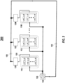
- FIG. 1 depicts a functional block diagram of a server rack serialized liquid cooling arrangement 100 , in accordance with the embodiments of the present disclosure.
- liquid cooling arrangement 100 includes a plurality of server clusters 110, 112 ... 11M that are fluidly connected in series to each other via a server rack liquid cooling loop 150 .
- the server rack liquid cooling loop 150 is configured to convey and facilitate the flow of a cooling liquid throughout the electronic equipment of the server rack and may be constructed from flexible materials (e.g., rubber, plastic, etc.), rigid materials (e.g., metal, PVC piping, etc.), or any combination of thereof.
- the conveyed liquid may include water, alcohol, or any suitable liquid capable of sustaining adequate cooling temperatures.
- Each of the server clusters 110, 112 ... 11M includes a plurality of server assemblies 110A-110N, 112A-112N ... 11MA-11MN that are arranged in a parallel manner.
- the server assemblies 110A-110N, 112A-112N ... 11MA-11MN contain heat generating electronic components.
- each of the parallel server assemblies 110A-110N, 112A-112N ... 11MA-11MN incorporates at least one respective liquid cooling unit 110A1-110N1, 112A1-112N1 ... 11MA1-11MN1, correspondingly arranged in parallel, for the direct thermal contact liquid cooling of the heat generating electronic components. That is, each of the liquid cooling units 110A1-110N1, 112A1-112N1 ... 11MA1-11MN1 is configured as liquid-cooled heat sink conduit block that is thermally coupled, either directly or indirectly, to the heat-generating electronic components, such that cooling liquid is circulated through internal liquid conduits of the liquid cooling units 110A1-110N1, 112A1-112N1 ... 11MA1-11MN1 to absorb the heat from the heat-generating electronic components and discharge the heated liquid therefrom.
- each one of the server clusters 110, 112 ... 11M may include a first manifold that, in use, receives the cooling liquid and feeds the cooling liquid to the plurality of liquid cooling units of the server cluster in parallel.
- a second manifold may be provided downstream said plurality of liquid cooling units to receive the cooling liquid from the plurality of liquid cooling units.
- the liquid cooling arrangement 100 further includes a plurality of air-to-liquid heat exchangers (ALHEXs) 120, 122 ... 12M for cooling the cooling liquid. More specifically, in an implementation, each of the air-to-liquid heat exchangers (ALHEXs) 120, 122 ... 12M defines an exchanger internal fluid conduit that forms a part of the cooling loop 150 . Therefore, each of the air-to-liquid heat exchangers (ALHEXs) 120, 122 ... 12M has an inlet through which, in use, the cooling liquid flows into the exchanger internal fluid conduit, and an outlet through which, in use, the cooling liquid is discharged from the exchanger internal fluid.
- AHEXs air-to-liquid heat exchangers
- the ALHEXs 120, 122 ... 12M of the liquid cooling arrangement 100 are fluidly connected in parallel with one another. Namely, the internal fluid conduits of the air-to-liquid heat exchangers (ALHEXs) 120, 122 ... 12M of the liquid cooling arrangement 100 are fluidly connected in parallel.
- the ALHEXs 120, 122 ... 12M of the liquid cooling arrangement 100 are also fluidly coupled to server clusters 110, 112 ... 11M via the liquid cooling loop 150 .
- the ALHEXs 120, 122 ... 12M function to sufficiently air cool the heated liquid received by the liquid cooling units 110A1-110N1, 112A1-112N1 ... 11MA1-11MN1 for redirection back to the server clusters 110, 112 ... 11M .
- the ALHEXs 120, 122 ... 12M may embody any suitable configuration that reduces liquid temperatures through supplied air flow, such as, internal cooling coils, heat extracting air flow fins, etc.
- the ALHEXs 120, 122 ... 12M may be, for example and without limitations, disposed on rear doors of a rack hosting the server clusters 110, 112 ... 11M .
- the liquid cooling arrangement 100 additionally includes at least one pump 130 that is fluidly connected to the server rack liquid cooling loop 150 .
- the pump 130 is configured to receive the cooling liquid from the ALHEXs 120, 122 ... 12M, via the server rack liquid cooling loop 150 , and functions to forcibly provide the necessary circulatory flow rate of the cooling liquid through the server rack liquid cooling loop 150 , in order to service the liquid cooling units 110A1-110N1, 112A1-112N1 ... 11MA1-11MN1 of server clusters 110, 112 ... 11M .
- Another parameter of interest are the "pinch" values of the ALHEXs 120, 122 ... 12M . That is, each of the ALHEXs 120, 122 ... 12M operate in a counter current configuration and thus has a "hot side" and a "cold side". So, for the hot side, the pinch value ⁇ T hotpinch is defined as the difference between the temperature of the hot liquid entering the ALHEX to be cooled by and the temperature of the hot air exiting the ALHEX. And, for the cold side, the pinch value ⁇ T coldpinch is defined as the difference between the temperature of the cooled liquid exiting the ALHEX and the temperature of cooled fresh air entering the ALHEX.
- pinch values ⁇ T hotpinch , ⁇ T coldpinch are positive numbers.
- a low pinch value ⁇ T coldpinch can benefit to the components to be cooled by the liquid cooling units 110A1-110N1, 112A1-112N1 ... 11MA1-11MN1.
- pinch value ⁇ T hotpinch may act as a "limiting pinch” that affects or conditions negatively a lower value of the ⁇ T coldpinch .
- the liquid cooling arrangement 100 employs a configuration that combines serialized and parallelized liquid cooled components to achieve efficient circulatory flow rates and maintain adequate liquid cooling temperatures.
- liquid cooled components arranged in series increase the fluid pressure drop in the liquid cooling loop 150 thereby inducing the pump 130 to operate at a lower flow rate.
- liquid cooled components arranged in parallel decrease the fluid pressure drop in the liquid cooling loop 150 thereby allowing the pump 130 to operate at a higher flow rate.
- the ALHEXs 120, 122 ... 12M may lose efficiency if their local liquid flow rate is reduced to a lower value.
- ⁇ T indicating the fluid temperature differences between the input and output sides of the serialized server clusters (see, Eq. 1), from the input of the first server cluster 110 to the output of the last server cluster 11M , as well as the pinch values ⁇ T hotpinch , ⁇ T coldpinch , and the temperature differences on the ALHEXs ⁇ T liquid , ⁇ T air , noted above.
- ⁇ T hotpinch is no longer limiting and the value of ⁇ T coldpinch is reduced along with the minimum temperature of the liquid cooling loop 150 .
- ⁇ T for the heating of the liquid in the cooling loop 150 is increased, as it represents the sum of each elevation of liquid temperatures of each server clusters 110 , 112 ... 11M.
- the cooling loop 150 alternates between transient thermal states and thermal steady state, where the cooling of the liquid in the cooling loop 150 (weighted-average of all the individual ⁇ T liquid ) is equalled to ⁇ T.
- liquid cooling arrangement 100 employs a configuration in which each of the serialized server clusters 110 , 112 ... 11M respectively incorporates multiple server assemblies 110A-110N , 112A-112N ... 11MA-11MN arranged in a parallel manner.
- the local circulatory flow rate to the liquid cooling units 110A1-110N1, 112A1-112N1 ... 11MA1-11MN1 is increased.
- the circulatory flow rate is the distributed global flow rate, which is reduced. As the circulatory flow rate in the ALHEXs is lower, the cold side pinch and the minimal temperature of the cooling liquid circulating within the liquid cooling loop 150 are reduced.
- the liquid cooling arrangement 100 provides for the pump 130 to convey the cooling liquid to the serially-coupled server clusters 110 , 112 ... 11M via an increased local circulatory flow rate.
- the cooling liquid is conveyed, in a parallel manner, at an increased local circulatory flow rate in the liquid cooling units 110A1-110N1 , 112A1-112N1 ... 11MA1-11MN1 of each of the server clusters 110 , 112 ... 11M.
- the cooling liquid As the cooling liquid successively flows through the server clusters 110 , 112 ... 11M , it collects at least a portion of the thermal energy generated by the corresponding electronic equipment of each server cluster. However, the temperature of the cooling liquid remains within tolerable levels sufficient to continue to cool the electronic equipment until the cooling liquid is outputted by the last server cluster 11M .
- the liquid outputted by the last server cluster 11M is subsequently forwarded to the parallelized ALHEX 120 , 122 ... 12M , at a reduced global circulatory flow rate, for cooling the cooling liquid prior to being redirected to the server cluster 110 by the liquid back to pump 130 .
- liquid cooling arrangement 100 provides a configuration that achieves a reduced global circulatory flow rate capable of efficiently cooling the electronic equipment contained within the server rack.
- liquid cooling arrangement 100 allows for the use of different piping conduit configurations as well as pumps that are capable of effectively handling the reduced global circulatory flow rate, resulting in reduced costs of materials, equipment, and volume of cooling liquid required.
- FIG. 2 depicts a functional block diagram of another server rack serialized liquid cooling arrangement 200 , in accordance with the embodiments of the present disclosure. Because the liquid cooling arrangement 200 contains similar components with like reference numerals as arrangement 100 , for the sake of brevity, detailed descriptions of such components will not be repeated unless necessary for the understanding of the embodiment.
- the liquid cooling arrangement 200 includes a plurality of server clusters 110, 112 ... 11M and a plurality of ALHEXs 120, 122 ... 12M that are fluidly connected in series to each other via the server rack liquid cooling loop 150 . That is, each of the server clusters 110, 112 ... 11M is serially coupled to a corresponding ALHEX 120, 122 ... 12M via server rack liquid cooling loop 150 .
- liquid cooling loop 150 conveys and facilitates the circulatory flow of cooling liquid throughout the electronic equipment of the server rack. More specifically, internal fluid conduits of the ALHEX 120, 122 ... 12M are fluidly connected in series with the server clusters 110, 112 ... 11M, the liquid cooling units of a same server cluster being fluidly connected in parallel.
- Each of the server clusters 110, 112 ... 11M includes a plurality of server assemblies 110A-110N, 112A-112N ... 11MA-11MN containing heat-generating electronic components, that are arranged in parallel fashion within the server clusters 110, 112 ... 11M .
- each of the server assemblies 110A-110N , 112A-112N ... 11MA-11MN incorporates at least one respective liquid cooling unit 110A1-110N1, 112A1-112N1 ... 11MA1-11MN1 for direct thermal contact liquid cooling of the heat-generating components, in which the respective liquid cooling unit 110A1-110N1, 112A1-112N1 ... 11MA1-11MN1 are accordingly arranged in a parallel manner.
- the ALHEXs 120, 122 ... 12M are configured to receive the heated cooling liquid from the liquid cooling units 110A1-110N1, 112A1-112N1 ... 11MA1-11MN1 of the respective server clusters 110, 112 ... 11M, via the server rack liquid cooling loop 150 .
- the ALHEXs 120, 122 ... 12M function to sufficiently air cool the heated liquid prior to forwarding the cooled cooling liquid to a succeeding server cluster 110, 112 ... 11M .
- the liquid cooling arrangement 200 additionally includes at least one pump 130 that is fluidly connected to the server rack liquid cooling loop 150 .
- the pump 130 conveys the cooling liquid in the cooling loop 150 , and thus causes the cooling liquid to flow from the last serially-coupled ALHEX 12M to the liquid cooling units 110A1-110N1, 112A1-112N1 ... 11MA1-11MN1 of server clusters 110, 112 ... 11M .
- liquid cooling arrangement 200 employs a configuration that combines serialized and parallelized components to achieve efficient circulatory flow rates and maintain adequate liquid cooling temperatures.
- the global circulatory flow rate of liquid cooling arrangement 200 is relatively reduced.
- the internal liquid cooling units 110A1-110N1, 112A1-112N1 ... 11MA1-11MN1 are organized in a parallel configuration.
- the global circulatory flow rate is relatively increased.
- the global circulatory flow rate is reduced.
- liquid cooling arrangement 200 provides for the pump 130 to convey the cooling liquid between the serially-coupled server clusters 110, 112 ... 11M and the ALHEXs 120, 122 ... 12M with local increased circulatory flow rates.
- the cooling liquid flows in the liquid cooling units 110A1-110N1, 112A1-112N1 ... 11MA1-11MN1 of each of the server clusters 110, 112 ... 11M at an increased local circulatory flow rate.
- the cooling liquid As the cooling liquid successively flows through the server clusters 110, 112 ... 11M, it collects at least a portion of the thermal energy generated by the corresponding electronic equipment of each server cluster. However, the cooling liquid is promptly cooled by a succeeding serially-coupled ALHEX 120, 122 ... 12M that, in turn, forwards the air-cooled liquid to a subsequent server cluster 110, 112 ... 11M . The air-cooled liquid outputted by the last ALHEX 12M is then directed back to pump 130 for recirculation at a reduced global circulatory flow rate.
- the liquid cooling arrangement 200 therefore provides a configuration in which, due to the serialization of liquid cooled components, the global circulatory flow rate is reduced while the local circulatory flow rate within the server clusters 110, 112 ... 11M, the internal liquid cooling units 110A1-110N1, 112A1-112N1 ... 11MA1-11MN1, and ALHEXs 120, 122 ... 12M is increased.
- liquid cooling arrangement 200 achieves a reduced global circulatory flow rate capable of efficiently cooling the electronic equipment contained within the server rack.
- liquid cooling arrangement 200 allows for the use of different piping conduit configurations as well as pumps that are capable of effectively handling the reduced global circulatory flow rate.
- FIG. 3 depicts a functional block diagram of another server rack liquid cooling arrangement 300 , in accordance with the embodiments of the present disclosure.
- the liquid cooling arrangement 300 includes a plurality of server clusters 110, 112 ... 11M that are each fluidly connected in series with a corresponding ALHEX 120, 122 ... 12M via the server rack liquid cooling loop 150 .
- the combination of each server cluster 110, 112 ... 11M serially coupled to a corresponding ALHEX 120, 122 ... 12M are then arranged in a parallel manner via the liquid cooling loop 150 .
- each of the server clusters 110, 112 ... 11M includes a plurality of server assemblies 110A-110N, 112A-112N ... 11MA-11MN incorporating at least one respective liquid cooling unit 110A1-110N1, 112A1-112N1 ... 11MA1-11MN1 that are fluidly connected in parallel with one another within the server clusters 110, 112 ... 11M .
- the ALHEXs 120, 122 ... 12M are configured to receive the heated cooling liquid from the liquid cooling units 110A1-110N1, 112A1-112N1 ... 11MA1-11MN1 of the respective server clusters 110, 112 ... 11M, via the liquid cooling loop 150 .
- the ALHEXs 120, 122 ... 12M function to sufficiently air cool the heated liquid prior to forwarding the cooled cooling liquid to a succeeding server cluster 110, 112 ... 11M .
- the liquid cooling arrangement 300 additionally includes at least one pump 130 that is fluidly connected to the server rack liquid cooling loop 150 .
- the pump 130 conveys the cooling liquid from the parallelized ALHEXs 120, 122 ... 12M, via the server rack liquid cooling loop 150, and functions to forcibly provide the necessary circulatory flow rate of the cooling liquid through the server rack liquid cooling loop 150, in order to service the liquid cooling units 110A1-110N1, 112A1-112N1 ... 11MA1-11MN1 of server clusters 110, 112 ... 11M .
- the liquid cooling arrangement 300 therefore provides a configuration in which the global circulatory flow rate is relatively reduced due to the serial connection of the server clusters 110, 112 ... 11M with corresponding ALHEX 120, 122 ... 12M .
- the global circulatory flow rate is increased.
- the local circulatory flow rate within the server clusters 110, 112 ... 11M and internal liquid cooling units 110A1-110N1, 112A1-112N1 ... 11MA1-11MN1 is reduced.
- liquid cooling arrangement 300 achieves an increased global circulatory flow rate capable of efficiently cooling the electronic equipment contained within the server rack.
- liquid cooling arrangement 300 allows for the use of different piping conduit configurations as well as pumps that are capable of effectively handling the increased global circulatory flow rate.
- FIG. 4 depicts a functional block diagram of another server rack liquid cooling arrangement 400 , in accordance with the embodiments of the present disclosure.
- the liquid cooling arrangement 400 includes a plurality of server clusters 110, 112 ... 11M that are each fluidly connected in series with a corresponding ALHEX 120, 122 ... 12M via the liquid cooling loop 150 .
- the combination of each server cluster 110, 112 ... 11M serially coupled to a corresponding ALHEX 120, 122 ... 12M are then arranged in a fluidly coupled parallel manner via the liquid cooling loop 150 .
- Each of the server clusters 110, 112 ... 11M includes a plurality of server assemblies 110A-110N, 112A-112N ... 11MA-11MN that are arranged in serial fashion within the server clusters 110, 112 ... 11M .
- each of the server assemblies 110A-110N , 112A-112N ... 11MA-11MN incorporates at least one respective liquid cooling unit 110A1-110N1, 112A1-112N1 ... 11MA1-11MN1 for direct thermal contact liquid cooling that are accordingly arranged in a serial manner. That is, in each server cluster 110, 112 ... 11M, the cooling liquid is supplied to a liquid cooling unit 110A1-110N1, 112A1-112N1 ...
- the server assemblies 110A-110N, 112A-112N ... 11MA-11MN that are arranged in series may comprise groups of server assemblies that are fluidly connected in a parallel manner.
- the parallel ALHEXs 120, 122 ... 12M are configured to receive the heated liquid from the liquid cooling units 110A1-110N1, 112A1-112N1 ... 11MA1-11MN1 of the respective serially-coupled server clusters 110, 112 ... 11M, via the server rack liquid cooling loop 150.
- the ALHEXs 120, 122 ... 12M function to sufficiently air cool the heated cooling liquid prior to forwarding the cooled liquid to the succeeding server clusters 110, 112 ... 11M.
- the liquid cooling arrangement 400 additionally includes at least one pump 130 that is fluidly connected to the server rack liquid cooling loop 150 .
- the pump 130 is configured to receive the cooling liquid from the parallelized ALHEXs 120, 122 ... 12M, via the server rack liquid cooling loop 150 , and functions to forcibly provide the necessary circulatory flow rate of the air-cooled liquid through the server rack liquid cooling loop 150 in a parallel manner, in order to service the liquid cooling units 110A1-110N1, 112A1-112N1 ... 11MA1-11MN1 of server clusters 110, 112 ... 11M .
- liquid cooling arrangement 400 provides for pump 130 to supply air-cooled liquid to the parallelized combination of server clusters 110, 112 ... 11M and serially-coupled ALHEXs 120, 122 ... 12M via a reduced global circulatory flow rate.
- each of the server clusters 110, 112 ... 11M supply air-cooled liquid to the serialized liquid cooling units 110A1-110N1, 112A1-112N1 ... 11MA1-11MN1 at an increased local circulatory flow rate.
- the liquid cooling arrangement 400 therefore provides a configuration in which the global circulatory flow rate is reduced due to the serial connection of the server clusters 110, 112 ... 11M with corresponding ALHEX 120, 122 ... 12M and the local circulatory flow rate within the server clusters 110, 112 ... 11M is reduced while the local circulatory flow rate of the internal liquid cooling units 110A1-110N1, 112A1-112N1 ... 11MA1-11MN1 is increased. Additionally, the local circulatory flow rate within the ALHEXs is also reduced.
- liquid cooling arrangement 400 provides a configuration that achieves a reduced global circulatory flow rate capable of efficiently cooling the electronic equipment contained within the server rack. As such, liquid cooling arrangement 400
Landscapes
- Engineering & Computer Science (AREA)
- Microelectronics & Electronic Packaging (AREA)
- Physics & Mathematics (AREA)
- Thermal Sciences (AREA)
- Computer Hardware Design (AREA)
- General Engineering & Computer Science (AREA)
- Cooling Or The Like Of Electrical Apparatus (AREA)
Priority Applications (3)
| Application Number | Priority Date | Filing Date | Title |
|---|---|---|---|
| EP23305473.3A EP4440271A1 (de) | 2023-03-31 | 2023-03-31 | Serialisierte flüssigkeitskühlungsanordnungen für datencenterserverracks |
| US18/617,792 US20240334648A1 (en) | 2023-03-31 | 2024-03-27 | Serialized liquid cooling arrangements for datacenter server racks |
| CN202410375192.8A CN118741947A (zh) | 2023-03-31 | 2024-03-29 | 用于数据中心服务器机架的串联液体冷却装置 |
Applications Claiming Priority (1)
| Application Number | Priority Date | Filing Date | Title |
|---|---|---|---|
| EP23305473.3A EP4440271A1 (de) | 2023-03-31 | 2023-03-31 | Serialisierte flüssigkeitskühlungsanordnungen für datencenterserverracks |
Publications (1)
| Publication Number | Publication Date |
|---|---|
| EP4440271A1 true EP4440271A1 (de) | 2024-10-02 |
Family
ID=86226427
Family Applications (1)
| Application Number | Title | Priority Date | Filing Date |
|---|---|---|---|
| EP23305473.3A Pending EP4440271A1 (de) | 2023-03-31 | 2023-03-31 | Serialisierte flüssigkeitskühlungsanordnungen für datencenterserverracks |
Country Status (3)
| Country | Link |
|---|---|
| US (1) | US20240334648A1 (de) |
| EP (1) | EP4440271A1 (de) |
| CN (1) | CN118741947A (de) |
Families Citing this family (2)
| Publication number | Priority date | Publication date | Assignee | Title |
|---|---|---|---|---|
| CN115297681A (zh) * | 2022-08-03 | 2022-11-04 | 台达电子企业管理(上海)有限公司 | 车载功率装置与热管理系统 |
| EP4152906A1 (de) * | 2022-08-25 | 2023-03-22 | Ovh | Kühlanordnung und verfahren zum kühlen von mehreren wärmeerzeugenden komponenten |
Citations (3)
| Publication number | Priority date | Publication date | Assignee | Title |
|---|---|---|---|---|
| US20200253090A1 (en) * | 2019-02-01 | 2020-08-06 | Taiwan Microloops Corp. | Water-cooled pressurized distributive heat dissipation system for rack |
| EP4142443A1 (de) * | 2021-08-30 | 2023-03-01 | Ovh | Rack-anordnung für eine datenzentrale und verfahren zur steuerung der kühlflüssigkeit in einer kühlschleife der rack-anordnung |
| EP4152906A1 (de) * | 2022-08-25 | 2023-03-22 | Ovh | Kühlanordnung und verfahren zum kühlen von mehreren wärmeerzeugenden komponenten |
-
2023
- 2023-03-31 EP EP23305473.3A patent/EP4440271A1/de active Pending
-
2024
- 2024-03-27 US US18/617,792 patent/US20240334648A1/en active Pending
- 2024-03-29 CN CN202410375192.8A patent/CN118741947A/zh active Pending
Patent Citations (3)
| Publication number | Priority date | Publication date | Assignee | Title |
|---|---|---|---|---|
| US20200253090A1 (en) * | 2019-02-01 | 2020-08-06 | Taiwan Microloops Corp. | Water-cooled pressurized distributive heat dissipation system for rack |
| EP4142443A1 (de) * | 2021-08-30 | 2023-03-01 | Ovh | Rack-anordnung für eine datenzentrale und verfahren zur steuerung der kühlflüssigkeit in einer kühlschleife der rack-anordnung |
| EP4152906A1 (de) * | 2022-08-25 | 2023-03-22 | Ovh | Kühlanordnung und verfahren zum kühlen von mehreren wärmeerzeugenden komponenten |
Also Published As
| Publication number | Publication date |
|---|---|
| US20240334648A1 (en) | 2024-10-03 |
| CN118741947A (zh) | 2024-10-01 |
Similar Documents
| Publication | Publication Date | Title |
|---|---|---|
| US11006547B2 (en) | Solution for precision cooling and fluid management optimization in immersion cooling | |
| US20240334648A1 (en) | Serialized liquid cooling arrangements for datacenter server racks | |
| US7907406B1 (en) | System and method for standby mode cooling of a liquid-cooled electronics rack | |
| KR102126615B1 (ko) | 데이터 센터의 전자 랙의 복합형 액체 공기 냉각 시스템에 대한 최적의 제어 장치 | |
| US11096315B2 (en) | Multifunction coolant manifold structures | |
| US8514575B2 (en) | Multimodal cooling apparatus for an electronic system | |
| US10225958B1 (en) | Liquid cooling system for a data center | |
| US10595447B2 (en) | Effectiveness-weighted control of cooling system components | |
| US11924998B2 (en) | Hybrid immersion cooling system for rack-mounted electronic assemblies | |
| US8879257B2 (en) | Combined power and cooling rack supporting an electronics rack(s) | |
| US8583290B2 (en) | Cooling system and method minimizing power consumption in cooling liquid-cooled electronics racks | |
| US7757506B2 (en) | System and method for facilitating cooling of a liquid-cooled electronics rack | |
| EP2786647B1 (de) | Kühlsystem für einen server | |
| US20250212370A1 (en) | Prioritized liquid cooling arrangements for datacenter server racks | |
| US20140085817A1 (en) | Immersion-cooling of selected electronic component(s) mounted to printed circuit board | |
| EP3654744B1 (de) | Verfahren zur kühlung eines elektronikschranks | |
| US11991866B2 (en) | Adaptive cascade cooling method for datacenters | |
| US12598721B2 (en) | Cooling assembly and method for cooling a plurality of heat-generating components | |
| US20100275618A1 (en) | System and method for cooling fluid distribution | |
| CN112186289A (zh) | 备用电池模块和包括备用电池模块的备用电池组件 | |
| CN115279114A (zh) | 用于冷却服务器机架的流体回路和系统 | |
| US20190128271A1 (en) | Pump with integrated bypass mechanism | |
| US10897837B1 (en) | Cooling arrangement for a server mountable in a server rack | |
| EP4142444B1 (de) | Verfahren zur steuerung eines kühlsystems zur autonomen kühlung eines racks | |
| US20250341874A1 (en) | Liquid-assisted and thermoelectric-based temperature control for servers and other electronic equipment |
Legal Events
| Date | Code | Title | Description |
|---|---|---|---|
| PUAI | Public reference made under article 153(3) epc to a published international application that has entered the european phase |
Free format text: ORIGINAL CODE: 0009012 |
|
| STAA | Information on the status of an ep patent application or granted ep patent |
Free format text: STATUS: REQUEST FOR EXAMINATION WAS MADE |
|
| 17P | Request for examination filed |
Effective date: 20240122 |
|
| AK | Designated contracting states |
Kind code of ref document: A1 Designated state(s): AL AT BE BG CH CY CZ DE DK EE ES FI FR GB GR HR HU IE IS IT LI LT LU LV MC ME MK MT NL NO PL PT RO RS SE SI SK SM TR |