EP4440102A1 - Systeme und verfahren für ein kartenbasiertes mehrkamera-ansichts-dashboard - Google Patents
Systeme und verfahren für ein kartenbasiertes mehrkamera-ansichts-dashboard Download PDFInfo
- Publication number
- EP4440102A1 EP4440102A1 EP24168154.3A EP24168154A EP4440102A1 EP 4440102 A1 EP4440102 A1 EP 4440102A1 EP 24168154 A EP24168154 A EP 24168154A EP 4440102 A1 EP4440102 A1 EP 4440102A1
- Authority
- EP
- European Patent Office
- Prior art keywords
- camera
- user interface
- graphical user
- environment
- window
- Prior art date
- Legal status (The legal status is an assumption and is not a legal conclusion. Google has not performed a legal analysis and makes no representation as to the accuracy of the status listed.)
- Granted
Links
Images




Classifications
-
- H—ELECTRICITY
- H04—ELECTRIC COMMUNICATION TECHNIQUE
- H04N—PICTORIAL COMMUNICATION, e.g. TELEVISION
- H04N7/00—Television systems
- H04N7/18—Closed-circuit television [CCTV] systems, i.e. systems in which the video signal is not broadcast
- H04N7/181—Closed-circuit television [CCTV] systems, i.e. systems in which the video signal is not broadcast for receiving images from a plurality of remote sources
-
- G—PHYSICS
- G08—SIGNALLING
- G08B—SIGNALLING SYSTEMS, e.g. PERSONAL CALLING SYSTEMS; ORDER TELEGRAPHS; ALARM SYSTEMS
- G08B13/00—Burglar, theft or intruder alarms
- G08B13/18—Actuation by interference with heat, light, or radiation of shorter wavelength; Actuation by intruding sources of heat, light, or radiation of shorter wavelength
- G08B13/189—Actuation by interference with heat, light, or radiation of shorter wavelength; Actuation by intruding sources of heat, light, or radiation of shorter wavelength using passive radiation detection systems
- G08B13/194—Actuation by interference with heat, light, or radiation of shorter wavelength; Actuation by intruding sources of heat, light, or radiation of shorter wavelength using passive radiation detection systems using image scanning and comparing systems
- G08B13/196—Actuation by interference with heat, light, or radiation of shorter wavelength; Actuation by intruding sources of heat, light, or radiation of shorter wavelength using passive radiation detection systems using image scanning and comparing systems using television cameras
- G08B13/19678—User interface
- G08B13/19691—Signalling events for better perception by user, e.g. indicating alarms by making display brighter, adding text, creating a sound
- G08B13/19693—Signalling events for better perception by user, e.g. indicating alarms by making display brighter, adding text, creating a sound using multiple video sources viewed on a single or compound screen
-
- G—PHYSICS
- G08—SIGNALLING
- G08B—SIGNALLING SYSTEMS, e.g. PERSONAL CALLING SYSTEMS; ORDER TELEGRAPHS; ALARM SYSTEMS
- G08B13/00—Burglar, theft or intruder alarms
- G08B13/18—Actuation by interference with heat, light, or radiation of shorter wavelength; Actuation by intruding sources of heat, light, or radiation of shorter wavelength
- G08B13/189—Actuation by interference with heat, light, or radiation of shorter wavelength; Actuation by intruding sources of heat, light, or radiation of shorter wavelength using passive radiation detection systems
- G08B13/194—Actuation by interference with heat, light, or radiation of shorter wavelength; Actuation by intruding sources of heat, light, or radiation of shorter wavelength using passive radiation detection systems using image scanning and comparing systems
- G08B13/196—Actuation by interference with heat, light, or radiation of shorter wavelength; Actuation by intruding sources of heat, light, or radiation of shorter wavelength using passive radiation detection systems using image scanning and comparing systems using television cameras
- G08B13/19639—Details of the system layout
- G08B13/19645—Multiple cameras, each having view on one of a plurality of scenes, e.g. multiple cameras for multi-room surveillance or for tracking an object by view hand-over
-
- G—PHYSICS
- G08—SIGNALLING
- G08B—SIGNALLING SYSTEMS, e.g. PERSONAL CALLING SYSTEMS; ORDER TELEGRAPHS; ALARM SYSTEMS
- G08B13/00—Burglar, theft or intruder alarms
- G08B13/18—Actuation by interference with heat, light, or radiation of shorter wavelength; Actuation by intruding sources of heat, light, or radiation of shorter wavelength
- G08B13/189—Actuation by interference with heat, light, or radiation of shorter wavelength; Actuation by intruding sources of heat, light, or radiation of shorter wavelength using passive radiation detection systems
- G08B13/194—Actuation by interference with heat, light, or radiation of shorter wavelength; Actuation by intruding sources of heat, light, or radiation of shorter wavelength using passive radiation detection systems using image scanning and comparing systems
- G08B13/196—Actuation by interference with heat, light, or radiation of shorter wavelength; Actuation by intruding sources of heat, light, or radiation of shorter wavelength using passive radiation detection systems using image scanning and comparing systems using television cameras
- G08B13/19678—User interface
- G08B13/19682—Graphic User Interface [GUI] presenting system data to the user, e.g. information on a screen helping a user interacting with an alarm system
-
- G—PHYSICS
- G08—SIGNALLING
- G08B—SIGNALLING SYSTEMS, e.g. PERSONAL CALLING SYSTEMS; ORDER TELEGRAPHS; ALARM SYSTEMS
- G08B13/00—Burglar, theft or intruder alarms
- G08B13/18—Actuation by interference with heat, light, or radiation of shorter wavelength; Actuation by intruding sources of heat, light, or radiation of shorter wavelength
- G08B13/189—Actuation by interference with heat, light, or radiation of shorter wavelength; Actuation by intruding sources of heat, light, or radiation of shorter wavelength using passive radiation detection systems
- G08B13/194—Actuation by interference with heat, light, or radiation of shorter wavelength; Actuation by intruding sources of heat, light, or radiation of shorter wavelength using passive radiation detection systems using image scanning and comparing systems
- G08B13/196—Actuation by interference with heat, light, or radiation of shorter wavelength; Actuation by intruding sources of heat, light, or radiation of shorter wavelength using passive radiation detection systems using image scanning and comparing systems using television cameras
- G08B13/19678—User interface
- G08B13/19691—Signalling events for better perception by user, e.g. indicating alarms by making display brighter, adding text, creating a sound
Definitions
- the described aspects relate to security camera systems, and more particularly, to a map-based multi-camera dashboard.
- An example aspect includes a method for controlling a multi-camera view user interface, comprising generating, for a graphical user interface, a respective camera window for each respective camera of the plurality of cameras in different areas of an environment, wherein the respective camera window outputs a stream captured by the respective camera.
- the method further includes arranging the graphical user interface according to a camera window placement scheme based on a layout of the environment, wherein arranging the graphical user interface comprises assigning a first camera window of a first camera of the plurality of cameras a position on the graphical user interface relative to other generated camera windows based on a physical position of an area in the environment associated with the first camera relative to other areas in the environment.
- the method further includes generating, for display, a dashboard comprising the graphical user interface organized according to the camera window placement scheme.
- Another example aspect includes an apparatus for controlling a multi-camera view user interface, comprising a memory and a processor coupled with the memory.
- the processor is configured to generate, for a graphical user interface, a respective camera window for each respective camera of the plurality of cameras in different areas of an environment, wherein the respective camera window outputs a stream captured by the respective camera.
- the processor is further configured to arrange the graphical user interface according to a camera window placement scheme based on a layout of the environment, wherein arranging the graphical user interface comprises assigning a first camera window of a first camera of the plurality of cameras a position on the graphical user interface relative to other generated camera windows based on a physical position of an area in the environment associated with the first camera relative to other areas in the environment.
- the processor further configured to generate, for display, a dashboard comprising the graphical user interface organized according to the camera window placement scheme.
- Another example aspect includes an apparatus for controlling a multi-camera view user interface, comprising means for generating, for a graphical user interface, a respective camera window for each respective camera of the plurality of cameras in different areas of an environment, wherein the respective camera window outputs a stream captured by the respective camera.
- the apparatus further includes means for arranging the graphical user interface according to a camera window placement scheme based on a layout of the environment, wherein arranging the graphical user interface comprises assigning a first camera window of a first camera of the plurality of cameras a position on the graphical user interface relative to other generated camera windows based on a physical position of an area in the environment associated with the first camera relative to other areas in the environment.
- the apparatus further includes means for generating, for display, a dashboard comprising the graphical user interface organized according to the camera window placement scheme.
- Another example aspect includes a computer-readable medium having instructions stored thereon for controlling a multi-camera view user interface, wherein the instructions are executable by a processor to generate, for a graphical user interface, a respective camera window for each respective camera of the plurality of cameras in different areas of an environment, wherein the respective camera window outputs a stream captured by the respective camera.
- the instructions are further executable to arrange the graphical user interface according to a camera window placement scheme based on a layout of the environment, wherein arranging the graphical user interface comprises assigning a first camera window of a first camera of the plurality of cameras a position on the graphical user interface relative to other generated camera windows based on a physical position of an area in the environment associated with the first camera relative to other areas in the environment.
- the instructions are further executable to generate, for display, a dashboard comprising the graphical user interface organized according to the camera window placement scheme.
- the one or more aspects comprise the features hereinafter fully described and particularly pointed out in the claims.
- the following description and the annexed drawings set forth in detail certain illustrative features of the one or more aspects. These features are indicative, however, of but a few of the various ways in which the principles of various aspects may be employed, and this description is intended to include all such aspects and their equivalents.
- the present disclosure includes apparatuses and methods for generating and controlling a map-based multi-camera dashboard. More specifically, the multi-camera dashboard described herein is operative to position and size camera windows based on where the cameras are installed and their field of view, respectfully. Camera windows may additionally show other security information such as the amount of people in a given area of an environment, whether the doors of the area are open/closed/locked, the devices in the area, etc. Because the camera windows are relatively positioned on dashboard user interface based on their real-life positions, security personnel can immediately determine where security events are happening. Furthermore, in one or more aspects, as security events begin accumulating in certain areas, a visual indicator of such increased activity, such as but not limited to a heat map, is generated on the dashboard to improve identification of the areas with the most need for attention.
- a visual indicator of such increased activity such as but not limited to a heat map
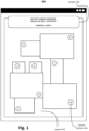
- Fig. 1 is a diagram 100 of an example of a user interface requesting a layout for use in a map-based multi-camera dashboard.
- the user interface is generated by a user interface component (described in FIG. 7 ).
- the user interface requests an environment layout.
- the user may draw layout 102 on the user interface or upload an image, graphic, or any other data representing the layout 102 (e.g., of a floorplan).
- the user may then mark the locations of cameras, which may also be referred to as or be associated with a camera placement scheme, in layout 102.
- a camera placement scheme refers to a relative location of a plurality of camera within the layout 102, where the relative location may be defined by areas in the layout 102, geographic location information, and/or any other data suitable to indicate a relative position of each camera.
- camera position 104 is the position of a camera identified as camera number "8.”
- marking a location is performed by selecting an area in the layout.
- the user interface component may generate a marker in the selected area.
- the marker is a visual icon that may include and/or otherwise represent or indicate a camera identifier.
- the camera identifier may any combination of characters that are unique to the camera (e.g., a number, a letter, a name, a MAC address, or any combination thereof, etc.).
- the camera identifier is a number between 1 and 9.
- a camera with the identifier "8" has a marker of a circle with the number 8 inside.
- the user interface may include header 106, which provides information such as time, location, and provides options such as "camera settings," "view editor,” etc. Header 106 may also include information about what the user is looking at. For example, in FIG. 1 , header 106 indicates that a layout is being generated.
- Fig. 2 is a diagram 200 of an example of a user interface displaying a plurality of camera views simultaneously in accordance with a camera placement scheme and a layout 102.
- Layout 102 may be a floorplan of the first floor.
- the user interface component may generate a layout for each floor simultaneously, but for simplicity, suppose that only one floor is shown in FIGS. 1-6 .
- the user interface component may receive a video feed from each camera in the environment associated with the layout 102 and generate respective camera windows 201 on the user interface to display the respective video feeds.
- the camera windows are not simply arranged in a generic grid-like manner. Instead, the user interface component arranges the user interface according to a camera window placement scheme based on a layout of the environment. More specifically, the user interface component assigns a respective camera window of each camera a position on the user interface relative to other generated camera windows based on a physical position of an area in the environment associated with each camera relative to other areas in the environment. For example, FIG.
- each of the plurality of camera windows is based on camera placement scheme, e.g., based on at least a location of each respective area. For example, and additionally referring to Fig. 1 , the location of the area associated with camera 2 is below the location of the area associated with camera 4 (and to the left of the area associated with camera 8). Consequently, the user interface component arranges the user interface such that the camera window 204 associated with camera 2 is displayed, in the layout 102, below the camera window 206 associated with camera 4 (and to the left of the respective camera window associated with camera 8).
- the camera windows 201 are arranged such that each respective camera window is in a same relative position as the corresponding area in the layout 102.
- a size of each of the camera windows may be additionally based on a size of the area within which a respective camera is located.
- the area where camera 2 is installed is a room
- the visual size of camera window 204 is proportional to the physical size of said room relative to the sizes of other areas in the layout 102.
- Fig. 3 is a diagram 300 of an example of a user interface displaying a plurality of camera views simultaneously in accordance with another camera placement scheme.
- the user interface component arranges each of the camera windows and sizes them based on a size of the area captured by the camera.
- the arrangement of the cameras is a dynamic grid where each camera window is still positioned based on the location of the camera in the environment relative to one another, albeit in a collapsed manner so that the space between each camera window is even.
- the size of the area captured by the camera is estimated based on the size of an object captured within the frame.
- the object may be a person.
- the user interface may resize each camera window such that the size of a detected person is within a threshold size window.
- the threshold size window may be 15 - 40 pixels.
- the camera window will be larger as compared to camera windows for cameras that capture small spaces such as a single office room.
- the plurality of camera windows are sized such that all persons are within the threshold size window. Accordingly, each person is at least 15 pixels tall and at most 40 pixels tall.
- the user interface component arranges the conference room view (an oval with 14 persons) to have a larger camera window compared to, for example, camera window 302 featuring camera view 202 or the other camera windows where the cameras are physically located closer to persons.
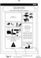
- Fig. 4 is a diagram 400 of an example of a user interface displaying a plurality of camera views and security information simultaneously in accordance with a camera placement scheme.
- the user interface component generates security information within the camera windows.
- camera window 302 includes security information 402 within camera view 202.
- the security information 402 may replace the actual feed as shown in camera window 302 or may be overlaid on the feed as shown in camera window 404.
- This security information indicates that there are four occupants in the area, and an animal has been detected. Additional security information includes whether the doors are locked/unlocked, and device information in the area such as the temperature setting of a thermostat. The security information may also indicate the amount of security events that have occurred within a threshold time period (e.g., past hour, past day, etc.) and the list of occupants. For example, the occupants of the conference room are listed by initials in FIG. 4 . A user may select the security information to gather more information about security events. For example, a user may select (e.g., by clicking or touching) an icon with the initials of an occupant to determine their full name, job title, etc.
- a threshold time period e.g., past hour, past day, etc.
- the user interface component may automatically alert the user in the corresponding camera window.
- camera window 302 originally showed camera view 202 (see Fig. 3 ).
- the user interface component displays security information 402 in camera window 302.
- a security event may be any predetermined attribute or occurrence associated with the environment that a user would like to gain information about. Examples of security events include fire detection, water detection, unauthorized access detection, forced door opening, detection of physical violence, theft detection, etc.
- there may be one or more security sensors in a monitored environment that are operative to detect and generate such security events e.g., a carbon monoxide detector may detect fires or smoke).
- Fig. 5 is a diagram 500 of an example of a user interface displaying a high activity indication, such as but not limited to a heat map, based on security information in accordance with a camera placement scheme.
- the camera placement scheme is the same as the scheme shown in FIG. 2 .
- the additional feature depicted in diagram 500 is the inclusion of a high activity indication, referred to as a heat map indicator 502.
- the user interface component may track the amount of security events that have happened in a given area. In response to determining that the amount of security events is greater than a threshold amount, the user interface component may generate heat map indicator 502 to visually alert the user of increased security event activity in a given area.
- Heat map indicator 502 is a visual cue (e.g., a change in color of the window, a resized window, an increase in resolution of the view, etc.) that makes the camera view and/or security information for a particular area stand out in comparison to other camera views and/or security information on the user interface.
- the heat map indicator 502 is shading or color applied to the camera window, and in this case the heat map indicator 502 additionally includes security event information, such as words or a code that may be associated with the security event (e.g., "Security Event A: 3" in this case, providing a count (e.g., "3") of the number of security events of type "A" that have occurred in the area).
- the security event information may be overlaid on a feed or may replace the feed.
- Fig. 6 is a diagram of an example of two user interfaces 600 and 602 respectively displaying security information and a heat map in accordance with a camera placement scheme.
- User interface 600 presents camera windows such as camera window 606 and security information such as security information 604 in a mobile view.
- the environment in which the cameras are installed is a university campus with multiple buildings.
- User interface 600 depicts one type of view that includes the camera windows arranged according to a camera window placement scheme.
- User interface 602 depicts a different type of view in which a three-dimensional visual representation of the campus buildings is shown.
- This three-dimensional visual representation is another format in which the layout of an environment may be generated.
- layout 102 in FIG. 1 represents a two-dimensional visual representation of the rooms in one building.
- arranging the graphical user interface according to the camera window placement scheme is spatially variable relative to a user device in the environment presenting the dashboard based on location information and direction information associated with the user device.
- the computing device may use a combination of a global positioning system (GPS), inertial measurement unit (IMU), and computer vision to determine location and orientation. For example, based on an image captured in the direction that the camera is facing, localization techniques may be executed by user interface component to determine the direction.
- GPS global positioning system
- IMU inertial measurement unit
- the arrangement of the camera windows may change based on the position and the direction the computing device (e.g., the smartphone the user is accessing user interface 600 on) is facing.
- the computing device e.g., the smartphone the user is accessing user interface 600 on
- the camera window include security information 604 may be situated above camera window 606 (as shown in user interface 600).
- the user interface component may rotate the camera windows relative to camera window 606 by 180 degrees. This would place the camera window including security information 604 to be below camera window 606 on the user interface.
- the user interface component may rotate the camera windows about the camera window of the area that the user is currently in.
- computing device 700 may perform a method 800 for controlling a multi-camera view user interface, by such as via execution of user interface component 715 by processor 705 and/or memory 710.
- the method 800 includes generating, for a graphical user interface, a respective camera window for each respective camera of the plurality of cameras in different areas of an environment, wherein the respective camera window outputs a stream captured by the respective camera.
- computing device 700, processor 705, memory 710, user interface component 715, and/or generating component 720 may be configured to or may comprise means for generating, for a graphical user interface, a respective camera window (e.g., camera window 204) for each respective camera of the plurality of cameras in different areas of an environment, wherein the respective camera window outputs a stream (e.g., camera view 202) captured by the respective camera.
- computing device 700, processor 705, memory 710, user interface component 715, and/or arranging component 725 may be configured to or may comprise means for arranging the graphical user interface according to a camera window placement scheme based on a layout of the environment, wherein arranging the graphical user interface comprises assigning a first camera window of a first camera of the plurality of cameras a position on the graphical user interface relative to other generated camera windows based on a physical position of an area in the environment associated with the first camera relative to other areas in the environment.
- user interface component 715 may receive layout 102 of the environment and identify the locations of each camera (e.g., camera position 104). In some aspects, user interface component 715 may identify each area in layout 102. For example, an area may be a room, a hall, a foyer, etc. User interface component 715 may then create at least one camera window for each area depending on the amount of cameras within the area. Referring to FIG. 1 , for example, camera 2 is located in a room of a given width and length in a given location relative to the other areas in layout 2. User interface component 715 generates camera window 204 for camera 2 and sets the size of the window proportionally based on the given width and length. In addition, the location of the camera window is assigned based on the given location of the room. User interface component 715 arranges the other camera windows in the same manner.
- the end result is the user interface shown in FIG. 2 , where the camera windows are sized and arranged to match layout 102.
- the user interface component 715 adjusts the resolution and aspect ratio of the video streams to fit within the camera window that houses the video stream. In some aspects, user interface component 715 adjusts the resolution and aspect ratio of the video streams such that they fill their corresponding camera windows.
- the end result of the arrangement is the user interface shown in FIG. 3 , where the space between the camera windows is equal, the size of the camera windows is based on the area captured by a camera, and the location of the camera window relative to the other camera windows is based on the location of the physical camera location relative to the other physical camera locations.
- the arranging at block 804 of the graphical user interface according to the camera window placement scheme further includes setting a window size of the first camera window based on an area size of the area associated with the first camera.
- the first area may be 15 feet by 15 feet in physical length and width.
- the second area may be 30 feet by 15 feet.
- user interface component 715 may generate a first camera window that is 150 pixels by 150 pixels and a second camera window that is 300 pixels by 150 pixels for the first area and the second area, respectively.
- a respective window size and a respective window position of each respective camera window is proportional to a respective area size and a respective area position of each area in the environment corresponding to each of the plurality of cameras.
- the first area may be adjacent to the second area such that together their form a rectangle that is 45 feet by 15 feet.
- user interface component 715 may place the first camera window adjacent to the second camera window such that the together they form a rectangle that is 450 pixels by 150 pixels.
- the arranging at block 804 of the graphical user interface according to the camera window placement scheme further includes setting a window size of each camera window based on an object size of an object captured by the plurality of cameras such that the object size of the object is equal across each respective camera window of the graphical user interface.
- an object may be a person.
- the size of the object in a first camera window is 20 pixels in length. If a person appears in the second camera window, the user interface component may resize the second camera window to ensure that the size of the object in the second camera window is also 20 pixels in length. Because some objects are positioned farther away from a camera and appear smaller as a result, this allows for the object of interest that is being monitored to be the same throughout the user interface. For example, in FIG. 3 , all of the camera windows are sized such that people are with the same threshold size. Thus, the view of the conference room with fourteen occupants is much larger than the view of a singular office focused on one person.
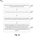
- the method 800 may further include receiving notification of a security event that is detected in at least one area of the environment.
- computing device 700, processor 705, memory 710, user interface component 715, and/or receiving component 730 may be configured to or may comprise means for receiving notification of a security event that is detected in at least one area of the environment.
- the security event may indicate that an animal has entered the environment.
- the method 800 may further include generating a security event alert in the dashboard.
- computing device 700, processor 705, memory 710, user interface component 715, and/or generating component 720 may be configured to or may comprise means for generating a security event alert in the dashboard.
- an alert is generated in camera window 302 indicating that the animal is detected.
- generating the graphical user interface further comprises generating security event information in at least one respective camera window, the security information associated with a respective area in the environment associated with the respective camera window.
- the security event information comprises, for a given area, one or any combination of: an occupancy count, an occupancy indicator, a security personnel indicator, a security alert indicator, a security event history, a device count, or a device status list.
- the method 800 may further include receiving notification of a security event that is detected in the area associated with the first camera.
- computing device 700, processor 705, memory 710, user interface component 715, and/or receiving component 730 may be configured to or may comprise means for receiving notification of a security event that is detected in the area associated with the first camera.
- the method 800 may further include generating a security event alert in the first camera window.
- computing device 700, processor 705, memory 710, user interface component 715, and/or generating component 720 may be configured to or may comprise means for generating a security event alert in the first camera window (e.g., as shown in camera window 302).
- the method 800 may further include determining that a security event count in the area associated with the first camera exceeds a threshold security event count.
- computing device 700, processor 705, memory 710, user interface component 715, and/or determining component 735 may be configured to or may comprise means for determining that a security event count (e.g., 3) in the area associated with the first camera exceeds a threshold security event count (e.g., 2) during a given period of time (e.g., 1 hour).
- the method 800 may further include adjusting an appearance of the first camera window in a heat map view of the graphical user interface such that a first visual representation of the heat map view for the first camera window is different than a second visual representation of the heat map view for other camera windows of the graphical user interface.
- computing device 700, processor 705, memory 710, user interface component 715, and/or adjusting component 740 may be configured to or may comprise means for adjusting an appearance of the first camera window in a heat map view of the graphical user interface such that a first visual representation of the heat map view for the first camera window is different than a second visual representation of the heat map view for other camera windows of the graphical user interface.
- user interface component 715 may change the color of the camera window as shown in heat map indicator 502 of FIG. 5 .
- the method 800 may further include receiving notification of a security event that is detected in a respective one of the one or more areas of the environment.
- computing device 700, processor 705, memory 710, user interface component 715, and/or receiving component 730 may be configured to or may comprise means for receiving notification of a security event that is detected in a respective one of the one or more areas of the environment.
- the method 800 may further include presenting, on a display device, the dashboard.
- computing device 700, processor 705, memory 710, user interface component 715, and/or presenting, component 745 may be configured to or may comprise means for presenting, on a display device, the dashboard.
- An apparatus for controlling a multi-camera view user interface comprising: a memory; and a processor coupled with the memory and configured to: generate, for a graphical user interface, a respective camera window for each respective camera of a plurality of cameras in different areas of an environment, wherein the respective camera window outputs a stream captured by the respective camera; arrange the graphical user interface according to a camera window placement scheme based on a layout of the environment, wherein to arrange the graphical user interface comprises to assign a first camera window of a first camera of the plurality of cameras a position on the graphical user interface relative to other generated camera windows based on a physical position of an area in the environment associated with the first camera relative to other areas in the environment; and generate, for display, a dashboard comprising the graphical user interface organized according to the camera window placement scheme.
- Clause 2 The apparatus of any of the preceding clauses, wherein to arrange the graphical user interface according to the camera window placement scheme the processor is further configured to: set a window size of the first camera window based on an area size of the area associated with the first camera.
- Clause 4 The apparatus of any of the preceding clauses, wherein to arrange the graphical user interface according to the camera window placement scheme the processor is further configured to: set a window size of each camera window based on an object size of an object captured by the plurality of cameras such that the object size of the object is equal across each respective camera window of the graphical user interface.
- Clause 5 The apparatus of any of the preceding clauses, wherein the processor is further configured to: receive notification of a security event that is detected in at least one area of the environment; and generate a security event alert in the dashboard.
- Clause 6 The apparatus of any of the preceding clauses, wherein the processor is further configured to: receive notification of a security event that is detected in the area associated with the first camera; and generate a security event alert in the first camera window.
- Clause 7 The apparatus of any of the preceding clauses, wherein the processor is further configured to: determine that a security event count in the area associated with the first camera exceeds a threshold security event count; and adjust an appearance of the first camera window in a heat map view of the graphical user interface such that a first visual representation of the heat map view for the first camera window is different than a second visual representation of the heat map view for other camera windows of the graphical user interface.
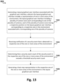
- the processor is further configured to: generate a layout graphical user interface associated with the graphical user interface, wherein the layout graphical user interface includes a representation of one or more areas of the environment, the layout graphical user interface including a plurality of camera icons each corresponding to one of the plurality of cameras, each of the plurality of camera icons having a respective position on the layout graphical user interface corresponding to a respective area in the environment associated with a corresponding one of the plurality of cameras; receive notification of a security event that is detected in a respective one of the one or more areas of the environment; determine that a security event count of the security event in the respective one of the one or more areas of the environment exceeds a threshold security event count; and generate a heat map representation in the respective one of the one or more areas of the environment in the layout graphical user interface.
- Clause 9 The apparatus of any of the preceding clauses, wherein to generate the graphical user interface the processor is further configured to generate security event information in at least one respective camera window, the security information associated with a respective area in the environment associated with the respective camera window.
- the security event information comprises, for a given area, one or any combination of: an occupancy count, an occupancy indicator, a security personnel indicator, a security alert indicator, a security event history, a device count, or a device status list.
- Clause 11 The apparatus of any of the preceding clauses, wherein the graphical user interface is spatially variable relative to a user device in the environment presenting the dashboard based on location information and direction information associated with the user device.
- a method for controlling multi-camera view user interface comprising: generating, for a graphical user interface, a respective camera window for each respective camera of a plurality of cameras in different areas of an environment, wherein the respective camera window outputs a stream captured by the respective camera; arranging the graphical user interface according to a camera window placement scheme based on a layout of the environment, wherein arranging the graphical user interface comprises assigning a first camera window of a first camera of the plurality of cameras a position on the graphical user interface relative to other generated camera windows based on a physical position of an area in the environment associated with the first camera relative to other areas in the environment; and generating, for display, a dashboard comprising the graphical user interface organized according to the camera window placement scheme.
- arranging the graphical user interface according to the camera window placement scheme further comprises: setting a window size of each camera window based on an object size of an object captured by the plurality of cameras such that the object size of the object is equal across each respective camera window of the graphical user interface.
- Clause 17 The method of any of the preceding clauses, further comprising: receiving notification of a security event that is detected in at least one area of the environment; and generating a security event alert in the dashboard.
- Clause 18 The method of any of the preceding clauses, further comprising: receiving notification of a security event that is detected in the area associated with the first camera; and generating a security event alert in the first camera window.
- Clause 19 The method of any of the preceding clauses, further comprising: determining that a security event count in the area associated with the first camera exceeds a threshold security event count; and adjusting an appearance of the first camera window in a heat map view of the graphical user interface such that a first visual representation of the heat map view for the first camera window is different than a second visual representation of the heat map view for other camera windows of the graphical user interface.
- Clause 20 The method of any of the preceding clauses, further comprising: generating a layout graphical user interface associated with the graphical user interface, wherein the layout graphical user interface includes a representation of one or more areas of the environment, the layout graphical user interface including a plurality of camera icons each corresponding to one of the plurality of cameras, each of the plurality of camera icons having a respective position on the layout graphical user interface corresponding to a respective area in the environment associated with a corresponding one of the plurality of cameras; receiving notification of a security event that is detected in a respective one of the one or more areas of the environment; determining that a security event count of the security event in the respective one of the one or more areas of the environment exceeds a threshold security event count; and generating a heat map representation in the respective one of the one or more areas of the environment in the layout graphical user interface.
- generating the graphical user interface further comprises generating security event information in at least one respective camera window, the security information associated with a respective area in the environment associated with the respective camera window.
- the security event information comprises, for a given area, one or any combination of: an occupancy count, an occupancy indicator, a security personnel indicator, a security alert indicator, a security event history, a device count, or a device status list.
- Clause 23 The method of any of the preceding clauses, wherein arranging the graphical user interface according to the camera window placement scheme is spatially variable relative to a user device in the environment presenting the dashboard based on location information and direction information associated with the user device.
- Clause 24 The method of any of the preceding clauses, further comprising presenting, on a display device, the dashboard.
Landscapes
- Engineering & Computer Science (AREA)
- Human Computer Interaction (AREA)
- Physics & Mathematics (AREA)
- General Physics & Mathematics (AREA)
- Multimedia (AREA)
- Signal Processing (AREA)
- Alarm Systems (AREA)
Applications Claiming Priority (1)
| Application Number | Priority Date | Filing Date | Title |
|---|---|---|---|
| US18/194,292 US12424067B2 (en) | 2023-03-31 | 2023-03-31 | Systems and methods for a map-based multi-camera view dashboard |
Publications (2)
| Publication Number | Publication Date |
|---|---|
| EP4440102A1 true EP4440102A1 (de) | 2024-10-02 |
| EP4440102B1 EP4440102B1 (de) | 2025-10-08 |
Family
ID=90717044
Family Applications (1)
| Application Number | Title | Priority Date | Filing Date |
|---|---|---|---|
| EP24168154.3A Active EP4440102B1 (de) | 2023-03-31 | 2024-04-02 | Systeme und verfahren für ein kartenbasiertes mehrkamera-ansichts-dashboard |
Country Status (2)
| Country | Link |
|---|---|
| US (1) | US12424067B2 (de) |
| EP (1) | EP4440102B1 (de) |
Families Citing this family (1)
| Publication number | Priority date | Publication date | Assignee | Title |
|---|---|---|---|---|
| GB2641786A (en) * | 2024-06-13 | 2025-12-17 | Milestone Systems As | Video surveillance method and system |
Citations (4)
| Publication number | Priority date | Publication date | Assignee | Title |
|---|---|---|---|---|
| US20080088706A1 (en) * | 2006-10-13 | 2008-04-17 | Fujixerox Co., Ltd | Interface for browsing and viewing video from multiple cameras simultaneously that conveys spatial and temporal proximity |
| WO2014182898A1 (en) * | 2013-05-09 | 2014-11-13 | Siemens Aktiengesellschaft | User interface for effective video surveillance |
| US20180033153A1 (en) * | 2015-02-20 | 2018-02-01 | Panasonic Intellectual Property Management Co., Ltd. | Tracking assistance device, tracking assistance system, and tracking assistance method |
| US20210216789A1 (en) * | 2015-09-01 | 2021-07-15 | Nec Corporation | Surveillance information generation apparatus, imaging direction estimation apparatus, surveillance information generation method, imaging direction estimation method, and program |
Family Cites Families (6)
| Publication number | Priority date | Publication date | Assignee | Title |
|---|---|---|---|---|
| US20170185277A1 (en) * | 2008-08-11 | 2017-06-29 | Icontrol Networks, Inc. | Automation system user interface |
| US8825392B2 (en) | 2011-06-30 | 2014-09-02 | Navteq B.V. | Map view |
| US9235318B2 (en) | 2012-02-01 | 2016-01-12 | Facebook, Inc. | Transitions among hierarchical user-interface layers |
| CN102929508B (zh) | 2012-10-11 | 2015-04-01 | 中兴通讯股份有限公司 | 一种电子地图触控方法和装置 |
| US10185465B1 (en) * | 2014-03-19 | 2019-01-22 | Symantec Corporation | Techniques for presenting information on a graphical user interface |
| US10750346B1 (en) * | 2019-08-08 | 2020-08-18 | Unisys Corporation | Emergency incident detection platform |
-
2023
- 2023-03-31 US US18/194,292 patent/US12424067B2/en active Active
-
2024
- 2024-04-02 EP EP24168154.3A patent/EP4440102B1/de active Active
Patent Citations (4)
| Publication number | Priority date | Publication date | Assignee | Title |
|---|---|---|---|---|
| US20080088706A1 (en) * | 2006-10-13 | 2008-04-17 | Fujixerox Co., Ltd | Interface for browsing and viewing video from multiple cameras simultaneously that conveys spatial and temporal proximity |
| WO2014182898A1 (en) * | 2013-05-09 | 2014-11-13 | Siemens Aktiengesellschaft | User interface for effective video surveillance |
| US20180033153A1 (en) * | 2015-02-20 | 2018-02-01 | Panasonic Intellectual Property Management Co., Ltd. | Tracking assistance device, tracking assistance system, and tracking assistance method |
| US20210216789A1 (en) * | 2015-09-01 | 2021-07-15 | Nec Corporation | Surveillance information generation apparatus, imaging direction estimation apparatus, surveillance information generation method, imaging direction estimation method, and program |
Also Published As
| Publication number | Publication date |
|---|---|
| US20240331516A1 (en) | 2024-10-03 |
| EP4440102B1 (de) | 2025-10-08 |
| US12424067B2 (en) | 2025-09-23 |
Similar Documents
| Publication | Publication Date | Title |
|---|---|---|
| EP2934004B1 (de) | System und verfahren für virtuelle zonenbasierte kameraparameteraktualisierungen in videoüberwachungssystemen | |
| JP6156665B1 (ja) | 施設内活動分析装置、施設内活動分析システムおよび施設内活動分析方法 | |
| KR101321444B1 (ko) | Cctv 모니터링 시스템 | |
| US10365260B2 (en) | Image based surveillance system | |
| US20110109747A1 (en) | System and method for annotating video with geospatially referenced data | |
| CA2853132C (en) | Video tagging for dynamic tracking | |
| US20190037178A1 (en) | Autonomous video management system | |
| US20120033083A1 (en) | Verfahren zur videoanalyse | |
| US9996237B2 (en) | Method and system for display of visual information | |
| US11651667B2 (en) | System and method for displaying moving objects on terrain map | |
| CN105554440A (zh) | 监控方法和设备 | |
| KR20180007845A (ko) | 3차원 공간분석을 이용한 cctv 카메라 설치위치 선정 방법 | |
| EP4440102B1 (de) | Systeme und verfahren für ein kartenbasiertes mehrkamera-ansichts-dashboard | |
| EP3855749A1 (de) | Systeme und verfahren zur anzeige von video-streams auf einem bildschirm | |
| JP6705102B2 (ja) | 撮像装置の設置支援装置、撮像装置の設置支援方法および映像記録再生装置 | |
| US12283027B2 (en) | PTZ masking control | |
| US10979675B2 (en) | Video monitoring apparatus for displaying event information | |
| WO2011025359A1 (en) | System and method to determine suspicious behavior | |
| JP2020102676A (ja) | 情報処理装置、情報処理方法およびプログラム | |
| US12586456B2 (en) | Systems and methods for providing security system information using augmented reality effects | |
| US20090172600A1 (en) | System and Method of Orienting Building Representations | |
| EP4418209A1 (de) | System und verfahren zur visualisierung der bewegung eines erfassten objekts in einer szene | |
| CN110708498A (zh) | 一种在实景监控画面中标示poi信息的方法及装置 | |
| US20180112988A1 (en) | System and method for displaying points of interest in augmented reality | |
| Yuen et al. | A user-centric control and navigation for augmented virtual environment surveillance application |
Legal Events
| Date | Code | Title | Description |
|---|---|---|---|
| PUAI | Public reference made under article 153(3) epc to a published international application that has entered the european phase |
Free format text: ORIGINAL CODE: 0009012 |
|
| STAA | Information on the status of an ep patent application or granted ep patent |
Free format text: STATUS: REQUEST FOR EXAMINATION WAS MADE |
|
| 17P | Request for examination filed |
Effective date: 20240402 |
|
| AK | Designated contracting states |
Kind code of ref document: A1 Designated state(s): AL AT BE BG CH CY CZ DE DK EE ES FI FR GB GR HR HU IE IS IT LI LT LU LV MC ME MK MT NL NO PL PT RO RS SE SI SK SM TR |
|
| GRAP | Despatch of communication of intention to grant a patent |
Free format text: ORIGINAL CODE: EPIDOSNIGR1 |
|
| STAA | Information on the status of an ep patent application or granted ep patent |
Free format text: STATUS: GRANT OF PATENT IS INTENDED |
|
| RIC1 | Information provided on ipc code assigned before grant |
Ipc: G08B 13/196 20060101ALI20250416BHEP Ipc: H04N 7/18 20060101AFI20250416BHEP |
|
| INTG | Intention to grant announced |
Effective date: 20250430 |
|
| GRAS | Grant fee paid |
Free format text: ORIGINAL CODE: EPIDOSNIGR3 |
|
| GRAA | (expected) grant |
Free format text: ORIGINAL CODE: 0009210 |
|
| STAA | Information on the status of an ep patent application or granted ep patent |
Free format text: STATUS: THE PATENT HAS BEEN GRANTED |
|
| AK | Designated contracting states |
Kind code of ref document: B1 Designated state(s): AL AT BE BG CH CY CZ DE DK EE ES FI FR GB GR HR HU IE IS IT LI LT LU LV MC ME MK MT NL NO PL PT RO RS SE SI SK SM TR |
|
| REG | Reference to a national code |
Ref country code: GB Ref legal event code: FG4D Ref country code: CH Ref legal event code: F10 Free format text: ST27 STATUS EVENT CODE: U-0-0-F10-F00 (AS PROVIDED BY THE NATIONAL OFFICE) Effective date: 20251008 |
|
| P01 | Opt-out of the competence of the unified patent court (upc) registered |
Free format text: CASE NUMBER: UPC_APP_7433_4440102/2025 Effective date: 20250917 |
|
| REG | Reference to a national code |
Ref country code: DE Ref legal event code: R096 Ref document number: 602024000837 Country of ref document: DE |
|
| REG | Reference to a national code |
Ref country code: IE Ref legal event code: FG4D |
|
| REG | Reference to a national code |
Ref country code: NL Ref legal event code: MP Effective date: 20251008 |
|
| REG | Reference to a national code |
Ref country code: AT Ref legal event code: MK05 Ref document number: 1845860 Country of ref document: AT Kind code of ref document: T Effective date: 20251008 |
|
| PG25 | Lapsed in a contracting state [announced via postgrant information from national office to epo] |
Ref country code: NL Free format text: LAPSE BECAUSE OF FAILURE TO SUBMIT A TRANSLATION OF THE DESCRIPTION OR TO PAY THE FEE WITHIN THE PRESCRIBED TIME-LIMIT Effective date: 20251008 |
|
| PG25 | Lapsed in a contracting state [announced via postgrant information from national office to epo] |
Ref country code: ES Free format text: LAPSE BECAUSE OF FAILURE TO SUBMIT A TRANSLATION OF THE DESCRIPTION OR TO PAY THE FEE WITHIN THE PRESCRIBED TIME-LIMIT Effective date: 20251008 |
|
| REG | Reference to a national code |
Ref country code: LT Ref legal event code: MG9D |
|
| PG25 | Lapsed in a contracting state [announced via postgrant information from national office to epo] |
Ref country code: NO Free format text: LAPSE BECAUSE OF FAILURE TO SUBMIT A TRANSLATION OF THE DESCRIPTION OR TO PAY THE FEE WITHIN THE PRESCRIBED TIME-LIMIT Effective date: 20260108 |
|
| PG25 | Lapsed in a contracting state [announced via postgrant information from national office to epo] |
Ref country code: HR Free format text: LAPSE BECAUSE OF FAILURE TO SUBMIT A TRANSLATION OF THE DESCRIPTION OR TO PAY THE FEE WITHIN THE PRESCRIBED TIME-LIMIT Effective date: 20251008 Ref country code: FI Free format text: LAPSE BECAUSE OF FAILURE TO SUBMIT A TRANSLATION OF THE DESCRIPTION OR TO PAY THE FEE WITHIN THE PRESCRIBED TIME-LIMIT Effective date: 20251008 Ref country code: AT Free format text: LAPSE BECAUSE OF FAILURE TO SUBMIT A TRANSLATION OF THE DESCRIPTION OR TO PAY THE FEE WITHIN THE PRESCRIBED TIME-LIMIT Effective date: 20251008 |
|
| PG25 | Lapsed in a contracting state [announced via postgrant information from national office to epo] |
Ref country code: RS Free format text: LAPSE BECAUSE OF FAILURE TO SUBMIT A TRANSLATION OF THE DESCRIPTION OR TO PAY THE FEE WITHIN THE PRESCRIBED TIME-LIMIT Effective date: 20260108 |
|
| PG25 | Lapsed in a contracting state [announced via postgrant information from national office to epo] |
Ref country code: IS Free format text: LAPSE BECAUSE OF FAILURE TO SUBMIT A TRANSLATION OF THE DESCRIPTION OR TO PAY THE FEE WITHIN THE PRESCRIBED TIME-LIMIT Effective date: 20260208 |
|
| PG25 | Lapsed in a contracting state [announced via postgrant information from national office to epo] |
Ref country code: PT Free format text: LAPSE BECAUSE OF FAILURE TO SUBMIT A TRANSLATION OF THE DESCRIPTION OR TO PAY THE FEE WITHIN THE PRESCRIBED TIME-LIMIT Effective date: 20260209 |
|
| PG25 | Lapsed in a contracting state [announced via postgrant information from national office to epo] |
Ref country code: PL Free format text: LAPSE BECAUSE OF FAILURE TO SUBMIT A TRANSLATION OF THE DESCRIPTION OR TO PAY THE FEE WITHIN THE PRESCRIBED TIME-LIMIT Effective date: 20251008 |
|
| PG25 | Lapsed in a contracting state [announced via postgrant information from national office to epo] |
Ref country code: LV Free format text: LAPSE BECAUSE OF FAILURE TO SUBMIT A TRANSLATION OF THE DESCRIPTION OR TO PAY THE FEE WITHIN THE PRESCRIBED TIME-LIMIT Effective date: 20251008 |
|
| PG25 | Lapsed in a contracting state [announced via postgrant information from national office to epo] |
Ref country code: BG Free format text: LAPSE BECAUSE OF FAILURE TO SUBMIT A TRANSLATION OF THE DESCRIPTION OR TO PAY THE FEE WITHIN THE PRESCRIBED TIME-LIMIT Effective date: 20251008 |
|
| PG25 | Lapsed in a contracting state [announced via postgrant information from national office to epo] |
Ref country code: LT Free format text: LAPSE BECAUSE OF FAILURE TO SUBMIT A TRANSLATION OF THE DESCRIPTION OR TO PAY THE FEE WITHIN THE PRESCRIBED TIME-LIMIT Effective date: 20251008 |
|
| PG25 | Lapsed in a contracting state [announced via postgrant information from national office to epo] |
Ref country code: SM Free format text: LAPSE BECAUSE OF FAILURE TO SUBMIT A TRANSLATION OF THE DESCRIPTION OR TO PAY THE FEE WITHIN THE PRESCRIBED TIME-LIMIT Effective date: 20251008 |
|
| PG25 | Lapsed in a contracting state [announced via postgrant information from national office to epo] |
Ref country code: DK Free format text: LAPSE BECAUSE OF FAILURE TO SUBMIT A TRANSLATION OF THE DESCRIPTION OR TO PAY THE FEE WITHIN THE PRESCRIBED TIME-LIMIT Effective date: 20251008 |
|
| PG25 | Lapsed in a contracting state [announced via postgrant information from national office to epo] |
Ref country code: IT Free format text: LAPSE BECAUSE OF FAILURE TO SUBMIT A TRANSLATION OF THE DESCRIPTION OR TO PAY THE FEE WITHIN THE PRESCRIBED TIME-LIMIT Effective date: 20251008 |
|
| PGFP | Annual fee paid to national office [announced via postgrant information from national office to epo] |
Ref country code: DE Payment date: 20260421 Year of fee payment: 3 |
|
| PG25 | Lapsed in a contracting state [announced via postgrant information from national office to epo] |
Ref country code: EE Free format text: LAPSE BECAUSE OF FAILURE TO SUBMIT A TRANSLATION OF THE DESCRIPTION OR TO PAY THE FEE WITHIN THE PRESCRIBED TIME-LIMIT Effective date: 20251008 |
|
| PG25 | Lapsed in a contracting state [announced via postgrant information from national office to epo] |
Ref country code: CZ Free format text: LAPSE BECAUSE OF FAILURE TO SUBMIT A TRANSLATION OF THE DESCRIPTION OR TO PAY THE FEE WITHIN THE PRESCRIBED TIME-LIMIT Effective date: 20251008 |
|
| PGFP | Annual fee paid to national office [announced via postgrant information from national office to epo] |
Ref country code: FR Payment date: 20260423 Year of fee payment: 3 |
|
| PG25 | Lapsed in a contracting state [announced via postgrant information from national office to epo] |
Ref country code: SK Free format text: LAPSE BECAUSE OF FAILURE TO SUBMIT A TRANSLATION OF THE DESCRIPTION OR TO PAY THE FEE WITHIN THE PRESCRIBED TIME-LIMIT Effective date: 20251008 |
|
| PG25 | Lapsed in a contracting state [announced via postgrant information from national office to epo] |
Ref country code: SE Free format text: LAPSE BECAUSE OF FAILURE TO SUBMIT A TRANSLATION OF THE DESCRIPTION OR TO PAY THE FEE WITHIN THE PRESCRIBED TIME-LIMIT Effective date: 20251008 |
|
| PLBE | No opposition filed within time limit |
Free format text: ORIGINAL CODE: 0009261 |
|
| STAA | Information on the status of an ep patent application or granted ep patent |
Free format text: STATUS: NO OPPOSITION FILED WITHIN TIME LIMIT |