EP4439887A1 - Bracket and cell contact system assembly - Google Patents
Bracket and cell contact system assembly Download PDFInfo
- Publication number
- EP4439887A1 EP4439887A1 EP23220677.1A EP23220677A EP4439887A1 EP 4439887 A1 EP4439887 A1 EP 4439887A1 EP 23220677 A EP23220677 A EP 23220677A EP 4439887 A1 EP4439887 A1 EP 4439887A1
- Authority
- EP
- European Patent Office
- Prior art keywords
- limiting
- chamfer
- elastic plate
- post
- limiting head
- Prior art date
- Legal status (The legal status is an assumption and is not a legal conclusion. Google has not performed a legal analysis and makes no representation as to the accuracy of the status listed.)
- Pending
Links
- 238000005452 bending Methods 0.000 claims description 37
- 230000007423 decrease Effects 0.000 claims description 2
- 230000000694 effects Effects 0.000 description 19
- 238000004519 manufacturing process Methods 0.000 description 9
- 238000010586 diagram Methods 0.000 description 5
- 230000009286 beneficial effect Effects 0.000 description 3
- 230000005489 elastic deformation Effects 0.000 description 3
- 239000000463 material Substances 0.000 description 3
- 230000007704 transition Effects 0.000 description 3
- 230000007547 defect Effects 0.000 description 2
- 238000000034 method Methods 0.000 description 2
- 230000002950 deficient Effects 0.000 description 1
- 238000003908 quality control method Methods 0.000 description 1
Images


Classifications
-
- H—ELECTRICITY
- H02—GENERATION; CONVERSION OR DISTRIBUTION OF ELECTRIC POWER
- H02G—INSTALLATION OF ELECTRIC CABLES OR LINES, OR OF COMBINED OPTICAL AND ELECTRIC CABLES OR LINES
- H02G3/00—Installations of electric cables or lines or protective tubing therefor in or on buildings, equivalent structures or vehicles
- H02G3/30—Installations of cables or lines on walls, floors or ceilings
- H02G3/32—Installations of cables or lines on walls, floors or ceilings using mounting clamps
-
- H—ELECTRICITY
- H01—ELECTRIC ELEMENTS
- H01M—PROCESSES OR MEANS, e.g. BATTERIES, FOR THE DIRECT CONVERSION OF CHEMICAL ENERGY INTO ELECTRICAL ENERGY
- H01M50/00—Constructional details or processes of manufacture of the non-active parts of electrochemical cells other than fuel cells, e.g. hybrid cells
- H01M50/20—Mountings; Secondary casings or frames; Racks, modules or packs; Suspension devices; Shock absorbers; Transport or carrying devices; Holders
- H01M50/298—Mountings; Secondary casings or frames; Racks, modules or packs; Suspension devices; Shock absorbers; Transport or carrying devices; Holders characterised by the wiring of battery packs
-
- H—ELECTRICITY
- H01—ELECTRIC ELEMENTS
- H01M—PROCESSES OR MEANS, e.g. BATTERIES, FOR THE DIRECT CONVERSION OF CHEMICAL ENERGY INTO ELECTRICAL ENERGY
- H01M50/00—Constructional details or processes of manufacture of the non-active parts of electrochemical cells other than fuel cells, e.g. hybrid cells
- H01M50/50—Current conducting connections for cells or batteries
- H01M50/502—Interconnectors for connecting terminals of adjacent batteries; Interconnectors for connecting cells outside a battery casing
-
- H—ELECTRICITY
- H02—GENERATION; CONVERSION OR DISTRIBUTION OF ELECTRIC POWER
- H02G—INSTALLATION OF ELECTRIC CABLES OR LINES, OR OF COMBINED OPTICAL AND ELECTRIC CABLES OR LINES
- H02G3/00—Installations of electric cables or lines or protective tubing therefor in or on buildings, equivalent structures or vehicles
- H02G3/02—Details
- H02G3/04—Protective tubing or conduits, e.g. cable ladders or cable troughs
- H02G3/0456—Ladders or other supports
-
- H—ELECTRICITY
- H02—GENERATION; CONVERSION OR DISTRIBUTION OF ELECTRIC POWER
- H02G—INSTALLATION OF ELECTRIC CABLES OR LINES, OR OF COMBINED OPTICAL AND ELECTRIC CABLES OR LINES
- H02G3/00—Installations of electric cables or lines or protective tubing therefor in or on buildings, equivalent structures or vehicles
- H02G3/30—Installations of cables or lines on walls, floors or ceilings
Definitions
- the present application relates to the field of a battery including a bracket that prevents wire harnesses from falling off, and particularly to a bracket and a cell contact system (CCS) assembly.
- CCS cell contact system
- CCS cell contact system
- the present application provides a bracket and a cell contact system (CCS) assembly.
- CCS cell contact system
- an embodiment of the present application provides a bracket, the bracket includes a bracket body, an elastic member and a position-limiting member.
- a fixed end of the elastic member is assembled on the bracket body.
- a fixed end of the position-limiting member is assembled on the bracket body.
- the position-limiting member, the elastic member, and the bracket body enclose and define a position-limiting space.
- An end of the elastic member away from the fixed end of the elastic member is a free end.
- An end of the position-limiting member away from the fixed end of the position-limiting member is a position-limiting end.
- a guiding opening is defined between the free end of the elastic member and the position-limiting end of the position-limiting member, and is communicated with the position-limiting space. The guiding opening has a size being adjusted by changing a degree of deformation of the free end of the elastic member.
- an embodiment of the present application provides a cell contact system assembly including a cell contact system body and at least one bracket mentioned above.
- the bracket is disposed on the cell contact system body, and the position-limiting member and the elastic member are assembled in a groove channel of the bracket body.
- the wire harnesses of the CCS assembly can be fixed. An effect of fixing is good, and the wire harnesses are not easy to fall off.
- meanings of reference labels are as follows: 1, elastic plate post; 11, first chamfer; 12, second chamfer; 13, third chamfer; 2, elastic plate; 21, eighth chamfer; 3, position-limiting head post; 31, sixth chamfer; 32, seventh chamfer; 4, position-limiting head; 41, fourth chamfer; 42, fifth chamfer; 43, first portion; 44,second portion; 5, bracket body; 51, groove channel; 6, position-limiting space; 7, guiding opening; 8, elastic member; 9, position-limiting member.
- orientation or location relationships such as “up”, “down”, “left”, “right”, “vertical”, “horizontal”, “top”, “bottom”, “ inside”, and “outside” etc. are based on orientation or location relationships shown in drawings, which are only for a convenience of description and simplified operation, rather than indicating or implying that devices or elements referred to must have a specific orientation, be constructed and operated in a specific orientation, so it cannot be understood as a limitation of the present disclosure.
- the present application is shown in FIGs. 1 to 4 , and the present application discloses a bracket including an elastic member 8 and a position-limiting member 9.
- the elastic member 8 and the position-limiting member 9 are both strip-shaped or plate-shaped.
- the elastic member 8 itself is elastically deformable or partly elastically deformable.
- the elastic member 8 has a fixed end, the fixed end of the elastic member 8 is assembled on the bracket body 5.
- the position-limiting member 9 also has a fixed end, the fixed end of the position-limiting member 9 is assembled on the bracket body 5.
- the position-limiting member 9, the elastic member 8, and the bracket body 5 enclose and define a position-limiting space 6 configured to accommodate wire harnesses. An end of the elastic member 8 away from the fixed end of the elastic member is a free end.
- An end of the position-limiting member 9 away from the fixed end of the position-limiting member is a position-limiting end.
- a guiding opening 7 is defined between the free end of the elastic member 8 and the position-limiting end of the position-limiting member 9, and the guiding opening 7 is communicated with the position-limiting space 6.
- the guiding opening 7 has a size being adjusted by changing a degree of deformation of the free end of the elastic member 8.
- the free end of the elastic member 8 can abut against the position-limiting end of the position-limiting member 9 in a case that the free end of the elastic member 8 is elastically deformed towards a direction away from the position-limiting space 6.
- an effect of closing the guiding opening 7 can be achieved in a case that there are too many wire harnesses in the position-limiting space 6, so as to achieve an effect of preventing the wire harnesses from falling off.
- the elastic member 8 and/or the position-limiting member 9 is provided with at least one bending portion, so that the elastic member 8 and the position-limiting member 9 are bent towards each other to define the guiding opening 7.
- the bending portion can be designed according to different structures of bracket bodies 5.
- the elastic member 8 and the position-limiting member 9 can define the position-limiting space, it is beneficial to form the guiding opening 7, and an effect of fixing the wire harnesses can be achieved.
- the guiding opening 7 has a width less than a diameter of the wire harness.
- the size of the guiding opening 7 is adjusted by changing the degree of deformation of the elastic member 8, so as to achieve passage and fixation of the wire harnesses.
- the free end of the elastic member 8 is elastically deforms toward inside of the position-limiting space 6.
- the guiding opening 7 becomes larger, so as to realize the passage of the wire harnesses.
- the elastic member 8 is squeezed by the wire harnesses in the position-limiting space 6, the free end of the elastic member 8 is elastically deformed toward a direction away from the position-limiting space 6.
- FIGs. 1 to 4 An embodiment 1 of the present application is shown in FIGs. 1 to 4 .
- the elastic member 8 includes an elastic plate post 1 and an elastic plate 2, and the elastic plate 2 and the elastic plate post 1 are integrally formed by bending.
- the position-limiting member 9 includes a position-limiting head post 3 and a position-limiting head 4, and the position-limiting head post 3 and the position-limiting head 4 are integrally formed by bending.
- the elastic plate 2 and the position-limiting head 4 are bent towards each other.
- An end of the elastic plate post 1 away from the elastic plate 2 and an end of the position-limiting head post 3 away from the position-limiting head 4 are both assembled on the bracket body 5.
- the elastic plate post 1 is a fixed end of the elastic plate 2.
- the guiding opening 7 is defined between a free end of the elastic plate 2 and a position-limiting end of the position-limiting head 4. Projections of the free end of the elastic plate 2 and the position-limiting end of the position-limiting head 4 on the bracket body 5 at least partially overlap with each other, so that the elastic member 8 and the position-limiting member 9 are bend towards each other.
- the wire harnesses enter into the position-limiting space 6 from the guiding opening 7 of the bracket body 5, which is convenient for persons or equipments to operate the wire harnesses.
- a snap-fit structure with good effect of anti-falling off for the wire harness is achieved.
- the position-limiting head post 3 and the elastic plate post 1 are vertically assembled on the bracket body 5, which is only a preferred embodiment, so as to provide better supporting force for the elastic plate 2 and the position-limiting head 4.
- the elastic plate post 1 and the position-limiting head post 3 may not be vertically assembled on the bracket body 5, and may be slightly tilted, as long as selfstability is satisfied.
- the position-limiting head post 3 and the elastic plate post 1 may also be provided with a structure of a trapezoidal frustum, so as to improve aesthetics and practicality, and further improve stability of fixing the wire harnesses.
- An angle between the elastic plate 2 and the elastic plate post 1 is set to be less than 90° , so that the elastic plate 2 has a stronger reset effect in a case that the elastic plate rotates itself.
- the elastic plate 2 has a length X1 in the only one longitudinal reference plane.
- the position-limiting head 4 has a length X2 in the only one longitudinal reference plane, and X1 >X2. Since the length of the position-limiting head 4 is less than that of the elastic plate 2, stability of the position-limiting head 4 is stronger than that of the elastic plate 2, which helps to limit the position of the elastic plate 2.
- the position-limiting head post 3, the elastic plate post 1, the elastic plate 2, and the position-limiting head 4 have a relation as follows, H1 > X>H2>Y, which is helpful to realize a snap-fit structure that is relatively stable.
- the snap-fit structure has a function of clamping and is effective for anti-falling off.
- the elastic plate 2 in the only one longitudinal reference plane, includes a point C that is adjacent to the guiding opening 7 and is closest to a point A of the position-limiting head 4.
- the elastic plate 2 further includes a point E that is adjacent to the guiding opening 7 and is closest to a point D of the position-limiting head post 3.
- a distance between the point A and the point C is less than a preset value.
- a distance between the point D and the point E is less than a preset value.
- the wire harnesses can enter from spaces between the point A and the point C, and between the point D and the point E by increasing the guiding opening 7.
- the preset value is the diameter of the wire harness, and the size of the guiding opening is adaptively adjusted according to the diameter of the wire harness.
- the length, the width, and the height of the elastic plate post 1 are 1. 5mm ⁇ 1. 5mm ⁇ 9mm.
- the length, the width, and the height of the position-limiting head post 3 are 1.5mm ⁇ 1.5mm ⁇ 8.39mm.
- the length, the width, and the height of the elastic plate 2 are 1mm ⁇ 1.5mm ⁇ 8.9mm.
- the length, the width, and the height of the position-limiting head 4 are 1mm ⁇ 1.5mm ⁇ 2mm.
- the bracket body 5 is provided with a groove channel 51.
- the length, the width, and the height of the groove channel 51 are 1.5mm ⁇ 10mm ⁇ 1.5mm.
- depths of the elastic plate post 1 and the position-limiting head post 3 inserting into the channel 51 is 1.5mm.
- a bending side angle between the elastic plate post 1 and the elastic plate 2 is less than a bending side angle between the position-limiting head post 3 and the position-limiting head 4.
- the elastic plate 2 is limited between the position-limiting head 4 and the bracket body 5, which helps to improve a problem of breaking of the elastic plate 2 caused by excessive rotation of the elastic plate 2.
- the bending side angle between the elastic plate post 1 and the elastic plate 2 is set to be 75°
- the bending side angle between the position-limiting head post 3 and the position-limiting head 4 is set to be 90° .
- Stabilities of the position-limiting head post 3 and the position-limiting head 4 are higher, and elasticity of the elastic plate 2 is better.
- the bending angle can be slightly changed according to actual situation, which is not specifically limited in the embodiment.
- the elastic plate 2 can be pressed by hand to make the wire harnesses slide into the position-limiting space 6 from the guiding opening 7; or, the elastic plate 2 is directly squeezed downward by the wire harness, and the elastic plate 2 rotates towards a direction away from the position-limiting head 4 under force.
- the distance between the point A and the point C and the distance between the point D and the point E increase, and the wire harness easily enters into the position-limiting space 6.
- the elastic plate 2 automatically resets towards the direction adjacent to the position-limiting head 4.
- the wire harness shakes to provide the elastic plate 2 with a force to rotate towards a direction of the position-limiting head 4, the distance between the point A and the point C and the distance between the point D and the point E decrease. The distance between the point A and the point C can even become 0, that is, the elastic plate 2 and the position-limiting head 4 contact with each other. The wire harness is even more impossible to fall off, so as to achieve an effect of anti-falling off.
- back bending sides of the elastic plate post 1 and the elastic plate 2 are provided with a first chamfer 11 and a second chamfer 12, respectively.
- a distance between the first chamfer 11 and the position-limiting head 4 is greater than a distance between the second chamfer 12 and the position-limiting head 4.
- a chamfer radius of the first chamfer 11 is less than a chamfer radius of the second chamfer 12.
- a bending side between the elastic plate post 1 and the elastic plate 2 is provided with a third chamfer 13, a chamfer radius of the third chamfer 13 is the same as the chamfer radius of the first chamfer 11.
- a side of the position-limiting head 4 adjacent to the guiding opening 7 is provided with a fourth chamfer 41 and a fifth chamfer 42.
- a distance between the fourth chamfer 41 and the elastic plate post 1 is less than a distance between the fifth chamfer 42 and the elastic plate post 1.
- a chamfer radius of the fourth chamfer 41 and a chamfer radius of the fifth chamfer 42 are both the same as the chamfer radius of the second chamfer 12.
- a back bending side between the position-limiting head post 3 and the position-limiting head 4 is provided with a sixth chamfer 31.
- a bending side between the position-limiting head post 3 and the position-limiting head 4 is provided with a seventh chamfer 32.
- a chamfer radius of the sixth chamfer 31 and a chamfer radius of the seventh chamfer 32 are the same as the chamfer radius of the first chamfer 11.
- a smooth transition of the back bending side between the position-limiting head post 3 and the position-limiting head 4 is realized.
- the bending side between the position-limiting head post 3 and the position-limiting head 4 is provided with a chamfer, thereby preventing the wire harnesses disposed inside from excessive wear.
- a side of the elastic plate 2 adjacent to the position-limiting head 4 is provided with a eighth chamfer 21, and a chamfer radius of the eighth chamfer 21 is the same as the chamfer radius of the second chamfer 12.
- chamfering radiuses of the first chamfer 11, the third chamfer 13, the sixth chamfer 31, and the seventh chamfer 32 are set to be 0.5 mm.
- Chamfering radiuses of the second chamfer 12, the fourth chamfer 41, the fifth chamfer 42, and the eighth chamfer 21 are set to be 1 mm.
- the first chamfer 11 and the sixth chamfer 31 are set to be same, so that bending angles of both are same and are 90°.
- the elastic plate 2 is further bent towards the position-limiting space 6, the second chamfer 12 is added, and a bending angle of the second chamfer 12 is less than 90°. Therefore, the elastic plate 2 is lower than the position-limiting head 4 after being bent for a second time.
- the fourth chamfer 41, the fifth chamfer 42, and the eighth chamfer 21 help to improve surface smoothness, and improve fluency of entry of the wire harnesses.
- chamfering radiuses may vary according to an actual bending angle of the position-limiting head post 3 and the elastic plate post 1, which is not specifically limited in the embodiment.
- the position-limiting member 9 includes a position-limiting head post 3 and a position-limiting head 4.
- the position-limiting head post 3 and the position-limiting head 4 are integrally formed by bending.
- the position-limiting head 4 is bent towards a direction of the elastic member 8 to form a position-limiting end.
- the guiding opening 7 is defined between the free end of the elastic member 8 and the position-limiting end of the position-limiting head 4.
- An end of the position-limiting head post 3 away from the position-limiting head 4 is assembled on the bracket body 5.
- the elastic member 8 is directly assembled on the bracket body 5.
- the position-limiting member 9 is bent towards the direction of the elastic member 8, the elastic member 8 is directly assembled on the bracket body 5.
- the wire harnesses enter the position-limiting space 6 from a side of the bracket body 5 adjacent to the elastic member 8.
- a structure of the guiding opening 7 at one side can be formed, stability is improved, and effects of clamping and anti-falling off for the wire harnesses can be satisfied.
- the position-limiting head post 3 and the elastic member 8 are both vertically assembled on the bracket body 5
- the height of the position-limiting head post 3 is greater than the height of the elastic member 8, and the angle between the position-limiting head 4 and the position-limiting head post 3 is less than 90°.
- the position-limiting space 6 is in a shape of a right-angled trapezoid
- the length of the position-limiting head 4 is greater than an assembly distance between the elastic member 8 and the position-limiting head post 3.
- the position-limiting end of the position-limiting head 4 is lower than the free end of the elastic member 8, so as to limit the elastic member 8, and prevent the elastic member 8 from elastically deforming towards the direction away from the position-limiting space 6 so that the guiding opening 7 becomes larger, thereby preventing the wiring harness falling off from the position-limiting space 6.
- the elastic member 8 may be the elastic plate post 1 in the embodiment 1, and the position-limiting head 4 may include a first portion 43 and a second portion 44 connected to each other.
- the first portion 43 is connected to the position-limiting head post 3 and extends towards the elastic member 8.
- the angle between the first portion 43 and the position-limiting head post 3 is less than 90°.
- the first portion 43 has a length that is greater than the assembly distance between the elastic member 8 and the position-limiting head post 3.
- the second portion 44 includes the position-limiting end and is bent towards the elastic member 8.
- the second portion 44 is disposed at a side of the elastic member 8 away from the position-limiting head post 3.
- the first portion 43 and the second portion 44 are integrally formed by bending.
- the guiding opening 7 is defined between the free end of the elastic member 8 and the position-limiting end of the second portion 44.
- the elastic member 8 may not be vertically assembled on the bracket body 5, and in this situation, the position-limiting head post 3 is not vertically assembled in the bracket body 5 either. There is one bending between the position-limiting head post 3 and the position-limiting head 4, so that a structure of the position-limiting space 6 is in a shape of triangle of which an angle and a side length are not specifically limited. It is only necessary for the position-limiting end of the position-limiting head 4 to be lower than the free end of the elastic member 8, thereby preventing the wire harnesses from falling off from the position-limiting space 6.
- the position-limiting space 6 enclosed by the elastic member 8, the position-limiting member 9 and the bracket body 5 can also be in a shape of a polygon, a circle or an ellipse, so as to satisfy an effect of anti-falling off of the guiding opening 7.
- the present application further provides a cell contact system (CCS) assembly including a CCS body and at least one bracket.
- the bracket is disposed on the CCS body.
- the bracket body 5 is provided with a groove channel 51 in which the elastic member 8 and the position-limiting member 9 are assembled.
- the wire harnesses of the CCS assembly can be fixed with one or more bracket, so as to improve it that the wire harness grooves are directly defined in the bracket of the CCS.
- Complexity of plastic bracket structures of the CCS is reduced. Efficiency of mold-opening is improved, materials of plastic brackets of the CCS is reduced, and weight of the CCS is reduced.
- bracket and the cell contact system provided in the embodiment of the present application have following technical effects.
Landscapes
- Chemical & Material Sciences (AREA)
- Chemical Kinetics & Catalysis (AREA)
- Electrochemistry (AREA)
- General Chemical & Material Sciences (AREA)
- Engineering & Computer Science (AREA)
- Architecture (AREA)
- Civil Engineering (AREA)
- Structural Engineering (AREA)
- Installation Of Indoor Wiring (AREA)
- Supports For Pipes And Cables (AREA)
Abstract
The present application provides a bracket and a cell contact system assembly. The bracket includes a bracket body, an elastic member and a position-limiting member. A fixed end of the elastic member and a fixed end of the position-limiting member are assembled on the bracket body. The position-limiting member, the elastic member and the bracket body enclose to define a position-limiting space. An end of the elastic member away from the fixed end of the elastic member is a free end. An end of the position-limiting member away from the fixed end of the position-limiting member is a position-limiting end. A guiding opening defined between the free end of the elastic member and the position-limiting end of the position-limiting member is communicated with the position-limiting space. The guiding opening has a size being adjusted by changing a degree of deformation of the free end of the elastic member.
Description
- The present application relates to the field of a battery including a bracket that prevents wire harnesses from falling off, and particularly to a bracket and a cell contact system (CCS) assembly.
- Currently, most of collecting wire harnesses of a cell contact system (CCS) fix wire harnesses with ties, and some of the collecting wire harnesses of the CCS fix the wire harnesses with wire harness grooves defined in plastic brackets of the CCS. These two fixing methods have following defects.
- 1. Using ties to fix the wire harnesses increases production processes, reduces production efficiency, and relatively increases labor costs, which is not conducive to highefficiency production of industrialization.
- 2. Using the wire harness grooves to fix the wire harnesses increases complexity of structures of the plastic brackets of the CCS, and increases difficulty of making mold. Materials required for the plastic brackets of the CCS are increased. Weights and costs of the plastic brackets are increased. Defective rates of products are increased under strict conditions of quality control.
- In order to overcome at least one defect described in prior art, the present application provides a bracket and a cell contact system (CCS) assembly. The method of fixing with ties or wire harness grooves is improved. Labor costs are reduced. Mold-making can be produced individually. That the structures such as the wire harness grooves increase production difficulty are improved, thus improving increase in production costs.
- In a first aspect, an embodiment of the present application provides a bracket, the bracket includes a bracket body, an elastic member and a position-limiting member. A fixed end of the elastic member is assembled on the bracket body. A fixed end of the position-limiting member is assembled on the bracket body. The position-limiting member, the elastic member, and the bracket body enclose and define a position-limiting space. An end of the elastic member away from the fixed end of the elastic member is a free end. An end of the position-limiting member away from the fixed end of the position-limiting member is a position-limiting end. A guiding opening is defined between the free end of the elastic member and the position-limiting end of the position-limiting member, and is communicated with the position-limiting space. The guiding opening has a size being adjusted by changing a degree of deformation of the free end of the elastic member.
- By adopting solutions mentioned above, passage and an effect of fixation and anti-falling off of wire harnesses are achieved by elastic deformation of the elastic member itself.
- In a second aspect, an embodiment of the present application provides a cell contact system assembly including a cell contact system body and at least one bracket mentioned above. The bracket is disposed on the cell contact system body, and the position-limiting member and the elastic member are assembled in a groove channel of the bracket body.
- By adopting solutions mentioned above, the wire harnesses of the CCS assembly can be fixed. An effect of fixing is good, and the wire harnesses are not easy to fall off.
- In summary, the bracket provided in the embodiment of the present application has following technical effects.
- 1. The elastic member, the position-limiting member, and the bracket body enclose and define the position-limiting space. The position-limiting space can accommodate single wire harness or a plurality of wire harnesses, so that an fixing effect of the wire harnesses can be realized. Overall structure of the bracket is simple, mold-making can be produced individually, and production efficiency is high.
- 2. The elastic member is limited by the position-limiting member, which prevents the elastic member from being damaged or broken due to excessive force in a case that the elastic member is elastically deformed towards the direction away from the position-limiting space. Meanwhile, the guiding opening can be closed to prevent the wire harnesses from falling off the position-limiting space.
- 3. The elastic member and the position-limiting member are convenient to be assembled. There is no need to increase labor budgets. Labor costs can be saved in comparison with a fixing manner with the ties.
-
-
FIG. 1 is a three-dimensional structural schematic diagram of a snap-fit inembodiment 1 of the present application. -
FIG. 2 is a structural schematic diagram of chamfers of the snap-fit inembodiment 1 of the present application. -
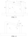
FIG. 3 is a schematic diagram of the snap-fit inembodiment 1 of the present application in a longitudinal reference plane with a dimension annotation. -
FIG. 4 is a structural schematic diagram of the snap-fit inembodiment 1 of the present application in the longitudinal reference plane. -
FIG. 5 is a structural schematic diagram of a snap-fit in anembodiment 2 of the present application. - Herein, meanings of reference labels are as follows: 1, elastic plate post; 11, first chamfer; 12, second chamfer; 13, third chamfer; 2, elastic plate; 21, eighth chamfer; 3, position-limiting head post; 31, sixth chamfer; 32, seventh chamfer; 4, position-limiting head; 41, fourth chamfer; 42, fifth chamfer; 43, first portion; 44,second portion; 5, bracket body; 51, groove channel; 6, position-limiting space; 7, guiding opening; 8, elastic member; 9, position-limiting member.
- In the description of the present application, it should be noted that the terms indicating orientation or location relationships such as "up", "down", "left", "right", "vertical", "horizontal", "top", "bottom", " inside", and "outside" etc. are based on orientation or location relationships shown in drawings, which are only for a convenience of description and simplified operation, rather than indicating or implying that devices or elements referred to must have a specific orientation, be constructed and operated in a specific orientation, so it cannot be understood as a limitation of the present disclosure.
- Unless otherwise defined, all technical and scientific terms used herein have the same meaning as commonly understood by one of ordinary skill in the technical field of the present application. Terms used herein in the specification of the present application are only for the purpose of describing specific embodiments only and are not intended to limit the present application.
- The present application is shown in
FIGs. 1 to 4 , and the present application discloses a bracket including anelastic member 8 and a position-limitingmember 9. Theelastic member 8 and the position-limitingmember 9 are both strip-shaped or plate-shaped. Theelastic member 8 itself is elastically deformable or partly elastically deformable. Theelastic member 8 has a fixed end, the fixed end of theelastic member 8 is assembled on thebracket body 5. The position-limitingmember 9 also has a fixed end, the fixed end of the position-limitingmember 9 is assembled on thebracket body 5. The position-limitingmember 9, theelastic member 8, and thebracket body 5 enclose and define a position-limitingspace 6 configured to accommodate wire harnesses. An end of theelastic member 8 away from the fixed end of the elastic member is a free end. An end of the position-limitingmember 9 away from the fixed end of the position-limiting member is a position-limiting end. A guidingopening 7 is defined between the free end of theelastic member 8 and the position-limiting end of the position-limitingmember 9, and the guidingopening 7 is communicated with the position-limitingspace 6. The guidingopening 7 has a size being adjusted by changing a degree of deformation of the free end of theelastic member 8. - The free end of the
elastic member 8 can abut against the position-limiting end of the position-limitingmember 9 in a case that the free end of theelastic member 8 is elastically deformed towards a direction away from the position-limitingspace 6. Thus, an effect of closing the guidingopening 7 can be achieved in a case that there are too many wire harnesses in the position-limitingspace 6, so as to achieve an effect of preventing the wire harnesses from falling off. Theelastic member 8 and/or the position-limitingmember 9 is provided with at least one bending portion, so that theelastic member 8 and the position-limitingmember 9 are bent towards each other to define the guidingopening 7. The bending portion can be designed according to different structures ofbracket bodies 5. Thus, theelastic member 8 and the position-limitingmember 9 can define the position-limiting space, it is beneficial to form the guidingopening 7, and an effect of fixing the wire harnesses can be achieved. - The guiding
opening 7 has a width less than a diameter of the wire harness. The size of the guidingopening 7 is adjusted by changing the degree of deformation of theelastic member 8, so as to achieve passage and fixation of the wire harnesses. In a case that the wire harnesses pass through theguide opening 7 and enter into the position-limitingspace 6, the free end of theelastic member 8 is elastically deforms toward inside of the position-limitingspace 6. In this situation, the guidingopening 7 becomes larger, so as to realize the passage of the wire harnesses. In a case that theelastic member 8 is squeezed by the wire harnesses in the position-limitingspace 6, the free end of theelastic member 8 is elastically deformed toward a direction away from the position-limitingspace 6. In this situation, the guidingopening 7 becomes smaller, the free end of theelastic member 8 abuts against a position-limiting end of the position-limitingmember 9 to achieve anti-falling off of the wire harnesses. Thus, passage and fixation of the wire harnesses can be achieved by elastic deformation of theelastic member 8 itself. - An
embodiment 1 of the present application is shown inFIGs. 1 to 4 . Theelastic member 8 includes anelastic plate post 1 and anelastic plate 2, and theelastic plate 2 and theelastic plate post 1 are integrally formed by bending. The position-limitingmember 9 includes a position-limitinghead post 3 and a position-limitinghead 4, and the position-limitinghead post 3 and the position-limitinghead 4 are integrally formed by bending. Theelastic plate 2 and the position-limitinghead 4 are bent towards each other. An end of theelastic plate post 1 away from theelastic plate 2 and an end of the position-limitinghead post 3 away from the position-limitinghead 4 are both assembled on thebracket body 5. Theelastic plate post 1 is a fixed end of theelastic plate 2. The guidingopening 7 is defined between a free end of theelastic plate 2 and a position-limiting end of the position-limitinghead 4. Projections of the free end of theelastic plate 2 and the position-limiting end of the position-limitinghead 4 on thebracket body 5 at least partially overlap with each other, so that theelastic member 8 and the position-limitingmember 9 are bend towards each other. Thus, the wire harnesses enter into the position-limitingspace 6 from the guidingopening 7 of thebracket body 5, which is convenient for persons or equipments to operate the wire harnesses. A snap-fit structure with good effect of anti-falling off for the wire harness is achieved. - It should be noted, that the position-limiting
head post 3 and theelastic plate post 1 are vertically assembled on thebracket body 5, which is only a preferred embodiment, so as to provide better supporting force for theelastic plate 2 and the position-limitinghead 4. In other embodiments, theelastic plate post 1 and the position-limitinghead post 3 may not be vertically assembled on thebracket body 5, and may be slightly tilted, as long as selfstability is satisfied. The position-limitinghead post 3 and theelastic plate post 1 may also be provided with a structure of a trapezoidal frustum, so as to improve aesthetics and practicality, and further improve stability of fixing the wire harnesses. - In
embodiment 1, referring toFIGs. 3 to 4 . A bending side angle between theelastic plate post 1 and theelastic plate 2 is less than a bending side angle between the position-limitinghead post 3 and the position-limitinghead 4. Thus, the guiding opening of which the size is adjustable is defined between theelastic plate 2 and the position-limitinghead 4, and it is beneficial to improve an elastic reset effect of theelastic plate 2. Based on a horizontal reference plane taken by thebracket body 5, theelastic plate post 1 has a height H1, the position-limitinghead post 3 has a height H2, and H1 >H2. Theelastic plate post 1 is higher than the position-limitinghead post 3. An angle between theelastic plate 2 and theelastic plate post 1 is set to be less than 90° , so that theelastic plate 2 has a stronger reset effect in a case that the elastic plate rotates itself. Based on the horizontal reference plane taken by thebracket body 5, there is only one longitudinal reference plane passing through the position-limitingmember 9 and theelastic member 8. Theelastic plate 2 has a length X1 in the only one longitudinal reference plane. The position-limitinghead 4 has a length X2 in the only one longitudinal reference plane, and X1 >X2. Since the length of the position-limitinghead 4 is less than that of theelastic plate 2, stability of the position-limitinghead 4 is stronger than that of theelastic plate 2, which helps to limit the position of theelastic plate 2. In the longitudinal reference plane, the position-limitinghead post 3, theelastic plate post 1, theelastic plate 2, and the position-limitinghead 4 have a relation as follows, H1 > X>H2>Y, which is helpful to realize a snap-fit structure that is relatively stable. The snap-fit structure has a function of clamping and is effective for anti-falling off. - Referring to
FIG. 4 , in the only one longitudinal reference plane, theelastic plate 2 includes a point C that is adjacent to the guidingopening 7 and is closest to a point A of the position-limitinghead 4. Theelastic plate 2 further includes a point E that is adjacent to the guidingopening 7 and is closest to a point D of the position-limitinghead post 3. A distance between the point A and the point C is less than a preset value. A distance between the point D and the point E is less than a preset value. In a case that the wire harnesses are entering into the position-limitingspace 6, the wire harnesses can enter from spaces between the point A and the point C, and between the point D and the point E by increasing the guidingopening 7. After the wire harnesses enter into the position-limitingspace 6, the guidingopening 7 is rested, which is beneficial to prevent the wire harnesses from slipping out. The preset value is the diameter of the wire harness, and the size of the guiding opening is adaptively adjusted according to the diameter of the wire harness. - Specifically, the length, the width, and the height of the
elastic plate post 1 are 1. 5mm × 1. 5mm × 9mm. The length, the width, and the height of the position-limitinghead post 3 are 1.5mm × 1.5mm × 8.39mm. The length, the width, and the height of theelastic plate 2 are 1mm × 1.5mm × 8.9mm. The length, the width, and the height of the position-limitinghead 4 are 1mm × 1.5mm × 2mm. Thebracket body 5 is provided with agroove channel 51. The length, the width, and the height of thegroove channel 51 are 1.5mm × 10mm × 1.5mm. Thus, depths of theelastic plate post 1 and the position-limitinghead post 3 inserting into thechannel 51 is 1.5mm. - A bending side angle between the
elastic plate post 1 and theelastic plate 2 is less than a bending side angle between the position-limitinghead post 3 and the position-limitinghead 4. Thus, theelastic plate 2 is limited between the position-limitinghead 4 and thebracket body 5, which helps to improve a problem of breaking of theelastic plate 2 caused by excessive rotation of theelastic plate 2. Inembodiment 1, the bending side angle between theelastic plate post 1 and theelastic plate 2 is set to be 75° , and the bending side angle between the position-limitinghead post 3 and the position-limitinghead 4 is set to be 90° . Thus, Stabilities of the position-limitinghead post 3 and the position-limitinghead 4 are higher, and elasticity of theelastic plate 2 is better. In other embodiments, the bending angle can be slightly changed according to actual situation, which is not specifically limited in the embodiment. - During operation, the
elastic plate 2 can be pressed by hand to make the wire harnesses slide into the position-limitingspace 6 from the guidingopening 7; or, theelastic plate 2 is directly squeezed downward by the wire harness, and theelastic plate 2 rotates towards a direction away from the position-limitinghead 4 under force. The distance between the point A and the point C and the distance between the point D and the point E increase, and the wire harness easily enters into the position-limitingspace 6. After the wire harness slides into the position-limitingspace 6 or a pressure from the hand on theelastic plate 2 is removed, theelastic plate 2 automatically resets towards the direction adjacent to the position-limitinghead 4. In a case that the wire harness shakes to provide theelastic plate 2 with a force to rotate towards a direction of the position-limitinghead 4, the distance between the point A and the point C and the distance between the point D and the point E decrease. The distance between the point A and the point C can even become 0, that is, theelastic plate 2 and the position-limitinghead 4 contact with each other. The wire harness is even more impossible to fall off, so as to achieve an effect of anti-falling off. - Referring to
FIG. 2 , back bending sides of theelastic plate post 1 and theelastic plate 2 are provided with afirst chamfer 11 and asecond chamfer 12, respectively. A distance between thefirst chamfer 11 and the position-limitinghead 4 is greater than a distance between thesecond chamfer 12 and the position-limitinghead 4. A chamfer radius of thefirst chamfer 11 is less than a chamfer radius of thesecond chamfer 12. Thus, the back bending sides of theelastic plate post 1 and theelastic plate 2 are provided with effects of smooth transition. A bending side between theelastic plate post 1 and theelastic plate 2 is provided with athird chamfer 13, a chamfer radius of thethird chamfer 13 is the same as the chamfer radius of thefirst chamfer 11. Thus, the bending side between theelastic plate post 1 and theelastic plate 2 is provided with a smooth transition, thereby preventing the wire harnesses from excessive wear. A side of the position-limitinghead 4 adjacent to the guidingopening 7 is provided with afourth chamfer 41 and afifth chamfer 42. A distance between thefourth chamfer 41 and theelastic plate post 1 is less than a distance between thefifth chamfer 42 and theelastic plate post 1. A chamfer radius of thefourth chamfer 41 and a chamfer radius of thefifth chamfer 42 are both the same as the chamfer radius of thesecond chamfer 12. In the case that the wire harnesses are entering from the guidingopening 7, wear for the wire harnesses caused by an edge of the position-limitinghead 4 is prevented. A back bending side between the position-limitinghead post 3 and the position-limitinghead 4 is provided with asixth chamfer 31. A bending side between the position-limitinghead post 3 and the position-limitinghead 4 is provided with aseventh chamfer 32. A chamfer radius of thesixth chamfer 31 and a chamfer radius of theseventh chamfer 32 are the same as the chamfer radius of thefirst chamfer 11. A smooth transition of the back bending side between the position-limitinghead post 3 and the position-limitinghead 4 is realized. The bending side between the position-limitinghead post 3 and the position-limitinghead 4 is provided with a chamfer, thereby preventing the wire harnesses disposed inside from excessive wear. A side of theelastic plate 2 adjacent to the position-limitinghead 4 is provided with aeighth chamfer 21, and a chamfer radius of theeighth chamfer 21 is the same as the chamfer radius of thesecond chamfer 12. In the case that the wire harnesses enter from the guidingopening 7, wear for the wire harnesses caused by an edge of theelastic plate 2 is prevented. - Specifically, chamfering radiuses of the
first chamfer 11, thethird chamfer 13, thesixth chamfer 31, and theseventh chamfer 32 are set to be 0.5 mm. Chamfering radiuses of thesecond chamfer 12, thefourth chamfer 41, thefifth chamfer 42, and theeighth chamfer 21 are set to be 1 mm. Thefirst chamfer 11 and thesixth chamfer 31 are set to be same, so that bending angles of both are same and are 90°. Meanwhile, theelastic plate 2 is further bent towards the position-limitingspace 6, thesecond chamfer 12 is added, and a bending angle of thesecond chamfer 12 is less than 90°. Therefore, theelastic plate 2 is lower than the position-limitinghead 4 after being bent for a second time. Thefourth chamfer 41, thefifth chamfer 42, and theeighth chamfer 21 help to improve surface smoothness, and improve fluency of entry of the wire harnesses. In other embodiments, chamfering radiuses may vary according to an actual bending angle of the position-limitinghead post 3 and theelastic plate post 1, which is not specifically limited in the embodiment. - In an
embodiment 2 of the present application, the position-limitingmember 9 includes a position-limitinghead post 3 and a position-limitinghead 4. The position-limitinghead post 3 and the position-limitinghead 4 are integrally formed by bending. The position-limitinghead 4 is bent towards a direction of theelastic member 8 to form a position-limiting end. The guidingopening 7 is defined between the free end of theelastic member 8 and the position-limiting end of the position-limitinghead 4. An end of the position-limitinghead post 3 away from the position-limitinghead 4 is assembled on thebracket body 5. Theelastic member 8 is directly assembled on thebracket body 5. Thus, the position-limitingmember 9 is bent towards the direction of theelastic member 8, theelastic member 8 is directly assembled on thebracket body 5. The wire harnesses enter the position-limitingspace 6 from a side of thebracket body 5 adjacent to theelastic member 8. A structure of the guidingopening 7 at one side can be formed, stability is improved, and effects of clamping and anti-falling off for the wire harnesses can be satisfied. - In a case that the position-limiting
head post 3 and theelastic member 8 are both vertically assembled on thebracket body 5, the height of the position-limitinghead post 3 is greater than the height of theelastic member 8, and the angle between the position-limitinghead 4 and the position-limitinghead post 3 is less than 90°. Thus, the position-limitingspace 6 is in a shape of a right-angled trapezoid, the length of the position-limitinghead 4 is greater than an assembly distance between theelastic member 8 and the position-limitinghead post 3. The position-limiting end of the position-limitinghead 4 is lower than the free end of theelastic member 8, so as to limit theelastic member 8, and prevent theelastic member 8 from elastically deforming towards the direction away from the position-limitingspace 6 so that the guidingopening 7 becomes larger, thereby preventing the wiring harness falling off from the position-limitingspace 6. In theembodiment 2, for example, as shown inFIG. 5 , theelastic member 8 may be theelastic plate post 1 in theembodiment 1, and the position-limitinghead 4 may include afirst portion 43 and asecond portion 44 connected to each other. Thefirst portion 43 is connected to the position-limitinghead post 3 and extends towards theelastic member 8. The angle between thefirst portion 43 and the position-limitinghead post 3 is less than 90°. Thefirst portion 43 has a length that is greater than the assembly distance between theelastic member 8 and the position-limitinghead post 3. Thesecond portion 44 includes the position-limiting end and is bent towards theelastic member 8. Thesecond portion 44 is disposed at a side of theelastic member 8 away from the position-limitinghead post 3. Thefirst portion 43 and thesecond portion 44 are integrally formed by bending. The guidingopening 7 is defined between the free end of theelastic member 8 and the position-limiting end of thesecond portion 44. - In other embodiments, the
elastic member 8 may not be vertically assembled on thebracket body 5, and in this situation, the position-limitinghead post 3 is not vertically assembled in thebracket body 5 either. There is one bending between the position-limitinghead post 3 and the position-limitinghead 4, so that a structure of the position-limitingspace 6 is in a shape of triangle of which an angle and a side length are not specifically limited. It is only necessary for the position-limiting end of the position-limitinghead 4 to be lower than the free end of theelastic member 8, thereby preventing the wire harnesses from falling off from the position-limitingspace 6. - In other embodiments, the position-limiting
space 6 enclosed by theelastic member 8, the position-limitingmember 9 and thebracket body 5 can also be in a shape of a polygon, a circle or an ellipse, so as to satisfy an effect of anti-falling off of the guidingopening 7. - The present application further provides a cell contact system (CCS) assembly including a CCS body and at least one bracket. The bracket is disposed on the CCS body. The
bracket body 5 is provided with agroove channel 51 in which theelastic member 8 and the position-limitingmember 9 are assembled. The wire harnesses of the CCS assembly can be fixed with one or more bracket, so as to improve it that the wire harness grooves are directly defined in the bracket of the CCS. Complexity of plastic bracket structures of the CCS is reduced. Efficiency of mold-opening is improved, materials of plastic brackets of the CCS is reduced, and weight of the CCS is reduced. An assembling between anti-falling off structures for the wire harnesses and the CCS assembly is easy, and an effect of anti-falling off for the wire harnesses can be achieved. Therefore, there is no need to use straps, a problem of slow production efficiency caused by human participation is improved, and at the same time, labor costs are saved. - In summary, the bracket and the cell contact system provided in the embodiment of the present application have following technical effects.
- 1. The
elastic member 8, the position-limitingmember 9, and thebracket body 5 enclose and define the position-limitingspace 6. The position-limiting space can accommodate single wire harness or a plurality of wire harnesses, so that fixing effect of the wire harnesses can be realized. Overall structure of the bracket is simple, mold-making can be produced individually, and production efficiency is high. - 2. The
elastic member 8 is limited by the position-limitingmember 9, which prevents theelastic member 8 from being damaged or broken due to excessive force in a case that theelastic member 8 is elastically deformed towards the direction away from the position-limitingspace 6. - 3. The
elastic member 8 and the position-limitingmember 9 are convenient to be assembled. There is no need to increase labor budgets. Labor costs can be saved in comparison with a fixing manner with the ties. - 4. Anti-falling off structures for the wire harnesses are assembled on the bracket of the CCS, so that the wire harness grooves directly defined in the bracket of the CCS is improved. Complexity of plastic bracket of the CCS structure is reduced. Efficiency of mold-opening is improved, materials of plastic support of the CCS is reduced, and weight of the CCS is reduced.
- 5. After the snap-fit structure are assembled, the
elastic plate 2 and the position-limitinghead 4 of the snap-fit structure can achieve an effect of anti-falling off for the wire harnesses. There is no need to use straps, a problem of slow production efficiency caused by human participation is improved, and at the same time, labor costs are saved. - 6. The wire harness can slide in smoothly from the guiding
opening 7 by elastic deformation of theelastic member 8 itself. Theelastic member 8 is limited by the position-limitingmember 9, so that theelastic plate 2 is prevented from being squeezed by the wire harness to be open, so as to realize the effect of anti-falling off.
Claims (15)
- A bracket, characterized by comprising:a bracket body (5);an elastic member (8), wherein a fixed end of the elastic member (8) is assembled on the bracket body (5); anda position-limiting member (9), wherein a fixed end of the position-limiting member (9) is assembled on the bracket body (5);wherein the position-limiting member (9), the elastic member (8), and the bracket body (5) enclose and define a position-limiting space (6); an end of the elastic member (8) away from the fixed end of the elastic member is a free end; an end of the position-limiting member (9) away from the fixed end of the position-limiting member is a position-limiting end; and a guiding opening (7) is defined between the free end of the elastic member (8) and the position-limiting end of the position-limiting member (9), and the guiding opening (7) is communicated with the position-limiting space (6); andwherein the guiding opening (7) has a size being adjusted by changing a degree of deformation of the free end of the elastic member (8).
- The bracket of claim 1, characterized in that the size of the guiding opening (7) gradually increases in a case that the free end of the elastic member (8) is elastically deformed towards a direction adjacent to the position-limiting space (6); and the size of the guiding opening (7) gradually decreases in a case that the free end of the elastic member (8) is elastically deformed towards a direction away from the position-limiting space (6).
- The bracket of claim 2, characterized in that the free end of the elastic member (8) abuts against the position-limiting end of the position-limiting member (9) in the case that the free end of the elastic member (8) is elastically deformed towards the direction away from the position-limiting space (6).
- The bracket of any one of claims 1 to 3, characterized in that the elastic member (8) and/or the position-limiting member (9) is provided with at least one bending portion, so that the elastic member (8) and the position-limiting member (9) are bent towards each other to define the guiding opening (7).
- The bracket of claim 4, characterized in that the elastic member (8) comprises an elastic plate post (1) and an elastic plate (2), and the elastic plate (2) and the elastic plate post (1) are integrally formed by bending;wherein the position-limiting member (9) comprises a position-limiting head post (3) and a position-limiting head (4), the position-limiting head post (3) and the position-limiting head (4) are integrally formed by bending, and the elastic plate (2) and the position-limiting head (4) are bent towards each other;wherein an end of the elastic plate post (1) away from the elastic plate (2) and an end of the position-limiting head post (3) away from the position-limiting head (4) are both assembled on the bracket body (5), and the elastic plate post (1) is a fixed end of the elastic plate (2); andwherein the guiding opening (7) is defined between a free end of the elastic plate (2) and a position-limiting end of the position-limiting head (4), and projections of the free end of the elastic plate (2) and the position-limiting end of the position-limiting head (4) on the bracket body (5) at least partially overlap with each other.
- The bracket of claim 5, characterized in that a bending side angle between the elastic plate post (1) and the elastic plate (2) is less than a bending side angle between the position-limiting head post (3) and the position-limiting head (4).
- The bracket of claim 5, characterized in that based on a horizontal reference plane taken by the bracket body (5), the elastic plate post (1) has a height H1, the position-limiting head post (3) has a height H2, and H1 >H2.
- The bracket of claim 5, characterized in that based on a horizontal reference plane taken by the bracket body (5), there is only one longitudinal reference plane passing through the position-limiting member (9) and the elastic member (8); the elastic plate (2) has a length X1 in the only one longitudinal reference plane; the position-limiting head (4) has a length X2 in the only one longitudinal reference plane , and X1 >X2.
- The bracket of claim 8, characterized in that in the only one longitudinal reference plane, the elastic plate (2) comprises a point C that is adjacent to the guiding opening (7) and is closest to a point A of the position-limiting head (4), the elastic plate (2) further comprises a point E that is adjacent to the guiding opening (7) and is closest to a point D of the position-limiting head post (3); a distance between the point A and the point C is less than a preset value, and a distance between the point D and the point E is less than a preset value.
- The bracket of any one of claims 1 to 3, characterized in that the elastic member (8) comprises an elastic plate post (1) and an elastic plate (2), and the elastic plate (2) and the elastic plate post (1) are integrally formed by bending;wherein the position-limiting member (9) comprises a position-limiting head post (3) and a position-limiting head (4), the position-limiting head post (3) and the position-limiting head (4) are integrally formed by bending, and the elastic plate (2) and the position-limiting head (4) are bent towards each other;wherein back bending sides of the elastic plate post (1) and the elastic plate (2) are provided with a first chamfer (11) and a second chamfer (12), respectively; a distance between the first chamfer (11) and the position-limiting head (4) is greater than a distance between the second chamfer (12) and the position-limiting head (4); and a chamfer radius of the first chamfer (11) is less than a chamfer radius of the second chamfer (12).
- The bracket of claim 10, characterized in that a bending side between the elastic plate post (1) and the elastic plate (2) is provided with a third chamfer (13), a chamfer radius of the third chamfer (13) is the same as the chamfer radius of the first chamfer (11).
- The bracket of claim 10, characterized in that a side of the position-limiting head (4) adjacent to the guiding opening (7) is provided with a fourth chamfer (41) and a fifth chamfer (42); a distance between the fourth chamfer (41) and the elastic plate post (1) is less than a distance between the fifth chamfer (42) and the elastic plate post (1); and a chamfer radius of the fourth chamfer (41) and a chamfer radius of the fifth chamfer (42) are both the same as the chamfer radius of the second chamfer (12); and/or,
a back bending side between the position-limiting head post (3) and the position-limiting head (4) is provided with a sixth chamfer (31); a bending side between the position-limiting head post (3) and the position-limiting head (4) is provided with a seventh chamfer (32); and a chamfer radius of the sixth chamfer (31) and a chamfer radius of the seventh chamfer (32) are the same as the chamfer radius of the first chamfer (11). - The bracket of claim 10, characterized in that a side of the elastic plate (2) adjacent to the position-limiting head (4) is provided with a eighth chamfer (21), and a chamfer radius of the eighth chamfer (21) is the same as the chamfer radius of the second chamfer (12).
- The bracket of claim 4, characterized in that the position-limiting member (9) comprises a position-limiting head post (3) and a position-limiting head (4), the position-limiting head post (3) and the position-limiting head (4) are integrally formed by bending; the position-limiting head (4) is bent towards a direction of the elastic member (8) to form a position-limiting end; the guiding opening (7) is defined between the free end of the elastic member (8) and the position-limiting end of the position-limiting head (4); and an end of the position-limiting head post (3) away from the position-limiting head (4) is assembled on the bracket body (5).
- A cell contact system assembly, characterized by comprising a cell contact system body and at least one bracket of any one of claims 1 to 14, wherein the bracket body (5) is disposed on the cell contact system body, and the position-limiting member (9) and the elastic member (8) are assembled in a groove channel (51) of the bracket body (5).
Applications Claiming Priority (2)
| Application Number | Priority Date | Filing Date | Title |
|---|---|---|---|
| CN202320684431.9U CN219739801U (en) | 2023-03-30 | 2023-03-30 | Support and CCS assembly |
| CN202310333811.2A CN116454800A (en) | 2023-03-30 | 2023-03-30 | Support and CCS assembly |
Publications (1)
| Publication Number | Publication Date |
|---|---|
| EP4439887A1 true EP4439887A1 (en) | 2024-10-02 |
Family
ID=89474654
Family Applications (1)
| Application Number | Title | Priority Date | Filing Date |
|---|---|---|---|
| EP23220677.1A Pending EP4439887A1 (en) | 2023-03-30 | 2023-12-29 | Bracket and cell contact system assembly |
Country Status (3)
| Country | Link |
|---|---|
| US (1) | US20240332718A1 (en) |
| EP (1) | EP4439887A1 (en) |
| WO (1) | WO2024198040A1 (en) |
Families Citing this family (1)
| Publication number | Priority date | Publication date | Assignee | Title |
|---|---|---|---|---|
| CN219937287U (en) * | 2023-05-18 | 2023-10-31 | 晶科储能科技有限公司 | Division board and collection integrated piece |
Citations (3)
| Publication number | Priority date | Publication date | Assignee | Title |
|---|---|---|---|---|
| US3659319A (en) * | 1970-11-30 | 1972-05-02 | Lloyd A Erickson | Adhesive wire routing clip |
| WO1990005400A1 (en) * | 1988-11-05 | 1990-05-17 | Rittal-Werk Rudolf Loh Gmbh & Co. Kg | Device for guiding and securing leads, tubes, etc. in switchboxes |
| EP1378979A1 (en) * | 2002-07-05 | 2004-01-07 | Norbert Kirsch | Cable ducting system |
Family Cites Families (5)
| Publication number | Priority date | Publication date | Assignee | Title |
|---|---|---|---|---|
| US7294789B1 (en) * | 2006-04-05 | 2007-11-13 | Yazaki North America, Inc. | Retainer with band clip and cable holder |
| CN207000172U (en) * | 2017-06-30 | 2018-02-13 | 安徽江淮汽车集团股份有限公司 | A kind of soft-axle fixation bracket |
| CN210007296U (en) * | 2019-07-22 | 2020-01-31 | 长虹塑料集团英派瑞塑料股份有限公司 | cable bridge rack collar |
| CN111799721B (en) * | 2020-08-19 | 2021-05-28 | 珠海格力电器股份有限公司 | Cable Fixtures, Electrical Boxes and Electrical Equipment |
| CN218771036U (en) * | 2022-09-29 | 2023-03-28 | 上汽通用五菱汽车股份有限公司 | Assembly support |
-
2023
- 2023-05-06 WO PCT/CN2023/092473 patent/WO2024198040A1/en not_active Ceased
- 2023-12-29 EP EP23220677.1A patent/EP4439887A1/en active Pending
- 2023-12-31 US US18/401,602 patent/US20240332718A1/en active Pending
Patent Citations (3)
| Publication number | Priority date | Publication date | Assignee | Title |
|---|---|---|---|---|
| US3659319A (en) * | 1970-11-30 | 1972-05-02 | Lloyd A Erickson | Adhesive wire routing clip |
| WO1990005400A1 (en) * | 1988-11-05 | 1990-05-17 | Rittal-Werk Rudolf Loh Gmbh & Co. Kg | Device for guiding and securing leads, tubes, etc. in switchboxes |
| EP1378979A1 (en) * | 2002-07-05 | 2004-01-07 | Norbert Kirsch | Cable ducting system |
Also Published As
| Publication number | Publication date |
|---|---|
| WO2024198040A1 (en) | 2024-10-03 |
| US20240332718A1 (en) | 2024-10-03 |
Similar Documents
| Publication | Publication Date | Title |
|---|---|---|
| US20240332718A1 (en) | Bracket and cell contact system assembly | |
| KR20200143210A (en) | Device for automatically clamping clamp spring | |
| US20060157436A1 (en) | Rack system, adapter, rack frame, support rail, and method of making a rack system | |
| CN218123625U (en) | Guide rails, cluster racks and energy storage devices | |
| CN207936430U (en) | Air deflector assembly and air conditioner | |
| CN219739801U (en) | Support and CCS assembly | |
| CN210824207U (en) | Righting guide mechanism | |
| CN214601616U (en) | Reinforcing bar ligature equipment of bending for building engineering | |
| CN220732232U (en) | Pipe fixing structure and refrigeration equipment | |
| EP3639989A1 (en) | Assembly apparatus and structure fabricating method | |
| CN208856410U (en) | A kind of transfer equipment | |
| KR20170028864A (en) | Battery grid with non-planar portions | |
| CN113695483B (en) | Straightening device based on cable inner core processing | |
| CN212230583U (en) | Curved waveguide component structure of receiver | |
| JP3749011B2 (en) | Battery case for portable electrical equipment | |
| JP2000051549A (en) | Pipe sheath cutting tool | |
| CN220896231U (en) | Buckle structure, support frame and battery pack | |
| CN216967592U (en) | Chain belt assembly component | |
| CN223191805U (en) | Air guide assembly and air conditioner | |
| CN215701075U (en) | Clamping mechanism | |
| CN213532249U (en) | Clamping device | |
| CN218158660U (en) | Shutter moving mechanism | |
| CN218611140U (en) | Car elevator door plant seals limit and goes up mould of bending | |
| CN219769047U (en) | Glass fiber reinforced plastic rope guiding and adjusting frame | |
| CN221362116U (en) | Building engineering equipment of buckling |
Legal Events
| Date | Code | Title | Description |
|---|---|---|---|
| PUAI | Public reference made under article 153(3) epc to a published international application that has entered the european phase |
Free format text: ORIGINAL CODE: 0009012 |
|
| STAA | Information on the status of an ep patent application or granted ep patent |
Free format text: STATUS: REQUEST FOR EXAMINATION WAS MADE |
|
| 17P | Request for examination filed |
Effective date: 20231229 |
|
| AK | Designated contracting states |
Kind code of ref document: A1 Designated state(s): AL AT BE BG CH CY CZ DE DK EE ES FI FR GB GR HR HU IE IS IT LI LT LU LV MC ME MK MT NL NO PL PT RO RS SE SI SK SM TR |