EP4439868A1 - Charging input electrical connector for a vehicle - Google Patents
Charging input electrical connector for a vehicle Download PDFInfo
- Publication number
- EP4439868A1 EP4439868A1 EP24163294.2A EP24163294A EP4439868A1 EP 4439868 A1 EP4439868 A1 EP 4439868A1 EP 24163294 A EP24163294 A EP 24163294A EP 4439868 A1 EP4439868 A1 EP 4439868A1
- Authority
- EP
- European Patent Office
- Prior art keywords
- connector
- electrical
- rigid
- electrical terminal
- terminal
- Prior art date
- Legal status (The legal status is an assumption and is not a legal conclusion. Google has not performed a legal analysis and makes no representation as to the accuracy of the status listed.)
- Pending
Links
Images


Classifications
-
- H—ELECTRICITY
- H01—ELECTRIC ELEMENTS
- H01R—ELECTRICALLY-CONDUCTIVE CONNECTIONS; STRUCTURAL ASSOCIATIONS OF A PLURALITY OF MUTUALLY-INSULATED ELECTRICAL CONNECTING ELEMENTS; COUPLING DEVICES; CURRENT COLLECTORS
- H01R4/00—Electrically-conductive connections between two or more conductive members in direct contact, i.e. touching one another; Means for effecting or maintaining such contact; Electrically-conductive connections having two or more spaced connecting locations for conductors and using contact members penetrating insulation
- H01R4/28—Clamped connections, spring connections
- H01R4/30—Clamped connections, spring connections utilising a screw or nut clamping member
- H01R4/34—Conductive members located under head of screw
-
- H—ELECTRICITY
- H01—ELECTRIC ELEMENTS
- H01R—ELECTRICALLY-CONDUCTIVE CONNECTIONS; STRUCTURAL ASSOCIATIONS OF A PLURALITY OF MUTUALLY-INSULATED ELECTRICAL CONNECTING ELEMENTS; COUPLING DEVICES; CURRENT COLLECTORS
- H01R13/00—Details of coupling devices of the kinds covered by groups H01R12/70 or H01R24/00 - H01R33/00
- H01R13/46—Bases; Cases
- H01R13/502—Bases; Cases composed of different pieces
-
- H—ELECTRICITY
- H01—ELECTRIC ELEMENTS
- H01R—ELECTRICALLY-CONDUCTIVE CONNECTIONS; STRUCTURAL ASSOCIATIONS OF A PLURALITY OF MUTUALLY-INSULATED ELECTRICAL CONNECTING ELEMENTS; COUPLING DEVICES; CURRENT COLLECTORS
- H01R13/00—Details of coupling devices of the kinds covered by groups H01R12/70 or H01R24/00 - H01R33/00
- H01R13/46—Bases; Cases
- H01R13/502—Bases; Cases composed of different pieces
- H01R13/512—Bases; Cases composed of different pieces assembled by screw or screws
-
- B—PERFORMING OPERATIONS; TRANSPORTING
- B60—VEHICLES IN GENERAL
- B60L—PROPULSION OF ELECTRICALLY-PROPELLED VEHICLES; SUPPLYING ELECTRIC POWER FOR AUXILIARY EQUIPMENT OF ELECTRICALLY-PROPELLED VEHICLES; ELECTRODYNAMIC BRAKE SYSTEMS FOR VEHICLES IN GENERAL; MAGNETIC SUSPENSION OR LEVITATION FOR VEHICLES; MONITORING OPERATING VARIABLES OF ELECTRICALLY-PROPELLED VEHICLES; ELECTRIC SAFETY DEVICES FOR ELECTRICALLY-PROPELLED VEHICLES
- B60L53/00—Methods of charging batteries, specially adapted for electric vehicles; Charging stations or on-board charging equipment therefor; Exchange of energy storage elements in electric vehicles
- B60L53/10—Methods of charging batteries, specially adapted for electric vehicles; Charging stations or on-board charging equipment therefor; Exchange of energy storage elements in electric vehicles characterised by the energy transfer between the charging station and the vehicle
- B60L53/14—Conductive energy transfer
- B60L53/16—Connectors, e.g. plugs or sockets, specially adapted for charging electric vehicles
-
- H—ELECTRICITY
- H01—ELECTRIC ELEMENTS
- H01R—ELECTRICALLY-CONDUCTIVE CONNECTIONS; STRUCTURAL ASSOCIATIONS OF A PLURALITY OF MUTUALLY-INSULATED ELECTRICAL CONNECTING ELEMENTS; COUPLING DEVICES; CURRENT COLLECTORS
- H01R13/00—Details of coupling devices of the kinds covered by groups H01R12/70 or H01R24/00 - H01R33/00
- H01R13/02—Contact members
-
- H—ELECTRICITY
- H01—ELECTRIC ELEMENTS
- H01R—ELECTRICALLY-CONDUCTIVE CONNECTIONS; STRUCTURAL ASSOCIATIONS OF A PLURALITY OF MUTUALLY-INSULATED ELECTRICAL CONNECTING ELEMENTS; COUPLING DEVICES; CURRENT COLLECTORS
- H01R13/00—Details of coupling devices of the kinds covered by groups H01R12/70 or H01R24/00 - H01R33/00
- H01R13/02—Contact members
- H01R13/04—Pins or blades for co-operation with sockets
- H01R13/05—Resilient pins or blades
- H01R13/052—Resilient pins or blades co-operating with sockets having a circular transverse section
-
- H—ELECTRICITY
- H01—ELECTRIC ELEMENTS
- H01R—ELECTRICALLY-CONDUCTIVE CONNECTIONS; STRUCTURAL ASSOCIATIONS OF A PLURALITY OF MUTUALLY-INSULATED ELECTRICAL CONNECTING ELEMENTS; COUPLING DEVICES; CURRENT COLLECTORS
- H01R13/00—Details of coupling devices of the kinds covered by groups H01R12/70 or H01R24/00 - H01R33/00
- H01R13/02—Contact members
- H01R13/20—Pins, blades, or sockets shaped, or provided with separate member, to retain co-operating parts together
- H01R13/207—Pins, blades, or sockets shaped, or provided with separate member, to retain co-operating parts together by screw-in connection
-
- H—ELECTRICITY
- H01—ELECTRIC ELEMENTS
- H01R—ELECTRICALLY-CONDUCTIVE CONNECTIONS; STRUCTURAL ASSOCIATIONS OF A PLURALITY OF MUTUALLY-INSULATED ELECTRICAL CONNECTING ELEMENTS; COUPLING DEVICES; CURRENT COLLECTORS
- H01R13/00—Details of coupling devices of the kinds covered by groups H01R12/70 or H01R24/00 - H01R33/00
- H01R13/40—Securing contact members in or to a base or case; Insulating of contact members
-
- H—ELECTRICITY
- H01—ELECTRIC ELEMENTS
- H01R—ELECTRICALLY-CONDUCTIVE CONNECTIONS; STRUCTURAL ASSOCIATIONS OF A PLURALITY OF MUTUALLY-INSULATED ELECTRICAL CONNECTING ELEMENTS; COUPLING DEVICES; CURRENT COLLECTORS
- H01R13/00—Details of coupling devices of the kinds covered by groups H01R12/70 or H01R24/00 - H01R33/00
- H01R13/46—Bases; Cases
- H01R13/533—Bases, cases made for use in extreme conditions, e.g. high temperature, radiation, vibration, corrosive environment, pressure
-
- H—ELECTRICITY
- H01—ELECTRIC ELEMENTS
- H01R—ELECTRICALLY-CONDUCTIVE CONNECTIONS; STRUCTURAL ASSOCIATIONS OF A PLURALITY OF MUTUALLY-INSULATED ELECTRICAL CONNECTING ELEMENTS; COUPLING DEVICES; CURRENT COLLECTORS
- H01R13/00—Details of coupling devices of the kinds covered by groups H01R12/70 or H01R24/00 - H01R33/00
- H01R13/62—Means for facilitating engagement or disengagement of coupling parts or for holding them in engagement
- H01R13/621—Bolt, set screw or screw clamp
-
- H—ELECTRICITY
- H01—ELECTRIC ELEMENTS
- H01R—ELECTRICALLY-CONDUCTIVE CONNECTIONS; STRUCTURAL ASSOCIATIONS OF A PLURALITY OF MUTUALLY-INSULATED ELECTRICAL CONNECTING ELEMENTS; COUPLING DEVICES; CURRENT COLLECTORS
- H01R43/00—Apparatus or processes specially adapted for manufacturing, assembling, maintaining, or repairing of line connectors or current collectors or for joining electric conductors
- H01R43/20—Apparatus or processes specially adapted for manufacturing, assembling, maintaining, or repairing of line connectors or current collectors or for joining electric conductors for assembling or disassembling contact members with insulating base, case or sleeve
-
- H—ELECTRICITY
- H01—ELECTRIC ELEMENTS
- H01R—ELECTRICALLY-CONDUCTIVE CONNECTIONS; STRUCTURAL ASSOCIATIONS OF A PLURALITY OF MUTUALLY-INSULATED ELECTRICAL CONNECTING ELEMENTS; COUPLING DEVICES; CURRENT COLLECTORS
- H01R9/00—Structural associations of a plurality of mutually-insulated electrical connecting elements, e.g. terminal strips or terminal blocks; Terminals or binding posts mounted upon a base or in a case; Bases therefor
- H01R9/16—Fastening of connecting parts to base or case; Insulating connecting parts from base or case
- H01R9/18—Fastening by means of screw or nut
-
- H—ELECTRICITY
- H01—ELECTRIC ELEMENTS
- H01R—ELECTRICALLY-CONDUCTIVE CONNECTIONS; STRUCTURAL ASSOCIATIONS OF A PLURALITY OF MUTUALLY-INSULATED ELECTRICAL CONNECTING ELEMENTS; COUPLING DEVICES; CURRENT COLLECTORS
- H01R2103/00—Two poles
-
- H—ELECTRICITY
- H01—ELECTRIC ELEMENTS
- H01R—ELECTRICALLY-CONDUCTIVE CONNECTIONS; STRUCTURAL ASSOCIATIONS OF A PLURALITY OF MUTUALLY-INSULATED ELECTRICAL CONNECTING ELEMENTS; COUPLING DEVICES; CURRENT COLLECTORS
- H01R2201/00—Connectors or connections adapted for particular applications
- H01R2201/26—Connectors or connections adapted for particular applications for vehicles
-
- Y—GENERAL TAGGING OF NEW TECHNOLOGICAL DEVELOPMENTS; GENERAL TAGGING OF CROSS-SECTIONAL TECHNOLOGIES SPANNING OVER SEVERAL SECTIONS OF THE IPC; TECHNICAL SUBJECTS COVERED BY FORMER USPC CROSS-REFERENCE ART COLLECTIONS [XRACs] AND DIGESTS
- Y02—TECHNOLOGIES OR APPLICATIONS FOR MITIGATION OR ADAPTATION AGAINST CLIMATE CHANGE
- Y02T—CLIMATE CHANGE MITIGATION TECHNOLOGIES RELATED TO TRANSPORTATION
- Y02T10/00—Road transport of goods or passengers
- Y02T10/60—Other road transportation technologies with climate change mitigation effect
- Y02T10/70—Energy storage systems for electromobility, e.g. batteries
-
- Y—GENERAL TAGGING OF NEW TECHNOLOGICAL DEVELOPMENTS; GENERAL TAGGING OF CROSS-SECTIONAL TECHNOLOGIES SPANNING OVER SEVERAL SECTIONS OF THE IPC; TECHNICAL SUBJECTS COVERED BY FORMER USPC CROSS-REFERENCE ART COLLECTIONS [XRACs] AND DIGESTS
- Y02—TECHNOLOGIES OR APPLICATIONS FOR MITIGATION OR ADAPTATION AGAINST CLIMATE CHANGE
- Y02T—CLIMATE CHANGE MITIGATION TECHNOLOGIES RELATED TO TRANSPORTATION
- Y02T10/00—Road transport of goods or passengers
- Y02T10/60—Other road transportation technologies with climate change mitigation effect
- Y02T10/7072—Electromobility specific charging systems or methods for batteries, ultracapacitors, supercapacitors or double-layer capacitors
Definitions
- the present invention relates to a charging input electrical connector for a vehicle.
- the invention also relates to an electrical terminal for such a connector, in particular configured for electrical currents of at least 100A, as well as a method for assembling such a connector.
- a charging input electrical connector for charging the battery of said vehicle.
- an electrical connector comprises a connector casing arranged at the chassis of the vehicle and at least one electrical terminal.
- the connector is arranged such that a first side is oriented towards the outside of the chassis, and that a second side is oriented towards the inside of the chassis.
- the electrical connector is configured to receive, on the first side, a movable homologous connector, for example a charging gun belonging to a charging station, in order to couple the electrical terminal with a homologous electrical terminal of the movable homologous connector.
- a movable homologous connector for example a charging gun belonging to a charging station
- the electrical connector can be electrically linked to the battery by a set of rigid monoconductors, also called "bus-bars".
- Rigid monoconductors are in particular used for "rapid" battery charging by direct electrical current (DC) with high current intensity, for example, more than 100A.
- the present invention aims to provide an improved charging input electrical connector, in particular enabling quicker and simpler maintenance operations.
- the aim of the invention is achieved by means of a charging input electrical connector of a vehicle according to the present disclosure.
- the electrical connector is configured to receive, in a coupling direction, a movable homologous connector of a charging station, and comprises a connector casing, a connector for a rigid monoconductor, and an electrical terminal, in particular an electrical terminal configured for electrical currents of at least 100A.
- the connector casing has a first side and a second side opposite the first side, the connector casing being configured to be arranged at a chassis of the vehicle, such that the second side is oriented towards the inside of the chassis, the first side comprising a first coupling structure configured for a coupling of the connector casing with the homologous connector, and the second side comprising a second coupling structure configured for a coupling of the connector casing with the connector for rigid monoconductor.
- the connector casing comprises a cavity extending in the coupling direction of the first coupling structure to the second coupling structure, the electrical terminal being arranged in the cavity.
- the connector for rigid monoconductor comprises a rigid monoconductor terminal.
- the electrical connector is characterised in that the electrical terminal is screwed with the rigid monoconductor terminal so as to clamp at least one part of the connector casing between the electrical terminal and the connector for rigid monoconductor.
- the fixing of the electrical terminal to the rigid monoconductor and to the connector casing is obtained by a screwing.
- the electrical terminal being arranged in the cavity, it can be screwed on the first side of the casing from the outside of the chassis, through the connector casing, with a terminal of a rigid monoconductor positioned on the second side of the casing, inside the chassis.
- the electrical terminal can be exchanged rapidly and effectively, by an unscrewing and screwing operation performed from the outside of the chassis of the vehicle.
- the electrical terminals being subjected to significant mechanical, thermal and electrical stresses during the charging of the battery, degradations of the terminals are more frequent and a replacement is sometimes necessary.
- the present invention improves the maintenance of the charging input connector by facilitating the exchange of the electrical terminals.
- the rigid monoconductor terminal can comprise a screw and the electrical terminal comprises a nut configured to receive the screw, and the electrical terminal is screwed with the rigid monoconductor terminal by screwing the nut on the screw.
- the threads of the screw-nut connection are more protected. Indeed, the exchangeable electrical terminal screwed in the casing of the outside is more likely to incur bumps or other risk-introducing mechanical actions.
- the threading of the nut, or inner thread is associated with the electrical terminal, and the more fragile outer thread is assigned to the rigid monoconductor terminal housed inside the chassis of the second side of the casing.
- the invention also relates to an electrical terminal for a connector according to one of the aspects described below.
- the electrical terminal is, in particular, configured for electrical currents of at least 100A.
- the electrical terminal comprises a nut, a first part, and a second part, the first part having a first end of the electrical terminal, and the second part having a second end of the electrical terminal, the second end being opposite the first end, the first part of the electrical terminal being configured to come into contact with a homologous electrical terminal of the homologous electrical connector, and the nut being arranged at the second end.
- This electrical terminal allows an implementation in the vehicle charging input electrical connector according to the invention, thus achieving the advantages stated.
- the electrical terminal can comprise a first part having a first end of the electrical terminal, and a second part having a second end of the electrical terminal, the second end being opposite the first end, the first part of the electrical terminal being configured to come into contact with a homologous electrical terminal of the homologous electrical connector, the nut being arranged at the second end.
- the electrical terminal can be screwed through the connector casing.
- a screwing movement applied at the first end, outside of the chassis can obtain a screwing with the rigid monoconductor terminal at the second end, inside the chassis.
- the electrical terminal is a male electrical terminal configured to be coupled with a female electrical terminal of the movable homologous connector.
- a male electrical terminal being thinner and lighter than a female terminal, the arrangement, and in particular the maintenance, of the electrical terminal at the vehicle can be facilitated.
- the electrical terminal can comprise an insulating tip arranged at the first end.
- the insulating tip can reduce the risk of electrocution for assemblers and for users of the vehicle at the charging input electrical connector.
- the screw of the bus terminal can comprise an insulating socket, in particular arranged at the end of the screw.
- the socket can reduce the risk of electrocution during the installation of the rigid monoconductor, and increases the workability of the connector for a rigid monoconductor.
- the electrical connector can comprise a plurality, in particular two, of said electrical terminals, and the connector for a rigid monoconductor can comprise a number of rigid monoconductor terminals equivalent to the number of electrical terminals.
- Two electrical terminals can make it possible to close a direct current electrical circuit.
- a plurality of electrical terminals can increase the transmissible power and the battery charging speed.
- the smallest outer diameter of the second part can be larger, in particular between 20% and 200% larger, than the largest outer diameter of the first part.
- the second part can thus be sufficiently wide to receive the nut.
- the second part being responsible for the fixing by screwing of the electrical terminal, the interfacial mechanical forces, for example from twisting, that are applied can be significant, and the larger diameter can enable an improved mechanical stability.
- the second part can comprise a projecting part, the projecting part having a larger diameter than the smallest outer diameter of the second part.
- the projecting part can create an abutment at the second part, the abutment enabling a form-fitting with the connector casing during the assembly by screwing of the electrical terminal with the connector for rigid monoconductor.
- the projecting part can project from the second part, at least on the side oriented towards the second end, in a step shape, in particular, perpendicularly.
- the abutment is better demarcated, and thus increases the mechanical stability of a form-fitting.
- the at least one part of the clamped casing can comprise a shape complementary to the step shape, the complementary shape projecting into the cavity, so as to establish a connection by form-fitting with the electrical terminal, in particular, such that the connection by form-fitting blocks a movement of the electrical terminal in the coupling direction.
- the electrical terminal can abut with the connector casing during screwing.
- the projecting part can abut on the complementary shape of the connector casing, establishing the connection by form-fitting.
- the projecting part can be arranged in a region for connecting the second part with the first part.
- the projecting part is thus removed from the nut at the second end and from the first end, and thus less at risk of interfering with the coupling with the rigid monoconductor terminal and/or with the coupling with the homologous connector.
- the electrical terminal can comprise a seal disposed at the projecting part, in particular an O-ring disposed along a circumference of the electrical terminal at the projecting part.
- the seal makes it possible to improve the sealing in the cavity, and thus creates a sealing between the inside and the outside of the vehicle.
- the first part comprises a clamping element, in particular a form element configured for the coupling with a clamping tool comprising a complementary form.
- the clamping element can be a triangular, pentagonal, heptagonal, or octagonal element centred on an axis of the electrical terminal.
- the clamping element can make it possible to limit the screwing and unscrewing of the electrical terminal with the rigid monoconductor terminal to the operators having a tool complementary to the clamping element.
- the clamping element can serve to facilitate the clamping of the electrical terminal, and at the same time, provide a foolproofing against unintended handling.
- the invention moreover concerns a method for assembling a charging input electrical connector for a vehicle according to one of the aspects described above.
- the assembly method comprises the steps of a) assembling the connector casing, b) mounting the connector casing at a vehicle chassis, such that the second side is oriented towards the inside of the chassis, c) coupling of the connector for a rigid monoconductor with the second coupling structure, and d) screwing of the electrical terminal with the rigid monoconductor terminal, so as to clamp at least one part of the connector casing between the electrical terminal and the connector for a rigid monoconductor.
- this is a quicker, more comfortable and less expensive method than the assembly methods of the prior art.
- the electrical connector 1 described and illustrated in figures 1 to 3 is a charging input connector of an electric motor vehicle.
- the electrical connector 1 is a connector of a type called CCS (Combined Charging System), specifically a connector of the "CCS Combo 2" or "FF" type, such as defined by the standard IEC 62196.
- CCS Combin Charging System
- FF FF
- the electrical connector 1 therefore comprises a slow charging terminal, in particular called "Type 2", and two electrical terminals for a rapid direct current charge.
- the electrical connector can be of the "EE” (or “CCS Combo 1"), "AA", “BB”, or “ChaoJi” type, or of any other type which can be compliant with the terms of the invention described above and comprising at least one electrical terminal, in particular an electrical terminal configured for electrical currents of at least 100A.
- Figure 1 illustrates a perspective view of the electrical connector 1 during assembly.
- the electrical connector 1 comprises a connector casing 100, a connector for rigid monoconductor 200, and two electrical terminals 300.
- the electrical terminals 300 cannot be seen in figure 1 , and will be described in reference to figure 2 and 3 .
- the electrical connector 1 is configured to receive, in the coupling direction A parallel to the Cartesian direction x, the homologous connector of a charging station, i.e. a charging gun of the "FF", or CCS Combo 2 type.
- the connector casing 100 has a first side 101 and a second side 103, visible in figure 1 and opposite the first side 101 in the coupling direction A.
- a surface 105 of the first side 101 is oriented against the coupling direction A, and a surface 107 of the second side 103 is oriented in the coupling direction A.
- the connector casing 100 comprises a mounting frame 109, comprising a plurality of, in particular four, fixing holes 109a to fix the connector casing 100 to a chassis of the electric vehicle.
- the connector casing 100 is configured to be arranged at the chassis, such that the second side 103, and in particular, the surface 107 are oriented towards the inside of the chassis, i.e. towards the inner space of the vehicle.
- the connector casing 100 is configured to be arranged at the chassis, such that the first side 101 and, in particular, the surface 105 are oriented towards the outside of the chassis, i.e. towards the ambient environment, wherein the vehicle is located.
- the second side 103 comprises, formed on the surface 107, an inner coupling zone 111 for the slow charging terminal mentioned above, and a second coupling structure 113.
- the second coupling structure 113 is configured to facilitate the coupling of the connector casing 100 with the connector for rigid monoconductor 200, to establish an electrical link with the battery and realize a "rapid" charge.
- the second coupling structure 113 comprises a first partition 115, and a second partition 117 surrounding the first partition 115.
- the first 115 and the second partition 117 project from the surface 107 of the second side 103 in the coupling direction A.
- the interstitial space 119 between the first 115 and the second partition 117 is configured to receive the front end part 207 of the connector for rigid monoconductor 200, in which the rigid monoconductor terminals 209 are disposed (see figure 3 ).
- the connector casing 100 moreover comprises fixing inputs 125 for an actuator, for example for a locking system with the homologous connector, and electronic interface structures 127 for signalling connections.
- the connector for rigid monoconductor 200 comprises a connector casing for rigid monoconductor 201, which envelopes the ends of a set of rigid monoconductors.
- the set of rigid monoconductors comprises two rigid monoconductors 400a, 400b, each with a circular cross-section and equipped with an insulation mantle.
- the rigid monoconductors can be non-insulated and/or have a rectangular cross-section.
- the connector casing for a rigid monoconductor 201 is substantially L-shaped, or has a 90° angle.
- the connector casing comprises an open rear end part 203 which receives the rigid monoconductors 400a, 400b and which is equipped with a cap 205.
- the connector casing for a rigid monoconductor 201 comprises an open front end part 207, wherein the respective terminals 209 of the rigid monoconductors 400a, 400b are disposed (see figure 3 ).
- Figure 2 illustrates an electrical terminal 300 for the electrical connector 1 of the first embodiment.
- the electrical terminal 300 at the same time also itself represents an electrical terminal according to a second embodiment of the invention.
- the electrical terminal 300 is an electrical terminal for a rapid charging terminal of an "FF" or "Combined Combo 2" type connector, and is configured for currents of at least 100A, i.e. the materials chosen for manufacturing the electrical terminal 300 are adapted to resist the thermal, mechanical and electrical stresses induced by the passage of currents of at least 100A.
- the electrical terminal 300 is a metal integral part having a mainly cylindrical extended shape.
- the electrical terminal 300 comprises, in the coupling direction A, a first part 301 and a second part 303.
- the first 301 and the second part 303 are disposed concentrically and connected in a connecting region 305.
- the first part 301 has a first diameter D1 and the second part 303 has a second diameter D2.
- the second diameter D2 is between 20% and 200%, preferably between 50% and 70%, larger than the first diameter D1.
- the first part 301 comprises a first end 307 of the electrical terminal 300.
- the second part 303 comprises a second end 309 of the electrical terminal opposite the first end 307.
- the electrical terminal 300 comprises an insulating tip 311 mounted on the first part 301 at the first end 307.
- the electrical terminal 300 comprises a nut 313.
- the nut 313 is disposed in a cavity 315 formed coaxially in the second part 303.
- the nut 313 comprises a threading 317, the electrical terminal 300 can be screwed on a screw, a bolt or another device comprising an outer thread complementary to the threading 317.
- the first part 301 comprises, at the connecting region 305, a clamping element 319.
- the clamping element 319 is a local deformation of the circular cross-section of the first part 301, capable of supporting clamping torques.
- the circular cross-section of the first part 301 is deformed towards an enlarged pentagonal cross-section P to form the clamping element 319.
- the clamping element 319 serves to facilitate the screwing and the unscrewing of the electrical terminal 300 by means of a dedicated clamping tool.
- the dedicated clamping tool can be slipped over the first part 301 in the coupling direction A, in order to engage the pentagonal shape of the clamping element 319 with a complementary pentagonal shape of the tool.
- the second part 303 of the electrical terminal 301 comprises a projecting part 321, also cylindrical, arranged at the connecting region 305 and projecting from the second part 303.
- the projecting part 321 projects perpendicularly to the coupling direction A.
- the projecting part 321 forms a step shape 323.
- the projecting part 321 has a larger diameter D3, in particular between 2% and 10% larger, than the diameter D2 of the second part 303.
- An O-ring 325 is disposed along a circumference of the cylindrical outer surface 327 of the projecting part 321.
- Figure 3 illustrates a transverse view of the electrical connector 1 in a final assembly state.
- the transverse view of figure 3 corresponds to a transverse view along the cross-section line C such as indicated in figure 1 , after the coupling of the connector for a rigid monoconductor 200 with the second coupling structure 113.
- the connector for a rigid monoconductor 200 is moved closer, in the direction B opposite the coupling direction A, towards the second side 103 of the connector casing 100, until the front end part 207 is coupled with the second coupling structure 113.
- the transverse view of figure 3 shows that the front end part 207 comprises a coupling seal 211 making it possible to seal the coupling when the front end part 207 is inserted in the interstitial space 119 between the partitions 115, 117 of the second coupling structure 113.
- a rear seal 213 allows a sealing of the opening of the rear end part 203 which is closed by the cap 205.
- Figure 3 shows that the connector casing for rigid monoconductor 201 envelopes an inner casing 215 housing the rigid monoconductor terminals 209 of the respective rigid monoconductors 400a, 400b.
- the two respective terminals 209 of the rigid monoconductors 400a, 400b are identical, and only one will be described below.
- the terminal 209 corresponds to a flattened end 401b (and/or 401a) of a rigid monoconductor 400b (respectively 400a), wherein a hole 217 has been formed, the hole 217 passing through said end 401b in the coupling direction A.
- the terminal 209 comprises a screw 219, inserted in the hole 217 in the direction B opposite the coupling direction A, and welded to the end 401b of the rigid monoconductor 400b, at the abutment interface 11.
- the screw 219 comprises a threaded part 221 configured to be coupled with the threading 317 of the nut 313.
- the screw 219 also comprises an insulating socket 223 to increase the workability and electrical safety of the connector for rigid monoconductor 200.
- the transverse view of figure 3 shows that the cavities 123 extend through the connector casing 100, along the coupling direction.
- the cavities 123 extend from a first coupling structure 129 arranged on the first side 101, to the second coupling structure 113.
- the first coupling structure 129 comprises, on the first side and correspondingly to the second coupling structure 113, a first partition 131, and a second partition 133 surrounding the first partition 131.
- the interstitial space 135 between the two partitions 131, 133 is configured to receive a complementary element of the movable homologous connector.
- the first side 131 comprises, correspondingly to the second side 103, an outer coupling zone 137 for the slow recharging terminal.
- the electrical terminals 300 are arranged in the respective cavities 123.
- the electrical terminals 300 are inserted in the coupling direction A, then screwed with the respective screws 219 of the rigid monoconductor terminals 209.
- the electrical terminals 300 are screwed in the direction of rotation R, moving progressively closer the electrical terminals 300 in the coupling direction A and the connector for rigid monoconductor 200 in the direction B opposite the coupling direction A.
- the movement in the coupling direction A of the electrical terminals 300 is blocked by the projection 139 projecting into the cavity 123.
- the projection 139 projects into the cavity 123 with a step shape141 complementary to the step shape323 of the projecting part 321 of the electrical terminal 300.
- the step shape141 of the projection 139 of the casing 100 and the step shape323 of the projecting part 321 of the electrical terminal 300 abut at the interface I2 during the screwing of the electrical terminal 300 with the rigid monoconductor terminal 209, forming a connection by form-fitting blocking the movement of the electrical terminal 300 in the cavity 123 in the coupling direction A.
- a continuation of the screwing movement in the direction of rotation R thus moves closer the connector for rigid monoconductor 200 in the direction B, until the abutment I3 of the second end 309 of the electrical terminal 300 on the end 401a (or 401b) of the rigid monoconductor 400a (respectively 400b).
- the screwing of the electrical terminal 300 with the rigid monoconductor terminal 209 clamps the connector casing 100 between the electrical terminal 300 and the connector for rigid monoconductor 200.
- the screwing of the electrical terminal 300 with the rigid monoconductor terminal 209 clamps the part P of the connector casing 100 between the interface I2 on one hand, and the interface I4 between the connector for rigid monoconductor 200 and the surface 107 on the other hand.
- the O-ring 325 ensures the sealing of the arrangement of the electrical terminal 300 and the connector casing 100, in particular between the outside and the inside of the chassis.
- the electrical terminal 300 and the connector casing 100 are in contact or in immediate proximity. These regions are thus suitable for the placement, in the connector casing 100, of elements for monitoring or for measuring the electrical terminal 300, such as temperature sensors of the electrical terminal 300.
- the electrical terminal 300 is screwed from the first side 101 of the casing 100, from the outside of the chassis, through the connector casing 100, with the rigid monoconductor terminal 209 localised on the second side of the casing 203, inside the chassis.
- the electrical terminal 300 can thus be exchanged rapidly and effectively, by an unscrewing and screwing operation performed outside of the chassis of the vehicle.
- it is not necessary to open, change, or handle the connector casing 100, and it is not necessary, in particular, to access the rigid monoconductor terminal 209 inside the chassis or to handle the rigid monoconductors 400a, 400b.
- the electrical connector 1 moreover has an increased electrical performance, with respect to the solutions of the prior art, such as ultrasonic welding or riveting, of the electrical terminals with the rigid monoconductors.
- welding and riveting generally require the interposition of a metal square or of another intermediate conductive part between the electrical terminal and the rigid monoconductor terminal.
- the interposition of intermediate parts creates contact interfaces which increase the electrical resistance of the circuit, and thus cause heat losses.
- the omission of the intermediate part makes the assembly quicker and less expensive.
- the separability of the electrical terminals 300 from the rigid monoconductors 400a, 400b and from the connector casing 100 also enables a greater flexibility in the assembly of the vehicle.
- the connector casing 100 which typically is particularly heavy, and the rigid monoconductors 400a, 400b can be assembled and mounted at the chassis of the vehicle independently, in a chosen order.
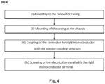
- Figure 4 schematically represents the steps of an assembly method according to a third embodiment of the invention.
- the method of figure 4 illustrates the steps of assembling the charging input electrical connector 1 for a vehicle described above, comprising the charging casing 100, the connector for a rigid monoconductor 200, and the electrical terminals 300.
- the assembly method starts with a step i) of assembling together the connector casing 100.
- step i) the connector casing 100 is assembled such as described in reference to figures 1 and 3 , so as to have the coupling structures 113, 129, on the respective sides 103, 101, and the cavity 123 connecting the sides 101, 103.
- the connector 100 is separate from the connector for a rigid monoconductor 200 and from the electrical terminals 300.
- the connector casing 100 is mounted at a chassis of the vehicle, such that the second side 103 is oriented towards the inside of the chassis, the surface 105 being oriented in the coupling direction.
- the connector casing 100 can be mounted to the chassis by means of the mounting frame 109, fixing holes 109a, and fixing studs 127. The connector casing 100 is thus ready to be coupled with the connector for a rigid monoconductor 200.
- the connector for rigid monoconductor 200 is coupled with the connector casing 100 by moving closer the connector for rigid monoconductor 200, in the direction B opposite the coupling direction A.
- the connector for rigid monoconductor 200 is moved closer to the second coupling structure 113 until the coupling seal 211 of the connector for rigid monoconductor 200 is firmly housed in the interstitial space 119 of the second coupling structure 113.
- the method of the third embodiment comprises a fourth characterising step iv), according to which the electrical terminal 300 is screwed with the rigid monoconductor terminal 209, so as to clamp at least one part of the connector casing 100 between the electrical terminal 300 and the connector for rigid monoconductor 200.
- the electrical terminal 300 is inserted in the cavity 123 of the first side 101 in the coupling direction A, such that the insulating socket 223 is housed in the nut and the respective threads 221, 317 are engaged.
- the screwing comprises a rotation R of the electrical terminal 300 about its axis, first moving closer the electrical terminal 300 in the coupling direction A up to the abutment I2, and then moving closer the connector for rigid monoconductor 200 in the direction B up to the abutment I1.
Landscapes
- Engineering & Computer Science (AREA)
- Manufacturing & Machinery (AREA)
- Power Engineering (AREA)
- Transportation (AREA)
- Mechanical Engineering (AREA)
- Manufacturing Of Electrical Connectors (AREA)
- Details Of Connecting Devices For Male And Female Coupling (AREA)
- Connections By Means Of Piercing Elements, Nuts, Or Screws (AREA)
- Electric Propulsion And Braking For Vehicles (AREA)
- Connector Housings Or Holding Contact Members (AREA)
Abstract
The invention relates to a charging input electrical connector (1) for a vehicle, the electrical connector (1) being configured to receive, in a coupling direction (A), a movable homologous connector of a charging station, the electrical connector (1) comprising a connector casing (100), a connector for a rigid monoconductor (200), and an electrical terminal (300), in particular an electrical terminal (300) configured for electrical currents of at least 100A. The connector (1) is characterised in that the electrical terminal (300) is screwed with a rigid monoconductor terminal (209) of the connector for rigid monoconductor (200), so as to clamp at least one part of the connector casing (100) between the electrical terminal (300) and the connector for rigid monoconductor (200). The invention moreover relates to an electrical terminal for such a vehicle charging input electrical connector, and a method for assembling such a vehicle charging input electrical connector.
Description
- The present invention relates to a charging input electrical connector for a vehicle. The invention also relates to an electrical terminal for such a connector, in particular configured for electrical currents of at least 100A, as well as a method for assembling such a connector.
- It is known in the art to provide, for various types of electric and hybrid vehicles, a charging input electrical connector for charging the battery of said vehicle. Typically, such an electrical connector comprises a connector casing arranged at the chassis of the vehicle and at least one electrical terminal. In particular, the connector is arranged such that a first side is oriented towards the outside of the chassis, and that a second side is oriented towards the inside of the chassis.
- The electrical connector is configured to receive, on the first side, a movable homologous connector, for example a charging gun belonging to a charging station, in order to couple the electrical terminal with a homologous electrical terminal of the movable homologous connector. On the second side, the electrical connector can be electrically linked to the battery by a set of rigid monoconductors, also called "bus-bars". Rigid monoconductors are in particular used for "rapid" battery charging by direct electrical current (DC) with high current intensity, for example, more than 100A.
- More and more, in order to respect the constraints of electrical safety and size, the path of the set of rigid monoconductors through the inside of the chassis of the vehicle increases in complexity and length. This leads to installation, inspection and maintenance difficulties.
- Moreover, it is usual to weld or rivet the ends of the rigid monoconductors to the respective electrical terminals of the electrical connector, fixing the set of rigid monoconductors to the electrical connector. The maintenance difficulties are thus extended to the charging input electrical connector. It can, in particular, become necessary to integrally dismount the set of rigid monoconductors to exchange parts of the electrical connector.
- Given the above, the present invention aims to provide an improved charging input electrical connector, in particular enabling quicker and simpler maintenance operations.
- The aim of the invention is achieved by means of a charging input electrical connector of a vehicle according to the present disclosure. The electrical connector is configured to receive, in a coupling direction, a movable homologous connector of a charging station, and comprises a connector casing, a connector for a rigid monoconductor, and an electrical terminal, in particular an electrical terminal configured for electrical currents of at least 100A.
- The connector casing has a first side and a second side opposite the first side, the connector casing being configured to be arranged at a chassis of the vehicle, such that the second side is oriented towards the inside of the chassis, the first side comprising a first coupling structure configured for a coupling of the connector casing with the homologous connector, and the second side comprising a second coupling structure configured for a coupling of the connector casing with the connector for rigid monoconductor. The connector casing comprises a cavity extending in the coupling direction of the first coupling structure to the second coupling structure, the electrical terminal being arranged in the cavity. The connector for rigid monoconductor comprises a rigid monoconductor terminal.
- The electrical connector is characterised in that the electrical terminal is screwed with the rigid monoconductor terminal so as to clamp at least one part of the connector casing between the electrical terminal and the connector for rigid monoconductor.
- According to this configuration of the inventive electrical connector, the fixing of the electrical terminal to the rigid monoconductor and to the connector casing is obtained by a screwing. In particular, the electrical terminal being arranged in the cavity, it can be screwed on the first side of the casing from the outside of the chassis, through the connector casing, with a terminal of a rigid monoconductor positioned on the second side of the casing, inside the chassis. Thus, the electrical terminal can be exchanged rapidly and effectively, by an unscrewing and screwing operation performed from the outside of the chassis of the vehicle.
- The electrical terminals being subjected to significant mechanical, thermal and electrical stresses during the charging of the battery, degradations of the terminals are more frequent and a replacement is sometimes necessary. The present invention improves the maintenance of the charging input connector by facilitating the exchange of the electrical terminals.
- According to an aspect of the electrical connector, the rigid monoconductor terminal can comprise a screw and the electrical terminal comprises a nut configured to receive the screw, and the electrical terminal is screwed with the rigid monoconductor terminal by screwing the nut on the screw.
- By arranging the electrical terminal with a nut, and the screwed rigid monoconductor terminal, the threads of the screw-nut connection are more protected. Indeed, the exchangeable electrical terminal screwed in the casing of the outside is more likely to incur bumps or other risk-introducing mechanical actions. Thus, the threading of the nut, or inner thread, is associated with the electrical terminal, and the more fragile outer thread is assigned to the rigid monoconductor terminal housed inside the chassis of the second side of the casing.
- The invention also relates to an electrical terminal for a connector according to one of the aspects described below. The electrical terminal is, in particular, configured for electrical currents of at least 100A. The electrical terminal comprises a nut, a first part, and a second part, the first part having a first end of the electrical terminal, and the second part having a second end of the electrical terminal, the second end being opposite the first end, the first part of the electrical terminal being configured to come into contact with a homologous electrical terminal of the homologous electrical connector, and the nut being arranged at the second end. This electrical terminal allows an implementation in the vehicle charging input electrical connector according to the invention, thus achieving the advantages stated.
- The optional technical features and the associated advantages described below can be freely combined one by one or adapted to particular embodiments, insofar as the scope of the invention such as described above is respected. In particular, the optional features of the inventive electrical terminal can also be assigned to the electrical terminal of the charging input electrical connector according to the invention.
- According to an aspect of the invention, the electrical terminal can comprise a first part having a first end of the electrical terminal, and a second part having a second end of the electrical terminal, the second end being opposite the first end, the first part of the electrical terminal being configured to come into contact with a homologous electrical terminal of the homologous electrical connector, the nut being arranged at the second end.
- In this configuration, the electrical terminal can be screwed through the connector casing. In particular, a screwing movement applied at the first end, outside of the chassis, can obtain a screwing with the rigid monoconductor terminal at the second end, inside the chassis.
- According to an aspect of the invention, the electrical terminal is a male electrical terminal configured to be coupled with a female electrical terminal of the movable homologous connector. A male electrical terminal being thinner and lighter than a female terminal, the arrangement, and in particular the maintenance, of the electrical terminal at the vehicle can be facilitated.
- According to an aspect of the invention, the electrical terminal can comprise an insulating tip arranged at the first end. The insulating tip can reduce the risk of electrocution for assemblers and for users of the vehicle at the charging input electrical connector.
- According to an aspect of the invention, the screw of the bus terminal can comprise an insulating socket, in particular arranged at the end of the screw. The socket can reduce the risk of electrocution during the installation of the rigid monoconductor, and increases the workability of the connector for a rigid monoconductor.
- According to an aspect of the invention, the electrical connector can comprise a plurality, in particular two, of said electrical terminals, and the connector for a rigid monoconductor can comprise a number of rigid monoconductor terminals equivalent to the number of electrical terminals. Two electrical terminals can make it possible to close a direct current electrical circuit. A plurality of electrical terminals can increase the transmissible power and the battery charging speed.
- According to an aspect of the invention, the smallest outer diameter of the second part can be larger, in particular between 20% and 200% larger, than the largest outer diameter of the first part. The second part can thus be sufficiently wide to receive the nut. In particular, the second part being responsible for the fixing by screwing of the electrical terminal, the interfacial mechanical forces, for example from twisting, that are applied can be significant, and the larger diameter can enable an improved mechanical stability.
- According to an aspect of the invention, the second part can comprise a projecting part, the projecting part having a larger diameter than the smallest outer diameter of the second part. The projecting part can create an abutment at the second part, the abutment enabling a form-fitting with the connector casing during the assembly by screwing of the electrical terminal with the connector for rigid monoconductor.
- According to an aspect of the invention, the projecting part can project from the second part, at least on the side oriented towards the second end, in a step shape, in particular, perpendicularly. When the projecting part projects in a step shape, the abutment is better demarcated, and thus increases the mechanical stability of a form-fitting.
- According to an aspect of the invention, the at least one part of the clamped casing can comprise a shape complementary to the step shape, the complementary shape projecting into the cavity, so as to establish a connection by form-fitting with the electrical terminal, in particular, such that the connection by form-fitting blocks a movement of the electrical terminal in the coupling direction.
- Thus, the electrical terminal can abut with the connector casing during screwing. In particular, when the electrical terminal is inserted in the cavity and screwed with the rigid monoconductor terminal, the projecting part can abut on the complementary shape of the connector casing, establishing the connection by form-fitting. By screwing and moving the electrical terminal closer to the rigid monoconductor terminal, the at least one part of the connector casing can be clamped between the electrical terminal and the connector for rigid monoconductor.
- According to an aspect of the invention, the projecting part can be arranged in a region for connecting the second part with the first part. The projecting part is thus removed from the nut at the second end and from the first end, and thus less at risk of interfering with the coupling with the rigid monoconductor terminal and/or with the coupling with the homologous connector.
- According to an aspect of the invention, the electrical terminal can comprise a seal disposed at the projecting part, in particular an O-ring disposed along a circumference of the electrical terminal at the projecting part. The seal makes it possible to improve the sealing in the cavity, and thus creates a sealing between the inside and the outside of the vehicle.
- According to an aspect of the invention, the first part comprises a clamping element, in particular a form element configured for the coupling with a clamping tool comprising a complementary form. In particular, the clamping element can be a triangular, pentagonal, heptagonal, or octagonal element centred on an axis of the electrical terminal. The clamping element can make it possible to limit the screwing and unscrewing of the electrical terminal with the rigid monoconductor terminal to the operators having a tool complementary to the clamping element. Thus, the clamping element can serve to facilitate the clamping of the electrical terminal, and at the same time, provide a foolproofing against unintended handling.
- The invention moreover concerns a method for assembling a charging input electrical connector for a vehicle according to one of the aspects described above. The assembly method comprises the steps of a) assembling the connector casing, b) mounting the connector casing at a vehicle chassis, such that the second side is oriented towards the inside of the chassis, c) coupling of the connector for a rigid monoconductor with the second coupling structure, and d) screwing of the electrical terminal with the rigid monoconductor terminal, so as to clamp at least one part of the connector casing between the electrical terminal and the connector for a rigid monoconductor. Such as already described above, this is a quicker, more comfortable and less expensive method than the assembly methods of the prior art.
- The aims, features and advantages of the invention such as outlined above will be more exhaustively understood and appreciated by studying the more detailed description below of an embodiment of the invention, using the accompanying drawings.
-
Figure 1 illustrates a connector casing and a connector for a rigid monoconductor for a charging input electrical connector for a vehicle according to an embodiment of the invention. -
Figure 2 illustrates an electrical terminal according to an embodiment of the invention. -
Figure 3 illustrates a charging input electrical connector for a vehicle according to an embodiment of the invention. -
Figure 4 schematically illustrates the steps of an assembly method according to an embodiment of the invention. - Below, reference signs to identical figures are used to reference elements of the same nature.
- An electrical connector according to a first embodiment of the invention is described below, by referring to
figures 1 to 3 . Theelectrical connector 1 described and illustrated infigures 1 to 3 is a charging input connector of an electric motor vehicle. In this embodiment, theelectrical connector 1 is a connector of a type called CCS (Combined Charging System), specifically a connector of the "CCS Combo 2" or "FF" type, such as defined by the standard IEC 62196. Theelectrical connector 1 therefore comprises a slow charging terminal, in particular called "Type 2", and two electrical terminals for a rapid direct current charge. In alternative embodiments of the invention, the electrical connector can be of the "EE" (or "CCS Combo 1"), "AA", "BB", or "ChaoJi" type, or of any other type which can be compliant with the terms of the invention described above and comprising at least one electrical terminal, in particular an electrical terminal configured for electrical currents of at least 100A. -
Figure 1 illustrates a perspective view of theelectrical connector 1 during assembly. Theelectrical connector 1 comprises aconnector casing 100, a connector forrigid monoconductor 200, and twoelectrical terminals 300. Theelectrical terminals 300 cannot be seen infigure 1 , and will be described in reference tofigure 2 and3 . Theelectrical connector 1 is configured to receive, in the coupling direction A parallel to the Cartesian direction x, the homologous connector of a charging station, i.e. a charging gun of the "FF", or CCS Combo 2 type. - The
connector casing 100 has afirst side 101 and asecond side 103, visible infigure 1 and opposite thefirst side 101 in the coupling direction A. Asurface 105 of thefirst side 101 is oriented against the coupling direction A, and asurface 107 of thesecond side 103 is oriented in the coupling direction A. - On the
first side 101, theconnector casing 100 comprises a mountingframe 109, comprising a plurality of, in particular four, fixingholes 109a to fix theconnector casing 100 to a chassis of the electric vehicle. Theconnector casing 100 is configured to be arranged at the chassis, such that thesecond side 103, and in particular, thesurface 107 are oriented towards the inside of the chassis, i.e. towards the inner space of the vehicle. Correspondingly, theconnector casing 100 is configured to be arranged at the chassis, such that thefirst side 101 and, in particular, thesurface 105 are oriented towards the outside of the chassis, i.e. towards the ambient environment, wherein the vehicle is located. - The
second side 103 comprises, formed on thesurface 107, aninner coupling zone 111 for the slow charging terminal mentioned above, and asecond coupling structure 113. Thesecond coupling structure 113 is configured to facilitate the coupling of theconnector casing 100 with the connector forrigid monoconductor 200, to establish an electrical link with the battery and realize a "rapid" charge. In particular, thesecond coupling structure 113 comprises afirst partition 115, and asecond partition 117 surrounding thefirst partition 115. The first 115 and thesecond partition 117 project from thesurface 107 of thesecond side 103 in the coupling direction A. Theinterstitial space 119 between the first 115 and thesecond partition 117 is configured to receive thefront end part 207 of the connector forrigid monoconductor 200, in which therigid monoconductor terminals 209 are disposed (seefigure 3 ). - Inside the area delimited by the
first partition 115, twoopenings 121 are disposed. Each of theopenings 121 gives access to arespective cavity 123. Thecavities 123 pass through the connector casing from thefirst side 101 to thesecond side 103, extending along the coupling direction A. Eachcavity 123 is configured to receive anelectrical terminal 300 in the coupling direction A, and will be more fully described in reference tofigure 3 . Theconnector casing 100 moreover comprises fixinginputs 125 for an actuator, for example for a locking system with the homologous connector, andelectronic interface structures 127 for signalling connections. - The connector for
rigid monoconductor 200 comprises a connector casing forrigid monoconductor 201, which envelopes the ends of a set of rigid monoconductors. In the present embodiment, the set of rigid monoconductors comprises two rigid monoconductors 400a, 400b, each with a circular cross-section and equipped with an insulation mantle. In variants, the rigid monoconductors can be non-insulated and/or have a rectangular cross-section. - The connector casing for a
rigid monoconductor 201 is substantially L-shaped, or has a 90° angle. Thus, the connector casing comprises an openrear end part 203 which receives the rigid monoconductors 400a, 400b and which is equipped with acap 205. Complementarily, the connector casing for arigid monoconductor 201 comprises an openfront end part 207, wherein therespective terminals 209 of the rigid monoconductors 400a, 400b are disposed (seefigure 3 ). -
Figure 2 illustrates anelectrical terminal 300 for theelectrical connector 1 of the first embodiment. Theelectrical terminal 300 at the same time also itself represents an electrical terminal according to a second embodiment of the invention. Theelectrical terminal 300 is an electrical terminal for a rapid charging terminal of an "FF" or "Combined Combo 2" type connector, and is configured for currents of at least 100A, i.e. the materials chosen for manufacturing theelectrical terminal 300 are adapted to resist the thermal, mechanical and electrical stresses induced by the passage of currents of at least 100A. - The
electrical terminal 300 is a metal integral part having a mainly cylindrical extended shape. In particular, theelectrical terminal 300 comprises, in the coupling direction A, afirst part 301 and asecond part 303. The first 301 and thesecond part 303 are disposed concentrically and connected in a connectingregion 305. Thefirst part 301 has a first diameter D1 and thesecond part 303 has a second diameter D2. The second diameter D2 is between 20% and 200%, preferably between 50% and 70%, larger than the first diameter D1. - The
first part 301 comprises afirst end 307 of theelectrical terminal 300. Thesecond part 303 comprises asecond end 309 of the electrical terminal opposite thefirst end 307. For reasons of workability and electrical safety, theelectrical terminal 300 comprises an insulatingtip 311 mounted on thefirst part 301 at thefirst end 307. - At the
second end 309, theelectrical terminal 300 comprises anut 313. Thenut 313 is disposed in acavity 315 formed coaxially in thesecond part 303. Thenut 313 comprises a threading 317, theelectrical terminal 300 can be screwed on a screw, a bolt or another device comprising an outer thread complementary to thethreading 317. - The
first part 301 comprises, at the connectingregion 305, aclamping element 319. In this embodiment, the clampingelement 319 is a local deformation of the circular cross-section of thefirst part 301, capable of supporting clamping torques. In this embodiment, the circular cross-section of thefirst part 301 is deformed towards an enlarged pentagonal cross-section P to form theclamping element 319. The clampingelement 319 serves to facilitate the screwing and the unscrewing of theelectrical terminal 300 by means of a dedicated clamping tool. For example, the dedicated clamping tool can be slipped over thefirst part 301 in the coupling direction A, in order to engage the pentagonal shape of theclamping element 319 with a complementary pentagonal shape of the tool. - The
second part 303 of theelectrical terminal 301 comprises a projectingpart 321, also cylindrical, arranged at the connectingregion 305 and projecting from thesecond part 303. The projectingpart 321 projects perpendicularly to the coupling direction A. Thus, the projectingpart 321 forms astep shape 323. The projectingpart 321 has a larger diameter D3, in particular between 2% and 10% larger, than the diameter D2 of thesecond part 303. An O-ring 325 is disposed along a circumference of the cylindricalouter surface 327 of the projectingpart 321. -
Figure 3 illustrates a transverse view of theelectrical connector 1 in a final assembly state. The transverse view offigure 3 corresponds to a transverse view along the cross-section line C such as indicated infigure 1 , after the coupling of the connector for arigid monoconductor 200 with thesecond coupling structure 113. In particular, the connector for arigid monoconductor 200 is moved closer, in the direction B opposite the coupling direction A, towards thesecond side 103 of theconnector casing 100, until thefront end part 207 is coupled with thesecond coupling structure 113. - The transverse view of
figure 3 shows that thefront end part 207 comprises acoupling seal 211 making it possible to seal the coupling when thefront end part 207 is inserted in theinterstitial space 119 between thepartitions second coupling structure 113. Arear seal 213 allows a sealing of the opening of therear end part 203 which is closed by thecap 205. -
Figure 3 shows that the connector casing forrigid monoconductor 201 envelopes aninner casing 215 housing therigid monoconductor terminals 209 of the respective rigid monoconductors 400a, 400b. The tworespective terminals 209 of the rigid monoconductors 400a, 400b are identical, and only one will be described below. - The terminal 209 corresponds to a flattened
end 401b (and/or 401a) of arigid monoconductor 400b (respectively 400a), wherein ahole 217 has been formed, thehole 217 passing through saidend 401b in the coupling direction A. The terminal 209 comprises ascrew 219, inserted in thehole 217 in the direction B opposite the coupling direction A, and welded to theend 401b of therigid monoconductor 400b, at theabutment interface 11. Thescrew 219 comprises a threadedpart 221 configured to be coupled with the threading 317 of thenut 313. Thescrew 219 also comprises an insulatingsocket 223 to increase the workability and electrical safety of the connector forrigid monoconductor 200. - The transverse view of
figure 3 shows that thecavities 123 extend through theconnector casing 100, along the coupling direction. In particular, thecavities 123 extend from afirst coupling structure 129 arranged on thefirst side 101, to thesecond coupling structure 113. Thefirst coupling structure 129 comprises, on the first side and correspondingly to thesecond coupling structure 113, afirst partition 131, and asecond partition 133 surrounding thefirst partition 131. Theinterstitial space 135 between the twopartitions figure 3 shows that thefirst side 131 comprises, correspondingly to thesecond side 103, anouter coupling zone 137 for the slow recharging terminal. - In the final state illustrated in
figure 3 , theelectrical terminals 300 are arranged in therespective cavities 123. In particular, theelectrical terminals 300 are inserted in the coupling direction A, then screwed with therespective screws 219 of therigid monoconductor terminals 209. In particular, theelectrical terminals 300 are screwed in the direction of rotation R, moving progressively closer theelectrical terminals 300 in the coupling direction A and the connector forrigid monoconductor 200 in the direction B opposite the coupling direction A. - The movement in the coupling direction A of the
electrical terminals 300 is blocked by theprojection 139 projecting into thecavity 123. Theprojection 139 projects into thecavity 123 with a step shape141 complementary to the step shape323 of the projectingpart 321 of theelectrical terminal 300. Thus, the step shape141 of theprojection 139 of thecasing 100 and the step shape323 of the projectingpart 321 of theelectrical terminal 300 abut at the interface I2 during the screwing of theelectrical terminal 300 with therigid monoconductor terminal 209, forming a connection by form-fitting blocking the movement of theelectrical terminal 300 in thecavity 123 in the coupling direction A. - A continuation of the screwing movement in the direction of rotation R thus moves closer the connector for
rigid monoconductor 200 in the direction B, until the abutment I3 of thesecond end 309 of theelectrical terminal 300 on theend 401a (or 401b) of the rigid monoconductor 400a (respectively 400b). Thus, the screwing of theelectrical terminal 300 with the rigid monoconductor terminal 209 clamps theconnector casing 100 between theelectrical terminal 300 and the connector forrigid monoconductor 200. In particular, the screwing of theelectrical terminal 300 with the rigid monoconductor terminal 209 clamps the part P of theconnector casing 100 between the interface I2 on one hand, and the interface I4 between the connector for rigid monoconductor 200 and thesurface 107 on the other hand. - The O-
ring 325 ensures the sealing of the arrangement of theelectrical terminal 300 and theconnector casing 100, in particular between the outside and the inside of the chassis. At the step shapes323, 141, theelectrical terminal 300 and theconnector casing 100 are in contact or in immediate proximity. These regions are thus suitable for the placement, in theconnector casing 100, of elements for monitoring or for measuring theelectrical terminal 300, such as temperature sensors of theelectrical terminal 300. - The
electrical terminal 300 is screwed from thefirst side 101 of thecasing 100, from the outside of the chassis, through theconnector casing 100, with therigid monoconductor terminal 209 localised on the second side of thecasing 203, inside the chassis. Theelectrical terminal 300 can thus be exchanged rapidly and effectively, by an unscrewing and screwing operation performed outside of the chassis of the vehicle. In particular, it is not necessary to open, change, or handle theconnector casing 100, and it is not necessary, in particular, to access therigid monoconductor terminal 209 inside the chassis or to handle the rigid monoconductors 400a, 400b. - The
electrical connector 1 according to the invention moreover has an increased electrical performance, with respect to the solutions of the prior art, such as ultrasonic welding or riveting, of the electrical terminals with the rigid monoconductors. Indeed, welding and riveting generally require the interposition of a metal square or of another intermediate conductive part between the electrical terminal and the rigid monoconductor terminal. The interposition of intermediate parts creates contact interfaces which increase the electrical resistance of the circuit, and thus cause heat losses. At the same time, the omission of the intermediate part makes the assembly quicker and less expensive. - The separability of the
electrical terminals 300 from the rigid monoconductors 400a, 400b and from theconnector casing 100 also enables a greater flexibility in the assembly of the vehicle. Theconnector casing 100, which typically is particularly heavy, and the rigid monoconductors 400a, 400b can be assembled and mounted at the chassis of the vehicle independently, in a chosen order. -
Figure 4 schematically represents the steps of an assembly method according to a third embodiment of the invention. The method offigure 4 illustrates the steps of assembling the charging inputelectrical connector 1 for a vehicle described above, comprising the chargingcasing 100, the connector for arigid monoconductor 200, and theelectrical terminals 300. - Such as illustrated in
figure 4 , the assembly method starts with a step i) of assembling together theconnector casing 100. In step i), theconnector casing 100 is assembled such as described in reference tofigures 1 and3 , so as to have thecoupling structures respective sides cavity 123 connecting thesides connector 100 is separate from the connector for arigid monoconductor 200 and from theelectrical terminals 300. - In a second step ii), the
connector casing 100 is mounted at a chassis of the vehicle, such that thesecond side 103 is oriented towards the inside of the chassis, thesurface 105 being oriented in the coupling direction. For example, theconnector casing 100 can be mounted to the chassis by means of the mountingframe 109, fixingholes 109a, and fixingstuds 127. Theconnector casing 100 is thus ready to be coupled with the connector for arigid monoconductor 200. - Thus, in a third step iii), the connector for
rigid monoconductor 200 is coupled with theconnector casing 100 by moving closer the connector forrigid monoconductor 200, in the direction B opposite the coupling direction A. The connector forrigid monoconductor 200 is moved closer to thesecond coupling structure 113 until thecoupling seal 211 of the connector forrigid monoconductor 200 is firmly housed in theinterstitial space 119 of thesecond coupling structure 113. - The method of the third embodiment comprises a fourth characterising step iv), according to which the
electrical terminal 300 is screwed with therigid monoconductor terminal 209, so as to clamp at least one part of theconnector casing 100 between theelectrical terminal 300 and the connector forrigid monoconductor 200. In particular, theelectrical terminal 300 is inserted in thecavity 123 of thefirst side 101 in the coupling direction A, such that the insulatingsocket 223 is housed in the nut and therespective threads electrical terminal 300 about its axis, first moving closer theelectrical terminal 300 in the coupling direction A up to the abutment I2, and then moving closer the connector forrigid monoconductor 200 in the direction B up to the abutment I1. This method enables a particularly rapid and flexible assembly of a vehicle charging input electrical connector, and in particular, offers the advantages obtained by the implementation of theconnector 1, in particular a maintenance facilitated by exchangeableelectrical terminals 300. -
- 1 vehicle charging input electrical connector
- 100 connector casing
- 101 first side
- 103 second side
- 105 surface on first side
- 107 surface of the second side
- 109 mounting frame
- 109a fixing holes
- 111 inner coupling zone for the slow recharging terminal
- 113 second coupling structure
- 115 first partition (second structure)
- 117 second partition (second structure)
- 119 interstitial space between partitions (second structure)
- 121 opening to the cavity
- 123 cavity
- 125 actuator fixing inputs
- 127 electronic interface structures
- 129 first coupling structure
- 131 first partition (first structure)
- 133 second partition (first structure)
- 135 interstitial space between partitions (first structure)
- 137 outer coupling zone for the slow recharging terminal
- 139 projection into the cavity
- 141 step shape
- 200 connector for rigid monoconductor
- 201 connector casing for rigid monoconductor
- 203 rear end part
- 205 cap
- 207 front end part
- 209 rigid monoconductor terminal
- 211 coupling seal
- 213 rear seal
- 215 inner casing
- 217 hole in the terminal
- 219 screw of the terminal
- 221 threaded part of the screw
- 223 insulating socket
- 300 electrical terminal
- 301 first part
- 303 second part
- 305 connecting region
- 307 first end
- 309 second end
- 311 insulating tip
- 313 nut
- 315 cavity housing the nut
- 317 threading of the nut
- 319 clamping element
- 321 projecting part
- 323 step shape325 seal
- 327 outer surface of the projecting part
- 400a, 400b rigid monoconductor
- A coupling direction
- D1 outer diameter of the first part
- D2 outer diameter of the second part
- D3 diameter of the projecting part
- P pentagonal cross-section
- I1 welding interface between the rigid monoconductor end and the screw
- I2 abutment between the electrical terminal and the connector casing
- I3 abutment between the electrical terminal and the connector for rigid monoconductor
- I4 interface between the connector for rigid monoconductor and the connector casing
- P clamped part R direction of rotation of screwing
- x,y,z Cartesian directions
Claims (10)
- Charging input electrical connector (1) for a vehicle, the electrical connector (1) being configured to receive, in a coupling direction (A), a movable homologous connector of a charging station,the electrical connector (1) comprising a connector casing (100), a connector for rigid monoconductor (200), and an electrical terminal (300), in particular an electrical terminal (300) configured for electrical currents of at least 100A,the connector casing (100) having a first side (101) and a second side (103) opposite the first side (101), the connector casing (100) being configured to be arranged at a chassis of the vehicle, such that the second side (103) is oriented towards the inside of the chassis,the first side (101) comprising a first coupling structure (129) configured for a coupling of the connector casing (100) with the homologous connector, and the second side (103) comprising a second coupling structure (113) configured for a coupling of the connector casing (100) with the connector for a rigid monoconductor (200),the connector casing (100) comprising a cavity (123) extending in the coupling direction (A) from the first coupling structure (129) to the second coupling structure (113), the electrical terminal (300) being arranged in the cavity (123),the connector for rigid monoconductor (200) comprising a rigid monoconductor terminal (209),characterised in that the electrical terminal (300) is screwed with the rigid monoconductor terminal (209) so as to clamp at least one part of the connector casing (100) between the electrical terminal (300) and the connector for rigid monoconductor (200).
- Electrical connector according to claim 1, wherein the rigid monoconductor terminal (209) comprises a screw (219) and the electrical terminal (300) comprises a nut (313) configured to receive the screw (219), and the electrical terminal (300) is screwed with the rigid monoconductor terminal (209) by screwing the nut (313) on the screw (219).
- Electrical connector according to claim 2, whereinthe electrical terminal (300) comprises a first part (301) having a first end (307) of the electrical terminal (300), and a second part (303) having a second end (309) of the electrical terminal (300), the second end (309) being opposite the first end (307),the first part (301) of the electrical terminal (300) being configured to come into contact with a homologous electrical terminal of the homologous electrical connector,the nut (313) being arranged at the second end (309).
- Connector according to claim 3, wherein the smallest outer diameter (D2) of the second part (303) is larger, in particular between 20% and 200% larger, than the largest outer diameter (D1) of the first part (301).
- Connector according to claim 4, wherein the second part (303) comprises a projecting part (321), the projecting part (321) having a larger diameter (D3), in particular between 2% and 10% larger, than the smallest outer diameter (D2) of the second part (303).
- Connector according to claim 5, wherein the projecting part (321) projects from the second part (303), at least on the side oriented towards the second end (309), in step shape (323), in particular, perpendicularly.
- Connector according to claim 5 or 6, wherein the at least one part of the clamped connector casing (100) comprises a shape (141) complementary to the step shape (323), the complementary shape (141) projecting into the cavity (123) so as to establish a connection by form-fitting with the electrical terminal (300), in particular, such that the connection by form-fitting blocks a movement of the electrical terminal (300) in the coupling direction (A).
- Connector according to one of claims 5 to 7, wherein the projecting part (321) is arranged in a region (305) for connecting the second part (303) with the first part (301).
- Electrical terminal for a connector according to one of claims 1 to 8, in particular configured for electrical currents of at least 100A, the electrical terminal (300) comprising a nut (313), a first part (301), and a second part (303),the first part (301) having a first end (307) of the electrical terminal (300), and the second part (303) having a second end (309) of the electrical terminal (300), the second end (309) being opposite the first end (307),the first part (301) of the electrical terminal (300) being configured to come into contact with a homologous electrical terminal of the homologous electrical connector, andthe nut (313) being arranged at the second end (209).
- Method for assembling a charging input electrical connector (1) for a vehicle according to one of claims 1 to 8, comprising the steps ofa) assembling the connector casing (100),b) mounting the connector casing (100) at the chassis of the vehicle, such that the second side (103) is oriented towards the inside of the chassis,c) coupling the connector for rigid monoconductor (200) with the second coupling structure (113), andd) screwing the electrical terminal (300) with the rigid monoconductor terminal (209), so as to clamp at least one part of the connector casing (100) between the electrical terminal (300) and the connector for rigid monoconductor (200).
Applications Claiming Priority (1)
| Application Number | Priority Date | Filing Date | Title |
|---|---|---|---|
| FR2302316A FR3146623A1 (en) | 2023-03-13 | 2023-03-13 | Vehicle charging input electrical connector |
Publications (1)
| Publication Number | Publication Date |
|---|---|
| EP4439868A1 true EP4439868A1 (en) | 2024-10-02 |
Family
ID=87280592
Family Applications (1)
| Application Number | Title | Priority Date | Filing Date |
|---|---|---|---|
| EP24163294.2A Pending EP4439868A1 (en) | 2023-03-13 | 2024-03-13 | Charging input electrical connector for a vehicle |
Country Status (6)
| Country | Link |
|---|---|
| US (1) | US20240308362A1 (en) |
| EP (1) | EP4439868A1 (en) |
| JP (1) | JP7846153B2 (en) |
| KR (1) | KR20240139001A (en) |
| CN (1) | CN118645831A (en) |
| FR (1) | FR3146623A1 (en) |
Cited By (1)
| Publication number | Priority date | Publication date | Assignee | Title |
|---|---|---|---|---|
| DE102024134298A1 (en) * | 2024-11-21 | 2026-05-21 | Amphenol Tuchel Industrial GmbH | Contact arrangement for charging plug |
Citations (3)
| Publication number | Priority date | Publication date | Assignee | Title |
|---|---|---|---|---|
| EP3331099A1 (en) * | 2015-12-25 | 2018-06-06 | Fujikura Ltd. | Charging connector and charging connector assembly production method |
| US20200052452A1 (en) * | 2016-10-26 | 2020-02-13 | Rosenberger Hochfrequenztechnik Gmbh & Co. Kg | Assembly method for a connector |
| EP4210176A1 (en) * | 2022-01-10 | 2023-07-12 | HARTING Automotive GmbH | Method for producing an inlet, inlet and multicontact plug |
Family Cites Families (21)
| Publication number | Priority date | Publication date | Assignee | Title |
|---|---|---|---|---|
| JP3070440B2 (en) | 1995-04-20 | 2000-07-31 | 住友電装株式会社 | Waterproof electrode |
| JP5312214B2 (en) * | 2009-06-11 | 2013-10-09 | 矢崎総業株式会社 | Lever-type electrical connector with misoperation prevention |
| FR2953071B1 (en) * | 2009-11-23 | 2012-04-20 | Tyco Electronics France Sas | ELECTRICAL CONNECTOR HOUSING |
| JP5559635B2 (en) * | 2010-08-09 | 2014-07-23 | タイコエレクトロニクスジャパン合同会社 | Waterproof electrical connector, assembling method of waterproof electrical connector |
| JP2013084429A (en) | 2011-10-07 | 2013-05-09 | Auto Network Gijutsu Kenkyusho:Kk | connector |
| FR3050078B1 (en) * | 2016-04-11 | 2019-11-08 | Tyco Electronics France Sas | PYROTECHNIC CONNECTOR |
| FR3079032B1 (en) * | 2018-03-19 | 2020-09-04 | Tyco Electronics France Sas | Electrical box and method for testing the tightness of the electrical box |
| US10651586B2 (en) * | 2018-06-01 | 2020-05-12 | Tyco Electronics Brasil Ltda | Electrical connector with machine-readable graphic identifier |
| JP7087961B2 (en) | 2018-11-28 | 2022-06-21 | 住友電装株式会社 | Vehicle connector |
| FR3101203B1 (en) * | 2019-09-20 | 2023-04-07 | Tyco Electronics France Sas | Housing for a vehicle charging device |
| KR102807982B1 (en) | 2019-11-27 | 2025-05-14 | 엘에스이브이코리아 주식회사 | Electric Vehicle Charging Connector and Electric Vehicle Charging Assembly |
| DE102020126962B4 (en) * | 2020-01-21 | 2026-01-29 | Hanon Systems | Arrangement for connecting electrical terminals and device for driving a compressor with the arrangement |
| TWI733369B (en) * | 2020-03-12 | 2021-07-11 | 連展科技股份有限公司 | Power terminal wire-connection device and method thereof |
| US20210347270A1 (en) | 2020-07-20 | 2021-11-11 | Yazaki North America, Inc. | Transient heat storage for dc charge inlet connector assembly |
| JP7204310B2 (en) | 2020-10-19 | 2023-01-16 | 矢崎総業株式会社 | Connector and connector with electric wire provided with the connector |
| DE102021101528A1 (en) * | 2021-01-25 | 2022-07-28 | Phoenix Contact E-Mobility Gmbh | High current module for charging connector part |
| EP4059767A1 (en) * | 2021-03-17 | 2022-09-21 | ABB Schweiz AG | Charging connector for an electric vehicle |
| FR3125175B1 (en) * | 2021-07-06 | 2023-12-15 | Tyco Electronics France Sas | Waterproof cable gland of a pluggable connector |
| CN113725652A (en) | 2021-08-06 | 2021-11-30 | 长春捷翼汽车零部件有限公司 | Charging seat and automobile |
| US12668138B2 (en) * | 2021-09-10 | 2026-06-30 | Aptiv Technologies AG | Serviceable power inlet connector |
| CN116315814A (en) * | 2021-12-06 | 2023-06-23 | Abb电动汽车有限责任公司 | Electric Vehicle Charging Connector |
-
2023
- 2023-03-13 FR FR2302316A patent/FR3146623A1/en active Pending
-
2024
- 2024-03-08 KR KR1020240033331A patent/KR20240139001A/en active Pending
- 2024-03-11 JP JP2024036564A patent/JP7846153B2/en active Active
- 2024-03-12 CN CN202410277905.7A patent/CN118645831A/en active Pending
- 2024-03-12 US US18/602,320 patent/US20240308362A1/en active Pending
- 2024-03-13 EP EP24163294.2A patent/EP4439868A1/en active Pending
Patent Citations (3)
| Publication number | Priority date | Publication date | Assignee | Title |
|---|---|---|---|---|
| EP3331099A1 (en) * | 2015-12-25 | 2018-06-06 | Fujikura Ltd. | Charging connector and charging connector assembly production method |
| US20200052452A1 (en) * | 2016-10-26 | 2020-02-13 | Rosenberger Hochfrequenztechnik Gmbh & Co. Kg | Assembly method for a connector |
| EP4210176A1 (en) * | 2022-01-10 | 2023-07-12 | HARTING Automotive GmbH | Method for producing an inlet, inlet and multicontact plug |
Cited By (1)
| Publication number | Priority date | Publication date | Assignee | Title |
|---|---|---|---|---|
| DE102024134298A1 (en) * | 2024-11-21 | 2026-05-21 | Amphenol Tuchel Industrial GmbH | Contact arrangement for charging plug |
Also Published As
| Publication number | Publication date |
|---|---|
| US20240308362A1 (en) | 2024-09-19 |
| JP7846153B2 (en) | 2026-04-14 |
| FR3146623A1 (en) | 2024-09-20 |
| CN118645831A (en) | 2024-09-13 |
| JP2024129812A (en) | 2024-09-27 |
| KR20240139001A (en) | 2024-09-20 |
Similar Documents
| Publication | Publication Date | Title |
|---|---|---|
| KR102763165B1 (en) | Contact assembly with a frictionally mated contact element as well as module connector, connection assembly, battery cell and battery module with such contact assemblies | |
| US11303073B2 (en) | Charging inlet assembly | |
| US8440918B2 (en) | Assembly of case and electronic components and combination of the assembly and external connectors | |
| JP7740844B2 (en) | Electrical High Current Connector | |
| WO2013080780A1 (en) | Connector and wire harness | |
| CN103339761A (en) | battery connection assembly | |
| JP2011503788A (en) | Plug and plug connection for robots | |
| CN114079195B (en) | Electric vehicle charging connector | |
| US20240308362A1 (en) | Charging input electrical connector for a vehicle | |
| US20240351457A1 (en) | Charging inlet assembly of a vehicle | |
| US20240424925A1 (en) | Charging terminal for a charging inlet assembly of a vehicle | |
| KR101136806B1 (en) | Electrode Terminal Connecting Device and Battery Module Assembly Employed with the Same | |
| CN115842260A (en) | High-voltage connector suitable for copper-aluminum connection | |
| JP2015521352A (en) | Interconnect assembly comprising electrical devices and wires, and interconnect method | |
| JP5737046B2 (en) | Battery wiring module | |
| CN114927832A (en) | Battery system, module connector and method for replacing a defective battery cell module in a battery system | |
| EP4496139B1 (en) | Connector assembly and method of assembling such a connector assembly | |
| US12479318B2 (en) | Charging inlet assembly having a power harness | |
| CN217607410U (en) | Junction box and vehicle | |
| WO2024222855A1 (en) | Hard wiring harness connector | |
| CN118156922A (en) | Electrical connector arrangement, electrical mating conductor, and electrical assembly having the electrical mating conductor | |
| CN215008125U (en) | Fuse subassembly, coupling assembling, connecting device, distribution equipment and vehicle | |
| CN209344438U (en) | A kind of high-tension connector | |
| US20240208340A1 (en) | Charge inlet | |
| US20260094991A1 (en) | Sealed electrical connector including a sealing wall and trunnions |
Legal Events
| Date | Code | Title | Description |
|---|---|---|---|
| PUAI | Public reference made under article 153(3) epc to a published international application that has entered the european phase |
Free format text: ORIGINAL CODE: 0009012 |
|
| STAA | Information on the status of an ep patent application or granted ep patent |
Free format text: STATUS: THE APPLICATION HAS BEEN PUBLISHED |
|
| AK | Designated contracting states |
Kind code of ref document: A1 Designated state(s): AL AT BE BG CH CY CZ DE DK EE ES FI FR GB GR HR HU IE IS IT LI LT LU LV MC ME MK MT NL NO PL PT RO RS SE SI SK SM TR |
|
| RAP1 | Party data changed (applicant data changed or rights of an application transferred) |
Owner name: TE CONNECTIVITY SOLUTIONS GMBH |
|
| STAA | Information on the status of an ep patent application or granted ep patent |
Free format text: STATUS: REQUEST FOR EXAMINATION WAS MADE |
|
| 17P | Request for examination filed |
Effective date: 20250331 |