EP4439776A1 - Pouch cell deformation inspection device and deformation inspection method using same - Google Patents
Pouch cell deformation inspection device and deformation inspection method using same Download PDFInfo
- Publication number
- EP4439776A1 EP4439776A1 EP23868394.0A EP23868394A EP4439776A1 EP 4439776 A1 EP4439776 A1 EP 4439776A1 EP 23868394 A EP23868394 A EP 23868394A EP 4439776 A1 EP4439776 A1 EP 4439776A1
- Authority
- EP
- European Patent Office
- Prior art keywords
- pouch cell
- hollow receiving
- receiving portion
- deformation testing
- dog
- Prior art date
- Legal status (The legal status is an assumption and is not a legal conclusion. Google has not performed a legal analysis and makes no representation as to the accuracy of the status listed.)
- Pending
Links
Images







Classifications
-
- G—PHYSICS
- G01—MEASURING; TESTING
- G01B—MEASURING LENGTH, THICKNESS OR SIMILAR LINEAR DIMENSIONS; MEASURING ANGLES; MEASURING AREAS; MEASURING IRREGULARITIES OF SURFACES OR CONTOURS
- G01B5/00—Measuring arrangements characterised by the use of mechanical techniques
- G01B5/30—Measuring arrangements characterised by the use of mechanical techniques for measuring the deformation in a solid, e.g. mechanical strain gauge
-
- G—PHYSICS
- G01—MEASURING; TESTING
- G01B—MEASURING LENGTH, THICKNESS OR SIMILAR LINEAR DIMENSIONS; MEASURING ANGLES; MEASURING AREAS; MEASURING IRREGULARITIES OF SURFACES OR CONTOURS
- G01B11/00—Measuring arrangements characterised by the use of optical techniques
- G01B11/24—Measuring arrangements characterised by the use of optical techniques for measuring contours or curvatures
- G01B11/245—Measuring arrangements characterised by the use of optical techniques for measuring contours or curvatures using a plurality of fixed, simultaneously operating transducers
-
- G—PHYSICS
- G01—MEASURING; TESTING
- G01B—MEASURING LENGTH, THICKNESS OR SIMILAR LINEAR DIMENSIONS; MEASURING ANGLES; MEASURING AREAS; MEASURING IRREGULARITIES OF SURFACES OR CONTOURS
- G01B11/00—Measuring arrangements characterised by the use of optical techniques
- G01B11/30—Measuring arrangements characterised by the use of optical techniques for measuring roughness or irregularity of surfaces
- G01B11/306—Measuring arrangements characterised by the use of optical techniques for measuring roughness or irregularity of surfaces for measuring evenness
-
- G—PHYSICS
- G01—MEASURING; TESTING
- G01B—MEASURING LENGTH, THICKNESS OR SIMILAR LINEAR DIMENSIONS; MEASURING ANGLES; MEASURING AREAS; MEASURING IRREGULARITIES OF SURFACES OR CONTOURS
- G01B5/00—Measuring arrangements characterised by the use of mechanical techniques
- G01B5/20—Measuring arrangements characterised by the use of mechanical techniques for measuring contours or curvatures
- G01B5/207—Measuring arrangements characterised by the use of mechanical techniques for measuring contours or curvatures using a plurality of fixed, simultaneously operating transducers
-
- G—PHYSICS
- G01—MEASURING; TESTING
- G01B—MEASURING LENGTH, THICKNESS OR SIMILAR LINEAR DIMENSIONS; MEASURING ANGLES; MEASURING AREAS; MEASURING IRREGULARITIES OF SURFACES OR CONTOURS
- G01B5/00—Measuring arrangements characterised by the use of mechanical techniques
- G01B5/28—Measuring arrangements characterised by the use of mechanical techniques for measuring roughness or irregularity of surfaces
- G01B5/285—Measuring arrangements characterised by the use of mechanical techniques for measuring roughness or irregularity of surfaces for controlling eveness
-
- H—ELECTRICITY
- H01—ELECTRIC ELEMENTS
- H01M—PROCESSES OR MEANS, e.g. BATTERIES, FOR THE DIRECT CONVERSION OF CHEMICAL ENERGY INTO ELECTRICAL ENERGY
- H01M10/00—Secondary cells; Manufacture thereof
- H01M10/42—Methods or arrangements for servicing or maintenance of secondary cells or secondary half-cells
-
- H—ELECTRICITY
- H01—ELECTRIC ELEMENTS
- H01M—PROCESSES OR MEANS, e.g. BATTERIES, FOR THE DIRECT CONVERSION OF CHEMICAL ENERGY INTO ELECTRICAL ENERGY
- H01M10/00—Secondary cells; Manufacture thereof
- H01M10/42—Methods or arrangements for servicing or maintenance of secondary cells or secondary half-cells
- H01M10/4285—Testing apparatus
-
- H—ELECTRICITY
- H01—ELECTRIC ELEMENTS
- H01M—PROCESSES OR MEANS, e.g. BATTERIES, FOR THE DIRECT CONVERSION OF CHEMICAL ENERGY INTO ELECTRICAL ENERGY
- H01M50/00—Constructional details or processes of manufacture of the non-active parts of electrochemical cells other than fuel cells, e.g. hybrid cells
- H01M50/10—Primary casings; Jackets or wrappings
- H01M50/102—Primary casings; Jackets or wrappings characterised by their shape or physical structure
- H01M50/105—Pouches or flexible bags
Definitions
- the present invention relates to a pouch cell deformation testing apparatus and a pouch cell deformation testing method using the same, and more particularly to a pouch cell deformation testing apparatus capable of measuring whether a bending phenomenon has occurred in a pouch cell during an activation process or after the activation process and a pouch cell deformation testing method using the same.
- Secondary batteries which are capable of being charged and discharged, are intimately used in daily life.
- secondary batteries are used in mobile devices, electric vehicles, and hybrid electric vehicles.
- secondary batteries are classified into a cylindrical secondary battery, a prismatic secondary battery, and a pouch-shaped secondary battery.
- the pouch-shaped secondary battery is gradually increasing in use because it is possible to obtain high-capacity, high-density secondary batteries, to reduce manufacturing cost, to reduce weight, and to provide various shapes.
- the pouch-shaped secondary battery is manufactured by laminating a lower separator, a negative electrode, an upper separator, and a positive electrode in that order, applying heat and pressure thereto through a roll lamination process, and stacking dozens of monocells obtained by cutting.
- a bending phenomenon in which an electrode assembly obtained by lamination is bent in an overall width direction may occur due to various reasons.
- the difference in adhesion between the electrode and the separator in the cell may be generated, whereby the bending phenomenon may occur.
- bent secondary batteries are at risk of colliding with equipment during transportation to a subsequent process, such as packaging, or ignition due to falling, a series of testing processes to identify deformed secondary batteries is essential.
- Patent Document 1 discloses an apparatus for testing the deformation of a battery container. That is, a pair of pressing plates 2 connected to driven shafts 1 that may be located at opposite side surfaces of a prismatic battery container 10 is provided, and the pressing plates 2 are brought into tight contact with the surface of the battery container 10 to measure the thickness of the deformed battery container 10.
- Patent Document 1 Japanese Patent Application Publication No. 2014-165059
- the present invention has been made in view of the above problems, and it is an object of the present invention to provide a pouch cell deformation testing apparatus capable of testing deformation of a pouch cell that is easy to change in external shape and a testing method using the same.
- a pouch cell deformation testing apparatus to accomplish the above objects includes a die unit (100) configured to allow a pouch cell (S) to be seated thereon in an erected state and a measurement member (200) located above the die unit (100), the measurement member being configured to measure a flatness of the pouch cell (S).
- the measurement member (200) may be located at a side surface of the pouch cell (S) .
- a plurality of measurement members (200) may be provided in an overall length direction of the pouch cell (S).
- the measurement member (200) may include a hollow receiving portion (210) having a viewing window (211), a moving bar (220) received in the hollow receiving portion (210), a dog (230) mounted to the moving bar (220), a spring (240) received in the hollow receiving portion (210), one end of the spring being fixed to the hollow receiving portion (210), an other end of the spring being connected to one end of the moving bar (220), and a first sensing portion (250) located in a vicinity of the hollow receiving portion (210), wherein the dog (230) may be exposed to the outside through the viewing window (211), wherein a contact portion (222) protruding out of the hollow receiving portion (210) may be provided at an other end of the moving bar (220), and wherein the first sensing portion (250) may detect the dog (230) only when the dog is exposed to the outside through the viewing window (211) .
- the contact portion (222) may be made of an elastic material and may be conical in shape.
- the pouch cell deformation testing apparatus may further include a driving unit (300) configured to move the hollow receiving portion (210) forwards toward the side surface of the pouch cell (S) or rearwards, wherein the driving unit (300) may include a first fixing bar (310) located vertically and fastened to the measurement member (200), a second fixing bar (320) fastened to one side of the first fixing bar (310) and located parallel to the measurement member (200), a guide rail (330) configured to provide the movement path of the second fixing bar (320), and a linear motion member (340) configured to reciprocate the second fixing bar (320) in a straight line by a set distance.
- the driving unit (300) may include a first fixing bar (310) located vertically and fastened to the measurement member (200), a second fixing bar (320) fastened to one side of the first fixing bar (310) and located parallel to the measurement member (200), a guide rail (330) configured to provide the movement path of the second fixing bar (320), and a linear motion member (340) configured to reciprocate the second fixing bar
- the hollow receiving portion (210) may include a plurality of hollow receiving portions spaced apart from each other by a certain distance in an overall width direction of the pouch cell (S), and the first fixing bar (310) may be fastened to the plurality of hollow receiving portions (210).
- the hollow receiving portions (210) may be located at a lower edge, at an upper edge, and between the lower edge and the upper edge of the pouch cell (S) in the overall width direction of the pouch cell (S).
- the hollow receiving portions (210) may be located at one side edge, at an other side edge, and between the one side edge and the other side edge of the pouch cell (S) in the overall length direction.
- the measurement member (200) may include a hollow receiving portion (210) and a second sensing portion (260) received in the hollow receiving portion (210), and the second sensing portion (260) may be provided with a second sensor (261) configured to measure the distance to the pouch cell (S) in a non-contact manner.
- a pouch cell deformation testing method includes a first step of locating a pouch cell (S) disposed vertically and a second step of determining whether the pouch cell (S) is normal based on a flatness of the pouch cell (S) using a measurement member (200) located at a side surface of the pouch cell, wherein the measurement member (200) measures the flatness of the pouch cell (S) in a contact manner or a non-contact manner.
- the measurement member (200) may include a hollow receiving portion (210) having a viewing window (211), a moving bar (220) received in the hollow receiving portion (210), a dog (230) mounted to the moving bar (220), a spring (240) received in the hollow receiving portion (210), one end of the spring being fixed to the hollow receiving portion (210), an other end of the spring being connected to one end of the moving bar (220), and a first sensing portion (250) located in a vicinity of the hollow receiving portion (210), and in the second step, the hollow receiving portion (210) is moved toward the side surface of the pouch cell (S) until the hollow receiving portion reaches a set position, in the state in which the hollow receiving portion is located orthogonal to the side surface of the pouch cell (S), when the dog (230) is exposed to the outside through the viewing window (211) and the first sensing portion (250) detects the dog (230), the pouch cell may be determined to be normal, and when the first sensing portion does not
- a plurality of measurement members (200) may be provided at one side surface or opposite side surfaces of the pouch cell.
- a plurality of hollow receiving portions (210) spaced apart from each other by a certain distance along an overall length of the pouch cell (S) may be moved to the one side surface or the opposite side surfaces of the pouch cell (S).
- a plurality of hollow receiving portions (210) spaced apart from each other by a certain distance along an overall width of the pouch cell (S) may be moved to the one side surface or the opposite side surfaces of the pouch cell (S).
- an alarm may be generated.
- a pouch cell deformation testing apparatus according to the present invention and a pouch cell deformation testing method using the same have an advantage in that it is possible to determine whether a pouch cell has been deformed in a contact manner or a non-contact manner.
- the pouch cell deformation testing apparatus and the pouch cell deformation testing method using the same have an advantage in that a dog movable to one side surface or opposite side surface of the pouch cell and a sensing portion capable of detecting the dog are provided, whereby it is possible to easily determine whether the pouch cell has been deformed.
- the pouch cell deformation testing apparatus and the pouch cell deformation testing method using the same have a merit in that a plurality of dogs movable to one side surface or opposite side surface of the pouch cell and a sensing portion capable of detecting the dogs are provided, whereby it is possible to check the deformed position of the pouch cell.
- the pouch cell deformation testing apparatus and the pouch cell deformation testing method using the same have an advantage in that a plurality of dogs movable to one side surface or opposite side surface of the pouch cell is detected, whereby it is possible to measure the degree of deformation of the pouch cell.
- FIG. 2 is a view showing the state in which a pouch cell is mounted in a pouch cell deformation testing apparatus according to a first preferred embodiment of the present invention
- FIG. 3 is a schematic view of the pouch cell deformation testing apparatus according to the first preferred embodiment of the present invention
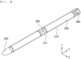
- FIG. 4 is a perspective view of a measurement member provided in the pouch cell deformation testing apparatus according to the first preferred embodiment of the present invention
- FIG. 5 is an exploded perspective view of the measurement member shown in FIG. 4 .
- the pouch cell deformation testing apparatus comprises a die unit 100, a measurement member 200, a driving unit 300, and a holding means 400.
- the die unit 100 may include a plate-shaped base 110 and a seating portion 120.
- the seating portion 120 which is disposed across the base 110, is configured to indicate the exact seating position of a pouch cell S, which is a target to be tested, and preferably protrudes slightly farther than an upper surface of the base 110.
- the measurement member 200 is located at one side surface or opposite side surfaces of the pouch cell S and is configured to physically determine the flatness of the pouch cell S, i.e. whether a bending phenomenon has occurred.
- the measurement member 200 may include a cylindrical hollow receiving portion 210, a moving bar 220 received in the hollow receiving portion 210, a dog 230 mounted to the moving bar 220, a spring 240, which is an elastic body, and a first sensing portion 250 located in the vicinity of the hollow receiving portion 210.
- the hollow receiving portion 210 is configured to guide the moving bar 220 having the dog 230 mounted thereto, and a viewing window 211 configured to allow the position of the dog 230 to be checked therethrough is provided in a predetermined region of the hollow receiving portion 210.
- the viewing window 211 may be blocked from the outside by a transparent material, such as glass, or may be simply open.
- the moving bar 220 having the dog 230 mounted thereto is movable depending on whether the pouch cell S is flat or not.
- one end of the moving bar 220 which has a cylindrical shape, is connected to one side of the spring 240, and the other side of the spring 240 is fixed to one side of the hollow receiving portion 210.
- a contact portion 222 located so as to protrude out of the hollow receiving portion 210 is provided at the other end of the moving bar 220.
- the moving bar 220 is immobile, but when pressed by a curved portion of the pouch cell S, i.e. an outwardly curved portion, the moving bar moves in a direction in which the spring 240 is located, and at this time the dog 230 also moves therewith.
- the moving bar 220 may be constituted by two pieces separable from each other, which may be fastened to each other, for example, by male and female engagement; however, the present invention is not limited thereto, and a fastening part therebetween is preferably provided at an extension portion 221 such that attachment and detachment of the dog 230 are easily achieved.
- a bar-shaped extension portion 221 having a reduced outer diameter may be provided at a set position of the moving bar 220, for example in the vicinity of the center thereof at which the pieces constituting the moving bar are connected to each other, and the dog 230 is mounted to the extension portion 221.
- the contact portion 222 is preferably approximately conical in shape, and is more preferably made of an elastic material, such as rubber or silicone, in order to prevent damage to the pouch cell S.
- an elastic material such as rubber or silicone
- the structure of the contact portion may be variously changed as long as the pouch cell S is not damaged.
- the contact portion may be a spring or may be configured in a form in which an outer surface of the spring is enclosed by rubber.
- the dog 230 will be described.
- the dog 230 is doughnut-shaped, is mounted to the extension portion 221 of the moving bar 220, and is located so as to be exposed through the viewing window 211 in the state in which the contact portion 222 of the moving bar 220 and the pouch cell S are not in contact.
- the dog 230 may be detected by the first sensing portion 250.
- the first sensing portion 250 is located orthogonal to the hollow receiving portion 210, and a first sensor 251 capable of recognizing the dog 230 is provided at the position of the dog that faces the viewing window 211.
- the first sensor 251 can detect the dog 230 only through the viewing window 211 of the hollow receiving portion 210, and cannot detect the dog 230 when the dog moves to the left and right of the viewing window 211.
- a coating layer made of colored ink is formed on an outer surface of the dog 230
- the first sensor 251 may be a color sensor capable of detecting the coating layer of the dog 230.
- the ink forming the coating layer on the outer surface of the dog 230 is formed in the shape of a band formed at a certain interval and a plurality of coating layers having different colors is provided, it is possible to detect the movement distance of the dog 230 through color change.
- the dog 230 and the first sensor 251 are not limited to the above example as long as the dog 230 is detectable.
- a bending phenomenon may occur along the overall width W of the pouch cell S, i.e. the surface thereof along which electrode leads are provided. Consequently, it is preferable for a plurality of hollow receiving portions 210 to be located so as to be spaced apart from each other by a certain distance along the overall width of the pouch cell S, and it is more preferable for the hollow receiving portions 210 to be located at a lower edge, at an upper edge, and between the lower edge and the upper edge of the pouch cell S.
- the hollow receiving portions 210 are located at one side edge, at the other side edge, and between the one side edge and the other side edge of the pouch cell S along the overall length L thereof, it is possible to determine whether the bending phenomenon has occurred in almost the entire region of the pouch cell S.
- the measurement members 200 are located at opposite side surfaces of the pouch cell S so as to correspond to each other, rather than only at one side surface of the pouch cell S. The reason for this is that, even when any one of the measurement members 200 malfunctions, it is possible to increase the accuracy of the test results.
- FIG. 6 is a perspective view of a modified measurement member provided in the pouch cell deformation testing apparatus according to the first preferred embodiment of the present invention. It is also possible to use the modified measurement member, as shown in FIG. 6 .
- a dog 230 having an approximately conical shape with the maximum outer diameter smaller than the outer diameter of a moving bar 220 is provided on an extension portion 221 of the moving bar 220, and a first sensor mounted to a first sensing portion is a proximity displacement sensor, such as a laser sensor, an ultrasonic sensor, or an infrared sensor.
- a proximity displacement sensor such as a laser sensor, an ultrasonic sensor, or an infrared sensor.
- the first sensor 251 is mounted to the first sensing portion 250.
- first sensing portion 250 is shown as being located at the base 110 in the figures, the present invention is not limited thereto.
- the holding means 400 is configured to move and temporarily hold a pouch cell S to be tested, and is not particularly restricted as long as the holding means does not cause damage to the pouch cell S.
- the holding means may be tongs or a vacuum suction plate.
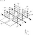
- FIG. 7 is a perspective view showing the structure in which the hollow receiving portion and the driving unit are coupled to each other in the pouch cell deformation testing apparatus according to the first preferred embodiment of the present invention.
- the hollow receiving portion 210 In order to check the bending phenomenon of the pouch cell S, the hollow receiving portion 210 must be located orthogonal to the side surface of the pouch cell S. Preferably, a plurality of hollow receiving portions 210 is used to check bent parts.
- the driving unit 300 is configured to move the hollow receiving portion 210 in a direction orthogonal to the side surface of the pouch cell S and to connect a plurality of hollow receiving portions 210 to each other.
- the driving unit 300 includes a first fixing bar 310 fastened to the hollow receiving portion 210, a second fixing bar 320 fastened to one side of the first fixing bar 310, a guide rail 330 configured to provide the movement path of the second fixing bar 320, and a linear motion member 340.
- the first fixing bar 310 is configured to fix and support the plurality of hollow receiving portions 210 disposed in the overall width direction of the pouch cell S, and is erected in a direction orthogonal to the hollow receiving portion 210, i.e. vertically.
- a fastening method or means is not particularly limited as long as the first fixing bar 310 and the hollow receiving portion 210 can be fastened to each other.
- two first fixing bars 310 are shown in the figures, which is only an example, and the number of the first fixing bars may be changed.
- the second fixing bar 320 is configured to fix and support the vertically erected first fixing bar 310, and is located parallel to the hollow receiving portion 210. A method of fastening therebetween is not particularly limited. Although the first fixing bar 310 and the second fixing bar 320 have been described separately, these fixing bars may be integrated into a single body.
- the guide rail 330 is configured to guide the second fixing bar 320 so as to accurately move in a direction orthogonal to the side surface of the pouch cell S, and may have a recessed groove formed in a longitudinal direction thereof.
- the linear motion member 340 connected to one side of the second fixing bar 320 is configured to reciprocate the second fixing bar 320 in a straight line, and is not particularly limited as long as it is possible to linearly move the second fixing bar 320 by a predetermined distance.
- the linear motion member is a servomotor or a pneumatic cylinder.
- FIG. 8 is a schematic view of a pouch cell deformation testing apparatus according to a second preferred embodiment of the present invention
- FIG. 9 is a perspective view of a measurement member provided in the pouch cell deformation testing apparatus according to the second preferred embodiment of the present invention.
- the testing apparatus is identical to the first embodiment except for a measurement member 200.
- the measurement member of the second embodiment includes a hollow receiving portion 210 and a second sensing portion 260 received in the hollow receiving portion 210, wherein a second sensor 261 capable of measuring the distance to the pouch cell S in a non-contact manner is mounted to the second sensing portion 260, and the second sensor is a proximity displacement sensor, such as a laser sensor, an ultrasonic sensor, or an infrared sensor.
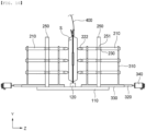
- FIG. 10 is a view illustrating the position of the dog when a normal pouch cell is mounted in the testing apparatus according to the first preferred embodiment of the present invention
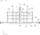
- FIG. 11 is a view illustrating the position of the dog when an abnormal pouch cell is mounted in the testing apparatus according to the first preferred embodiment of the present invention.
- a method of testing deformation of a pouch cell S includes a first step of locating the pouch cell S vertically, and a second step of determining whether the pouch cell S is normal based on the flatness of the pouch cell S using the measurement member 200 located at the side surface of the pouch cell S.
- the pouch cell S is located perpendicular to the ground or the base and fixed using the holding means 400.
- the overall length of the pouch cell S is parallel to the base in order to prevent electrode leads from colliding with the base.
- the receiving portion 210 is moved toward the side surface of the pouch cell S until the hollow receiving portion reaches a set position, more specifically until the hollow receiving portion comes into tight contact with or comes close to the pouch cell S, in the state in which the hollow receiving portion is located orthogonal to the side surface of the pouch cell S. At this time, it is obvious that the distance between the measurement member 200 and the pouch cell S must be measured in advance.
- the linear motion member 340 moves the plurality of hollow receiving portions 210 spaced apart from each other by a certain distance along the overall length and overall width of the pouch cell S, preferably toward one side surface of the pouch cell S, more preferably toward opposite side surfaces of the pouch cell S, and most preferably moves all of the hollow receiving portions 210 by the same distance.
- Whether the pouch cell S is normal is determined based on the position of the dog 230. As shown in FIG. 10 , when the pouch cell S is normal, i.e. there is no bending phenomenon, the contact portions 222 of the hollow receiving portions 210 that have been moved from opposite sides of the pouch cell S are simply in contact or very close to the side surfaces of the pouch cell S. As a result, all of the dogs 230 are exposed through the viewing windows 211 and may be detected by the first sensors 251.
- the portion of the pouch cell that is bent in a direction in which the hollow receiving portion 210 approaches pushes the contact portion 222 received in the hollow receiving portion 210, whereby the dog 230 cannot be located in the viewing window 211 and thus cannot be detected by the first sensor 251, or even though the dog 230 is located in the viewing window 211, the dog is moved beyond a set range, whereby only a part of the dog 230 is located in the viewing window.
- the pouch cell S is determined to be normal with no bending phenomenon, and when some of the dogs 230 are not detected, or the dogs 230 are moved beyond the set range even though the dogs are detected, the pouch cell S is determined to be abnormal.
- the pouch cell S When the pouch cell S is determined to be abnormal, it is preferable to further include a step of generating an alarm, such as a sound, for easy recognition by a worker.
- an alarm such as a sound
- FIG. 12 is a view illustrating the position of a second sensor when a normal pouch cell is mounted in the testing apparatus according to the second preferred embodiment of the present invention
- FIG. 13 is a view illustrating the position of the second sensor when an abnormal pouch cell is mounted in the testing apparatus according to the second preferred embodiment of the present invention.
- the second sensor 261 is located so as to be spaced apart from the pouch cell S by a certain distance, and then the distance between the pouch cell S and the second sensor 261 is measured. When all of the measured results are within a set range, the pouch cell is determined to be normal, and when one or more results deviate from the set range, the pouch cell is determined to be defective.
- the testing apparatus according to the second embodiment has the advantage that the testing apparatus does not need to be moved until the testing apparatus comes into tight contact with or comes close to the pouch cell S.
Landscapes
- Physics & Mathematics (AREA)
- General Physics & Mathematics (AREA)
- Chemical Kinetics & Catalysis (AREA)
- Electrochemistry (AREA)
- General Chemical & Material Sciences (AREA)
- Chemical & Material Sciences (AREA)
- Engineering & Computer Science (AREA)
- Manufacturing & Machinery (AREA)
- A Measuring Device Byusing Mechanical Method (AREA)
- Investigating Strength Of Materials By Application Of Mechanical Stress (AREA)
- Length Measuring Devices With Unspecified Measuring Means (AREA)
- Sealing Battery Cases Or Jackets (AREA)
- Secondary Cells (AREA)
Abstract
Description
- This application claims the benefit of priority to
Korean Patent Application No. 2022-0119267 filed on September 21, 2022 Korean Patent Application No. 2023-0098217 filed on July 27, 2023 - The present invention relates to a pouch cell deformation testing apparatus and a pouch cell deformation testing method using the same, and more particularly to a pouch cell deformation testing apparatus capable of measuring whether a bending phenomenon has occurred in a pouch cell during an activation process or after the activation process and a pouch cell deformation testing method using the same.
- With recent development of alternative energies due to air pollution and energy depletion caused as the result of use of fossil fuels, demand for secondary batteries capable of storing electrical energy that is produced has increased. Secondary batteries, which are capable of being charged and discharged, are intimately used in daily life. For example, secondary batteries are used in mobile devices, electric vehicles, and hybrid electric vehicles.
- Based on the structure of an electrode assembly, secondary batteries are classified into a cylindrical secondary battery, a prismatic secondary battery, and a pouch-shaped secondary battery. Thereamong, the pouch-shaped secondary battery is gradually increasing in use because it is possible to obtain high-capacity, high-density secondary batteries, to reduce manufacturing cost, to reduce weight, and to provide various shapes.
- The pouch-shaped secondary battery is manufactured by laminating a lower separator, a negative electrode, an upper separator, and a positive electrode in that order, applying heat and pressure thereto through a roll lamination process, and stacking dozens of monocells obtained by cutting. However, a bending phenomenon in which an electrode assembly obtained by lamination is bent in an overall width direction may occur due to various reasons.
- In addition, during an activation process of charging, discharging, and stabilizing the pouch-shaped secondary battery, the difference in adhesion between the electrode and the separator in the cell may be generated, whereby the bending phenomenon may occur.
- Since bent secondary batteries are at risk of colliding with equipment during transportation to a subsequent process, such as packaging, or ignition due to falling, a series of testing processes to identify deformed secondary batteries is essential.
- In connection therewith, Patent Document 1 discloses an apparatus for testing the deformation of a battery container. That is, a pair of pressing plates 2 connected to driven shafts 1 that may be located at opposite side surfaces of a
prismatic battery container 10 is provided, and the pressing plates 2 are brought into tight contact with the surface of thebattery container 10 to measure the thickness of thedeformed battery container 10. - However, in the case of a pouch-shaped battery cell, it is difficult to determine whether the pouch-shaped battery cell has been deformed using the pressing plates because the external shape of the pouch-shaped battery cell is relatively easily changed, and it is impossible to determine which part of the pouch-shaped battery cell has been deformed.
- (Patent Document 1)
Japanese Patent Application Publication No. 2014-165059 - The present invention has been made in view of the above problems, and it is an object of the present invention to provide a pouch cell deformation testing apparatus capable of testing deformation of a pouch cell that is easy to change in external shape and a testing method using the same.
- It is another object of the present invention to provide a pouch cell deformation testing apparatus capable of checking the deformed position of a pouch cell when the pouch cell is deformed and a testing method using the same.
- It is a further object of the present invention to provide a pouch cell deformation testing apparatus capable of checking deformation of a pouch cell that is difficult to check with the naked eye before a degassing process and a testing method using the same.
- A pouch cell deformation testing apparatus according to the present invention to accomplish the above objects includes a die unit (100) configured to allow a pouch cell (S) to be seated thereon in an erected state and a measurement member (200) located above the die unit (100), the measurement member being configured to measure a flatness of the pouch cell (S).
- Also, in the pouch cell deformation testing apparatus according to the present invention, the measurement member (200) may be located at a side surface of the pouch cell (S) .
- Also, in the pouch cell deformation testing apparatus according to the present invention, a plurality of measurement members (200) may be provided in an overall length direction of the pouch cell (S).
- Also, in the pouch cell deformation testing apparatus according to the present invention, the measurement member (200) may include a hollow receiving portion (210) having a viewing window (211), a moving bar (220) received in the hollow receiving portion (210), a dog (230) mounted to the moving bar (220), a spring (240) received in the hollow receiving portion (210), one end of the spring being fixed to the hollow receiving portion (210), an other end of the spring being connected to one end of the moving bar (220), and a first sensing portion (250) located in a vicinity of the hollow receiving portion (210), wherein the dog (230) may be exposed to the outside through the viewing window (211), wherein a contact portion (222) protruding out of the hollow receiving portion (210) may be provided at an other end of the moving bar (220), and wherein the first sensing portion (250) may detect the dog (230) only when the dog is exposed to the outside through the viewing window (211) .
- Also, in the pouch cell deformation testing apparatus according to the present invention, the contact portion (222) may be made of an elastic material and may be conical in shape.
- Also, the pouch cell deformation testing apparatus according to the present invention may further include a driving unit (300) configured to move the hollow receiving portion (210) forwards toward the side surface of the pouch cell (S) or rearwards, wherein the driving unit (300) may include a first fixing bar (310) located vertically and fastened to the measurement member (200), a second fixing bar (320) fastened to one side of the first fixing bar (310) and located parallel to the measurement member (200), a guide rail (330) configured to provide the movement path of the second fixing bar (320), and a linear motion member (340) configured to reciprocate the second fixing bar (320) in a straight line by a set distance.
- Also, in the pouch cell deformation testing apparatus according to the present invention, the hollow receiving portion (210) may include a plurality of hollow receiving portions spaced apart from each other by a certain distance in an overall width direction of the pouch cell (S), and the first fixing bar (310) may be fastened to the plurality of hollow receiving portions (210).
- Also, in the pouch cell deformation testing apparatus according to the present invention, the hollow receiving portions (210) may be located at a lower edge, at an upper edge, and between the lower edge and the upper edge of the pouch cell (S) in the overall width direction of the pouch cell (S).
- Also, in the pouch cell deformation testing apparatus according to the present invention, the hollow receiving portions (210) may be located at one side edge, at an other side edge, and between the one side edge and the other side edge of the pouch cell (S) in the overall length direction.
- Also, in the pouch cell deformation testing apparatus according to the present invention, the measurement member (200) may include a hollow receiving portion (210) and a second sensing portion (260) received in the hollow receiving portion (210), and the second sensing portion (260) may be provided with a second sensor (261) configured to measure the distance to the pouch cell (S) in a non-contact manner.
- In addition, a pouch cell deformation testing method according to the present invention includes a first step of locating a pouch cell (S) disposed vertically and a second step of determining whether the pouch cell (S) is normal based on a flatness of the pouch cell (S) using a measurement member (200) located at a side surface of the pouch cell, wherein the measurement member (200) measures the flatness of the pouch cell (S) in a contact manner or a non-contact manner.
- Also, in the pouch cell deformation testing method according to the present invention, the measurement member (200) may include a hollow receiving portion (210) having a viewing window (211), a moving bar (220) received in the hollow receiving portion (210), a dog (230) mounted to the moving bar (220), a spring (240) received in the hollow receiving portion (210), one end of the spring being fixed to the hollow receiving portion (210), an other end of the spring being connected to one end of the moving bar (220), and a first sensing portion (250) located in a vicinity of the hollow receiving portion (210), and in the second step, the hollow receiving portion (210) is moved toward the side surface of the pouch cell (S) until the hollow receiving portion reaches a set position, in the state in which the hollow receiving portion is located orthogonal to the side surface of the pouch cell (S), when the dog (230) is exposed to the outside through the viewing window (211) and the first sensing portion (250) detects the dog (230), the pouch cell may be determined to be normal, and when the first sensing portion does not detect the dog, the pouch cell may be determined to be abnormal.
- Also, in the pouch cell deformation testing method according to the present invention, a plurality of measurement members (200) may be provided at one side surface or opposite side surfaces of the pouch cell.
- Also, in the pouch cell deformation testing method according to the present invention, in the second step, a plurality of hollow receiving portions (210) spaced apart from each other by a certain distance along an overall length of the pouch cell (S) may be moved to the one side surface or the opposite side surfaces of the pouch cell (S).
- Also, in the pouch cell deformation testing method according to the present invention, in the second step, a plurality of hollow receiving portions (210) spaced apart from each other by a certain distance along an overall width of the pouch cell (S) may be moved to the one side surface or the opposite side surfaces of the pouch cell (S).
- Also, in the pouch cell deformation testing method according to the present invention, when the dog (230) is not detected in the second step, an alarm may be generated.
- As is apparent from the above description, a pouch cell deformation testing apparatus according to the present invention and a pouch cell deformation testing method using the same have an advantage in that it is possible to determine whether a pouch cell has been deformed in a contact manner or a non-contact manner.
- In addition, the pouch cell deformation testing apparatus according to the present invention and the pouch cell deformation testing method using the same have an advantage in that a dog movable to one side surface or opposite side surface of the pouch cell and a sensing portion capable of detecting the dog are provided, whereby it is possible to easily determine whether the pouch cell has been deformed.
- In addition, the pouch cell deformation testing apparatus according to the present invention and the pouch cell deformation testing method using the same have a merit in that a plurality of dogs movable to one side surface or opposite side surface of the pouch cell and a sensing portion capable of detecting the dogs are provided, whereby it is possible to check the deformed position of the pouch cell.
- Furthermore, the pouch cell deformation testing apparatus according to the present invention and the pouch cell deformation testing method using the same have an advantage in that a plurality of dogs movable to one side surface or opposite side surface of the pouch cell is detected, whereby it is possible to measure the degree of deformation of the pouch cell.
-
-
FIG. 1 is a perspective view of a conventional apparatus for testing deformation of a battery container. -
FIG. 2 is a view showing the state in which a pouch cell is mounted in a pouch cell deformation testing apparatus according to a first preferred embodiment of the present invention. -
FIG. 3 is a schematic view of the pouch cell deformation testing apparatus according to the first preferred embodiment of the present invention. -
FIG. 4 is a perspective view of a measurement member provided in the pouch cell deformation testing apparatus according to the first preferred embodiment of the present invention. -
FIG. 5 is an exploded perspective view of the measurement member shown inFIG. 4 . -
FIG. 6 is a perspective view of a modified measurement member provided in the pouch cell deformation testing apparatus according to the first preferred embodiment of the present invention. -
FIG. 7 is a perspective view showing the structure in which the measurement member and a driving unit are coupled to each other in the pouch cell deformation testing apparatus according to the first preferred embodiment of the present invention. -
FIG. 8 is a schematic view of a pouch cell deformation testing apparatus according to a second preferred embodiment of the present invention. -
FIG. 9 is a perspective view of a measurement member provided in the pouch cell deformation testing apparatus according to the second preferred embodiment of the present invention. -
FIG. 10 is a view illustrating the position of a dog when a normal pouch cell is mounted in the testing apparatus according to the first preferred embodiment of the present invention. -
FIG. 11 is a view illustrating the position of the dog when an abnormal pouch cell is mounted in the testing apparatus according to the first preferred embodiment of the present invention. -
FIG. 12 is a view illustrating the position of a second sensor when a normal pouch cell is mounted in the testing apparatus according to the second preferred embodiment of the present invention. -
FIG. 13 is a view illustrating the position of the second sensor when an abnormal pouch cell is mounted in the testing apparatus according to the second preferred embodiment of the present invention. - Now, preferred embodiments of the present invention will be described in detail with reference to the accompanying drawings such that the preferred embodiments of the present invention can be easily implemented by a person having ordinary skill in the art to which the present invention pertains. In describing the principle of operation of the preferred embodiments of the present invention in detail, however, a detailed description of known functions and configurations incorporated herein will be omitted when the same may obscure the subject matter of the present invention.
- In addition, the same reference numbers will be used throughout the drawings to refer to parts that perform similar functions or operations. In the case in which one part is the to be connected to another part in the entire specification, not only may the one part be directly connected to the other part, but also, the one part may be indirectly connected to the other part via a further part. In addition, that a certain element is included does not mean that other elements are excluded, but means that such elements may be further included unless mentioned otherwise.
- Hereinafter, a pouch cell deformation testing apparatus according to the present invention and a testing method using the same will be described with reference to the accompanying drawings.
-
FIG. 2 is a view showing the state in which a pouch cell is mounted in a pouch cell deformation testing apparatus according to a first preferred embodiment of the present invention,FIG. 3 is a schematic view of the pouch cell deformation testing apparatus according to the first preferred embodiment of the present invention,FIG. 4 is a perspective view of a measurement member provided in the pouch cell deformation testing apparatus according to the first preferred embodiment of the present invention, andFIG. 5 is an exploded perspective view of the measurement member shown inFIG. 4 . - As shown in
FIGs. 2 to 5 , the pouch cell deformation testing apparatus according to the first embodiment of the present invention comprises adie unit 100, ameasurement member 200, adriving unit 300, and a holding means 400. - First, the
die unit 100 may include a plate-shapedbase 110 and aseating portion 120. Theseating portion 120, which is disposed across thebase 110, is configured to indicate the exact seating position of a pouch cell S, which is a target to be tested, and preferably protrudes slightly farther than an upper surface of thebase 110. - The
measurement member 200 is located at one side surface or opposite side surfaces of the pouch cell S and is configured to physically determine the flatness of the pouch cell S, i.e. whether a bending phenomenon has occurred. - The
measurement member 200 may include a cylindrical hollow receivingportion 210, a movingbar 220 received in the hollow receivingportion 210, adog 230 mounted to the movingbar 220, aspring 240, which is an elastic body, and afirst sensing portion 250 located in the vicinity of the hollow receivingportion 210. - First, the hollow receiving
portion 210 is configured to guide the movingbar 220 having thedog 230 mounted thereto, and aviewing window 211 configured to allow the position of thedog 230 to be checked therethrough is provided in a predetermined region of the hollow receivingportion 210. - Here, the
viewing window 211 may be blocked from the outside by a transparent material, such as glass, or may be simply open. - The moving
bar 220 having thedog 230 mounted thereto is movable depending on whether the pouch cell S is flat or not. - Specifically, one end of the moving
bar 220, which has a cylindrical shape, is connected to one side of thespring 240, and the other side of thespring 240 is fixed to one side of the hollow receivingportion 210. - In addition, a
contact portion 222 located so as to protrude out of the hollow receivingportion 210 is provided at the other end of the movingbar 220. When no external force is applied, therefore, the movingbar 220 is immobile, but when pressed by a curved portion of the pouch cell S, i.e. an outwardly curved portion, the moving bar moves in a direction in which thespring 240 is located, and at this time thedog 230 also moves therewith. - The moving
bar 220 may be constituted by two pieces separable from each other, which may be fastened to each other, for example, by male and female engagement; however, the present invention is not limited thereto, and a fastening part therebetween is preferably provided at anextension portion 221 such that attachment and detachment of thedog 230 are easily achieved. - In other words, a bar-shaped
extension portion 221 having a reduced outer diameter may be provided at a set position of the movingbar 220, for example in the vicinity of the center thereof at which the pieces constituting the moving bar are connected to each other, and thedog 230 is mounted to theextension portion 221. - The
contact portion 222 is preferably approximately conical in shape, and is more preferably made of an elastic material, such as rubber or silicone, in order to prevent damage to the pouch cell S. Of course, the structure of the contact portion may be variously changed as long as the pouch cell S is not damaged. For example, the contact portion may be a spring or may be configured in a form in which an outer surface of the spring is enclosed by rubber. - Next, the
dog 230 will be described. As previously described, thedog 230 is doughnut-shaped, is mounted to theextension portion 221 of the movingbar 220, and is located so as to be exposed through theviewing window 211 in the state in which thecontact portion 222 of the movingbar 220 and the pouch cell S are not in contact. - The
dog 230 may be detected by thefirst sensing portion 250. Specifically, thefirst sensing portion 250 is located orthogonal to the hollow receivingportion 210, and afirst sensor 251 capable of recognizing thedog 230 is provided at the position of the dog that faces theviewing window 211. - Consequently, the
first sensor 251 can detect thedog 230 only through theviewing window 211 of the hollow receivingportion 210, and cannot detect thedog 230 when the dog moves to the left and right of theviewing window 211. - For example, a coating layer made of colored ink is formed on an outer surface of the
dog 230, and thefirst sensor 251 may be a color sensor capable of detecting the coating layer of thedog 230. In particular, when the ink forming the coating layer on the outer surface of thedog 230 is formed in the shape of a band formed at a certain interval and a plurality of coating layers having different colors is provided, it is possible to detect the movement distance of thedog 230 through color change. - Of course, the
dog 230 and thefirst sensor 251 are not limited to the above example as long as thedog 230 is detectable. - After an activation process, a bending phenomenon may occur along the overall width W of the pouch cell S, i.e. the surface thereof along which electrode leads are provided. Consequently, it is preferable for a plurality of hollow receiving
portions 210 to be located so as to be spaced apart from each other by a certain distance along the overall width of the pouch cell S, and it is more preferable for the hollow receivingportions 210 to be located at a lower edge, at an upper edge, and between the lower edge and the upper edge of the pouch cell S. - When the hollow receiving
portions 210 are located, as described above, it is possible to determine whether the bending phenomenon has occurred in a certain region of the overall width W. - In particular, when the hollow receiving
portions 210 are located at one side edge, at the other side edge, and between the one side edge and the other side edge of the pouch cell S along the overall length L thereof, it is possible to determine whether the bending phenomenon has occurred in almost the entire region of the pouch cell S. - Meanwhile, it is preferable for the
measurement members 200 to be located at opposite side surfaces of the pouch cell S so as to correspond to each other, rather than only at one side surface of the pouch cell S. The reason for this is that, even when any one of themeasurement members 200 malfunctions, it is possible to increase the accuracy of the test results. -
FIG. 6 is a perspective view of a modified measurement member provided in the pouch cell deformation testing apparatus according to the first preferred embodiment of the present invention. It is also possible to use the modified measurement member, as shown inFIG. 6 . - That is, in the modified measurement member, a
dog 230 having an approximately conical shape with the maximum outer diameter smaller than the outer diameter of a movingbar 220 is provided on anextension portion 221 of the movingbar 220, and a first sensor mounted to a first sensing portion is a proximity displacement sensor, such as a laser sensor, an ultrasonic sensor, or an infrared sensor. When the modified measurement member is used, it is not only possible to determine whether adog 230 is located in aviewing window 211 but also possible to check the movement distance of thedog 230 due to the conical shape thereof. - Referring back to
FIGs. 2 to 5 , thefirst sensor 251 is mounted to thefirst sensing portion 250. In order to detect alldogs 230, it is preferable to provide the same number offirst sensors 251 as theviewing windows 211 of the hollow receivingportions 210, and it is more preferable for the first sensors to be located on the same horizontal lines as theviewing windows 211. - Although the
first sensing portion 250 is shown as being located at the base 110 in the figures, the present invention is not limited thereto. - Meanwhile, the holding means 400 is configured to move and temporarily hold a pouch cell S to be tested, and is not particularly restricted as long as the holding means does not cause damage to the pouch cell S. As an example, the holding means may be tongs or a vacuum suction plate.
-
FIG. 7 is a perspective view showing the structure in which the hollow receiving portion and the driving unit are coupled to each other in the pouch cell deformation testing apparatus according to the first preferred embodiment of the present invention. - In order to check the bending phenomenon of the pouch cell S, the hollow receiving
portion 210 must be located orthogonal to the side surface of the pouch cell S. Preferably, a plurality of hollow receivingportions 210 is used to check bent parts. - The driving
unit 300 is configured to move the hollow receivingportion 210 in a direction orthogonal to the side surface of the pouch cell S and to connect a plurality of hollow receivingportions 210 to each other. - Specifically, the driving
unit 300 includes afirst fixing bar 310 fastened to the hollow receivingportion 210, asecond fixing bar 320 fastened to one side of the first fixingbar 310, aguide rail 330 configured to provide the movement path of thesecond fixing bar 320, and alinear motion member 340. - The
first fixing bar 310 is configured to fix and support the plurality of hollow receivingportions 210 disposed in the overall width direction of the pouch cell S, and is erected in a direction orthogonal to the hollow receivingportion 210, i.e. vertically. Here, a fastening method or means is not particularly limited as long as the first fixingbar 310 and the hollow receivingportion 210 can be fastened to each other. Although two first fixing bars 310 are shown in the figures, which is only an example, and the number of the first fixing bars may be changed. - The
second fixing bar 320 is configured to fix and support the vertically erected first fixingbar 310, and is located parallel to the hollow receivingportion 210. A method of fastening therebetween is not particularly limited. Although the first fixingbar 310 and thesecond fixing bar 320 have been described separately, these fixing bars may be integrated into a single body. - The
guide rail 330 is configured to guide thesecond fixing bar 320 so as to accurately move in a direction orthogonal to the side surface of the pouch cell S, and may have a recessed groove formed in a longitudinal direction thereof. - The
linear motion member 340 connected to one side of thesecond fixing bar 320 is configured to reciprocate thesecond fixing bar 320 in a straight line, and is not particularly limited as long as it is possible to linearly move thesecond fixing bar 320 by a predetermined distance. Preferably, the linear motion member is a servomotor or a pneumatic cylinder. -
FIG. 8 is a schematic view of a pouch cell deformation testing apparatus according to a second preferred embodiment of the present invention, andFIG. 9 is a perspective view of a measurement member provided in the pouch cell deformation testing apparatus according to the second preferred embodiment of the present invention. - The testing apparatus according to the second preferred embodiment of the present invention is identical to the first embodiment except for a
measurement member 200. In other words, the measurement member of the second embodiment includes ahollow receiving portion 210 and asecond sensing portion 260 received in the hollow receivingportion 210, wherein asecond sensor 261 capable of measuring the distance to the pouch cell S in a non-contact manner is mounted to thesecond sensing portion 260, and the second sensor is a proximity displacement sensor, such as a laser sensor, an ultrasonic sensor, or an infrared sensor. - Next, a pouch cell deformation testing method using the testing apparatus according to the first preferred embodiment of the present invention described above will be described.
-
FIG. 10 is a view illustrating the position of the dog when a normal pouch cell is mounted in the testing apparatus according to the first preferred embodiment of the present invention, andFIG. 11 is a view illustrating the position of the dog when an abnormal pouch cell is mounted in the testing apparatus according to the first preferred embodiment of the present invention. - Referring to these figures, a method of testing deformation of a pouch cell S according to the present invention includes a first step of locating the pouch cell S vertically, and a second step of determining whether the pouch cell S is normal based on the flatness of the pouch cell S using the
measurement member 200 located at the side surface of the pouch cell S. - First, in the first step, the pouch cell S is located perpendicular to the ground or the base and fixed using the holding means 400. Of course, the overall length of the pouch cell S is parallel to the base in order to prevent electrode leads from colliding with the base.
- In the second step, the receiving
portion 210 is moved toward the side surface of the pouch cell S until the hollow receiving portion reaches a set position, more specifically until the hollow receiving portion comes into tight contact with or comes close to the pouch cell S, in the state in which the hollow receiving portion is located orthogonal to the side surface of the pouch cell S. At this time, it is obvious that the distance between themeasurement member 200 and the pouch cell S must be measured in advance. - The
linear motion member 340 moves the plurality of hollow receivingportions 210 spaced apart from each other by a certain distance along the overall length and overall width of the pouch cell S, preferably toward one side surface of the pouch cell S, more preferably toward opposite side surfaces of the pouch cell S, and most preferably moves all of the hollow receivingportions 210 by the same distance. - Whether the pouch cell S is normal is determined based on the position of the
dog 230. As shown inFIG. 10 , when the pouch cell S is normal, i.e. there is no bending phenomenon, thecontact portions 222 of the hollow receivingportions 210 that have been moved from opposite sides of the pouch cell S are simply in contact or very close to the side surfaces of the pouch cell S. As a result, all of thedogs 230 are exposed through theviewing windows 211 and may be detected by thefirst sensors 251. - On the other hand, when the pouch cell S is abnormal, i.e. a bending phenomenon has occurred at a part of the pouch cell, as shown in
FIG. 11 , some of thecontact portions 222 of the hollow receivingportions 210 that have been moved from opposite sides of the pouch cell S cannot be moved to set positions. - In other words, the portion of the pouch cell that is bent in a direction in which the hollow receiving
portion 210 approaches pushes thecontact portion 222 received in the hollow receivingportion 210, whereby thedog 230 cannot be located in theviewing window 211 and thus cannot be detected by thefirst sensor 251, or even though thedog 230 is located in theviewing window 211, the dog is moved beyond a set range, whereby only a part of thedog 230 is located in the viewing window. - As described above, when all of the
dogs 230 are detected, the pouch cell S is determined to be normal with no bending phenomenon, and when some of thedogs 230 are not detected, or thedogs 230 are moved beyond the set range even though the dogs are detected, the pouch cell S is determined to be abnormal. - When the pouch cell S is determined to be abnormal, it is preferable to further include a step of generating an alarm, such as a sound, for easy recognition by a worker.
- Meanwhile, when a
measurement member 200 having adog 230 having a conical shape with the configuration shown inFIG. 6 is used, it is possible to determine whether the pouch cell S is defective by measuring the distance between thedog 230 and thefirst sensor 251. -
FIG. 12 is a view illustrating the position of a second sensor when a normal pouch cell is mounted in the testing apparatus according to the second preferred embodiment of the present invention, andFIG. 13 is a view illustrating the position of the second sensor when an abnormal pouch cell is mounted in the testing apparatus according to the second preferred embodiment of the present invention. - When the testing apparatus according to the second embodiment is used, the
second sensor 261 is located so as to be spaced apart from the pouch cell S by a certain distance, and then the distance between the pouch cell S and thesecond sensor 261 is measured. When all of the measured results are within a set range, the pouch cell is determined to be normal, and when one or more results deviate from the set range, the pouch cell is determined to be defective. - Compared to the testing apparatus according to the first embodiment, the testing apparatus according to the second embodiment has the advantage that the testing apparatus does not need to be moved until the testing apparatus comes into tight contact with or comes close to the pouch cell S.
- The present invention has been described above with reference to specific embodiments. However, those skilled in the art to which the present invention pertains will appreciate that various applications and modifications are possible within the category of the present invention based on the above description.
-
- 100:
- Die unit
- 110:
- Base
- 120:
- Seating portion
- 200:
- Measurement member
- 210:
- Receiving portion 211: Viewing window
- 220:
- Moving bar
- 221:
- Extension portion 222: Contact portion
- 230:
- Dog
- 240:
- Spring
- 250:
- First sensing portion 251: First sensor
- 260:
- Second sensing portion 261: Second sensor
- 300:
- Driving unit
- 310:
- First fixing bar
- 320:
- Second fixing bar
- 330:
- Guide rail
- 340:
- Linear motion member
- 400:
- Holding means
- S:
- Pouch cell
- L:
- Overall length
- W:
- Overall width
Claims (16)
- A pouch cell deformation testing apparatus comprising:a die unit configured to allow a pouch cell to be seated thereon in an erected state; anda measurement member located above the die unit, the measurement member being configured to measure a flatness of the pouch cell.
- The pouch cell deformation testing apparatus according to claim 1, wherein the measurement member is located at a side surface of the pouch cell.
- The pouch cell deformation testing apparatus according to claim 2, wherein a plurality of measurement members are provided in an overall length direction of the pouch cell.
- The pouch cell deformation testing apparatus according to claim 3, wherein the measurement member comprises:a hollow receiving portion having a viewing window,a moving bar received in the hollow receiving portion,a dog mounted to the moving bar,a spring received in the hollow receiving portion, andone end of the spring being fixed to the receiving portion, an other end of the spring being connected hollow a first sensing portion located in a vicinity of the hollow receiving portion,wherein the dog is exposed to an outside through the viewing window,wherein a contact portion protruding out of the hollow receiving portion is provided at an other end of the moving bar, andwherein the first sensing portion detects the dog only when the dog is exposed to the outside through the viewing window.
- The pouch cell deformation testing apparatus according to claim 4, wherein the contact portion is made of an elastic material and is conical in shape.
- The pouch cell deformation testing apparatus according to claim 4, further comprising:a driving unit configured to move the hollow receiving portion forwards toward the side surface of the pouch cell or rearwards,wherein the driving unit comprises:a first fixing bar located vertically and fastened to the measurement member,a second fixing bar fastened to one side of the first fixing bar and located parallel to the measurement member,a guide rail configured to provide a movement path of the second fixing bar, anda linear motion member configured to reciprocate the second fixing bar in a straight line by a set distance.
- The pouch cell deformation testing apparatus according to claim 6, wherein the hollow receiving portion comprises a plurality of hollow receiving portions spaced apart from each other by a certain distance in an overall width direction of the pouch cell, and
wherein the first fixing bar is fastened to the plurality of hollow receiving portions. - The pouch cell deformation testing apparatus according to claim 7, wherein the hollow receiving portions are located at a lower edge, at an upper edge, and between the lower edge and the upper edge of the pouch cell in the overall width direction of the pouch cell.
- The pouch cell deformation testing apparatus according to claim 7, wherein the hollow receiving portions are located at one side edge, at an other side edge, and between the one side edge and the other side edge of the pouch cell in the overall length direction.
- The pouch cell deformation testing apparatus according to claim 3, wherein the measurement member comprises:a hollow receiving portion, anda second sensing portion received in the hollow receiving portion,wherein the second sensing portion is provided with a second sensor configured to measure a distance to the pouch cell in a non-contact manner.
- A pouch cell deformation testing method comprising:a first step of locating a pouch cell disposed vertically; anda second step of determining whether the pouch cell is normal based on a flatness of the pouch cell using a measurement member located at a side surface of the pouch cell,wherein the measurement member measures the flatness of the pouch cell in a contact manner or a non-contact manner.
- The pouch cell deformation testing method according to claim 11, wherein the measurement member comprises:a hollow receiving portion having a viewing window,a moving bar received in the hollow receiving portion,a dog mounted to the moving bar,a spring received in the hollow receiving portion, one end of the spring being fixed to the hollow receiving portion, an other end of the spring being connected to one end of the moving bar, anda first sensing portion located in a vicinity of the hollow receiving portion,wherein in the second step, the hollow receiving portion is moved toward the side surface of the pouch cell until the hollow receiving portion reaches a set position, in a state in which the hollow receiving portion is located orthogonal to the side surface of the pouch cell,wherein when the dog is exposed to an outside through the viewing window and the first sensing portion detects the dog, the pouch cell is determined to be normal, and when the first sensing portion does not detect the dog, the pouch cell is determined to be abnormal.
- The pouch cell deformation testing method according to claim 12, wherein a plurality of measurement members are provided at one side surface or opposite side surfaces of the pouch cell.
- The pouch cell deformation testing method according to claim 13, wherein, in the second step, a plurality of hollow receiving portions spaced apart from each other by a certain distance along an overall length of the pouch cell are moved to the one side surface or the opposite side surfaces of the pouch cell.
- The pouch cell deformation testing method according to claim 13, wherein, in the second step, a plurality of hollow receiving portions spaced apart from each other by a certain distance along an overall width of the pouch cell are moved to the one side surface or the opposite side surfaces of the pouch cell.
- The pouch cell deformation testing method according to claim 12, wherein, when the dog is not detected in the second step, an alarm is generated.
Applications Claiming Priority (3)
| Application Number | Priority Date | Filing Date | Title |
|---|---|---|---|
| KR20220119267 | 2022-09-21 | ||
| KR1020230098217A KR20240040615A (en) | 2022-09-21 | 2023-07-27 | Device and method for inspecting deformation of pouch cell |
| PCT/KR2023/011714 WO2024063335A1 (en) | 2022-09-21 | 2023-08-09 | Pouch cell deformation inspection device and deformation inspection method using same |
Publications (2)
| Publication Number | Publication Date |
|---|---|
| EP4439776A1 true EP4439776A1 (en) | 2024-10-02 |
| EP4439776A4 EP4439776A4 (en) | 2025-05-21 |
Family
ID=90454597
Family Applications (1)
| Application Number | Title | Priority Date | Filing Date |
|---|---|---|---|
| EP23868394.0A Pending EP4439776A4 (en) | 2022-09-21 | 2023-08-09 | Apparatus for inspecting the deformation of pouch cells and method for deformation inspection therewith |
Country Status (4)
| Country | Link |
|---|---|
| US (1) | US20250164228A1 (en) |
| EP (1) | EP4439776A4 (en) |
| JP (1) | JP7827257B2 (en) |
| WO (1) | WO2024063335A1 (en) |
Families Citing this family (1)
| Publication number | Priority date | Publication date | Assignee | Title |
|---|---|---|---|---|
| CN119526682B (en) * | 2025-01-21 | 2025-05-09 | 南京轶诺科技有限公司 | Automatic feeding device for filter screen assembly |
Family Cites Families (10)
| Publication number | Priority date | Publication date | Assignee | Title |
|---|---|---|---|---|
| JP2014165059A (en) | 2013-02-26 | 2014-09-08 | Mitsubishi Heavy Ind Ltd | Battery container deformation inspection equipment |
| KR102114962B1 (en) * | 2018-07-17 | 2020-06-05 | (주)휴민텍 | Pouch type battery cell inspection unit |
| KR102813413B1 (en) * | 2019-08-27 | 2025-05-27 | 주식회사 엘지에너지솔루션 | Thickness measurement apparatus and thickness measurement apparatus for unit cell |
| KR102917121B1 (en) * | 2020-03-09 | 2026-01-22 | 주식회사 엘지에너지솔루션 | Battery module swelling measuring apparatus |
| CN212871158U (en) * | 2020-08-31 | 2021-04-02 | 蜂巢能源科技有限公司 | Cell thickness measuring device |
| KR102647938B1 (en) * | 2020-09-14 | 2024-03-15 | 엘지전자 주식회사 | Pouch battery thickness measurement device |
| JP2023548296A (en) | 2020-11-11 | 2023-11-16 | アクセリス テクノロジーズ, インコーポレイテッド | Hybrid high temperature electrostatic clamp to improve workpiece temperature uniformity |
| KR20220119267A (en) | 2021-02-20 | 2022-08-29 | 조윤 | Phone charger fixer that is not easily separated from the phone |
| CN215217474U (en) * | 2021-04-29 | 2021-12-17 | 东莞市德鑫美精密制造有限公司 | Battery cover plate flatness detection jig |
| CN216410060U (en) | 2021-11-29 | 2022-04-29 | 苏州胜百锐精密机械有限公司 | New energy battery mould accessory roughness inspection device |
-
2023
- 2023-08-09 US US18/832,452 patent/US20250164228A1/en active Pending
- 2023-08-09 JP JP2024538252A patent/JP7827257B2/en active Active
- 2023-08-09 EP EP23868394.0A patent/EP4439776A4/en active Pending
- 2023-08-09 WO PCT/KR2023/011714 patent/WO2024063335A1/en not_active Ceased
Also Published As
| Publication number | Publication date |
|---|---|
| JP2024545338A (en) | 2024-12-05 |
| JP7827257B2 (en) | 2026-03-10 |
| US20250164228A1 (en) | 2025-05-22 |
| EP4439776A4 (en) | 2025-05-21 |
| WO2024063335A1 (en) | 2024-03-28 |
Similar Documents
| Publication | Publication Date | Title |
|---|---|---|
| KR20190011565A (en) | Apparatus and method for testing a battery pack | |
| KR101875535B1 (en) | Size checking apparatus for battery case | |
| EP4098393A1 (en) | Apparatus for bending and welding electrode lead, and method for welding electrode lead using same | |
| EP4026651B1 (en) | Welding quality inspection device | |
| US20250164228A1 (en) | Pouch cell deformation testing apparatus and deformation testing method using the same | |
| KR102768401B1 (en) | Short testing apparatus and checking method for deformation of electrode-tab using the short testing apparatus | |
| US20240255376A1 (en) | Shock Test Apparatus for Pouch-Shaped Battery Cells and Shock Test Method for Pouch-Shaped Battery Cells Using the Same | |
| CN117062703A (en) | Equipment and methods for forming bags | |
| KR20230029203A (en) | Tab fold detection device for secondary battery and method for detecting tab fold using the same | |
| US12298278B2 (en) | Battery cell weld portion inspection apparatus and battery cell weld portion inspection method using the same | |
| US20220352592A1 (en) | System and Method for Inspecting Degree of Alignment of Battery Module | |
| KR101994346B1 (en) | Charging-Discharging Apparatus Capable of Measuring Thickness of Battery Cell | |
| US12281894B2 (en) | Welding rod inspection apparatus for measuring whether welding rod is normal and inspection method using the same | |
| KR20170019211A (en) | Pouch sealing gap measuring apparatus | |
| CN118575328A (en) | Pouch type battery cell deformation testing device and deformation testing method using same | |
| KR20150050116A (en) | Short measuring apparatus of unit cell | |
| KR20240040615A (en) | Device and method for inspecting deformation of pouch cell | |
| KR20220099414A (en) | Measuring Method Of Sealing Gap Of Pouch Battery Cell | |
| KR102625198B1 (en) | Core grip device of roll separator for secondary battery | |
| CN111504158B (en) | Point inspection tool of fingerprint module and point inspection method of fingerprint module | |
| US12042976B2 (en) | Punch pin hole inspection apparatus and method using punch and die | |
| EP4647181A1 (en) | Apparatus for sorting abnormal battery cells | |
| US20240302437A1 (en) | Secondary Battery Cell Insulation Test Apparatus and Method Using the Same | |
| KR20260037899A (en) | Inspection Device of Pouch Battery Cell And Method of Pouch Battery Cell Inspection Using The Same | |
| KR20230097999A (en) | Battery Cell Welding Part Inspection Device and Battey Cell Welding Part Inspection Method Using the Same |
Legal Events
| Date | Code | Title | Description |
|---|---|---|---|
| STAA | Information on the status of an ep patent application or granted ep patent |
Free format text: STATUS: THE INTERNATIONAL PUBLICATION HAS BEEN MADE |
|
| PUAI | Public reference made under article 153(3) epc to a published international application that has entered the european phase |
Free format text: ORIGINAL CODE: 0009012 |
|
| STAA | Information on the status of an ep patent application or granted ep patent |
Free format text: STATUS: REQUEST FOR EXAMINATION WAS MADE |
|
| 17P | Request for examination filed |
Effective date: 20240627 |
|
| AK | Designated contracting states |
Kind code of ref document: A1 Designated state(s): AL AT BE BG CH CY CZ DE DK EE ES FI FR GB GR HR HU IE IS IT LI LT LU LV MC ME MK MT NL NO PL PT RO RS SE SI SK SM TR |
|
| A4 | Supplementary search report drawn up and despatched |
Effective date: 20250416 |
|
| RIC1 | Information provided on ipc code assigned before grant |
Ipc: G01B 5/28 20060101ALI20250411BHEP Ipc: G01B 5/207 20060101ALI20250411BHEP Ipc: G01B 11/30 20060101ALI20250411BHEP Ipc: G01B 11/245 20060101ALI20250411BHEP Ipc: H01M 50/105 20210101ALI20250411BHEP Ipc: G01B 5/30 20060101ALI20250411BHEP Ipc: H01M 10/42 20060101AFI20250411BHEP |
|
| STAA | Information on the status of an ep patent application or granted ep patent |
Free format text: STATUS: EXAMINATION IS IN PROGRESS |
|
| 17Q | First examination report despatched |
Effective date: 20250820 |
|
| DAV | Request for validation of the european patent (deleted) | ||
| DAX | Request for extension of the european patent (deleted) | ||
| GRAP | Despatch of communication of intention to grant a patent |
Free format text: ORIGINAL CODE: EPIDOSNIGR1 |
|
| STAA | Information on the status of an ep patent application or granted ep patent |
Free format text: STATUS: GRANT OF PATENT IS INTENDED |