EP4439756A2 - Batteriepack - Google Patents
Batteriepack Download PDFInfo
- Publication number
- EP4439756A2 EP4439756A2 EP24166264.2A EP24166264A EP4439756A2 EP 4439756 A2 EP4439756 A2 EP 4439756A2 EP 24166264 A EP24166264 A EP 24166264A EP 4439756 A2 EP4439756 A2 EP 4439756A2
- Authority
- EP
- European Patent Office
- Prior art keywords
- sub
- holders
- inner plate
- plate
- holder
- Prior art date
- Legal status (The legal status is an assumption and is not a legal conclusion. Google has not performed a legal analysis and makes no representation as to the accuracy of the status listed.)
- Pending
Links
Images





Classifications
-
- H—ELECTRICITY
- H01—ELECTRIC ELEMENTS
- H01M—PROCESSES OR MEANS, e.g. BATTERIES, FOR THE DIRECT CONVERSION OF CHEMICAL ENERGY INTO ELECTRICAL ENERGY
- H01M10/00—Secondary cells; Manufacture thereof
- H01M10/04—Construction or manufacture in general
- H01M10/0481—Compression means other than compression means for stacks of electrodes and separators
-
- H—ELECTRICITY
- H01—ELECTRIC ELEMENTS
- H01M—PROCESSES OR MEANS, e.g. BATTERIES, FOR THE DIRECT CONVERSION OF CHEMICAL ENERGY INTO ELECTRICAL ENERGY
- H01M10/00—Secondary cells; Manufacture thereof
- H01M10/60—Heating or cooling; Temperature control
- H01M10/61—Types of temperature control
- H01M10/613—Cooling or keeping cold
-
- H—ELECTRICITY
- H01—ELECTRIC ELEMENTS
- H01M—PROCESSES OR MEANS, e.g. BATTERIES, FOR THE DIRECT CONVERSION OF CHEMICAL ENERGY INTO ELECTRICAL ENERGY
- H01M10/00—Secondary cells; Manufacture thereof
- H01M10/60—Heating or cooling; Temperature control
- H01M10/62—Heating or cooling; Temperature control specially adapted for specific applications
- H01M10/625—Vehicles
-
- H—ELECTRICITY
- H01—ELECTRIC ELEMENTS
- H01M—PROCESSES OR MEANS, e.g. BATTERIES, FOR THE DIRECT CONVERSION OF CHEMICAL ENERGY INTO ELECTRICAL ENERGY
- H01M10/00—Secondary cells; Manufacture thereof
- H01M10/60—Heating or cooling; Temperature control
- H01M10/64—Heating or cooling; Temperature control characterised by the shape of the cells
- H01M10/647—Prismatic or flat cells, e.g. pouch cells
-
- H—ELECTRICITY
- H01—ELECTRIC ELEMENTS
- H01M—PROCESSES OR MEANS, e.g. BATTERIES, FOR THE DIRECT CONVERSION OF CHEMICAL ENERGY INTO ELECTRICAL ENERGY
- H01M10/00—Secondary cells; Manufacture thereof
- H01M10/60—Heating or cooling; Temperature control
- H01M10/65—Means for temperature control structurally associated with the cells
- H01M10/655—Solid structures for heat exchange or heat conduction
- H01M10/6554—Rods or plates
-
- H—ELECTRICITY
- H01—ELECTRIC ELEMENTS
- H01M—PROCESSES OR MEANS, e.g. BATTERIES, FOR THE DIRECT CONVERSION OF CHEMICAL ENERGY INTO ELECTRICAL ENERGY
- H01M10/00—Secondary cells; Manufacture thereof
- H01M10/60—Heating or cooling; Temperature control
- H01M10/65—Means for temperature control structurally associated with the cells
- H01M10/655—Solid structures for heat exchange or heat conduction
- H01M10/6556—Solid parts with flow channel passages or pipes for heat exchange
-
- H—ELECTRICITY
- H01—ELECTRIC ELEMENTS
- H01M—PROCESSES OR MEANS, e.g. BATTERIES, FOR THE DIRECT CONVERSION OF CHEMICAL ENERGY INTO ELECTRICAL ENERGY
- H01M10/00—Secondary cells; Manufacture thereof
- H01M10/60—Heating or cooling; Temperature control
- H01M10/65—Means for temperature control structurally associated with the cells
- H01M10/655—Solid structures for heat exchange or heat conduction
- H01M10/6556—Solid parts with flow channel passages or pipes for heat exchange
- H01M10/6557—Solid parts with flow channel passages or pipes for heat exchange arranged between the cells
-
- H—ELECTRICITY
- H01—ELECTRIC ELEMENTS
- H01M—PROCESSES OR MEANS, e.g. BATTERIES, FOR THE DIRECT CONVERSION OF CHEMICAL ENERGY INTO ELECTRICAL ENERGY
- H01M50/00—Constructional details or processes of manufacture of the non-active parts of electrochemical cells other than fuel cells, e.g. hybrid cells
- H01M50/20—Mountings; Secondary casings or frames; Racks, modules or packs; Suspension devices; Shock absorbers; Transport or carrying devices; Holders
- H01M50/204—Racks, modules or packs for multiple batteries or multiple cells
- H01M50/207—Racks, modules or packs for multiple batteries or multiple cells characterised by their shape
- H01M50/209—Racks, modules or packs for multiple batteries or multiple cells characterised by their shape adapted for prismatic or rectangular cells
-
- H—ELECTRICITY
- H01—ELECTRIC ELEMENTS
- H01M—PROCESSES OR MEANS, e.g. BATTERIES, FOR THE DIRECT CONVERSION OF CHEMICAL ENERGY INTO ELECTRICAL ENERGY
- H01M50/00—Constructional details or processes of manufacture of the non-active parts of electrochemical cells other than fuel cells, e.g. hybrid cells
- H01M50/20—Mountings; Secondary casings or frames; Racks, modules or packs; Suspension devices; Shock absorbers; Transport or carrying devices; Holders
- H01M50/244—Secondary casings; Racks; Suspension devices; Carrying devices; Holders characterised by their mounting method
-
- H—ELECTRICITY
- H01—ELECTRIC ELEMENTS
- H01M—PROCESSES OR MEANS, e.g. BATTERIES, FOR THE DIRECT CONVERSION OF CHEMICAL ENERGY INTO ELECTRICAL ENERGY
- H01M50/00—Constructional details or processes of manufacture of the non-active parts of electrochemical cells other than fuel cells, e.g. hybrid cells
- H01M50/20—Mountings; Secondary casings or frames; Racks, modules or packs; Suspension devices; Shock absorbers; Transport or carrying devices; Holders
- H01M50/262—Mountings; Secondary casings or frames; Racks, modules or packs; Suspension devices; Shock absorbers; Transport or carrying devices; Holders with fastening means, e.g. locks
-
- H—ELECTRICITY
- H01—ELECTRIC ELEMENTS
- H01M—PROCESSES OR MEANS, e.g. BATTERIES, FOR THE DIRECT CONVERSION OF CHEMICAL ENERGY INTO ELECTRICAL ENERGY
- H01M50/00—Constructional details or processes of manufacture of the non-active parts of electrochemical cells other than fuel cells, e.g. hybrid cells
- H01M50/20—Mountings; Secondary casings or frames; Racks, modules or packs; Suspension devices; Shock absorbers; Transport or carrying devices; Holders
- H01M50/262—Mountings; Secondary casings or frames; Racks, modules or packs; Suspension devices; Shock absorbers; Transport or carrying devices; Holders with fastening means, e.g. locks
- H01M50/264—Mountings; Secondary casings or frames; Racks, modules or packs; Suspension devices; Shock absorbers; Transport or carrying devices; Holders with fastening means, e.g. locks for cells or batteries, e.g. straps, tie rods or peripheral frames
-
- H—ELECTRICITY
- H01—ELECTRIC ELEMENTS
- H01M—PROCESSES OR MEANS, e.g. BATTERIES, FOR THE DIRECT CONVERSION OF CHEMICAL ENERGY INTO ELECTRICAL ENERGY
- H01M50/00—Constructional details or processes of manufacture of the non-active parts of electrochemical cells other than fuel cells, e.g. hybrid cells
- H01M50/20—Mountings; Secondary casings or frames; Racks, modules or packs; Suspension devices; Shock absorbers; Transport or carrying devices; Holders
- H01M50/289—Mountings; Secondary casings or frames; Racks, modules or packs; Suspension devices; Shock absorbers; Transport or carrying devices; Holders characterised by spacing elements or positioning means within frames, racks or packs
- H01M50/291—Mountings; Secondary casings or frames; Racks, modules or packs; Suspension devices; Shock absorbers; Transport or carrying devices; Holders characterised by spacing elements or positioning means within frames, racks or packs characterised by their shape
-
- Y—GENERAL TAGGING OF NEW TECHNOLOGICAL DEVELOPMENTS; GENERAL TAGGING OF CROSS-SECTIONAL TECHNOLOGIES SPANNING OVER SEVERAL SECTIONS OF THE IPC; TECHNICAL SUBJECTS COVERED BY FORMER USPC CROSS-REFERENCE ART COLLECTIONS [XRACs] AND DIGESTS
- Y02—TECHNOLOGIES OR APPLICATIONS FOR MITIGATION OR ADAPTATION AGAINST CLIMATE CHANGE
- Y02E—REDUCTION OF GREENHOUSE GAS [GHG] EMISSIONS, RELATED TO ENERGY GENERATION, TRANSMISSION OR DISTRIBUTION
- Y02E60/00—Enabling technologies; Technologies with a potential or indirect contribution to GHG emissions mitigation
- Y02E60/10—Energy storage using batteries
Definitions
- One or more embodiments relate to a battery pack.
- secondary batteries can be charged and discharged, unlike primary batteries that cannot be charged.
- Secondary batteries are used as energy sources for mobile devices, electric vehicles, hybrid vehicles, electric bicycles, uninterruptible power supplies, etc.
- the secondary batteries may be used in the form of a single battery or a pack in which a plurality of batteries are connected and bundled into a unit.
- a small mobile device such as a mobile phone, may operate for a certain period of time with only the output and capacity of a single battery.
- a pack type including a plurality of batteries is preferred due to the output and capacity thereof.
- the output voltage or output current may be increased according to the number of batteries embedded therein.
- One or more embodiments include a battery pack that includes at least two sub-holders each accommodating a plurality of battery cells.
- Inner plates and outer plates may be firmly coupled to each other while surrounding (e.g., while surrounding in a plan view or while extending around a periphery of) sub-holders or a sub-holder assembly including a plurality of sub-holders to prevent movement between the different sub-holders and may resist the weight of the sub-holders or the sub-holder assembly or load acting on the sub-holders or the sub-holder assembly. Therefore, rigidity of the entire battery pack may be strengthened by the inner plates and the outer plates.
- a battery pack includes a sub-holder assembly including first and second sub-holders arranged adjacent to each other, each accommodating a plurality of battery cells and including side portions extending in first and second directions different from each other, a first inner plate and a first outer plate provided at an inner position and an outer position of the sub-holder assembly, respectively, and extending in the first direction with the first sub-holder therebetween, the first inner plate and the first outer plate including an upper locking protrusion and a lower locking protrusion that protrude toward an upper surface and a lower surface of the first sub-holder, respectively, in a third direction intersecting with or crossing the first and second directions and a nut member that is arranged together with the lower locking protrusion in the first direction, and a fastening member sequentially passing through a cooling plate and the nut member and accommodated in a lower portion of the first sub-holder, wherein the cooling plate is disposed below the first and second sub-holders.
- the first and second sub-holders may be arranged adjacent to each other in the second direction
- the first outer plate may be provided and may be arranged at outer positions, on opposite sides, of the first and second sub-holders adjacent to each other
- the first inner plate may be located at an inner position between the first and second sub-holders
- the first and second sub-holders may be respectively arranged between the first inner plate and one of the first outer plates and between the first inner plate and the other one of the first outer plates
- the first and second sub-holders may be prevented from moving in an up and down direction by the upper locking protrusion and the lower locking protrusion that protrude toward the first and second sub-holders while facing each other.
- the first inner plate may be provided in a pair overlapping with each other while extending in parallel in the first direction between the first and second sub-holders, and In one or more embodiments, the first inner plate may be provided in a pair overlapping with each other while extending in parallel in the first direction between the first and second sub-holders, and the first and second sub-holders may be arranged between the lower locking protrusions and the upper locking protrusions protruding in both directions from the pair of first inner plates overlapping with each other.
- each of the first inner plate and the first outer plate may include an embossing portion that matches the first sub-holder located between the first inner plate and the first outer plate.
- the embossing portions of the first inner plate and the first outer plate may extend in the first direction and may be configured to prevent the first inner plate, the first outer plate, and the first sub-holder from moving relative to each other in the third direction intersecting with the first and second directions.
- the first inner plate may extend in the first direction from a central bent portion that surrounds or extends around a central corner of each of the first and second sub-holders, and an inner plate unit may be formed by integrating the first inner plate with a second inner plate extending in the second direction from the central bent portion.
- the central corners of the first and second sub-holders may be formed at inner positions of the sub-holder assembly.
- first inner plates of different inner plate units may be provided between the first and second sub-holders and respectively surrounding or extending around the first and second sub-holders may overlap with each other while extending in parallel in the first direction.
- extension ends of the first inner plates extending from a space between the first and second sub-holders to an area beyond the first and second sub-holders may be provided with first bent portions bent in both directions to surround or extend around corners of the first and second sub-holders.
- second inner plates of different inner plate units surrounding or extending around the first and second sub-holders may extend in opposite directions along the second direction from first inner plates between the first and second sub-holders.
- extension ends of the second inner plates extending in opposite directions along the second direction from the first inner plates between the first and second sub-holders may be provided with second bent portions bent to surround or extend around corners of the first and second sub-holders.
- the battery pack may further include a bus bar disposed, above the sub-holder assembly, on the opposite side from the cooling plate in the third direction intersecting with the first and second directions and electrically connecting different battery cells to each other.
- the first and second inner plates of the inner plate unit may form a height difference relative to each other in the third direction.
- the first and second inner plates of the inner plate unit may be aligned with each other at a lower position of the inner plate unit adjacent to the cooling plate in the third direction and may form a height difference relative to each other at an upper position of the inner plate unit adjacent to the bus bar on the opposite side from the cooling plate.
- a height of the first inner plate and a height of the first outer plate may be substantially equal to a height of the sub-holder assembly, so that the upper locking protrusion and the lower locking protrusion respectively protruding from upper and lower positions of the first inner plate and the first outer plate extend onto upper and lower surfaces of the sub-holder assembly including the first and second sub-holders, and a height of the second inner plate may be less than the height of the sub-holder assembly.
- each of the upper locking protrusion and the lower locking protrusion may be provided in plurality spaced apart from each other in a longitudinal direction of the first inner plate and the first outer plate, and the nut member may be provided in plurality welded and coupled to a plurality of bent pieces arranged between the lower locking protrusions in the longitudinal direction of the first inner plate and the first outer plate.
- an accommodation space may be formed in a lower portion of the first sub-holder to accommodate the fastening member.
- the sub-holder assembly may further include a third sub-holder located on the opposite side from the first sub-holder in the first direction, with respect to a second inner plate of an inner plate unit surrounding or extending around the first sub-holder and a fourth sub-holder located on the opposite side from the second sub-holder in the first direction, with respect to a second inner plate of an inner plate unit surrounding or extending around the second sub-holder.
- the first and third sub-holders arranged in the first direction may be prevented from moving in an up and down direction by upper locking protrusions and lower locking protrusions, which protrude from a first outer plate extending across the first and third sub-holders and different first inner plates of different inner plate units respectively surrounding or extending around the first and third sub-holders
- the second and fourth sub-holders arranged in the first direction may be prevented from moving in an up and down direction by upper locking protrusions and lower locking protrusions, which protrude from a first outer plate extending across the second and fourth sub-holders and different first inner plates of different inner plate units respectively surrounding or extending around the second and fourth sub-holders.
- the inner plate unit may include first to fourth inner plate units respectively surrounding or extending around central corners of the first to fourth sub-holders different from each other, and the first to fourth inner plate units may form an inner plate assembly having a cross shape and defining four divided regions, in which the first to fourth sub-holders are arranged, as the first and second inner plates of the first to fourth inner plate units overlap each other.
- ends of the inner plate assembly in the first direction may include first bent portions of first inner plates, having a wing shape, extending from a space between the first and second sub-holders to out of the space between the first and second sub-holders, and bent in opposite directions along the second direction to surround or extend around corners of the first and second sub-holders and other first bent portions of first inner plates, having a wing shape, extending from a space between the third and fourth sub-holders to out of the space between the third and fourth sub-holders, and bent in opposite directions along the second direction to surround or extend around corners of the third and fourth sub-holders.
- ends of the inner plate assembly in the second direction may include second bent portions bent from both ends of the second inner plates extending in opposite directions along the second direction from the first inner plates between the first and second sub-holders, to thereby surround or extend around corners of the first and second sub-holders and other second bent portions bent from both ends of the second inner plates extending in opposite directions along the second direction from the first inner plates between the third and fourth sub-holders, to thereby surround or extending around corners of the third and fourth sub-holders, wherein the second bent portions and the other second bent portions have a wing shape bent in opposite directions along the first direction.
- the first and second bent portions forming the ends of the inner plate assembly in the first and second directions may provide a coupling position with a second outer plate extending in the second direction and a coupling position with a first outer plate extending in the first direction, respectively.
- the first outer plate may be provided in a pair extending parallel to each other in the first direction at outer positions, facing each other, of the sub-holder assembly including the first to fourth sub-holders
- the second outer plate may be provided in a pair extending parallel to each other in the second direction at outer positions, facing each other, of the sub-holder assembly including the first to fourth sub-holders.
- a central position of the first outer plate may establish a connection with the second bent portion forming the end of the inner plate assembly in the second direction, and a central position of the second outer plate may establish a connection with the first bent portion forming the end of the inner plate assembly in the first direction.
- both ends of the first outer plates may include coupling flanges bent in the second direction to provide coupling positions with the second outer plates while surrounding or extending around the corners of the sub-holder assembly including the first to fourth sub-holders.
- the term "and/or" includes any and all combinations of one or more of the associated listed items. Expressions such as "at least one of,” if preceding a list of elements, modify the entire list of elements and do not modify the individual elements of the list.
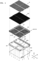
- FIG. 1 is an exploded perspective view of a battery pack according to embodiments of the present disclosure.
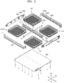
- FIG. 2 is an exploded perspective view showing a state in which inner plates 101 and 102 and outer plates 201 and 202 of FIG. 1 are being assembled to each other.
- FIG. 3 is an exploded perspective view illustrating a state in which the inner plates 101 and 102 of FIG. 1 are being assembled to each other.
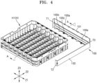
- FIG. 4 is an exploded perspective view illustrating the configuration of an inner plate unit 100 of FIG. 3 .
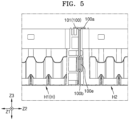
- FIG. 5 is a partial cross-sectional view of the battery pack taken along line A-A of FIG. 4 and illustrates rigid assembly between the inner plate 101 and a sub-holder H.
- FIG. 6 is an exploded perspective view illustrating a state in which the outer plates 201 and 202 of FIG. 1 are being assembled to each other.
- FIG. 7 is a partial cross-sectional view of the battery pack taken along line C-C of FIG. 6 and illustrates rigid assembly between the outer plate 201 and the sub-holder H.
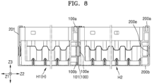
- FIG. 8 is a partial cross-sectional view of the battery pack taken along line A-A of FIG. 4 and illustrates rigid assembly between the inner plate 101, the outer plate 201, and the sub-holder H therebetween.
- FIG. 9 is an exploded perspective view illustrating coupling between the inner plates 101 and 102 and the outer plates 201 and 202.
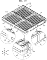
- FIG. 10 is a perspective view illustrating coupling positions W1, W2, and W3 between the inner plates 101 and 102 and the outer plates 201 and 202.
- the battery pack may include a sub-holder assembly HA including first and second sub-holders H1 and H2 arranged adjacent to each other, each accommodating a plurality of battery cells and including side portions extending in first and second directions Z1 and Z2 different from each other, an inner plate 101 (hereinafter, referred to as a first inner plate 101) and an outer plate 201 (hereinafter, a first outer plate 201) provided at an inner position and an outer position of the sub-holder assembly HA, respectively, and extending in the first direction Z1 with the first sub-holder H1 therebetween, the first inner plate 101 and the first outer plate 201 including upper locking protrusions 100a and 200a and lower locking protrusions 100b and 200b that are arranged in a third direction Z3 intersecting with the first and second directions Z1 and z2 and protrude toward the upper surface and the lower surface of the first sub-holder H1, respectively, and nut members 100c and 200c that are arranged together with the lower
- the battery pack may include the sub-holder assembly HA including the first and second sub-holders H1 and H2, each accommodating a plurality of battery cells. Also, in embodiments of the present disclosure, each of the first and second sub-holders H1 and H2 may include side portions extending in the first and second directions Z1 and Z2 different from each other.
- each of the first and second sub-holders H1 and H2 may include a pair of first side portions extending parallel to each other in the first direction Z1 with assembly positions for accommodating the plurality of battery cells therebetween and a pair of second side portions extending parallel to each other in the second direction Z2 with assembly positions for accommodating the plurality of battery cells therebetween so as to connect the pair of first side portions to each other.
- the first and second sub-holders H1 and H2 may have a substantially quadrangular box shape.
- Each of the first and second sub-holders H1 and H2 may provide cylindrical assembly positions for accommodating cylindrical battery cells.
- the sub-holder H may include at least one of an upper holder 420 and a lower holder 410 that are coupled to face each other with the plurality of battery cells therebetween.
- the sub-holder H may include only the lower holder410 as in the embodiments illustrated in the drawings.
- the sub-holder H may include only the upper holder 420 or both the upper holder 420 and the lower holder 410.
- the upper locking protrusions 100a and 200a and the lower locking protrusions 100b and 200b may protrude from the first inner plate 101 and the first outer plate 201 extending parallel to each other in the first direction Z1 with the sub-holder H therebetween toward the upper and lower surfaces of the sub-holder H.
- the sub-holder H may be located between the upper locking protrusions 100a and 200a and the lower locking protrusions 100b and 200b to thereby prevent the sub-holder H from moving in an up and down direction.
- the weight of the sub-holder H or the load acting on the sub-holder H may be transmitted to the first inner plate 101 and the first outer plate 201.
- the first inner plate 101 and the first outer plate 201 may provide rigidity to the entire battery pack.
- a feature, in which the sub-holder H is located between the first inner plate 101 and the first outer plate 201 and prevented from moving in the up and down direction by the upper locking protrusions 100a and 200a and the lower locking protrusions 100b and 200b protruding from the first inner plate 101 and the first outer plate 201 may encompass all of a feature, in which only the lower holder 410 is located, as the sub-holder H, between the upper locking protrusions 100a and 200a and the lower locking protrusions 100b and 200b of the first inner plate 101 and the first outer plate 201, and a feature, in which both the upper holder 420 and the lower holder 410 are located, as the sub-holder H, between the upper locking protrusions 100a and 200a and the lower locking protrusions 100b and 200b of the first inner plate 101 and the first outer plate 201.
- the sub-holder assembly HA may include a plurality of sub-holders H arranged in the first and second directions Z1 and Z2.
- the sub-holder assembly HA may include, as the plurality of sub-holders H, a plurality of lower holders 410 arranged in the first and second directions Z1 and Z2 or may include, as the plurality of sub-holders H, the plurality of lower holders 410 and a plurality of upper holders 420 arranged in the first and second directions Z1 and Z2.
- the sub-holder assembly HA may include the plurality of sub-holders H arranged in the first and second directions Z1 and Z2. In one or more embodiments, the first and second sub-holders H1 and H2 may be arranged in the second direction Z2. The sub-holder assembly HA may further include a third sub-holder H3 located adjacent to the first sub-holder H1 in the first direction Z1 and a fourth sub-holder H4 located adjacent to the second sub-holder H2 in the first direction Z1.
- the first to fourth sub-holders H1, H2, H3, and H4 may have substantially the same shape, and each of the first to fourth sub-holders H1, H2, H3, and H4 may include the first and second side portions extending in the first and second directions Z1 and Z2 different from each other. In one or more embodiments, the first to fourth sub-holders H1, H2, H3, and H4 may accommodate substantially the same number of battery cells.
- each of the first to fourth sub-holders H1, H2, H3, and H4 may have a substantially square box shape including the first and second side portions
- the battery pack may have a substantially square box shape including the first to fourth sub-holders H1, H2, H3, and H4 which are arranged in double rows in the first and second directions Z1 and Z2.
- the overall shape of the battery pack may have a substantially square box shape in the first and second directions Z1 and Z2, and thus, a space for mounting the battery pack may be efficiently used.
- the technical configurations applied in common to both the first and second embodiments may be explained below, without distinguishing between the one or more embodiments (first embodiments) including the first and second sub-holders H1 and H2 and the one or more embodiments (second embodiments) including the first to fourth sub-holders H1, H2, H3, and H4. Unless otherwise stated, the technical configurations described below may be applied in common to the first and second embodiments.
- embodiments of the present disclosure may selectively refer to any one of the first and second embodiments or may comprehensively refer to both the first and second embodiments.
- embodiments of the present disclosure may refer to embodiments to which the corresponding technical configurations are applied, depending on the technical configurations to be mentioned.
- different sub-holders H e.g., the first to fourth sub-holders H1, H2, H3, and H4 forming the sub-holder assembly HA may have substantially the same configuration.
- the technical configuration of one sub-holder H described below may be applied to the other sub-holders H in the same manner.
- the battery pack may include the first inner plate 101 and the first outer plate 201 arranged at the inner position and the outer position, respectively, of the sub-holder assembly HA including the first and second sub-holders H1 and H2.
- the first inner plate 101 and the first outer plate 201 may extend in the first direction Z1 with the first sub-holder H1 therebetween and may include the upper locking protrusions 100a and 200a and the lower locking protrusions 100b and 200b that are arranged in the third direction Z3 intersecting with the first and second directions Z1 and Z2 and protrude toward the upper and lower surfaces of the first sub-holder H1, respectively.
- the first inner plate 101 may extend in the first direction Z1 at the inner position of the sub-holder assembly HA and include the upper locking protrusion 100a and the lower locking protrusion 100b that are arranged in the third direction Z3 intersecting with the first and second directions Z1 and Z2 and protrude toward the upper surface and the lower surfaces of the first sub-holder H1, respectively.
- the first outer plate 201 may extend in the first direction Z1 at an outer position of the sub-holder assembly HA and include the upper locking protrusion 200a and the lower locking protrusion 200b that are arranged in the third direction Z3 and protrude toward the upper surface and the lower surfaces of the first sub-holder H1, respectively.
- a feature, in which the first inner plate 101 includes the upper locking protrusion 100a and the lower locking protrusion 100b at the inner positions of the sub-holder assembly HA may indicate that the first inner plate 101 includes the upper locking protrusion 100a and the lower locking protrusion 100b arranged at the inner positions of the sub-holder assembly HA, but may not indicate that the first inner plate 101 is entirely located at the inner position of the sub-holder assembly HA.
- an end of the first inner plate 101 may include a first bent portion T1 of the first inner plate 101, which has a wing shape, extends from a space between the first and second sub-holders H1 and H2 to out of the space between the first and second sub-holders H1 and H2, and is bent in opposite directions along the second direction Z2 to surround or extend around corners of the first and second sub-holders H1 and H2.
- the first bent portion T1 of the first inner plate 101 may be located at an outer position of the sub-holder assembly HA.
- the inner position of the sub-holder assembly HA may refer to a position that is surrounded or extended around (e.g., surrounded in a plan view by) by the sub-holder H forming the sub-holder assembly HA and the outer position of the sub-holder assembly HA may refer to a position that is not surrounded by the sub-holders H forming the sub-holder assembly HA.
- a feature, in which the first outer plate 201 includes the upper locking protrusion 200a and the lower locking protrusion 200b at the outer positions of the sub-holder assembly HA unlike the first inner plate 101, may indicate that the first outer plate 201 includes the upper locking protrusion 200a and the lower locking protrusion 200b arranged at the outer positions of the sub-holder assembly HA. Unlike the first inner plate 101, the first outer plate 201 may be entirely located at the outer position of the sub-holder assembly HA.
- the first and second sub-holders H1 and H2 may be arranged adjacent to each other in the second direction Z2, the first outer plate 201 may be provided in a pair arranged at outer positions, on opposite sides, of the first and second sub-holders H1 and H2 adjacent to each other, and the first inner plate 101 may be located at an inner position between the first and second sub-holders H1 and H2.
- first and second sub-holders H1 and H2 may be respectively arranged between the first inner plate 101 and one of the first outer plates 201 and between the first inner plate 101 and the other one of the first outer plates 201, and the first and second sub-holders H1 and H2 may be prevented from moving in the up and down direction by the upper locking protrusions 100a and 200a and the lower locking protrusions 100b and 200b that protrude toward the first and second sub-holders H1 and H2 while facing each other.
- the first inner plate 101 and the first outer plate 201 may include embossing portions 100e and 200e that match the first and second sub-holders H1 and H2 facing each other.
- the embossing portions 100e and 200e of the first inner plate 101 and the first outer plate 201 may extend in the first direction Z1 and prevent the first inner plate 101, the first outer plate 201, and the first and second sub-holders H1 and H2 from moving relative to each other in the third direction Z3 intersecting with the first and second directions Z1 and Z2.
- the side portions of the first and second sub-holders H1 and H2 facing the first inner plate 101 and the first outer plate 201 may include recessed grooves that extend in the first direction Z1 so as to match the embossing portions 100e and 200e of the first inner plate 101 and the first outer plate 201.
- the first inner plate 101 and the first outer plate 201 may include the embossing portions 100e and 200e that protrude toward the first and second sub-holders H1 and H2 so as to match the recessed grooves of the first and second sub-holders H1 and H2.
- the first inner plate 101 may be provided in a pair overlapping with each other while extending in parallel in the first direction Z1 between the first and second sub-holders H1 and H2.
- the first and second sub-holders H1 and H2 may be arranged between the lower locking protrusions 100b and the upper locking protrusions 100a protruding in both directions from the pair of first inner plates 101 overlapping with each other and may be prevented from moving in the third direction Z3 intersecting with the first and second directions Z1 and Z2.
- the first and second sub-holders H1 and H2 forming the sub-holder assembly HA may be surrounded by (e.g., surrounded in a plan view by) inner plate units 100 different from each other.
- the battery pack according to the embodiments of the present disclosure may include different inner plate units 100 respectively surrounding or extending around the central corners E of the first and second sub-holders H1 and H2.
- the inner plate units 100 respectively surrounding or extending around the first and second sub-holders H1 and H2 may include central bent portions T3 surrounding or extending around the central corners E of the first and second sub-holders H1 and H2 and first and second inner plates 101 and 102 extending from the central bent portions T3 in the first and second directions Z1 and Z2, respectively.
- each of the inner plate units 100 may include the first and second inner plates 101 and 102 that form a single body while extending from the central bent portions T3 in the first and second directions Z1 and Z2 different from each other, and each of the inner plate units 100 may be provided as a thin metal plate that is integrally formed to include the central bent portion T3.
- the central corners E of the first and second sub-holders H1 and H2 may refer to corners at inner positions surrounded by the sub-holders H forming the sub-holder assembly HA.
- the central corners E of the first and second sub-holders H1 and H2 may refer to corners at or near the central positions of the sub-holder assembly HA including a combination of the first to fourth sub-holders H1, H2, H3, and H4.
- the central corner E of one sub-holder H may be surrounded by the other sub-holders H.
- the first inner plates 101 of the different inner plate units 100 respectively surrounding or extending around the first and second sub-holders H1 and H2 may overlap with each other between the first and second sub-holders H1 and H2 while extending parallel to each other in the first direction Z1.
- the first inner plates 101 extending from a space between the first and second sub-holders H1 and H2 to out of the space between the first and second sub-holders H1 and H2 may be provided with first bent portions T1 bent in both directions to surround or extend around corners of the first and second sub-holders H1 and H2 (e.g., corners at outer positions out of the space between the first and second sub-holders H1 and H2).
- an inner plate assembly 1000 in which different inner plate units 100 surrounding or extending around the first to fourth sub-holders H1, H2, H3, and H4 are combined with each other, may have an approximately cross shape defining four divided regions in which the first to fourth sub-holders H1, H2, H3, and H4 are arranged.
- the first bent portions T1 may form ends in the first direction Z1 in the inner plate assembly 1000 having an approximately cross shape and may provide coupling positions W1 while coming into surface contact with the central positions of the second outer plates 202 extending in the second direction Z2.
- the second inner plates 102 of the different inner plate units 100 surrounding or extending around the first and second sub-holders H1 and H2 may extend in opposite directions along the second direction Z2 from the first inner plates 101 that are arranged between the first and second sub-holders H1 and H2. Also, extension ends of the second inner plates 102 extending in opposite directions along the second direction Z2 from the first inner plates 101 between the first and second sub-holders H1 and H2 may be provided with second bent portions T2 that are bent to surround or extend around corners of the first and second sub-holders H1 and H2.
- the second inner plate 102 may extend from a space between the first and third sub-holders H1 and H3 and include the second bent portion T2 that surrounds the corner (the corner of the first sub-holder H1) located at an outer position out of the space between the first and third sub-holders H1 and H3 or may extend from a space between the second and fourth sub-holders H2 and H4 and include the second bent portion T2 that surrounds the corner (the corner of the second sub-holder H2) located at an outer position out of the space between the second and fourth sub-holders H2 and H4.
- an inner plate assembly 1000 in which different inner plate units 100 surrounding or extending around the first to fourth sub-holders H1, H2, H3, and H4 are combined with each other, may have an approximately cross shape defining divided four regions in which the first to fourth sub-holders H1, H2, H3, and H4 are arranged.
- the second bent portions T2 may form ends in the second direction Z2 in the inner plate assembly 1000 having an approximately cross shape and may provide coupling positions W2 while coming into surface contact with the central positions of the first outer plates 201 extending in the first direction Z1.
- a cooling plate 500 may be disposed below the sub-holder assembly HA including the first and second sub-holders H1 and H2 or the first to fourth sub-holders H1, H2, H3, and H4 in the third direction Z3 intersecting with the first and second directions Z1 and Z2.
- a bus bar B for electrically connecting different battery cells to each other may be disposed, above the sub-holder assembly HA, on the opposite side from the cooling plate 500.
- the inner plate unit 100 may include the first and second inner plates 101 and 102 extending in the first and second directions Z1 and Z2, respectively, from the central corner E of each of the sub-holders H forming the sub-holder assembly HA so as to surround or extend around the central corner E. Also, the first and second inner plates 101 and 102 may form a height difference relative to each other in the third direction Z3. In one or more embodiments, the first and second inner plates 101 and 102 of the inner plate unit 100 may be aligned with each other at a lower position of the inner plate unit 100 adjacent to the cooling plate 500 in the third direction Z3 and form a height difference relative to each other at an upper position of the inner plate unit 100 adjacent to the bus bar B on the opposite side from the cooling plate 500.
- the height of the first inner plate 101 and the height of the first outer plate 201 may be substantially equal to the height of the sub-holder assembly HA, so that the upper locking protrusions 100a and 200a and the lower locking protrusions 100b and 200b respectively protruding from the upper and lower positions of the first inner plate 101 and the first outer plate 201 extend onto upper and lower surfaces of the sub-holder assembly HA including the first and second sub-holders H1 and H2.
- the heights of the first inner plate 101, the first outer plate 201, and the sub-holder assembly HA may be equal or substantially equal to each other.
- the second inner plate 102 may be formed differently from the first inner plate 101 and thus have the height relatively less than that of the first inner plate 101. In one or more embodiments, as the height of the second inner plate 102 is relatively lowered, the electrical connection between the sub-holders H (the first and third sub-holders H1 and H3 or the second and fourth sub-holders H2 and H4) arranged on both sides of the second inner plate 102 across the second inner plate 102 may not be interrupted by the second inner plate 102.
- the electrical connection between the sub-holders H arranged on both sides of the second inner plate 102 may be prevented from conducting electricity to the second inner plate 102.
- the first and second inner plates 101 and 102 may include a metal material, In one or more embodiments, steel, which is different from a plastic material of the sub-holder H.
- the sub-holder H may include a plastic material, considering moldability and insulation with battery cells accommodated in the sub-holder H.
- the height of the second inner plate 102 may be relatively low.
- insulation may be formed for the electrical connection between the sub-holders H on both sides of the second inner plate 102 across the second inner plate 102.
- the electrical connection may be established via the upper portion of the sub-holder assembly HA in the third direction Z3, and the cooling may be performed via the lower portion of the sub-holder assembly HA.
- the electrical connection and cooling may be made via the opposite upper and lower portions of the sub-holder assembly HA, and thus, the electrical connection of the sub-holder H may be insulated with cooling media.
- the second inner plate 102 may form a height difference with the sub-holder assembly HA or the first inner plate 101 so that the second inner plate 102 is away from the upper portion of the sub-holder assembly HA that forms the electrical connection.
- the first and second inner plates 101 and 102 may be connected to each other such that the first and second inner plates 101 and 102 are aligned with each other at the lower positions thereof and form a height difference at the upper positions thereof.
- the lower ends of the first and second inner plates 101 and 102 may be aligned with each other and the upper ends of the first and second inner plates 101 and 102 may form a height difference relative to each other.
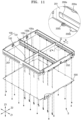
- FIG. 11 is a perspective view illustrating an assembly structure of the cooling plate 500.
- FIG. 12 is a cross-sectional view of the cooling plate 500 taken along line B-B of FIG. 11 and illustrates the assembly structure of the cooling plate 500.
- the lower locking protrusions 100b and 200b may be formed at the lower ends of the first inner plate 101 and the first outer plate 201 that extend in parallel in the first direction Z1 with the first sub-holder H1 (or the second sub-holder H2) therebetween.
- a bent piece to which each of the nut members 100c and 200c is coupled may be located, together with the lower locking protrusions 100b and 200b, on the first inner plate 101 and the first outer plate 201.
- a plurality of lower locking protrusions 100b and 200b and a plurality of bent pieces to which the nut members 100c and 200c are coupled may be arranged at positions spaced apart from each other in the first direction Z1.
- the bent piece to which each of the nut members 100c and 200c is coupled may be located between the lower locking protrusions 100b and 200b in the first direction Z1.
- the nut members 100c and 200c may be respectively coupled to the bent pieces, and
- the nut members 100c and 200c may be respectively welded and coupled to the bent pieces that are bent at the lower ends of the first inner plate 101 and the first outer plate 201.
- the fastening members S for coupling the cooling plate 500 and the sub-holder assembly HA to each other may be respectively inserted into the nut members 100c and 200c.
- the fastening members S may sequentially pass through the cooling plate 500, disposed below the sub-holder assembly HA including the first and second sub-holders H1 and H2, and the nut members 100c and 200c in the third direction Z3 intersecting with the first and second directions Z1 and Z2 and may be then accommodated in lower portions of the first and second sub-holders H1 and H2.
- accommodation spaces capable of accommodating the fastening members S may be formed in lower portions of the first and second sub-holders H1 and H2 or the first to fourth sub-holders H1, H2, H3, and H4 forming the sub-holder assembly HA.
- the sub-holder assembly HA may include the first to fourth sub-holders H1, H2, H3, and H4 that are arranged in the first and second directions Z1 and Z2.
- the sub-holder assembly HA may include the first and second sub-holders H1 and H2 adjacent to each other in the second direction Z2 and may further include the third sub-holder H3 located on the opposite side from the first sub-holder H1 in the first direction Z1, with respect to the second inner plate 102 of the inner plate unit 100 surrounding or extending around the first sub-holder H1 and the fourth sub-holder H4 located on the opposite side from the second sub-holder H2 in the first direction Z1, with respect to the second inner plate 102 of the inner plate unit 100 surrounding or extending around the second sub-holder H2.
- the first and third sub-holders H1 and H3 arranged in the first direction Z1 may be prevented from moving vertically in the third direction Z3 by the upper locking protrusions 100a and 200a and the lower locking protrusions 100b and 200b which protrude from the first outer plate 201 extending across the first and third sub-holders H1 and H3 and the different first inner plates 101 of the different inner plate units 100 respectively surrounding or extending around the first and third sub-holders H1 and H3.
- the second and fourth sub-holders H2 and H4 arranged in the first direction Z1 may be prevented from moving vertically in the third direction Z3 by the upper locking protrusions 100a and 200a and the lower locking protrusions 100b and 200b which protrude from the first outer plate 201 extending across the second and fourth sub-holders H2 and H4 and the different first inner plates 101 of the different inner plate units 100 respectively surrounding or extending around the second and fourth sub-holders H2 and H4.
- the sub-holder assembly HA may include the first to fourth inner plate units 100 respectively surrounding or extending around the central corners E of the first to fourth sub-holders H1, H2, H3, and H4.
- the first to fourth inner plate units 100 may constitute the inner plate assembly 1000 having a cross shape that defines four divided regions in which the first to fourth sub-holders H1, H2, H3, and H4 are arranged.
- the ends of the inner plate assembly 1000 in the first direction Z1 may include first bent portions T1 (one end in the first direction Z1) of first inner plates 101, having a wing shape, extending from a space between the first and second sub-holders H1 and H2 to out of the space between the first and second sub-holders H1 and H2, and bent in opposite directions along the second direction Z2 to surround or extend around corners of the first and second sub-holders H1 and H2 and other first bent portions T1 (the other end in the first direction Z1) of first inner plates 101, having a wing shape, extending from a space between the third and fourth sub-holders H3 and H4 to out of the space between the third and fourth sub-holders H3 and H4, and bent in opposite directions along the second direction Z2 to surround or extend around corners of the third and fourth sub-holders H3 and H4.
- the ends of the inner plate assembly 1000 in the second direction Z2 may include second bent portions T2 bent from both ends of the second inner plates 102 extending in opposite directions along the second direction Z2 from the first inner plates 101 between the first and second sub-holders H1 and H2, to thereby surround corners of the first and second sub-holders H1 and H2 and other second bent portions T2 bent from both ends of the second inner plates 102 extending in opposite directions along the second direction Z2 from the first inner plates 101 between the third and fourth sub-holders H3 and H4, to thereby surround corners of the third and fourth sub-holders H3 and H4.
- the second bent portions T2 and the other second bent portions T2 may have a wing shape bent in opposite directions along the first direction Z1.
- first and second bent portions T1 and T2 forming the ends of the inner plate assembly 1000 in the first and second directions Z1 and Z2 may respectively provide coupling positions Wand W2 with the second outer plates 202 extending in the second direction Z2 and the first outer plates 201 extending in the first direction Z1.
- the first outer plate 201 may be provided in a pair extending parallel to each other in the first direction Z1 at outer positions, facing each other, of the sub-holder assembly HA including the first to fourth sub-holders H1, H2, H3, and H4.
- the second outer plate 202 may be provided in a pair extending parallel to each other in the second direction Z2 at outer positions, facing each other, of the sub-holder assembly HA including the first to fourth sub-holders H1, H2, H3, and H4.
- the first and second outer plates 201 and 202 may be entirely arranged at the outer positions of the sub-holder assembly HA including the first to fourth sub-holders H1, H2, H3, and H4.
- the central position of the first outer plate 201 may establish a connection (a coupling position W2) with the second bent portion T2 forming the end of the inner plate assembly 1000 in the second direction Z2, and the central position of the second outer plate 202 may establish a connection (a coupling position W1) with the first bent portion T1 forming the end of the inner plate assembly 1000 in the first direction Z1.
- both ends of the first outer plates 201 may include coupling flanges F which are bent in the second direction Z2 to provide coupling positions with the second outer plates 202 while surrounding or extending around the corners of the sub-holder assembly HA including the first to fourth sub-holders H1, H2, H3, and H4.
- the coupling flanges F formed at both ends of the first outer plate 201 extending in the first direction Z1 may overlap with both ends of the second outer plate 202 extending in the second direction Z2.
- both ends of the second outer plate 202 and the coupling flanges F of the first outer plate 201 may be aligned with each other, so that an input/output terminal 300 electrically connected to the battery cell accommodated in the sub-holder assembly HA sequentially passes through the second outer plate 202 and the first outer plate 201 and is then exposed to the outside of the battery pack.
- both ends of the second outer plate 202 and the coupling flanges F of the first outer plate 201 may be welded around the input/output terminal 300 (a coupling position W3), and thus, both ends of the second outer plate 202 and the coupling flanges F of the first outer plate 201 may be welded and coupled to each other.
- the rigidity of the sub-holder assembly HA including the first to fourth sub-holders H1, H2, H3, and H4 may be secured (or improved) by the first inner plate 101 and the first outer plate 201 which support the sub-holder assembly HA using the upper locking protrusions 100a and 200a and the lower locking protrusions 100b and 200b at the inner positions and the outer positions of the sub-holder assembly HA.
- the sub-holder assembly HA may be located between the upper locking protrusions 100a and 200a and the lower locking protrusions 100b and 200b formed at the upper positions and the lower positions of the first inner plate 101 and the first outer plate 201 and thus prevented from moving vertically in the third direction Z3 intersecting with the first and second directions Z1 and Z2.
- the embossing portions 100e and 200e formed on the first inner plate 101 and the first outer plate 201 may match (e.g., may correspond to) recessed grooves formed in the first to fourth sub-holders H1, H2, H3, and H4 facing the first inner plate 101 and the first outer plate 201, thereby structurally integrating the first inner plate 101, the first outer plate 201, and the sub-holder assembly HA with each other.
- first and second sub-holders H1 and H2 (or the third and fourth sub-holders H3 and H4) arranged on both sides of the first inner plate 101 may be prevented from moving relative to each other.
- Deformation such as bending of the entire sub-holder assembly HA, due to the relative movement between the different first and second sub-holders H1 and H2 (or the third and fourth sub-holders H3 and H4) may be prevented. Bending or twisting due to the weight of the sub-holder assembly HA or the force or load acting on the sub-holder assembly HA may be transmitted to the first inner plate 101 and the first outer plate 201 which are integrated with the sub-holder assembly HA.
- a structure, in which the sub-holder assembly HA, the first inner plate 101, and the first outer plate 201 are physically integrated with each other may be formed by the upper locking protrusions 100a and 200a and the lower locking protrusions 100b and 200b, which are formed at the upper positions and the lower positions of the first inner plate 101 and the first outer plate 201 disposed at the inner position and the outer position of the sub-holder assembly HA including different sub-holders H.
- this structure mentioned above may be formed by matching the first inner plate 101 and the first outer plate 201 with the first to fourth sub-holders H1, H2, H3, and H4.
- the rigidity of the entire battery pack may be provided by (or may be improved by) the first inner plate 101 and the first outer plate 201 rather than the sub-holder assembly HA.
- the integrated coupling between the first inner plate 101, the first outer plate 201, and the cooling plate 500 may be formed so that sufficient rigidity is provided to the battery pack from the first inner plate 101 and the first outer plate 201.
- the fastening members S for assembling the cooling plate 500 may pass through the nut members 100c and 200c welded to the bent pieces of the first inner plate 101 and the first outer plate 201.
- the integrated coupling between the cooling plate 500, the first inner plate 101, and the first outer plate 201 may be formed by the fastening members S, so that the force or load acting on the cooling plate 500 is directly transmitted to the first inner plate 101 and the first outer plate 201.
- the fastening members S for assembling the cooling plate 500 may be inserted into the nut members 100c and 200c that have been formed in the sub-holder assembly HA by an insert molding process.
- the fastening members S may transmit the weight of the cooling plate 500 or the force or load acting on the cooling plate 500 to the nut members 100c and 200c, which are inserted and molded into the sub-holder assembly HA, rather than the first inner plate 101 and the first outer plate 201.
- the fastening members S for assembling the cooling plate 500 may be inserted into the nut members 100c and 200c that have been welded to the first inner plate 101 and the first outer plate 201.
- the fastening members S may transmit the weight of the cooling plate 500 or the force or load acting on the cooling plate 500 to the first inner plate 101 and the first outer plate 201 to which the nut members 100c and 200c are welded.
- the first inner plate 101 and the first outer plate 201 may be configured such that the weight of the sub-holder assembly HA and the cooling plate 500 or the force or load acting thereon are transmitted to the first inner plate 101 and the first outer plate 201 which provide the rigidity of the entire battery pack.
- the weight of the cooling plate 500 or the load acting on the cooling plate 500 may be directly transmitted to the sub-holders H forming the sub-holder assembly HA.
- the weight or load acting non-uniformly on the different sub-holders H forming the sub-holder assembly HA including the sub-holders H may cause movement between the sub-holders H adjacent to each other. As a result, the rigidity of the entire battery pack may be deteriorated.
- the present disclosure provides the battery pack that includes at least two sub-holders each accommodating the plurality of battery cells.
- the inner plates and the outer plates may be firmly assembled to each other while surrounding or extending around the sub-holders or the sub-holder assembly including the plurality of sub-holders to thereby prevent movement between the sub-holders different from each other and may resist the weight of the sub-holders or the sub-holder assembly or the load acting on the sub-holders or the sub-holder assembly. Therefore, the rigidity of the entire battery pack may be strengthened by the inner plates and the outer plates.
Landscapes
- Chemical & Material Sciences (AREA)
- Chemical Kinetics & Catalysis (AREA)
- Electrochemistry (AREA)
- General Chemical & Material Sciences (AREA)
- Engineering & Computer Science (AREA)
- Manufacturing & Machinery (AREA)
- Battery Mounting, Suspending (AREA)
- Secondary Cells (AREA)
Applications Claiming Priority (2)
| Application Number | Priority Date | Filing Date | Title |
|---|---|---|---|
| KR20230039406 | 2023-03-26 | ||
| KR1020230098443A KR20240144837A (ko) | 2023-03-26 | 2023-07-27 | 배터리 팩 |
Publications (2)
| Publication Number | Publication Date |
|---|---|
| EP4439756A2 true EP4439756A2 (de) | 2024-10-02 |
| EP4439756A3 EP4439756A3 (de) | 2025-04-23 |
Family
ID=90481973
Family Applications (1)
| Application Number | Title | Priority Date | Filing Date |
|---|---|---|---|
| EP24166264.2A Pending EP4439756A3 (de) | 2023-03-26 | 2024-03-26 | Batteriepack |
Country Status (2)
| Country | Link |
|---|---|
| US (1) | US20240322335A1 (de) |
| EP (1) | EP4439756A3 (de) |
Family Cites Families (3)
| Publication number | Priority date | Publication date | Assignee | Title |
|---|---|---|---|---|
| JP5595871B2 (ja) * | 2010-10-28 | 2014-09-24 | 三洋電機株式会社 | 電源装置 |
| KR102828349B1 (ko) * | 2019-09-09 | 2025-07-03 | 삼성에스디아이 주식회사 | 배터리 팩 |
| DE102022134726A1 (de) * | 2022-12-23 | 2024-07-04 | Polytec Plastics Germany Gmbh & Co. Kg | Zellträgerstrebe, Zellträgerverbundsystem sowie Batterieträger und Batteriegehäuse |
-
2024
- 2024-03-13 US US18/604,263 patent/US20240322335A1/en active Pending
- 2024-03-26 EP EP24166264.2A patent/EP4439756A3/de active Pending
Also Published As
| Publication number | Publication date |
|---|---|
| US20240322335A1 (en) | 2024-09-26 |
| EP4439756A3 (de) | 2025-04-23 |
Similar Documents
| Publication | Publication Date | Title |
|---|---|---|
| JP7037007B2 (ja) | 拡張型バッテリーモジュール構造を有するバッテリーパック | |
| EP2690684B1 (de) | Batteriezellenhalter mit verbindungszuverlässigkeit und batteriemodul damit | |
| US8859131B2 (en) | Battery module and battery pack including the same | |
| US10367180B2 (en) | Battery pack | |
| US20130236761A1 (en) | Bus bar assembly of novel structure | |
| JP2018006314A (ja) | 電池サブモジュールキャリア、電池サブモジュール、電池システムおよび自動車 | |
| KR101750487B1 (ko) | 외부 입출력 단자 및 버스 바의 장착 수단을 포함하는 전지모듈 | |
| KR20120048280A (ko) | 전지 모듈 | |
| US9331316B2 (en) | Battery cell holder | |
| KR102903479B1 (ko) | 배터리 팩 | |
| US12015172B2 (en) | Battery pack including connection plate, electronic device and vehicle | |
| JP2021532563A (ja) | バッテリーパック及びそれを含む自動車 | |
| KR102771719B1 (ko) | 전지팩 | |
| EP4447218A1 (de) | Wiederaufladbares batteriemodul | |
| EP3699980B1 (de) | Batteriepack | |
| KR102416817B1 (ko) | 배터리 팩의 외함, 이를 이용한 배터리 팩 및 자동차 | |
| EP4439756A2 (de) | Batteriepack | |
| US20250286201A1 (en) | Electricity storage device | |
| CN118712600A (zh) | 电池组 | |
| US20240347870A1 (en) | Rechargeable battery module | |
| KR102834381B1 (ko) | 배터리팩의 직병렬 용량 증설시 연결 및 지지 편의성을 향상시킨 배터리팩 케이스 결합 구조 | |
| KR20240144837A (ko) | 배터리 팩 | |
| KR20250126453A (ko) | 배터리팩의 직병렬 용량 증설시 연결 편의성을 향상시킨 버스바 연결 구조 | |
| KR20250040390A (ko) | 배터리 팩 및 이를 포함하는 자동차 | |
| KR20250101718A (ko) | 배터리 팩 |
Legal Events
| Date | Code | Title | Description |
|---|---|---|---|
| PUAI | Public reference made under article 153(3) epc to a published international application that has entered the european phase |
Free format text: ORIGINAL CODE: 0009012 |
|
| STAA | Information on the status of an ep patent application or granted ep patent |
Free format text: STATUS: REQUEST FOR EXAMINATION WAS MADE |
|
| 17P | Request for examination filed |
Effective date: 20240326 |
|
| AK | Designated contracting states |
Kind code of ref document: A2 Designated state(s): AL AT BE BG CH CY CZ DE DK EE ES FI FR GB GR HR HU IE IS IT LI LT LU LV MC ME MK MT NL NO PL PT RO RS SE SI SK SM TR |
|
| RIC1 | Information provided on ipc code assigned before grant |
Ipc: H01M 50/291 20210101ALI20241126BHEP Ipc: H01M 50/244 20210101ALI20241126BHEP Ipc: H01M 50/264 20210101ALI20241126BHEP Ipc: H01M 50/262 20210101ALI20241126BHEP Ipc: H01M 50/209 20210101ALI20241126BHEP Ipc: H01M 10/6557 20140101ALI20241126BHEP Ipc: H01M 10/6556 20140101ALI20241126BHEP Ipc: H01M 10/6554 20140101ALI20241126BHEP Ipc: H01M 10/647 20140101ALI20241126BHEP Ipc: H01M 10/625 20140101ALI20241126BHEP Ipc: H01M 10/613 20140101ALI20241126BHEP Ipc: H01M 10/04 20060101AFI20241126BHEP |
|
| PUAL | Search report despatched |
Free format text: ORIGINAL CODE: 0009013 |
|
| AK | Designated contracting states |
Kind code of ref document: A3 Designated state(s): AL AT BE BG CH CY CZ DE DK EE ES FI FR GB GR HR HU IE IS IT LI LT LU LV MC ME MK MT NL NO PL PT RO RS SE SI SK SM TR |
|
| RIC1 | Information provided on ipc code assigned before grant |
Ipc: H01M 50/291 20210101ALI20250318BHEP Ipc: H01M 50/244 20210101ALI20250318BHEP Ipc: H01M 50/264 20210101ALI20250318BHEP Ipc: H01M 50/262 20210101ALI20250318BHEP Ipc: H01M 50/209 20210101ALI20250318BHEP Ipc: H01M 10/6557 20140101ALI20250318BHEP Ipc: H01M 10/6556 20140101ALI20250318BHEP Ipc: H01M 10/6554 20140101ALI20250318BHEP Ipc: H01M 10/647 20140101ALI20250318BHEP Ipc: H01M 10/625 20140101ALI20250318BHEP Ipc: H01M 10/613 20140101ALI20250318BHEP Ipc: H01M 10/04 20060101AFI20250318BHEP |