EP4439747A1 - Apparatus for producing multilayer body for secondary batteries - Google Patents
Apparatus for producing multilayer body for secondary batteries Download PDFInfo
- Publication number
- EP4439747A1 EP4439747A1 EP21963276.7A EP21963276A EP4439747A1 EP 4439747 A1 EP4439747 A1 EP 4439747A1 EP 21963276 A EP21963276 A EP 21963276A EP 4439747 A1 EP4439747 A1 EP 4439747A1
- Authority
- EP
- European Patent Office
- Prior art keywords
- separator
- electrode sheet
- stack
- transfer
- standby position
- Prior art date
- Legal status (The legal status is an assumption and is not a legal conclusion. Google has not performed a legal analysis and makes no representation as to the accuracy of the status listed.)
- Pending
Links
Images


Classifications
-
- H—ELECTRICITY
- H01—ELECTRIC ELEMENTS
- H01M—PROCESSES OR MEANS, e.g. BATTERIES, FOR THE DIRECT CONVERSION OF CHEMICAL ENERGY INTO ELECTRICAL ENERGY
- H01M10/00—Secondary cells; Manufacture thereof
- H01M10/04—Construction or manufacture in general
- H01M10/0404—Machines for assembling batteries
-
- H—ELECTRICITY
- H01—ELECTRIC ELEMENTS
- H01M—PROCESSES OR MEANS, e.g. BATTERIES, FOR THE DIRECT CONVERSION OF CHEMICAL ENERGY INTO ELECTRICAL ENERGY
- H01M10/00—Secondary cells; Manufacture thereof
- H01M10/04—Construction or manufacture in general
- H01M10/0459—Cells or batteries with folded separator between plate-like electrodes
-
- H—ELECTRICITY
- H01—ELECTRIC ELEMENTS
- H01M—PROCESSES OR MEANS, e.g. BATTERIES, FOR THE DIRECT CONVERSION OF CHEMICAL ENERGY INTO ELECTRICAL ENERGY
- H01M10/00—Secondary cells; Manufacture thereof
- H01M10/05—Accumulators with non-aqueous electrolyte
- H01M10/058—Construction or manufacture
- H01M10/0583—Construction or manufacture of accumulators with folded construction elements except wound ones, i.e. folded positive or negative electrodes or separators, e.g. with "Z"-shaped electrodes or separators
-
- H—ELECTRICITY
- H01—ELECTRIC ELEMENTS
- H01M—PROCESSES OR MEANS, e.g. BATTERIES, FOR THE DIRECT CONVERSION OF CHEMICAL ENERGY INTO ELECTRICAL ENERGY
- H01M10/00—Secondary cells; Manufacture thereof
- H01M10/04—Construction or manufacture in general
- H01M10/0413—Large-sized flat cells or batteries for motive or stationary systems with plate-like electrodes
-
- H—ELECTRICITY
- H01—ELECTRIC ELEMENTS
- H01M—PROCESSES OR MEANS, e.g. BATTERIES, FOR THE DIRECT CONVERSION OF CHEMICAL ENERGY INTO ELECTRICAL ENERGY
- H01M50/00—Constructional details or processes of manufacture of the non-active parts of electrochemical cells other than fuel cells, e.g. hybrid cells
- H01M50/40—Separators; Membranes; Diaphragms; Spacing elements inside cells
- H01M50/463—Separators, membranes or diaphragms characterised by their shape
- H01M50/466—U-shaped, bag-shaped or folded
-
- Y—GENERAL TAGGING OF NEW TECHNOLOGICAL DEVELOPMENTS; GENERAL TAGGING OF CROSS-SECTIONAL TECHNOLOGIES SPANNING OVER SEVERAL SECTIONS OF THE IPC; TECHNICAL SUBJECTS COVERED BY FORMER USPC CROSS-REFERENCE ART COLLECTIONS [XRACs] AND DIGESTS
- Y02—TECHNOLOGIES OR APPLICATIONS FOR MITIGATION OR ADAPTATION AGAINST CLIMATE CHANGE
- Y02E—REDUCTION OF GREENHOUSE GAS [GHG] EMISSIONS, RELATED TO ENERGY GENERATION, TRANSMISSION OR DISTRIBUTION
- Y02E60/00—Enabling technologies; Technologies with a potential or indirect contribution to GHG emissions mitigation
- Y02E60/10—Energy storage using batteries
-
- Y—GENERAL TAGGING OF NEW TECHNOLOGICAL DEVELOPMENTS; GENERAL TAGGING OF CROSS-SECTIONAL TECHNOLOGIES SPANNING OVER SEVERAL SECTIONS OF THE IPC; TECHNICAL SUBJECTS COVERED BY FORMER USPC CROSS-REFERENCE ART COLLECTIONS [XRACs] AND DIGESTS
- Y02—TECHNOLOGIES OR APPLICATIONS FOR MITIGATION OR ADAPTATION AGAINST CLIMATE CHANGE
- Y02P—CLIMATE CHANGE MITIGATION TECHNOLOGIES IN THE PRODUCTION OR PROCESSING OF GOODS
- Y02P70/00—Climate change mitigation technologies in the production process for final industrial or consumer products
- Y02P70/50—Manufacturing or production processes characterised by the final manufactured product
Definitions
- the present invention relates to an apparatus for manufacturing a stack for a secondary battery, the stack including a separator folded in a zigzag manner that is interposed between electrode sheets, and more particularly to an apparatus capable of forming the stack stably and at high speed.
- the stack includes positive electrode sheets and negative electrode sheets which are alternately stacked with a separator interposed therebetween.
- a technology using a band-shaped separator involves:
- the positive electrode sheets and the negative electrode sheets are alternately transferred with use of, for example, one arm. Thus, there is a problem in that high-speed placement is difficult.
- the separator is moved in a reciprocating manner above a placement location.
- a volume practically occupied by a reciprocating mechanism increases.
- high-speed driving is difficult to perform because interference with the arm is to be avoided, and in addition, a degree of freedom in design of a system is decreased.
- the present invention has been made in view of the problems described above, and has an object to provide a technology for manufacturing a stack for a secondary battery at high speed.
- an apparatus for manufacturing a stack for a secondary battery including a band-shaped separator elongated in one direction, which is folded in a zigzag manner, and electrode sheets A and electrode sheets B, each basically being a rectangular flat sheet, which are stacked alternately while the separator is interposed therebetween, the folding in the zigzag manner having a folding-line direction being a band width direction
- the apparatus including: first transfer means configured to transfer the electrode sheets A in order onto a placement table with the electrode sheets A oriented in the same orientation direction; arrangement means configured to arrange the electrode sheet B at a standby position with sides of the electrode sheet B being aligned in parallel to sides of the electrode sheet A placed on the placement table, which extend in the folding-line direction; separator supply means configured to extend the separator from a feeding source, cause the separator to pass directly above the electrode sheet B being at the standby position, and supply the separator without slack to a stack on the placement table, the stack being a feeding destination; second transfer means configured to transfer the electrode sheets A
- the separator can be folded in a Z-shape so as to be interposed between the electrode sheet B and the electrode sheet A in order while being pulled out through transfer movement for the electrode sheets B.
- the stack can be manufactured at high speed.
- the electrode sheet A and the electrode sheet B are electrode sheets which are provided such that one of the electrode sheet A and the electrode sheet B is a positive electrode sheet and another one thereof is a negative electrode sheet. Both of the electrode sheets have substantially the same shape. However, the negative electrode sheet may be larger than the positive electrode sheet. As for the separator, its length in the folding-line direction may be larger than those of the electrode sheets so as to increase insulation reliability.
- the predetermined length is a length that allows achievement of folding in a zigzag manner and is substantially equal to a width of the electrode sheet A or the electrode sheet B. It is preferred that the predetermined length be a length with an appropriate margin for folding.
- a way of holding with the holders is not limited to any particular one as long as the electrode sheet B and the separator can be held together, and examples of holding include pinching. Besides, suction can also be used when the separator is porous.
- the holders perform holding and releasing.
- the holding and releasing may be appropriately accompanied by an operation such as pullout or insertion so as to avoid interference with the stack or the like.
- an apparatus for manufacturing a stack for a secondary battery including a band-shaped separator elongated in one direction, which is folded in a zigzag manner, and electrode sheets A and electrode sheets B, each basically being a rectangular flat sheet, which are stacked alternately while the separator is interposed therebetween, the folding in the zigzag manner having a folding-line direction being a band width direction
- the apparatus including: a placement table on which formation of the stack is performed; arrangement means configured to arrange the electrode sheet B at a standby position with sides of the electrode sheet B being aligned in parallel to sides of the stack on the placement table, which extend in the folding-line direction; separator supply means configured to extend the separator from a feeding source, cause the separator to pass directly above the electrode sheet B being at the standby position, and supply the separator without slack to the stack on the placement table, the stack being a feeding destination; first transfer means configured to transfer the electrode sheet A onto the electrode sheet B being at the standby position so that
- the electrode sheet B and the electrode sheet A are transferred together.
- the separator interposed therebetween can be folded in a Z-shape so as to be stacked in order onto the placement table while being pulled out.
- the stack can be manufactured at high speed.
- the apparatus for manufacturing a stack for a secondary battery further includes lowering means configured to lower the placement table in a step-by-step manner along with the transfer so that a height of an uppermost surface on the placement table is kept constant.
- the stack can be stably manufactured without causing a positional shift due to stacking.
- the lowering includes, besides dynamic lowering of the placement table itself, passive downward movement as a result of downward pushing occurring along with the transfer.
- the transfer means may also serve as the lowering means depending on a mode of use.
- the uppermost electrode sheet on the placement table and the electrode sheet at the standby position are aligned in height so as to be positioned at practically the same height
- the second transfer means includes: two bifurcated arms opposed to each other, each having an axially rotatable proximal end and arm distal ends implanted with the holders, respectively, the bifurcated arms having rotary shafts that are aligned with each other so as to extend on the same straight line in the folding-line direction; drive means configured to axially rotate the bifurcated arms; opening and closing control means configured to control the holders to alternately perform holding and releasing for each half revolution.
- transfer and return are achieved through rotational driving with alignment of phases and positions to thereby achieve stable high-speed manufacture.
- the wording "practically the same height” means that, in the case of the apparatus of claim 1, the uppermost electrode sheet A on the placement table and the electrode sheet B at the standby position are located at substantially the same height, and in the case of the apparatus of claim 2, the uppermost electrode sheet A on the placement table and the electrode sheet A at the standby position are located at substantially the same height.
- the bifurcated arm is defined broadly and is not limited to any particular one as long as the transfer is performed twice while the rotary shaft is making one revolution with circular movement of the two holders.
- Examples of the bifurcated arm include not only a bifurcated arm that is rotationally symmetric through 180 degrees but also a bifurcated arm having disc surfaces on which two holders are mounted.
- a phase cancellation mechanism for allowing the holder to perform axial rotation in a direction opposite to axial rotation of the arm so as to prevent the orientation of the electrode sheets from being changed. Further, a distance between the two holders provided at the distal ends of the arm is set so as to allow the Z-folding (a distance between centers of the holders is set about twice as large as the width of the electrode sheets).
- the separator supply means includes: a cylindrical body having an axis extending in the folding-line direction, which is arranged on a side opposite to the placement table when viewed from the standby position and is to be brought into contact with the separator so as to cause the separator to pass directly above the electrode sheet B; and reciprocating means configured to substantially horizontally move the cylindrical body forward and backward without changing a direction of the axis of the cylindrical body so as to reduce a fluctuation in tension of the separator, which occurs at the time of the transfer performed by the second transfer means.
- a feeding speed for the separator can be kept constant or be set to fall within a given range to thereby achieve stable manufacture at high speed.
- the separator is supplied from a position appropriately higher than the cylindrical body, is brought into contact with a lower part of the cylindrical body by a length corresponding to a central angle of about 90 degrees, is reoriented horizontally, and is caused to pass directly above the standby position.
- substantially horizontally means that displacement in a vertical direction may be appropriately included so as to avoid interference or the like.
- the present invention can provide a technology for manufacturing a stack for a secondary battery at high speed.
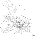
- FIG. 1 is a schematic perspective view of an apparatus for manufacturing a stack for a secondary battery.
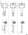
- FIGS. 2 and FIGS. 3 are explanatory views (left side views on the left side and plan views on the right side) for illustrating a sequence of operations.
- a configuration or a way of drawing is appropriately simplified for convenience of description.
- stack manufacturing apparatus the apparatus for manufacturing a stack for a secondary battery is appropriately referred to simply as "stack manufacturing apparatus".
- a stack manufacturing apparatus that forms a stack in the following manner.
- a negative electrode sheet is first placed on a placement table.
- a positive electrode sheet is transferred onto the negative electrode sheet while a separator is being folded thereunder to form a stack.
- the stack manufacturing apparatus 1 includes, as main components, a negative electrode sheet supply unit 10, a positive electrode sheet supply unit 20, a separator supply unit 30, a stacking unit 40, and a sequence control unit 50.
- the stack manufacturing apparatus 1 manufactures a stack 2 including a separator S having a band-like shape folded in a zigzag manner, and a negative electrode sheet 91 and a positive electrode sheet 92.
- the negative electrode sheet 91 and the positive electrode sheet 92 are alternately stacked while the separator S is interposed therebetween.
- the negative electrode sheet 91 is a thin copper sheet basically having a rectangular shape and has a tongue piece 91z formed at a position shifted from a center of a short side of the rectangle.
- the positive electrode sheet 92 is a thin aluminum sheet also basically having a rectangular shape and has a tongue piece 92z formed at a position shifted from a center of a short side of the rectangle.
- the negative electrode sheet 91 is larger than the positive electrode sheet 92.
- a thin copper sheet having a length of 146 mm, a breadth (width) of 96 mm, and a thickness of 0.02 mm is used as the negative electrode sheet 91
- a thin aluminum sheet having a length of 142 mm, a breadth (width) of 92 mm, and a thickness of 0.02 mm is used as the positive electrode sheet 92.
- the negative electrode sheet 91 and the positive electrode sheet 92 are appropriately referred to as “electrode sheets 90" when the negative electrode sheet 91 and the positive electrode sheet 92 are not required to be distinguished from each other.
- the width of the separator S is set longer than the longitudinal length of the negative electrode sheet 91 so as to prevent short-circuiting.
- the separator S may have a width of 150 mm and a thickness of 0.02 mm. In some drawings, however, the width of the separator S is illustrated as being shorter than the electrode sheets 90 for convenience of the description.
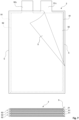
- FIG. 7 includes a plan view and a front view, in which the stack 2 is illustrated with a ratio close to an actual one.
- the negative electrode sheet supply unit 10 includes an endless conveyor 11 and a transfer robot 12.
- the endless conveyor 11 intermittently conveys the negative electrode sheets 91 at equal intervals with the negative electrode sheets 91 oriented in the same direction.
- the transfer robot 12 repeats an operation of attracting the negative electrode sheet 91 arriving at a most downstream position on the endless conveyor 11 from directly above, transferring the negative electrode sheet 91 onto a placement table 41 of the stacking unit 40, and releasing the negative electrode sheet 91.
- the positive electrode sheet supply unit 20 includes an endless conveyor 21.
- the endless conveyor 21 intermittently transfers the positive electrode sheets 92 at equal intervals with the positive electrode sheets 92 oriented in the same direction.
- the separator supply unit 30 includes a separator roll 31, an orientation roller group 32, a dancer roller 33, and a reciprocating drive unit 34.
- the separator roll 31 is formed by winding the separator S having a band-like shape elongated in one direction around a shaft 31a.
- the orientation roller group 32 passes the separator S, which has been fed from the separator roll 31, to the vicinity of a downstream side of the endless conveyor 21 while appropriately changing a direction in which the separator S is conveyed.
- the dancer roller 33 has a cylindrical shape and is positioned above the vicinity of the most downstream side of the endless conveyor 21.
- a last orientation roller 32f of the orientation roller group 32 is provided at a position higher than the dancer roller 33 so as to supply the separator S from above the dancer roller 33.
- the separator S that has been supplied from above is brought into contact with a lower part of a peripheral surface of the dancer roller 33 so that the separator S is reoriented substantially horizontally. In this manner, the separator S is caused to pass directly above the positive electrode sheet 92 being at a standby position 424 described later.
- the shaft 31a of the separator roll 31 is arranged horizontally. Although the separator S moves up and down until the separator S reaches the stack 2, the separator S is fed without being moved in a lateral direction, i.e., a direction of the shaft 31a (this direction is also a width direction of the separator S) and, in this sense, is fed linearly when viewed from the separator roll 31.
- the separator S is folded in a zigzag manner.
- a folding-line direction of the zigzag folding is the same as (parallel to) the direction of the shaft 31a described above or the width direction of the separator S.
- a shaft 33a of the dancer roller 33 and shafts of the orientation roller group 32 also extend in parallel to the folding-line direction.
- the reciprocating drive unit 34 reciprocates above the endless conveyor 21 while holding the shaft 33a of the dancer roller 33 so as not to change an orientation of the shaft 33a.
- the separator S is stretched without slack from the separator roll 31 corresponding to a feeding source to the stack 2 corresponding to a feeding destination.
- the reciprocating drive unit 34 absorbs or alleviates the tension fluctuation so as to prevent a tear in the separator S or excessive feeding due to inertia of the separator roll 31. Reciprocating movement is described later.
- the stacking unit 40 includes the placement table 41 and a rotary chuck mechanism 43.
- the placement table 41 includes a seat 411, holding claws 412, and a downward driving unit 413.
- the seat 411 is a place where the stack 2 is formed.
- the positive electrode sheets 92 and the negative electrode sheets 91 are alternately stacked while the separator S folded in the zigzag manner is interposed therebetween.
- the negative electrode sheets 91 are stacked by the transfer robot 12, and the positive electrode sheets 92 are stacked while the separator S is being folded thereunder by the rotary chuck mechanism 93.
- Both of the positive electrode sheets 92 and the negative electrode sheets 91 are arranged so that their long sides extend in the folding-line direction.
- the holding claws 412 are L-shaped claws that hold down the stack 2 while regulating side surfaces of the stack 2 so as to prevent an uppermost negative electrode sheet 91 on the seat 411 from being moved. After the negative electrode sheet 91 is transferred from the transfer robot 12, the holding claws 412 are temporarily pulled out from the stack 2 and then hold down the uppermost negative electrode sheet 91 again. After that, the separator S and the positive electrode sheet 92 are stacked in a bundle on the negative electrode sheet 91. The holding claws 412 remain in the same state until a next negative electrode sheet 91 is transferred from the transfer robot 12.
- the downward driving unit 413 performs lowering the seat 411 in a step-by-step manner each time the negative electrode sheet 91 is stacked so that the uppermost negative electrode sheet 91 on the seat 411 is aligned with the standby position 424 in height.
- a lowering interval corresponds to a total thickness of one negative electrode sheet 91, one positive electrode sheet 92, and two separators.
- the rotary chuck mechanism 43 picks up the positive electrode sheet 92 arriving at the most downstream position on the endless conveyor 21 and stacks the positive electrode sheet 92 on the placement table 41.
- the most downstream position is referred to as "standby position 424".
- a distance between the positive electrode sheet 92 at the standby position 424 and the negative electrode sheet 91 on the seat 411 is designed so as to be equal to: the width (length of a short side) of the negative electrode sheet 91 + ⁇ .
- a positional relationship is determined so that a length of a free part of the separator S, which extends between the positive electrode sheet 92 at the standby position 424 and the negative electrode sheet 91 on the seat 411, is substantially equal to a width of (length of a short side) of the electrode sheet 90.
- the rotary chuck mechanism 43 includes a pair of bifurcated arms 431, two sets of opening and closing chucks 432, drive motors 433, and a chuck control unit 434.
- Each of the bifurcated arms 431 includes an arm 431b.
- the arm 431b rotates about a shaft 431a and is bifurcated in the middle.
- the opening and closing chucks 432 are implanted in two distal ends of the bifurcated arm 431, respectively.
- the shafts 431a extend on the same straight line in the folding-line direction at the same height as the standby position 424 and an uppermost surface on the seat 411 and are positioned in the middle between the standby position 424 and the seat 411.
- Phases of the opening and closing chucks 432 facing each other are aligned. Specifically, the opening and closing chuck 432 is set at the same height as a height of the opening and closing chuck 432 opposed thereto.
- the chuck control unit 434 closes two opposed opening and closing chucks 432 (folds down upper flaps thereof) that are located at the standby position 424 and controls the opening and closing chucks 432 to grip the positive electrode sheet 92 and the separator S lying directly thereon so that short sides of the positive electrode sheet 92 and end sides of the separator S are aligned with each other.
- two opposed opening and closing chucks 432 that are located on the uppermost surface on the seat 411 are controlled to be released from pressure and pulled out so as to complete the transfer of the positive electrode sheet 92 onto the seat 411. Their upper flaps are turned up before a next half revolution.
- the opening and closing chucks 432 grip and transfer the positive electrode sheet 92 with an upper surface of the positive electrode sheet 92 always facing upward.
- the sequence control unit 50 controls overall driving so that the positive electrode sheets 92 and the negative electrode sheets 91 are transferred alternately.
- the endless conveyor 11, the transfer robot 12, and the endless conveyor 21 are intermittently driven in synchronization.
- the sequence control unit 50 controls the drive motors 433, the chuck control unit 434, the reciprocating drive unit 34, the downward driving unit 413, and the like at the same time intervals as those of the intermittent driving to thereby form the stack 2 in order.
- the transfer robot 12 transfers the negative electrode sheet 91 onto the seat 411 ( FIG. 2a ).
- the dancer roller 33 is moved back toward the positive electrode sheet supply unit 20 (moved to an upstream side of the endless conveyor 21).
- the holding claws 412 are pulled out from the stack 2 and are raised for next holding ( FIG. 2b ). Further, the opening and closing chucks 432 on the seat 411 side are slid simultaneously with the release of pressure from their upper flaps and are pulled out from the stack 2. At this time, the separator S and the stack 2 are being held by the transfer robot 12, and thus posture stability is maintained.
- the upper flaps of the opening and closing chucks 432 on the standby position 424 side are closed, and the opening and closing chucks 432 grip the separator S and the positive electrode sheet 92 together.
- the holding claws 412 start holding down the uppermost negative electrode sheet 91 again, and the downward driving unit 413 lowers the seat 411 by one step ( FIG. 2c ) . Further, the upper flaps of the opening and closing chucks 432 on the seat 411 side are turned up. Meanwhile, the transfer robot 12 is continuously holding the separator S and the stack 2 so as to keep their postures.
- the sequence control unit 50 controls the reciprocating drive unit 34 in synchronization with the rotation of the bifurcated arms 431.
- an excessive increase in tension of the separator S is reduced to prevent a tear in the separator S and excessive rotation of the separator roll 31.
- the forward movement and the backward movement of the dancer roller 33 are controlled so as to prevent a tear and excessive rotation.
- a stack manufacturing apparatus that superposes a negative electrode sheet on a positive electrode sheet which is overlaid by a separator and transfers these three elements together onto a placement table to form a stack.
- a sequence control unit 50 controls overall driving so that the transfer of the negative electrode sheet 91 and the transfer of a bundle of the negative electrode sheet 91, the separator S, and the positive electrode sheet 92 onto the seat 411 alternate with each other.
- the holding claws 412 holding down the stack 2 are pulled out therefrom and are raised so as to prepare for next holding.
- a dancer roller 33 is moved back toward a positive electrode sheet supply unit 20.
- the holding claws 412 hold down an uppermost negative electrode sheet 91 again ( FIG. 5b ). At this time, even after the holding claws 412 are pulled out from the stack 2, a posture of the stack 2 does not change because the opening and closing chucks 432 on the seat 411 side are holding the stack 2.
- the dancer roller 33 is continuously moved back toward the positive electrode sheet supply unit 20.
- the opening and closing chucks 432 on the seat 411 side are slid to be pulled out from the stack 2 ( FIG. 5c ).
- the posture of the stack 2 does not change because the holding claws 412 are now holding down the uppermost negative electrode sheet 91.
- the bifurcated arms 431 are rotated to superpose a bundle of the negative electrode sheet 91, the separator S, and the positive electrode sheet 92, which is held in the opening and closing chucks 423 in a sandwiched manner, on the uppermost negative electrode sheet 91 on the seat 411 (FIG. 6a, FIG. 6e ).
- the dancer roller 33 is moved forward and the downward driving unit 413 lowers the seat 411 by one step in synchronization with the rotation of the bifurcated arms 431.
- endless conveyor 21 is driven to convey a next positive electrode sheet 92 to the standby position 424.
- the sequence control unit 50 controls the reciprocating drive unit 34 in synchronization with the rotation of the bifurcated arms 431.
- an excessive increase in tension of the separator S is reduced to prevent a tear in the separator S and excessive rotation of the separator roll 31.
- the forward movement and the backward movement of the dancer roller 33 are controlled so as to prevent a tear and excessive rotation.
- the rotary chuck mechanism 43 enables folding of the separator S in a zigzag manner simultaneously with the transfer of a set of the electrode sheets 90 so that the separator S is provided in the stack 2 in a sandwiched manner.
- the stack 2 can be manufactured at high speed with the alignment of the phases.
- the application of the present invention also enables manufacture of a capacitor.
Landscapes
- Chemical & Material Sciences (AREA)
- Chemical Kinetics & Catalysis (AREA)
- Electrochemistry (AREA)
- General Chemical & Material Sciences (AREA)
- Engineering & Computer Science (AREA)
- Manufacturing & Machinery (AREA)
- Secondary Cells (AREA)
Abstract
Description
- The present invention relates to an apparatus for manufacturing a stack for a secondary battery, the stack including a separator folded in a zigzag manner that is interposed between electrode sheets, and more particularly to an apparatus capable of forming the stack stably and at high speed.
- For manufacture of a secondary battery, a stack is formed. The stack includes positive electrode sheets and negative electrode sheets which are alternately stacked with a separator interposed therebetween.
- For example, a technology using a band-shaped separator involves:
- 1) placing a positive electrode sheet,
- 2) moving a supply roller for a separator from a left side to a right side of the positive electrode sheet so that the separator is extended in a width direction of the positive electrode sheet to cover the positive electrode sheet,
- 3) placing a negative electrode sheet on the separator,
- 4) moving the supply roller for the separator from a right side to a left side of the negative electrode sheet so that the separator is extended in a width direction of the negative electrode sheet to cover the negative electrode sheet,
- 1) placing another positive electrode sheet on the separator, and so on. The steps 1) to 4) are repeated to form a stack.
- However, the related-art technology has the following problems.
- The positive electrode sheets and the negative electrode sheets are alternately transferred with use of, for example, one arm. Thus, there is a problem in that high-speed placement is difficult.
- Further, the separator is moved in a reciprocating manner above a placement location. Thus, a volume practically occupied by a reciprocating mechanism increases. Hence, there are also other problems in that high-speed driving is difficult to perform because interference with the arm is to be avoided, and in addition, a degree of freedom in design of a system is decreased.
- Further, even when high-speed driving is achieved, reciprocation is intermittently performed. Thus, there is a problem in that excessive rotation of a separator roll at a proximal end may cause slack.
-
- [PTL 1]
JP 2004-022449 A - [PTL 2]
JP 2017-016946 A - The present invention has been made in view of the problems described above, and has an object to provide a technology for manufacturing a stack for a secondary battery at high speed.
- According to
claim 1, there is provided an apparatus for manufacturing a stack for a secondary battery, the stack including a band-shaped separator elongated in one direction, which is folded in a zigzag manner, and electrode sheets A and electrode sheets B, each basically being a rectangular flat sheet, which are stacked alternately while the separator is interposed therebetween, the folding in the zigzag manner having a folding-line direction being a band width direction, the apparatus including: first transfer means configured to transfer the electrode sheets A in order onto a placement table with the electrode sheets A oriented in the same orientation direction; arrangement means configured to arrange the electrode sheet B at a standby position with sides of the electrode sheet B being aligned in parallel to sides of the electrode sheet A placed on the placement table, which extend in the folding-line direction; separator supply means configured to extend the separator from a feeding source, cause the separator to pass directly above the electrode sheet B being at the standby position, and supply the separator without slack to a stack on the placement table, the stack being a feeding destination; second transfer means, which includes two holders arranged so as to be opposed to each other in the folding-line direction and is configured to hold the electrode sheet B being at the standby position and the separator thereabove together so that a free part of the separator, which extends between the electrode sheet B being at the standby position and an uppermost one of the electrode sheets A being at a placement position, has a predetermined length and transfer the electrode sheet B and the separator onto the uppermost electrode sheet A on the placement table in order; and transfer control means configured to control a transfer order so that the transfer performed by the first transfer means and the transfer performed by the second transfer means alternate with each other. - Specifically, according to the invention of
claim 1, the separator can be folded in a Z-shape so as to be interposed between the electrode sheet B and the electrode sheet A in order while being pulled out through transfer movement for the electrode sheets B. Thus, the stack can be manufactured at high speed. - The electrode sheet A and the electrode sheet B are electrode sheets which are provided such that one of the electrode sheet A and the electrode sheet B is a positive electrode sheet and another one thereof is a negative electrode sheet. Both of the electrode sheets have substantially the same shape. However, the negative electrode sheet may be larger than the positive electrode sheet. As for the separator, its length in the folding-line direction may be larger than those of the electrode sheets so as to increase insulation reliability.
- It is apparent that the predetermined length is a length that allows achievement of folding in a zigzag manner and is substantially equal to a width of the electrode sheet A or the electrode sheet B. It is preferred that the predetermined length be a length with an appropriate margin for folding.
- A way of holding with the holders is not limited to any particular one as long as the electrode sheet B and the separator can be held together, and examples of holding include pinching. Besides, suction can also be used when the separator is porous.
- Further, the holders perform holding and releasing. However, the holding and releasing may be appropriately accompanied by an operation such as pullout or insertion so as to avoid interference with the stack or the like.
- According to
claim 2, there is provided an apparatus for manufacturing a stack for a secondary battery, the stack including a band-shaped separator elongated in one direction, which is folded in a zigzag manner, and electrode sheets A and electrode sheets B, each basically being a rectangular flat sheet, which are stacked alternately while the separator is interposed therebetween, the folding in the zigzag manner having a folding-line direction being a band width direction, the apparatus including: a placement table on which formation of the stack is performed; arrangement means configured to arrange the electrode sheet B at a standby position with sides of the electrode sheet B being aligned in parallel to sides of the stack on the placement table, which extend in the folding-line direction; separator supply means configured to extend the separator from a feeding source, cause the separator to pass directly above the electrode sheet B being at the standby position, and supply the separator without slack to the stack on the placement table, the stack being a feeding destination; first transfer means configured to transfer the electrode sheet A onto the electrode sheet B being at the standby position so that the separator is interposed between the electrode sheet B and the electrode sheet A with the electrode sheet B and the electrode sheet A oriented in the same orientation direction; second transfer means, which includes two holders arranged so as to be opposed to each other in the folding-line direction and is configured to hold the electrode sheet B, the separator, and the electrode sheet A together, each being at the standby position, with the holders so that a free part of the separator, which extends between the electrode sheet B being at the standby position and an uppermost one of the electrode sheets A being at a placement position, has a predetermined length and transfer the electrode sheet B, the separator, and the electrode sheet A onto the uppermost electrode sheet A on the placement table in order; and transfer control means configured to control a transfer order so that the transfer performed by the first transfer means and the transfer performed by the second transfer means alternate with each other. - Specifically, according to the invention of
claim 2, the electrode sheet B and the electrode sheet A are transferred together. As a result, the separator interposed therebetween can be folded in a Z-shape so as to be stacked in order onto the placement table while being pulled out. Thus, the stack can be manufactured at high speed. - According to claim 3, in the apparatus for manufacturing a stack for a secondary battery according to
claim - Specifically, according to the invention of claim 3, the stack can be stably manufactured without causing a positional shift due to stacking.
- The lowering includes, besides dynamic lowering of the placement table itself, passive downward movement as a result of downward pushing occurring along with the transfer. Thus, the transfer means may also serve as the lowering means depending on a mode of use.
- According to
claim 4, in the apparatus for manufacturing a stack for a secondary battery according toclaim - Specifically, according to the invention of
claim 4, transfer and return are achieved through rotational driving with alignment of phases and positions to thereby achieve stable high-speed manufacture. - The wording "practically the same height" means that, in the case of the apparatus of
claim 1, the uppermost electrode sheet A on the placement table and the electrode sheet B at the standby position are located at substantially the same height, and in the case of the apparatus ofclaim 2, the uppermost electrode sheet A on the placement table and the electrode sheet A at the standby position are located at substantially the same height. - The bifurcated arm is defined broadly and is not limited to any particular one as long as the transfer is performed twice while the rotary shaft is making one revolution with circular movement of the two holders. Examples of the bifurcated arm include not only a bifurcated arm that is rotationally symmetric through 180 degrees but also a bifurcated arm having disc surfaces on which two holders are mounted.
- In order to achieve the Z-folding, there is provided a phase cancellation mechanism for allowing the holder to perform axial rotation in a direction opposite to axial rotation of the arm so as to prevent the orientation of the electrode sheets from being changed. Further, a distance between the two holders provided at the distal ends of the arm is set so as to allow the Z-folding (a distance between centers of the holders is set about twice as large as the width of the electrode sheets).
- According to claim 5, in the apparatus for manufacturing a stack for a secondary battery according to
claim 4, the separator supply means includes: a cylindrical body having an axis extending in the folding-line direction, which is arranged on a side opposite to the placement table when viewed from the standby position and is to be brought into contact with the separator so as to cause the separator to pass directly above the electrode sheet B; and reciprocating means configured to substantially horizontally move the cylindrical body forward and backward without changing a direction of the axis of the cylindrical body so as to reduce a fluctuation in tension of the separator, which occurs at the time of the transfer performed by the second transfer means. - Specifically, according to the inventor of claim 5, a feeding speed for the separator can be kept constant or be set to fall within a given range to thereby achieve stable manufacture at high speed.
- As an example of supply of the separator, the separator is supplied from a position appropriately higher than the cylindrical body, is brought into contact with a lower part of the cylindrical body by a length corresponding to a central angle of about 90 degrees, is reoriented horizontally, and is caused to pass directly above the standby position.
- The wording "substantially horizontally" means that displacement in a vertical direction may be appropriately included so as to avoid interference or the like.
- The present invention can provide a technology for manufacturing a stack for a secondary battery at high speed.
-
-
FIG. 1 is a schematic perspective view of an apparatus for manufacturing a stack for a secondary battery according to a first embodiment. -
FIGS. 2 are explanatory views for illustrating a sequence of operations according to the first embodiment. -
FIGS. 3 are explanatory views for illustrating the sequence of operations according to the first embodiment. -
FIG. 4 is a schematic perspective view of an apparatus for manufacturing a stack for a secondary battery according to a second embodiment. -
FIGS. 5 are explanatory views for illustrating a sequence of operations according to the second embodiment. -
FIGS. 6 are explanatory views for illustrating the sequence of operations according to the second embodiment. -
FIG. 7 is a view including a plan view and a front view for illustrating an example of an actual stack. - Hereinbelow, with reference to the drawings, detailed description is given of embodiments of the present invention.
-
FIG. 1 is a schematic perspective view of an apparatus for manufacturing a stack for a secondary battery.FIGS. 2 andFIGS. 3 are explanatory views (left side views on the left side and plan views on the right side) for illustrating a sequence of operations. In the drawings, a configuration or a way of drawing is appropriately simplified for convenience of description. - In the following description, the apparatus for manufacturing a stack for a secondary battery is appropriately referred to simply as "stack manufacturing apparatus".
- In a first embodiment, description is given of a stack manufacturing apparatus that forms a stack in the following manner. A negative electrode sheet is first placed on a placement table. A positive electrode sheet is transferred onto the negative electrode sheet while a separator is being folded thereunder to form a stack.
- The
stack manufacturing apparatus 1 includes, as main components, a negative electrodesheet supply unit 10, a positive electrodesheet supply unit 20, aseparator supply unit 30, a stackingunit 40, and asequence control unit 50. Thestack manufacturing apparatus 1 manufactures astack 2 including a separator S having a band-like shape folded in a zigzag manner, and anegative electrode sheet 91 and apositive electrode sheet 92. Thenegative electrode sheet 91 and thepositive electrode sheet 92 are alternately stacked while the separator S is interposed therebetween. - The
negative electrode sheet 91 is a thin copper sheet basically having a rectangular shape and has atongue piece 91z formed at a position shifted from a center of a short side of the rectangle. - The
positive electrode sheet 92 is a thin aluminum sheet also basically having a rectangular shape and has atongue piece 92z formed at a position shifted from a center of a short side of the rectangle. - In this embodiment, the
negative electrode sheet 91 is larger than thepositive electrode sheet 92. - Specifically, for example, a thin copper sheet having a length of 146 mm, a breadth (width) of 96 mm, and a thickness of 0.02 mm is used as the
negative electrode sheet 91, and a thin aluminum sheet having a length of 142 mm, a breadth (width) of 92 mm, and a thickness of 0.02 mm is used as thepositive electrode sheet 92. - In the following description, the
negative electrode sheet 91 and thepositive electrode sheet 92 are appropriately referred to as "electrode sheets 90" when thenegative electrode sheet 91 and thepositive electrode sheet 92 are not required to be distinguished from each other. - Further, the width of the separator S is set longer than the longitudinal length of the
negative electrode sheet 91 so as to prevent short-circuiting. For example, the separator S may have a width of 150 mm and a thickness of 0.02 mm. In some drawings, however, the width of the separator S is illustrated as being shorter than the electrode sheets 90 for convenience of the description.FIG. 7 includes a plan view and a front view, in which thestack 2 is illustrated with a ratio close to an actual one. - The negative electrode
sheet supply unit 10 includes an endless conveyor 11 and atransfer robot 12. The endless conveyor 11 intermittently conveys thenegative electrode sheets 91 at equal intervals with thenegative electrode sheets 91 oriented in the same direction. Thetransfer robot 12 repeats an operation of attracting thenegative electrode sheet 91 arriving at a most downstream position on the endless conveyor 11 from directly above, transferring thenegative electrode sheet 91 onto a placement table 41 of the stackingunit 40, and releasing thenegative electrode sheet 91. - The positive electrode
sheet supply unit 20 includes anendless conveyor 21. Theendless conveyor 21 intermittently transfers thepositive electrode sheets 92 at equal intervals with thepositive electrode sheets 92 oriented in the same direction. - The
separator supply unit 30 includes aseparator roll 31, anorientation roller group 32, adancer roller 33, and areciprocating drive unit 34. Theseparator roll 31 is formed by winding the separator S having a band-like shape elongated in one direction around ashaft 31a. Theorientation roller group 32 passes the separator S, which has been fed from theseparator roll 31, to the vicinity of a downstream side of theendless conveyor 21 while appropriately changing a direction in which the separator S is conveyed. Thedancer roller 33 has a cylindrical shape and is positioned above the vicinity of the most downstream side of theendless conveyor 21. - A
last orientation roller 32f of theorientation roller group 32 is provided at a position higher than thedancer roller 33 so as to supply the separator S from above thedancer roller 33. The separator S that has been supplied from above is brought into contact with a lower part of a peripheral surface of thedancer roller 33 so that the separator S is reoriented substantially horizontally. In this manner, the separator S is caused to pass directly above thepositive electrode sheet 92 being at astandby position 424 described later. - The
shaft 31a of theseparator roll 31 is arranged horizontally. Although the separator S moves up and down until the separator S reaches thestack 2, the separator S is fed without being moved in a lateral direction, i.e., a direction of theshaft 31a (this direction is also a width direction of the separator S) and, in this sense, is fed linearly when viewed from theseparator roll 31. - In the
stack 2, the separator S is folded in a zigzag manner. A folding-line direction of the zigzag folding is the same as (parallel to) the direction of theshaft 31a described above or the width direction of the separator S. Ashaft 33a of thedancer roller 33 and shafts of theorientation roller group 32 also extend in parallel to the folding-line direction. - The
reciprocating drive unit 34 reciprocates above theendless conveyor 21 while holding theshaft 33a of thedancer roller 33 so as not to change an orientation of theshaft 33a. The separator S is stretched without slack from theseparator roll 31 corresponding to a feeding source to thestack 2 corresponding to a feeding destination. When thepositive electrode sheet 92 is stacked on the placement table 41 while the separator S is being folded thereunder, tension fluctuates significantly. Thereciprocating drive unit 34 absorbs or alleviates the tension fluctuation so as to prevent a tear in the separator S or excessive feeding due to inertia of theseparator roll 31. Reciprocating movement is described later. - The stacking
unit 40 includes the placement table 41 and arotary chuck mechanism 43. - The placement table 41 includes a
seat 411, holdingclaws 412, and adownward driving unit 413. - The
seat 411 is a place where thestack 2 is formed. On theseat 411, thepositive electrode sheets 92 and thenegative electrode sheets 91 are alternately stacked while the separator S folded in the zigzag manner is interposed therebetween. Thenegative electrode sheets 91 are stacked by thetransfer robot 12, and thepositive electrode sheets 92 are stacked while the separator S is being folded thereunder by the rotary chuck mechanism 93. - Both of the
positive electrode sheets 92 and thenegative electrode sheets 91 are arranged so that their long sides extend in the folding-line direction. - The holding
claws 412 are L-shaped claws that hold down thestack 2 while regulating side surfaces of thestack 2 so as to prevent an uppermostnegative electrode sheet 91 on theseat 411 from being moved. After thenegative electrode sheet 91 is transferred from thetransfer robot 12, the holdingclaws 412 are temporarily pulled out from thestack 2 and then hold down the uppermostnegative electrode sheet 91 again. After that, the separator S and thepositive electrode sheet 92 are stacked in a bundle on thenegative electrode sheet 91. The holdingclaws 412 remain in the same state until a nextnegative electrode sheet 91 is transferred from thetransfer robot 12. - The
downward driving unit 413 performs lowering theseat 411 in a step-by-step manner each time thenegative electrode sheet 91 is stacked so that the uppermostnegative electrode sheet 91 on theseat 411 is aligned with thestandby position 424 in height. As a result, the height at which the uppermost electrode sheet 90 is located is always constant, improving transfer stability. A lowering interval corresponds to a total thickness of onenegative electrode sheet 91, onepositive electrode sheet 92, and two separators. When the lowering is performed immediately after the holdingclaws 412 start holding the uppermostpositive electrode sheet 92, thestack 2 has improved posture stability. - The
rotary chuck mechanism 43 picks up thepositive electrode sheet 92 arriving at the most downstream position on theendless conveyor 21 and stacks thepositive electrode sheet 92 on the placement table 41. For convenience, the most downstream position is referred to as "standby position 424". - A distance between the
positive electrode sheet 92 at thestandby position 424 and thenegative electrode sheet 91 on theseat 411 is designed so as to be equal to: the width (length of a short side) of thenegative electrode sheet 91 + α. Specifically, a positional relationship is determined so that a length of a free part of the separator S, which extends between thepositive electrode sheet 92 at thestandby position 424 and thenegative electrode sheet 91 on theseat 411, is substantially equal to a width of (length of a short side) of the electrode sheet 90. Thus, when thepositive electrode sheet 92 is transferred, the separator S is interposed between thepositive electrode sheet 92 and thenegative electrode sheet 91 so that an interposed part has a practically appropriate length. - The
rotary chuck mechanism 43 includes a pair of bifurcatedarms 431, two sets of opening and closing chucks 432, drivemotors 433, and achuck control unit 434. - Each of the bifurcated
arms 431 includes anarm 431b. Thearm 431b rotates about ashaft 431a and is bifurcated in the middle. The opening and closing chucks 432 are implanted in two distal ends of thebifurcated arm 431, respectively. - Each of the bifurcated
arms 431, which includes the opening and closing chucks 432, is rotationally symmetric through 180 degrees, and thebifurcated arms 431 are arranged in an opposed relationship across the separator S. - The
shafts 431a extend on the same straight line in the folding-line direction at the same height as thestandby position 424 and an uppermost surface on theseat 411 and are positioned in the middle between thestandby position 424 and theseat 411. - Phases of the opening and closing chucks 432 facing each other are aligned. Specifically, the opening and
closing chuck 432 is set at the same height as a height of the opening andclosing chuck 432 opposed thereto. - With such a positional relationship, when the
bifurcated arm 431 is moved in a circle through rotation of theshaft 431a, one of the opening and closing chucks 432 arrives at thestandby position 424 and another one thereof arrives at a position on the uppermost surface on theseat 411 for each half revolution. - At this time, the
chuck control unit 434 closes two opposed opening and closing chucks 432 (folds down upper flaps thereof) that are located at thestandby position 424 and controls the opening and closing chucks 432 to grip thepositive electrode sheet 92 and the separator S lying directly thereon so that short sides of thepositive electrode sheet 92 and end sides of the separator S are aligned with each other. - Further, two opposed opening and closing chucks 432 that are located on the uppermost surface on the
seat 411 are controlled to be released from pressure and pulled out so as to complete the transfer of thepositive electrode sheet 92 onto theseat 411. Their upper flaps are turned up before a next half revolution. - Through the half revolution, the separator S located between the
positive electrode sheet 92 and thenegative electrode sheet 91 is folded in a Z-shape so that the folded part has an appropriate length and is placed on thenegative electrode sheet 91 on theseat 411. - The opening and closing chucks 432 grip and transfer the
positive electrode sheet 92 with an upper surface of thepositive electrode sheet 92 always facing upward. - The
sequence control unit 50 controls overall driving so that thepositive electrode sheets 92 and thenegative electrode sheets 91 are transferred alternately. - First, the endless conveyor 11, the
transfer robot 12, and theendless conveyor 21 are intermittently driven in synchronization. - The
sequence control unit 50 controls thedrive motors 433, thechuck control unit 434, thereciprocating drive unit 34, thedownward driving unit 413, and the like at the same time intervals as those of the intermittent driving to thereby form thestack 2 in order. - Now, motions of the stacking
unit 40 under control of thesequence control unit 50 are mainly described. - First, the
transfer robot 12 transfers thenegative electrode sheet 91 onto the seat 411 (FIG. 2a ). Thedancer roller 33 is moved back toward the positive electrode sheet supply unit 20 (moved to an upstream side of the endless conveyor 21). - Next, the holding
claws 412 are pulled out from thestack 2 and are raised for next holding (FIG. 2b ). Further, the opening and closing chucks 432 on theseat 411 side are slid simultaneously with the release of pressure from their upper flaps and are pulled out from thestack 2. At this time, the separator S and thestack 2 are being held by thetransfer robot 12, and thus posture stability is maintained. - Meanwhile, the upper flaps of the opening and closing chucks 432 on the
standby position 424 side are closed, and the opening and closing chucks 432 grip the separator S and thepositive electrode sheet 92 together. - The
dancer roller 33 is continuously moved back toward the positive electrodesheet supply unit 20. - Next, the holding
claws 412 start holding down the uppermostnegative electrode sheet 91 again, and thedownward driving unit 413 lowers theseat 411 by one step (FIG. 2c ) . Further, the upper flaps of the opening and closing chucks 432 on theseat 411 side are turned up. Meanwhile, thetransfer robot 12 is continuously holding the separator S and thestack 2 so as to keep their postures. - Next, the
bifurcated arms 431 are rotated so as to superpose thepositive electrode sheet 92 and the separator S that are held in the opening and closing chucks 432 in a sandwiched manner onto the uppermostnegative electrode sheet 91 on the seat 411 (FIG. 3d, FIG. 3e ) . Further, thedancer roller 33 is moved forward in synchronization with the rotation of the bifurcatedarms 431. Thetransfer robot 12 is raised so as to prepare for a transfer motion for a nextnegative electrode sheet 91. - The
endless conveyor 21 is driven to convey the nextpositive electrode sheet 92 to thestandby position 424. - Next, the opening and closing chucks 432 on the
standby position 424 side are pushed inward (FIG. 3f ). As a result, the opening and closing chucks 432 are returned to their initial state (FIG. 2a ). - The
sequence control unit 50 controls thereciprocating drive unit 34 in synchronization with the rotation of the bifurcatedarms 431. Thus, an excessive increase in tension of the separator S is reduced to prevent a tear in the separator S and excessive rotation of theseparator roll 31. In other words, the forward movement and the backward movement of thedancer roller 33 are controlled so as to prevent a tear and excessive rotation. - As described above, with the
stack manufacturing apparatus 1 according to the first embodiment, therotary chuck mechanism 43 enables folding of the separator S in a zigzag manner simultaneously with the transfer of thepositive electrode sheet 92 so that the separator S is interposed between thenegative electrode sheet 91 and thepositive electrode sheet 92. Thus, thestack 2 can be manufactured at high speed with the alignment of the phases. - In a second embodiment, description is given of a stack manufacturing apparatus that superposes a negative electrode sheet on a positive electrode sheet which is overlaid by a separator and transfers these three elements together onto a placement table to form a stack.
-
FIG. 4 is an explanatory view for illustrating transfer of a negative electrode sheet according to the second embodiment.FIGS. 5 andFIGS. 6 are explanatory views for illustrating a sequence of operations (left side views on the left side and plan views on the right side). - In the second embodiment, parts different from those according to the first embodiment are described. The same configurations are denoted by the same reference symbols, and a description thereof is omitted.
- In this embodiment, a
transfer robot 12 repeats an operation of attracting anegative electrode sheet 91 arriving at a most downstream position on an endless conveyor 11 from directly above, transferring thenegative electrode sheet 91 to astandby position 424 in a stackingunit 40, and releasing thenegative electrode sheet 91. - A
seat 411 is a place where astack 2 is formed. On theseat 411,negative electrode sheets 91, a separator S, andpositive electrode sheets 92 are stacked together while the separator S folded in the zigzag manner is interposed therebetween. - Holding
claws 412 are L-shaped claws that hold down thestack 2 while regulating side surfaces of thestack 2 so as to prevent an uppermostnegative electrode sheet 91 on theseat 411 from being moved. After a nextnegative electrode sheet 91 is stacked together with the separator S and thepositive electrode sheet 92 onto theseat 411, the holdingclaws 412 are temporarily pulled out and then hold down the uppermostnegative electrode sheet 91 again. The holdingclaws 412 repeat this movement in order. - The
downward driving unit 413 performs lowering theseat 411 in a step-by-step manner each time a bundle of thenegative electrode sheet 91, the separator S, and thepositive electrode sheet 92 is stacked so that the uppermostnegative electrode sheet 91 on theseat 411 is aligned with thestandby position 424 in height. As a result, the height at which the uppermost electrode sheet 90 is located is always constant, improving transfer stability. - Opening and closing chucks 432 located at the
standby position 424 hold thepositive electrode sheet 92, the separator S lying thereon, and thenegative electrode sheet 91 transferred by thetransfer robot 12 together in a sandwiching manner. Through rotation of bifurcatedarms 431, the separator S is pulled again from an upstream side and is superposed on thestack 2 on theseat 411 while a set of the electrode sheets 90 is being moved in a semicircular motion. At this time, a free part of the separator S is folded in a Z-shape with an appropriate length to thereby ensure insulation. - After the placement, the opening and closing chucks 432 release the set of the electrode sheets 90. The opening and closing chucks 432 are returned to the
standby position 424 while making a semicircular motion through the rotation of the bifurcatedarms 431. - Also in this case, phases are cancelled out so that the opening and closing chucks 432 grip and transfer the set of the electrode sheets 90 with an upper surface of the set of the electrode sheets 90 always facing upward.
- A
sequence control unit 50 controls overall driving so that the transfer of thenegative electrode sheet 91 and the transfer of a bundle of thenegative electrode sheet 91, the separator S, and thepositive electrode sheet 92 onto theseat 411 alternate with each other. - Now, motions of a stacking
unit 40 under control of thesequence control unit 50 are mainly described. - First, the
transfer robot 12 transfers thenegative electrode sheet 91 onto the separator S at the standby position 424 (FIG. 5a ) . - Further, the holding
claws 412 holding down thestack 2 are pulled out therefrom and are raised so as to prepare for next holding. - A
dancer roller 33 is moved back toward a positive electrodesheet supply unit 20. - Next, the holding
claws 412 hold down an uppermostnegative electrode sheet 91 again (FIG. 5b ). At this time, even after the holdingclaws 412 are pulled out from thestack 2, a posture of thestack 2 does not change because the opening and closing chucks 432 on theseat 411 side are holding thestack 2. - Upper flaps of the opening and closing chucks 432 on the
standby position 424 side are closed so that the opening and closing chucks 432 grip thenegative electrode sheet 91, the separator S, and thepositive electrode sheet 92 together. - The
dancer roller 33 is continuously moved back toward the positive electrodesheet supply unit 20. - Next, simultaneously with the release of pressure from the upper flaps of the opening and closing chucks 432 on the
seat 411 side, the opening and closing chucks 432 on theseat 411 side are slid to be pulled out from the stack 2 (FIG. 5c ). At this time, even after the opening and closing chucks 432 are pulled out, the posture of thestack 2 does not change because the holdingclaws 412 are now holding down the uppermostnegative electrode sheet 91. - Next, the
bifurcated arms 431 are rotated to superpose a bundle of thenegative electrode sheet 91, the separator S, and thepositive electrode sheet 92, which is held in the opening and closing chucks 423 in a sandwiched manner, on the uppermostnegative electrode sheet 91 on the seat 411 (FIG. 6a,FIG. 6e ). - Further, the
dancer roller 33 is moved forward and thedownward driving unit 413 lowers theseat 411 by one step in synchronization with the rotation of the bifurcatedarms 431. - Further, the
endless conveyor 21 is driven to convey a nextpositive electrode sheet 92 to thestandby position 424. - Next, the opening and closing chucks on the
standby position 424 side are pushed inward (FIG. 6f ). As a result, the opening and closing chucks are returned to their initial state (FIG. 5a ) . - The
sequence control unit 50 controls thereciprocating drive unit 34 in synchronization with the rotation of the bifurcatedarms 431. Thus, an excessive increase in tension of the separator S is reduced to prevent a tear in the separator S and excessive rotation of theseparator roll 31. In other words, the forward movement and the backward movement of thedancer roller 33 are controlled so as to prevent a tear and excessive rotation. - As described above, with the
stack manufacturing apparatus 1 according to the second embodiment, therotary chuck mechanism 43 enables folding of the separator S in a zigzag manner simultaneously with the transfer of a set of the electrode sheets 90 so that the separator S is provided in thestack 2 in a sandwiched manner. Thus, thestack 2 can be manufactured at high speed with the alignment of the phases. - The application of the present invention also enables manufacture of a capacitor.
-
- 1 stack manufacturing apparatus
- 2 stack
- 10 negative electrode sheet supply unit
- 11 endless conveyor
- 12 transfer robot
- 20 positive electrode sheet supply unit
- 21 endless conveyor
- 22 transfer robot
- 30 separator supply unit
- 31 separator roll (31a shaft of separator 31)
- 32 orientation roller group
- 32f orientation roller
- 33 dancer roller (33a shaft of dancer roller 33)
- 34 reciprocating drive unit
- 40 stacking unit
- 41 placement table
- 411 seat
- 412 holding claw
- 413 downward driving unit
- 424 standby position
- 43 rotary chuck mechanism
- 431 bifurcated arm
- 431a shaft of
bifurcated arm 431 - 431b arm of
bifurcated arm 431 - 432 opening and closing chuck
- 433 drive motor
- 434 chuck control unit
- 50 sequence control unit
- 90 electrode sheet
- 91 negative electrode sheet (91z tongue piece of negative electrode sheet)
- 92 positive electrode sheet (92z tongue piece of negative electrode sheet)
- S separator
Claims (5)
- An apparatus for manufacturing a stack for a secondary battery, the stack including a band-shaped separator elongated in one direction, which is folded in a zigzag manner, and electrode sheets A and electrode sheets B, each basically being a rectangular flat sheet, which are stacked alternately while the separator is interposed therebetween, the folding in the zigzag manner having a folding-line direction being a band width direction, the apparatus comprising:first transfer means configured to transfer the electrode sheets A in order onto a placement table with the electrode sheets A oriented in the same orientation direction;arrangement means configured to arrange the electrode sheet B at a standby position with sides of the electrode sheet B being aligned in parallel to sides of the electrode sheet A placed on the placement table, which extend in the folding-line direction;separator supply means configured to extend the separator from a feeding source, cause the separator to pass directly above the electrode sheet B being at the standby position, and supply the separator without slack to a stack on the placement table, the stack being a feeding destination;second transfer means, which includes two holders arranged so as to be opposed to each other in the folding-line direction and is configured to hold the electrode sheet B being at the standby position and the separator thereabove together so that a free part of the separator, which extends between the electrode sheet B being at the standby position and an uppermost one of the electrode sheets A being at a placement position, has a predetermined length and transfer the electrode sheet B and the separator onto the uppermost electrode sheet A on the placement table in order; andtransfer control means configured to control a transfer order so that the transfer performed by the first transfer means and the transfer performed by the second transfer means alternate with each other.
- An apparatus for manufacturing a stack for a secondary battery, the stack including a band-shaped separator elongated in one direction, which is folded in a zigzag manner, and electrode sheets A and electrode sheets B, each basically being a rectangular flat sheet, which are stacked alternately while the separator is interposed therebetween, the folding in the zigzag manner having a folding-line direction being a band width direction, the apparatus comprising:a placement table on which formation of the stack is performed;arrangement means configured to arrange the electrode sheet B at a standby position with sides of the electrode sheet B being aligned in parallel to sides of the stack on the placement table, which extend in the folding-line direction;separator supply means configured to extend the separator from a feeding source, cause the separator to pass directly above the electrode sheet B being at the standby position, and supply the separator without slack to the stack on the placement table, the stack being a feeding destination;first transfer means configured to transfer the electrode sheet A onto the electrode sheet B being at the standby position so that the separator is interposed between the electrode sheet B and the electrode sheet A with the electrode sheet B and the electrode sheet A oriented in the same orientation direction;second transfer means, which includes two holders arranged so as to be opposed to each other in the folding-line direction and is configured to hold the electrode sheet B, the separator, and the electrode sheet A together, each being at the standby position, with the holders so that a free part of the separator, which extends between the electrode sheet B being at the standby position and an uppermost one of the electrode sheets A being at a placement position, has a predetermined length and transfer the electrode sheet B, the separator, and the electrode sheet A onto the uppermost electrode sheet A on the placement table in order; andtransfer control means configured to control a transfer order so that the transfer performed by the first transfer means and the transfer performed by the second transfer means alternate with each other.
- The apparatus for manufacturing a stack for a secondary battery according to claim 1 or 2, further comprising lowering means configured to lower the placement table in a step-by-step manner along with the transfer so that a height of an uppermost surface on the placement table is kept constant.
- The apparatus for manufacturing a stack for a secondary battery according to claim 1 or 2,wherein the uppermost electrode sheet on the placement table and the electrode sheet at the standby position are aligned in height so as to be positioned at practically the same height,wherein the second transfer means comprises:two bifurcated arms opposed to each other, each having an axially rotatable proximal end and arm distal ends implanted with the holders, respectively, the bifurcated arms having rotary shafts that are aligned with each other so as to extend on the same straight line in the folding-line direction;drive means configured to axially rotate the bifurcated arms;opening and closing control means configured to control the holders to alternately perform holding and releasing for each half revolution.
- The apparatus for manufacturing a stack for a secondary battery according to claim 1 or 2,wherein the separator supply means comprises:
a cylindrical body having an axis extending in the folding-line direction, which is arranged on a side opposite to the placement table when viewed from the standby position and is to be brought into contact with the separator so as to cause the separator to pass directly above the electrode sheet B; andreciprocating means configured to substantially horizontally move the cylindrical body forward and backward without changing a direction of the axis of the cylindrical body so as to reduce a fluctuation in tension of the separator, which occurs at the time of the transfer performed by the second transfer means.
Applications Claiming Priority (1)
| Application Number | Priority Date | Filing Date | Title |
|---|---|---|---|
| PCT/JP2021/040782 WO2023079681A1 (en) | 2021-11-05 | 2021-11-05 | Apparatus for producing multilayer body for secondary batteries |
Publications (2)
| Publication Number | Publication Date |
|---|---|
| EP4439747A1 true EP4439747A1 (en) | 2024-10-02 |
| EP4439747A4 EP4439747A4 (en) | 2026-01-14 |
Family
ID=86240881
Family Applications (1)
| Application Number | Title | Priority Date | Filing Date |
|---|---|---|---|
| EP21963276.7A Pending EP4439747A4 (en) | 2021-11-05 | 2021-11-05 | DEVICE FOR MANUFACTURING A MULTI-LAYER BODY FOR SECONDARY BATTERIES |
Country Status (5)
| Country | Link |
|---|---|
| EP (1) | EP4439747A4 (en) |
| JP (1) | JP7658542B2 (en) |
| KR (1) | KR20240067945A (en) |
| CN (1) | CN118120084A (en) |
| WO (1) | WO2023079681A1 (en) |
Families Citing this family (1)
| Publication number | Priority date | Publication date | Assignee | Title |
|---|---|---|---|---|
| CN120404855B (en) * | 2025-07-01 | 2025-09-05 | 广东和誉智能科技有限公司 | Device for detecting positive and negative plates of battery |
Family Cites Families (6)
| Publication number | Priority date | Publication date | Assignee | Title |
|---|---|---|---|---|
| JP3794632B2 (en) | 2002-06-19 | 2006-07-05 | 東レエンジニアリング株式会社 | Battery making machine |
| WO2006014989A2 (en) * | 2004-07-28 | 2006-02-09 | Edward Samuels | Interleave machine and method for stacking flat objects |
| JP6632823B2 (en) | 2015-07-03 | 2020-01-22 | 株式会社京都製作所 | Stacked battery manufacturing equipment |
| WO2018004185A1 (en) * | 2016-06-27 | 2018-01-04 | 삼성에스디아이(주) | Stacking device for secondary battery, stacking method using same, and secondary battery obtained thereby |
| JP2019215967A (en) * | 2018-06-11 | 2019-12-19 | キヤノンマシナリー株式会社 | Manufacturing apparatus of electrode laminate |
| KR101959082B1 (en) * | 2018-09-07 | 2019-03-18 | 조기봉 | Method and apparatus for stacking secondary battery cell elements |
-
2021
- 2021-11-05 KR KR1020247013335A patent/KR20240067945A/en active Pending
- 2021-11-05 CN CN202180103348.1A patent/CN118120084A/en active Pending
- 2021-11-05 JP JP2023557540A patent/JP7658542B2/en active Active
- 2021-11-05 EP EP21963276.7A patent/EP4439747A4/en active Pending
- 2021-11-05 WO PCT/JP2021/040782 patent/WO2023079681A1/en not_active Ceased
Also Published As
| Publication number | Publication date |
|---|---|
| WO2023079681A1 (en) | 2023-05-11 |
| KR20240067945A (en) | 2024-05-17 |
| JPWO2023079681A1 (en) | 2023-05-11 |
| JP7658542B2 (en) | 2025-04-08 |
| EP4439747A4 (en) | 2026-01-14 |
| CN118120084A (en) | 2024-05-31 |
Similar Documents
| Publication | Publication Date | Title |
|---|---|---|
| CN102986078B (en) | For equipment and the method for the production of electrical energy storage device | |
| US8617257B2 (en) | Device for stacking successive separator and sheet electrode | |
| JP6632823B2 (en) | Stacked battery manufacturing equipment | |
| EP2696421B1 (en) | Stacking device and stacking method | |
| CN103081200B (en) | Lamination method and device for positive and negative plates | |
| JP7340562B2 (en) | Lamination equipment and method | |
| EP4439747A1 (en) | Apparatus for producing multilayer body for secondary batteries | |
| KR20140003607A (en) | Lamination system | |
| US11479437B2 (en) | Method and apparatus for zigzag folding a material web | |
| JP2017004615A (en) | Electrode lamination method and electrode lamination device | |
| JP7587934B2 (en) | Stacked cell manufacturing equipment | |
| JP5981889B2 (en) | PTP sheet tying and accumulating device | |
| JP2000001261A (en) | Automatic stacking device | |
| US20240234823A9 (en) | Electrode and separator stacking machines for high-speed battery production | |
| JP2024520549A (en) | Electrode assembly folding device and folding method using the same | |
| JP5752366B2 (en) | Banding device | |
| EP4726822A1 (en) | Stacking device and stacking method | |
| JP7110820B2 (en) | Transfer device | |
| JP5798936B2 (en) | Sheet folding apparatus and sheet folding method | |
| IT202200020712A1 (en) | Stacking apparatus for stacking a continuous strip separator and sheet metal sheets alternately and method for stacking a continuous strip separator and sheet metal sheets | |
| JP2024520548A (en) | Electrode assembly folding device and folding method using the same | |
| JP2026507369A (en) | Electrode Transfer System | |
| KR101421975B1 (en) | Stack and folding system for manufacturing electrode assembly of secondary battery | |
| HK1138434B (en) | Stacking device for stacking continuous separator and sheet electrode | |
| KR20010100369A (en) | Folding winder |
Legal Events
| Date | Code | Title | Description |
|---|---|---|---|
| STAA | Information on the status of an ep patent application or granted ep patent |
Free format text: STATUS: THE INTERNATIONAL PUBLICATION HAS BEEN MADE |
|
| PUAI | Public reference made under article 153(3) epc to a published international application that has entered the european phase |
Free format text: ORIGINAL CODE: 0009012 |
|
| STAA | Information on the status of an ep patent application or granted ep patent |
Free format text: STATUS: REQUEST FOR EXAMINATION WAS MADE |
|
| 17P | Request for examination filed |
Effective date: 20240820 |
|
| AK | Designated contracting states |
Kind code of ref document: A1 Designated state(s): AL AT BE BG CH CY CZ DE DK EE ES FI FR GB GR HR HU IE IS IT LI LT LU LV MC MK MT NL NO PL PT RO RS SE SI SK SM TR |
|
| DAV | Request for validation of the european patent (deleted) | ||
| DAX | Request for extension of the european patent (deleted) | ||
| A4 | Supplementary search report drawn up and despatched |
Effective date: 20251211 |
|
| RIC1 | Information provided on ipc code assigned before grant |
Ipc: H01M 10/04 20060101AFI20251205BHEP Ipc: H01M 10/0583 20100101ALI20251205BHEP |