EP4439619A1 - Schaltungsschutzstruktur, schaltungsanordnung und verkapselungsverfahren dafür und ccs-anordnung - Google Patents
Schaltungsschutzstruktur, schaltungsanordnung und verkapselungsverfahren dafür und ccs-anordnung Download PDFInfo
- Publication number
- EP4439619A1 EP4439619A1 EP23212535.1A EP23212535A EP4439619A1 EP 4439619 A1 EP4439619 A1 EP 4439619A1 EP 23212535 A EP23212535 A EP 23212535A EP 4439619 A1 EP4439619 A1 EP 4439619A1
- Authority
- EP
- European Patent Office
- Prior art keywords
- patch
- insulating plate
- fuse
- circuit
- patch fuse
- Prior art date
- Legal status (The legal status is an assumption and is not a legal conclusion. Google has not performed a legal analysis and makes no representation as to the accuracy of the status listed.)
- Pending
Links
- 238000000034 method Methods 0.000 title claims abstract description 12
- 239000003822 epoxy resin Substances 0.000 claims description 12
- 229920000647 polyepoxide Polymers 0.000 claims description 12
- 239000003963 antioxidant agent Substances 0.000 claims description 10
- 238000007731 hot pressing Methods 0.000 claims description 10
- 230000003078 antioxidant effect Effects 0.000 claims description 8
- 239000011248 coating agent Substances 0.000 claims description 6
- 238000000576 coating method Methods 0.000 claims description 6
- 239000000853 adhesive Substances 0.000 description 8
- 230000001070 adhesive effect Effects 0.000 description 8
- 239000004033 plastic Substances 0.000 description 8
- 238000010586 diagram Methods 0.000 description 5
- 238000012423 maintenance Methods 0.000 description 5
- 230000003647 oxidation Effects 0.000 description 5
- 238000007254 oxidation reaction Methods 0.000 description 5
- 230000000694 effects Effects 0.000 description 4
- 238000007789 sealing Methods 0.000 description 4
- 238000005516 engineering process Methods 0.000 description 3
- 230000001105 regulatory effect Effects 0.000 description 3
- 241000233866 Fungi Species 0.000 description 2
- 230000007547 defect Effects 0.000 description 2
- 238000005530 etching Methods 0.000 description 2
- RTZKZFJDLAIYFH-UHFFFAOYSA-N ether Chemical group CCOCC RTZKZFJDLAIYFH-UHFFFAOYSA-N 0.000 description 2
- 239000003292 glue Substances 0.000 description 2
- 125000002887 hydroxy group Chemical group [H]O* 0.000 description 2
- 239000011810 insulating material Substances 0.000 description 2
- 239000000126 substance Substances 0.000 description 2
- 238000013024 troubleshooting Methods 0.000 description 2
- 238000003466 welding Methods 0.000 description 2
- 238000004519 manufacturing process Methods 0.000 description 1
- 239000002994 raw material Substances 0.000 description 1
Images

Classifications
-
- H—ELECTRICITY
- H01—ELECTRIC ELEMENTS
- H01H—ELECTRIC SWITCHES; RELAYS; SELECTORS; EMERGENCY PROTECTIVE DEVICES
- H01H85/00—Protective devices in which the current flows through a part of fusible material and this current is interrupted by displacement of the fusible material when this current becomes excessive
- H01H85/0013—Means for preventing damage, e.g. by ambient influences to the fuse
-
- H—ELECTRICITY
- H01—ELECTRIC ELEMENTS
- H01H—ELECTRIC SWITCHES; RELAYS; SELECTORS; EMERGENCY PROTECTIVE DEVICES
- H01H69/00—Apparatus or processes for the manufacture of emergency protective devices
- H01H69/02—Manufacture of fuses
- H01H69/022—Manufacture of fuses of printed circuit fuses
-
- H—ELECTRICITY
- H01—ELECTRIC ELEMENTS
- H01H—ELECTRIC SWITCHES; RELAYS; SELECTORS; EMERGENCY PROTECTIVE DEVICES
- H01H85/00—Protective devices in which the current flows through a part of fusible material and this current is interrupted by displacement of the fusible material when this current becomes excessive
- H01H85/02—Details
- H01H85/04—Fuses, i.e. expendable parts of the protective device, e.g. cartridges
- H01H85/041—Fuses, i.e. expendable parts of the protective device, e.g. cartridges characterised by the type
- H01H85/046—Fuses formed as printed circuits
-
- H—ELECTRICITY
- H01—ELECTRIC ELEMENTS
- H01M—PROCESSES OR MEANS, e.g. BATTERIES, FOR THE DIRECT CONVERSION OF CHEMICAL ENERGY INTO ELECTRICAL ENERGY
- H01M10/00—Secondary cells; Manufacture thereof
- H01M10/42—Methods or arrangements for servicing or maintenance of secondary cells or secondary half-cells
- H01M10/425—Structural combination with electronic components, e.g. electronic circuits integrated to the outside of the casing
-
- H—ELECTRICITY
- H01—ELECTRIC ELEMENTS
- H01M—PROCESSES OR MEANS, e.g. BATTERIES, FOR THE DIRECT CONVERSION OF CHEMICAL ENERGY INTO ELECTRICAL ENERGY
- H01M50/00—Constructional details or processes of manufacture of the non-active parts of electrochemical cells other than fuel cells, e.g. hybrid cells
- H01M50/20—Mountings; Secondary casings or frames; Racks, modules or packs; Suspension devices; Shock absorbers; Transport or carrying devices; Holders
- H01M50/284—Mountings; Secondary casings or frames; Racks, modules or packs; Suspension devices; Shock absorbers; Transport or carrying devices; Holders with incorporated circuit boards, e.g. printed circuit boards [PCB]
-
- H—ELECTRICITY
- H01—ELECTRIC ELEMENTS
- H01M—PROCESSES OR MEANS, e.g. BATTERIES, FOR THE DIRECT CONVERSION OF CHEMICAL ENERGY INTO ELECTRICAL ENERGY
- H01M10/00—Secondary cells; Manufacture thereof
- H01M10/42—Methods or arrangements for servicing or maintenance of secondary cells or secondary half-cells
- H01M10/425—Structural combination with electronic components, e.g. electronic circuits integrated to the outside of the casing
- H01M2010/4271—Battery management systems including electronic circuits, e.g. control of current or voltage to keep battery in healthy state, cell balancing
Definitions
- the present application relates to the technical field of batteries, in particular to a circuit protection structure, a circuit assembly and an encapsulating method thereof, and a cells contact system (CCS) assembly.
- CCS cells contact system
- Regular battery module collecting circuit adopts usually the form of a flexible printed circuit (FPC) and flexible flat cable (FFC).
- Circuit fuses are usually etched on the wiring harness to design a weak area, so as to protect the electrical components and battery cells.
- the design of the above fuses suffers from the following defects:
- the present application may solve the problem of non-repairability of a fuse, which reduces the production cost of the fuse by adopting a patch fuse, which increases the repairing efficiency of the fuse, which reduces the repairing cost of the fuse and also solves the problem that the fuse width increases with increasing collecting circuit length.
- a circuit protection structure including an insulating plate, provided with at least one avoiding hole; and a patch fuse, provided in the avoiding hole, in which the patch fuse is used for connecting to a collecting circuit in series, and both a surface of the insulating plate and a surface of the patch fuse are provided with a coated layer, and the insulating plate and the patch fuse are provided integrally.
- the patch fuse saves the space occupation of the fuse in the collecting circuit, which saves the cost of the collecting circuit.
- a plurality of patch fuses forms a plastic laminated unit, and the plastic laminated unit may be replaced in its entirety when fused, so as to ensure that the fuses are repairable and replaceable.
- a circuit protection structure with a relatively low cost is achieved, which may increase the mounting stability between the patch fuse and the collecting circuit, which may also be repairable and replaceable, thereby increasing the convenience and practicality of the collecting circuit.
- the insulating plate is provided with a closed protruding rib; an enclosing area of the protruding rib is provided with at least one avoiding hole; and the coated layer is provided within the enclosing area of the protruding rib.
- the protruding rib is provided to enclose the avoiding hole and the patch fuse, which effectively plays a role of protection and increases the safety of itself.
- the avoiding holes are provided at intervals and correspond to the patch fuses one by one when the enclosing area of the protruding rib is provided with two or more avoiding holes.
- the protruding rib is provided along an exterior edge of the insulating plate.
- the coated layer is an antioxidant layer.
- the antioxidant layer is used to protect the fuse from oxidation, thereby preventing the fuse from non-fusing damage.
- a height of the protruding rib protruding from the insulating plate is greater than that of the patch fuse protruding from the insulating plate.
- the protruding rib may provide protection for the fuse, thereby preventing the fuse from external wear and tear.
- the insulating plate adopts an epoxy resin plate.
- the form of the epoxy resin plate varies, which may be adapted to the requirements placed on the form by various applications: easy curing, curable in the temperature range of 0 ⁇ 180°C; strong adhesion, polar hydroxyl and ether bonds enable high adhesion to a wide range of substances; and low shrinkage, showing very low shrinkage of less than 2% during the curing process.
- the cured epoxy resin system provides excellent mechanical and electrical properties, and is an excellent insulating material with high dielectric properties, resistance to surface current leakage, and resistance to electric arcs, which is also chemically stable, dimensionally stable and fungi resistant.
- a circuit assembly including a collecting circuit; an insulating plate, provided with at least one avoiding hole; and a patch fuse, provided in the avoiding hole, in which the patch fuse is connected to a collecting circuit in series, and both a surface of the insulating plate and a surface of the patch fuse are provided with a coated layer, and the insulating plate and the patch fuse are provided integrally.
- the patch fuse saves the space occupation of the fuse in the collecting circuit of the circuit assembly, which saves the cost of the collecting circuit.
- a plurality of patch fuses forms a single unit when laminated with plastic integrally.
- the plastic laminated unit may be replaced in its entirety when fused, so as to ensure that the fuses are repairable and replaceable.
- a circuit assembly with relatively low cost is achieved, which may increase the mounting stability between the patch fuse and the collecting circuit, which may also be repairable and replaceable, thereby increasing the practicality of the circuit assembly.
- the insulating plate is provided with a closed protruding rib; an enclosing area of the protruding rib is provided with at least one avoiding hole; the coated layer is provided within the enclosing area of the protruding rib; the patch fuses are arranged in a single line or in a staggered arrangement when the enclosing area of the protruding rib is provided with a plurality of avoiding holes; and the patch fuses are arranged in a direction that intersects with a direction of parallel connection of a plurality of the collecting circuits so that each collecting circuit corresponds to a patch fuse.
- a volume of the insulating plate is reduced, which also satisfies the condition that the patch fuse corresponds to the collecting circuit one by one.
- Staggered arrangement increases the distance between each row of fuses, thereby enabling patch fuse mounting with close spacing between collecting circuits.
- the collecting circuit is cables of an FPC or an FFC.
- the collection of battery modules is usually in the form of FPC and FFC, so the protection of the collecting circuit of different modules may be achieved.
- a CCS assembly including a circuit protection structure.
- the collecting circuit of the CCS assembly may be protected at a relatively low cost.
- an encapsulating method of a collecting circuit including hot pressing an insulating plate with avoiding holes on each group of the collecting circuit and mounting a patch fuse in the avoiding hole by surface mounting technology (hereinafter referred as SMT), or mounting patch fuse on each group of the collecting circuit by SMT respectively, and hot pressing and encapsulating the patch fuse by groups in the avoiding hole on an insulating plate so that the patch fuse is connected to the collecting circuit in series; coating a coated layer on a surface of the insulating plate and a surface of the patch fuse; and the insulating plate and the patch fuse are provided integrally.
- SMT surface mounting technology
- a patch fuse that is repairable, with stable tolerances and a relatively low overall cost is designed.
- the patch fuse is effectively fused. After the troubleshooting, the normal operation of the module may be restored by replacing a new fuse, which reduces the maintenance cost.
- circuit protection structure provided in the present application provides technical effects as follows:
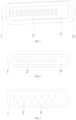
- a circuit protection structure including an insulating plate 1, the insulating plate 1 being provided with a closed protruding rib 11, an enclosing area of the protruding rib 11 being provided with at least one avoiding hole; a patch fuse 2 is provided in the avoiding hole, and the patch fuse 2 is connected to a collecting circuit in series, the patch fuse 2 being electrically connected to the collecting circuit, which achieves the fuse protection of the collecting circuit; both a surface of the insulating plate 1 within the enclosing area of the protruding rib 11 and a surface of the patch fuse 2 are provided with a coated layer 3; and the insulating plate 1 and the patch fuse 2 are provided integrally.
- the patch fuse 2 saves the space occupation of the fuse in the collecting circuit, which saves the cost of the collecting circuit.
- a plurality of patch fuses 2 forms a plastic laminated unit, and the plastic laminated unit may be replaced in its entirety when fused, so as to ensure that the fuses are repairable and replaceable, thereby achieving a circuit protection structure at a relatively low cost.
- the patch fuses 2 within the enclosing area of the protruding rib 11 are provided in the avoiding hole.
- Each patch fuse 2 is mounted in the corresponding collecting circuit by SMT, and the patch fuse 2 and the insulating plate 1 are encapsulated as a single unit by hot pressing.
- a coated layer 3 is coated between the patch fuse 2 and the protruding rib 11 and on a surface of the patch fuse 2 after encapsulating, so as to achieve relative fixation therebetween.
- the coated layer 3 may also protect the patch fuse 2, which prevents the patch fuse 2 from oxidation.
- the coated layer 2 in the present embodiment is a UV adhesive, in which the UV adhesive is used for preventing the fuse from oxidation, thereby preventing the fuse from non-fusing damage.
- Alternative adhesives with equivalent effects may be substituted in other embodiments, which is not specifically limited in the present embodiment.
- each patch fuse 2 within the enclosing area of the protruding rib 11 corresponds to one avoiding hole used for fixing the patch fuse 2 at intervals.
- the patch fuse 2 is mounted in the corresponding collecting circuit by SMT. After the avoiding hole of the insulating plate 1 corresponds to the patch fuse 2, hot pressing and encapsulating are performed to achieve the connection.
- an antioxidant layer is provided between the avoiding hole and the patch fuse 2 to improve the mounting stability, in which the antioxidant layer may include, but is not limited to, such as a UV adhesive, glue and welding.
- the antioxidant layer is provided on the patch fuse 2 to provide protection of antioxidants.
- a circuit assembly including a collecting circuit; an insulating plate 1, the insulating plate 1 being provided with a closed protruding rib 11, an enclosing area of the protruding rib 11 being provided with at least one avoiding hole; a patch fuse 2 is provided in the avoiding hole, and the patch fuse 2 is connected to a collecting circuit in series, the patch fuse 2 being electrically connected to the collecting circuit, which achieves the fuse protection of the collecting circuit; both a surface of the insulating plate 1 within the enclosing area of the protruding rib 11 and a surface of the patch fuse 2 are provided with a coated layer 3; and the insulating plate 1 and the patch fuse 2 are provided integrally.
- the patch fuse 2 saves the space occupation of the fuse in the collecting circuit, which saves the cost of the collecting circuit.
- a plurality of patch fuses 2 form a single unit when laminated with plastic integrally.
- the plastic laminated unit may be replaced in its entirety when fused, so as to ensure that the fuses are repairable and replaceable, thereby achieving a circuit protection structure at a relatively low cost.
- each patch fuse 2 within the enclosing area of the protruding rib 11 corresponds to one avoiding hole used for fixing the patch fuse 2 at intervals.
- the patch fuse 2 is mounted in the corresponding collecting circuit by SMT. After the avoiding hole of the insulating plate 1 corresponds to the patch fuse 2, hot pressing and encapsulating are performed to achieve the connection.
- a sealing layer is provided between the avoiding hole and the patch fuse 2 to improve the mounting stability, in which the sealing layer may include, but is not limited to, such as glue and welding.
- the sealing layer is provided on the patch fuse 2 to provide protection of antioxidants.
- the sealing layer is a UV adhesive, in which the UV adhesive is used for preventing the fuse from oxidation, thereby preventing the fuse from non-fusing damage.
- the patch fuses 2 are arranged in a single line when the enclosing area of the protruding rib 11 is provided with a plurality of avoiding holes, and a plurality of the collecting circuits are connected in parallel; the patch fuses 2 are arranged in a direction that intersects with a direction of parallel connection of a plurality of the collecting circuits so that each collecting circuit corresponds to a patch fuse 2.
- a plurality of patch fuses 2 arranged in a single line may reduce the volume of the insulating plate 1, which also satisfies the condition that the patch fuse 2 corresponds to the collecting circuit one by one.
- the patch fuses 2 are arranged in a staggered arrangement when the enclosing area of the protruding rib 11 is provided with a plurality of avoiding holes, and a plurality of the collecting circuits are connected in parallel; the patch fuses 2 are arranged in a direction that intersects with a direction of parallel connection of a plurality of the collecting circuits so that each collecting circuit corresponds to a patch fuse 2.
- a plurality of patch fuses 2 arranged in a staggered arrangement may provide a relatively large distance between the patch fuses 2, which may increase the distance between the fuses of each row, thereby enabling patch fuse 2 mounting with close spacing between collecting circuits.
- the patch fuses 2 are arranged in a single line and/or a staggered arrangement when the enclosing area of the protruding rib 11 is provided with a plurality of avoiding holes, and the insulating plate 1 may enclose the patch fuses 2 according to the position thereof, only to satisfy that at least one patch fuse 2 is mounted corresponding to each collecting circuit.
- a height of the protruding rib 11 protruding from the insulating plate 1 is greater than that of the patch fuse 2 protruding from the insulating plate 1.
- the protruding rib 11 may provide protection for the fuse, thereby preventing the fuse from external wear and tear.
- Shapes of the insulating plate 1 include but are not limited to, such as oval, circular and rectangular.
- the protruding rib 11 is provided along an exterior edge of the insulating plate 1, which may increase the enclosing area of the protruding rib 11, thereby reducing an overall area of the insulating plate 1.
- the insulating plate 1 is an epoxy resin plate.
- the form of the epoxy resin plate varies, which may be adapted to the requirements placed on the form by various applications: easy curing, curable in the temperature range of 0 ⁇ 180°C; strong adhesion, polar hydroxyl and ether bonds enable high adhesion to a wide range of substances; and low shrinkage, showing very low shrinkage of less than 2% during the curing process.
- the cured epoxy resin system provides excellent mechanical and electrical properties and is an excellent insulating material with high dielectric properties, resistance to surface current leakage, and resistance to electric arcs. which is also chemically stable, dimensionally stable and fungi-resistant.
- the patch fuse 2 is provided integrally in the form of 0603, and 0603 indicates the encapsulating dimensions of an element.
- 0603 is normally indicated in the imperial system, in which 06 indicates a length L of 0.6 inches and 03 indicates a width W of 0.3 inches.
- the collecting circuit is cables of FPC 4 or FFC, so as to achieve protection of the collecting circuit in the FPC 4 or FFC, thereby achieving protection of the collecting circuit in different battery modules.
- the circuit protection structure may not only be applied to the battery module but may also be applied to other devices or components with collecting circuits, so as to achieve the protection of the corresponding collecting circuit, which provides good fusing effect and convenient replacement.
- the provision of protruding rib 11 on the insulating plate 1 is canceled on the basis of embodiment 1 or embodiment 2.
- the insulating plate 1 is provided with at least one avoiding hole; the patch fuse 2 is provided in the avoiding hole, in which the patch fuse 2 is connected to a collecting circuit in series, and both a surface of the insulating plate 1 and a surface of the patch fuse 2 are provided with a coated layer 3, and the insulating plate 1 and the patch fuse 2 are provided integrally, which achieves the protection of the collecting circuit and provides simple assembly and convenient maintenance.
- the present application also relates to a CCS assembly, the CCS assembly including a circuit assembly or a circuit protection structure that may protect the collecting circuit of the CCS assembly at a relatively low cost.
- the present application also relates to an encapsulating method of a circuit assembly, which is applied to a battery module.
- the battery module adopts a prismatic power battery module 1P44S, which includes four cell modules. Each cell module includes 10-13 cells. Firstly, the etched fuse on the FPC 4 of the battery module is canceled.
- the encapsulating method of the circuit assembly is as follows:
- the encapsulating method of the circuit assembly may include steps as follows:
- a patch fuse 2 protection apparatus that is repairable, with stable tolerances and a relatively low overall cost, is designed in the present assembling method.
- the patch fuse When a short circuit occurs in the circuit, the patch fuse is effectively fused. After the troubleshooting, the normal operation of the module may be restored by replacing a new fuse, which reduces the maintenance cost.
- etched circuits require a large width to reduce internal resistance if a certain wire resistance is to be maintained, which increases the cost of the FPC 4.
- the fuses in this application provide stable tolerances and lower overall costs compared to etched fuses.
- circuit protection structure a circuit protection structure, a circuit assembly and an encapsulating method thereof, and a CCS assembly provided in the present application provide technical effects as follows:
Landscapes
- Engineering & Computer Science (AREA)
- Chemical & Material Sciences (AREA)
- Chemical Kinetics & Catalysis (AREA)
- Electrochemistry (AREA)
- General Chemical & Material Sciences (AREA)
- Manufacturing & Machinery (AREA)
- Microelectronics & Electronic Packaging (AREA)
- Fuses (AREA)
Applications Claiming Priority (2)
| Application Number | Priority Date | Filing Date | Title |
|---|---|---|---|
| CN202310333818.4A CN116471743A (zh) | 2023-03-30 | 2023-03-30 | 一种线路保护结构、线路组件及其封装方法、ccs组件 |
| CN202320681089.7U CN219876297U (zh) | 2023-03-30 | 2023-03-30 | 一种线路保护结构、线路组件及ccs组件 |
Publications (1)
| Publication Number | Publication Date |
|---|---|
| EP4439619A1 true EP4439619A1 (de) | 2024-10-02 |
Family
ID=88978313
Family Applications (1)
| Application Number | Title | Priority Date | Filing Date |
|---|---|---|---|
| EP23212535.1A Pending EP4439619A1 (de) | 2023-03-30 | 2023-11-28 | Schaltungsschutzstruktur, schaltungsanordnung und verkapselungsverfahren dafür und ccs-anordnung |
Country Status (2)
| Country | Link |
|---|---|
| EP (1) | EP4439619A1 (de) |
| WO (1) | WO2024198008A1 (de) |
Citations (5)
| Publication number | Priority date | Publication date | Assignee | Title |
|---|---|---|---|---|
| WO2017130306A1 (ja) * | 2016-01-27 | 2017-08-03 | エス・オー・シー株式会社 | チップヒューズ、及びチップヒューズの製造方法 |
| CN108511299A (zh) * | 2018-06-04 | 2018-09-07 | 苏州达晶微电子有限公司 | 一种新型表面贴装熔断器 |
| EP3599800A1 (de) * | 2018-07-23 | 2020-01-29 | Yazaki Corporation | Verbinderanschlussstruktur einer flexiblen leiterplatte |
| US20220190451A1 (en) * | 2019-03-27 | 2022-06-16 | Sanyo Electric Co., Ltd. | Overcurrent protection element and battery system |
| CN217788322U (zh) * | 2021-12-27 | 2022-11-11 | Aem科技(苏州)股份有限公司 | 一种芯片型熔断器 |
Family Cites Families (8)
| Publication number | Priority date | Publication date | Assignee | Title |
|---|---|---|---|---|
| JP4718891B2 (ja) * | 2004-08-02 | 2011-07-06 | 株式会社オートネットワーク技術研究所 | 電気接続箱 |
| CN102629537B (zh) * | 2012-04-10 | 2016-02-17 | 协鑫动力新材料(盐城)有限公司 | 一种保险丝及复合片 |
| JP6507056B2 (ja) * | 2015-07-24 | 2019-04-24 | 株式会社オートネットワーク技術研究所 | 電池配線モジュール |
| US11081308B2 (en) * | 2019-08-06 | 2021-08-03 | Littelfuse, Inc. | Vertical surface mount device pass-through fuse |
| CN212230385U (zh) * | 2020-07-09 | 2020-12-25 | 唐山航宇电力电子设备有限公司 | 应用于开关电源的贴片式熔断器 |
| JP7567389B2 (ja) * | 2020-11-17 | 2024-10-16 | 株式会社オートネットワーク技術研究所 | 配線モジュール |
| CN217086672U (zh) * | 2022-02-10 | 2022-07-29 | 瑞浦兰钧能源股份有限公司 | 一种二次电池模组采样结构 |
| CN217214998U (zh) * | 2022-03-29 | 2022-08-16 | 广州小鹏汽车科技有限公司 | 一种电池包和车辆 |
-
2023
- 2023-04-20 WO PCT/CN2023/089436 patent/WO2024198008A1/zh not_active Ceased
- 2023-11-28 EP EP23212535.1A patent/EP4439619A1/de active Pending
Patent Citations (5)
| Publication number | Priority date | Publication date | Assignee | Title |
|---|---|---|---|---|
| WO2017130306A1 (ja) * | 2016-01-27 | 2017-08-03 | エス・オー・シー株式会社 | チップヒューズ、及びチップヒューズの製造方法 |
| CN108511299A (zh) * | 2018-06-04 | 2018-09-07 | 苏州达晶微电子有限公司 | 一种新型表面贴装熔断器 |
| EP3599800A1 (de) * | 2018-07-23 | 2020-01-29 | Yazaki Corporation | Verbinderanschlussstruktur einer flexiblen leiterplatte |
| US20220190451A1 (en) * | 2019-03-27 | 2022-06-16 | Sanyo Electric Co., Ltd. | Overcurrent protection element and battery system |
| CN217788322U (zh) * | 2021-12-27 | 2022-11-11 | Aem科技(苏州)股份有限公司 | 一种芯片型熔断器 |
Also Published As
| Publication number | Publication date |
|---|---|
| WO2024198008A1 (zh) | 2024-10-03 |
Similar Documents
| Publication | Publication Date | Title |
|---|---|---|
| KR102595362B1 (ko) | 배터리 팩 및 차량 | |
| EP2385568B1 (de) | Schutzschaltungsmodul und wiederaufladbare Batterie damit | |
| JP7474745B2 (ja) | 過電流保護素子とバッテリーシステム | |
| US11302990B2 (en) | Battery module | |
| WO2014023480A1 (de) | Gehäuse für eine batteriezelle mit einem gehäusedeckel eine überwachungselektronik aufweisend, batteriezelle, batteriemodul sowie kraftfahrzeug | |
| CN106299223B (zh) | 电池模组 | |
| CN109950448B (zh) | 软包锂电池模组 | |
| CN204651430U (zh) | 电池模组电压采集组件及具有该电压采集组件的电池模组 | |
| US20200373542A1 (en) | Battery power extraction and integration structure, battery pack and vehicle | |
| JP7589925B2 (ja) | ヒューズラインを備えるフィルム型ケーブル | |
| US12144107B2 (en) | Substrate connection structure and vehicle wiring module | |
| CN220138626U (zh) | 一种集成母排及电池包 | |
| EP4439619A1 (de) | Schaltungsschutzstruktur, schaltungsanordnung und verkapselungsverfahren dafür und ccs-anordnung | |
| CN219876297U (zh) | 一种线路保护结构、线路组件及ccs组件 | |
| WO2014023725A1 (de) | Gehäuse für eine batteriezelle mit einem gehäusedeckel eine überwachungselektronik aufweisend, batteriezelle, batteriemodul sowie kraftfahrzeug | |
| CN116073079A (zh) | 一种车载电池模组电连接组件及电池模组 | |
| DE202012012655U1 (de) | Gehäuse für eine Batteriezelle mit einem Gehäusedeckel eine Überwachungselektronik aufweisend, Batteriezelle, Batteriemodul sowie Kraftfahrzeug | |
| CN116471743A (zh) | 一种线路保护结构、线路组件及其封装方法、ccs组件 | |
| CN221126206U (zh) | 集成采集母排及电池包 | |
| CN222775549U (zh) | 采集组件及电池包 | |
| CN221126193U (zh) | 电池及具有其的终端设备 | |
| CN223828461U (zh) | 一种电池结构及电池组 | |
| CN219591603U (zh) | 一种线束隔离板组件和电池包 | |
| CN219067154U (zh) | 输出极铝排、电池信号采集装置及电池模组 | |
| CN224110424U (zh) | 电池包及车辆 |
Legal Events
| Date | Code | Title | Description |
|---|---|---|---|
| PUAI | Public reference made under article 153(3) epc to a published international application that has entered the european phase |
Free format text: ORIGINAL CODE: 0009012 |
|
| STAA | Information on the status of an ep patent application or granted ep patent |
Free format text: STATUS: EXAMINATION IS IN PROGRESS |
|
| 17P | Request for examination filed |
Effective date: 20231128 |
|
| AK | Designated contracting states |
Kind code of ref document: A1 Designated state(s): AL AT BE BG CH CY CZ DE DK EE ES FI FR GB GR HR HU IE IS IT LI LT LU LV MC ME MK MT NL NO PL PT RO RS SE SI SK SM TR |