EP4439033A1 - Metal vapour pressure detection apparatus and detection method - Google Patents
Metal vapour pressure detection apparatus and detection method Download PDFInfo
- Publication number
- EP4439033A1 EP4439033A1 EP23740113.8A EP23740113A EP4439033A1 EP 4439033 A1 EP4439033 A1 EP 4439033A1 EP 23740113 A EP23740113 A EP 23740113A EP 4439033 A1 EP4439033 A1 EP 4439033A1
- Authority
- EP
- European Patent Office
- Prior art keywords
- displacement
- pressure
- metal
- slider
- metal vapour
- Prior art date
- Legal status (The legal status is an assumption and is not a legal conclusion. Google has not performed a legal analysis and makes no representation as to the accuracy of the status listed.)
- Granted
Links
Images

Classifications
-
- G—PHYSICS
- G01—MEASURING; TESTING
- G01L—MEASURING FORCE, STRESS, TORQUE, WORK, MECHANICAL POWER, MECHANICAL EFFICIENCY, OR FLUID PRESSURE
- G01L19/00—Details of, or accessories for, apparatus for measuring steady or quasi-steady pressure of a fluent medium insofar as such details or accessories are not special to particular types of pressure gauges
- G01L19/0007—Fluidic connecting means
-
- G—PHYSICS
- G01—MEASURING; TESTING
- G01L—MEASURING FORCE, STRESS, TORQUE, WORK, MECHANICAL POWER, MECHANICAL EFFICIENCY, OR FLUID PRESSURE
- G01L11/00—Measuring steady or quasi-steady pressure of a fluid or a fluent solid material by means not provided for in group G01L7/00 or G01L9/00
- G01L11/004—Measuring steady or quasi-steady pressure of a fluid or a fluent solid material by means not provided for in group G01L7/00 or G01L9/00 by the use of counterbalancing forces
-
- C—CHEMISTRY; METALLURGY
- C23—COATING METALLIC MATERIAL; COATING MATERIAL WITH METALLIC MATERIAL; CHEMICAL SURFACE TREATMENT; DIFFUSION TREATMENT OF METALLIC MATERIAL; COATING BY VACUUM EVAPORATION, BY SPUTTERING, BY ION IMPLANTATION OR BY CHEMICAL VAPOUR DEPOSITION, IN GENERAL; INHIBITING CORROSION OF METALLIC MATERIAL OR INCRUSTATION IN GENERAL
- C23C—COATING METALLIC MATERIAL; COATING MATERIAL WITH METALLIC MATERIAL; SURFACE TREATMENT OF METALLIC MATERIAL BY DIFFUSION INTO THE SURFACE, BY CHEMICAL CONVERSION OR SUBSTITUTION; COATING BY VACUUM EVAPORATION, BY SPUTTERING, BY ION IMPLANTATION OR BY CHEMICAL VAPOUR DEPOSITION, IN GENERAL
- C23C14/00—Coating by vacuum evaporation, by sputtering or by ion implantation of the coating forming material
- C23C14/06—Coating by vacuum evaporation, by sputtering or by ion implantation of the coating forming material characterised by the coating material
- C23C14/14—Metallic material, boron or silicon
-
- C—CHEMISTRY; METALLURGY
- C23—COATING METALLIC MATERIAL; COATING MATERIAL WITH METALLIC MATERIAL; CHEMICAL SURFACE TREATMENT; DIFFUSION TREATMENT OF METALLIC MATERIAL; COATING BY VACUUM EVAPORATION, BY SPUTTERING, BY ION IMPLANTATION OR BY CHEMICAL VAPOUR DEPOSITION, IN GENERAL; INHIBITING CORROSION OF METALLIC MATERIAL OR INCRUSTATION IN GENERAL
- C23C—COATING METALLIC MATERIAL; COATING MATERIAL WITH METALLIC MATERIAL; SURFACE TREATMENT OF METALLIC MATERIAL BY DIFFUSION INTO THE SURFACE, BY CHEMICAL CONVERSION OR SUBSTITUTION; COATING BY VACUUM EVAPORATION, BY SPUTTERING, BY ION IMPLANTATION OR BY CHEMICAL VAPOUR DEPOSITION, IN GENERAL
- C23C14/00—Coating by vacuum evaporation, by sputtering or by ion implantation of the coating forming material
- C23C14/22—Coating by vacuum evaporation, by sputtering or by ion implantation of the coating forming material characterised by the process of coating
- C23C14/54—Controlling or regulating the coating process
- C23C14/542—Controlling the film thickness or evaporation rate
- C23C14/543—Controlling the film thickness or evaporation rate using measurement on the vapor source
-
- G—PHYSICS
- G01—MEASURING; TESTING
- G01L—MEASURING FORCE, STRESS, TORQUE, WORK, MECHANICAL POWER, MECHANICAL EFFICIENCY, OR FLUID PRESSURE
- G01L19/00—Details of, or accessories for, apparatus for measuring steady or quasi-steady pressure of a fluent medium insofar as such details or accessories are not special to particular types of pressure gauges
- G01L19/14—Housings
- G01L19/147—Details about the mounting of the sensor to support or covering means
-
- G—PHYSICS
- G01—MEASURING; TESTING
- G01L—MEASURING FORCE, STRESS, TORQUE, WORK, MECHANICAL POWER, MECHANICAL EFFICIENCY, OR FLUID PRESSURE
- G01L27/00—Testing or calibrating of apparatus for measuring fluid pressure
-
- G—PHYSICS
- G01—MEASURING; TESTING
- G01L—MEASURING FORCE, STRESS, TORQUE, WORK, MECHANICAL POWER, MECHANICAL EFFICIENCY, OR FLUID PRESSURE
- G01L27/00—Testing or calibrating of apparatus for measuring fluid pressure
- G01L27/002—Calibrating, i.e. establishing true relation between transducer output value and value to be measured, zeroing, linearising or span error determination
-
- G—PHYSICS
- G01—MEASURING; TESTING
- G01L—MEASURING FORCE, STRESS, TORQUE, WORK, MECHANICAL POWER, MECHANICAL EFFICIENCY, OR FLUID PRESSURE
- G01L9/00—Measuring steady of quasi-steady pressure of fluid or fluent solid material by electric or magnetic pressure-sensitive elements; Transmitting or indicating the displacement of mechanical pressure-sensitive elements, used to measure the steady or quasi-steady pressure of a fluid or fluent solid material, by electric or magnetic means
- G01L9/0001—Transmitting or indicating the displacement of elastically deformable gauges by electric, electro-mechanical, magnetic or electro-magnetic means
-
- G—PHYSICS
- G01—MEASURING; TESTING
- G01L—MEASURING FORCE, STRESS, TORQUE, WORK, MECHANICAL POWER, MECHANICAL EFFICIENCY, OR FLUID PRESSURE
- G01L9/00—Measuring steady of quasi-steady pressure of fluid or fluent solid material by electric or magnetic pressure-sensitive elements; Transmitting or indicating the displacement of mechanical pressure-sensitive elements, used to measure the steady or quasi-steady pressure of a fluid or fluent solid material, by electric or magnetic means
- G01L9/0089—Transmitting or indicating the displacement of pistons by electrical, electromechanical, magnetic or electromagnetic means
-
- C—CHEMISTRY; METALLURGY
- C23—COATING METALLIC MATERIAL; COATING MATERIAL WITH METALLIC MATERIAL; CHEMICAL SURFACE TREATMENT; DIFFUSION TREATMENT OF METALLIC MATERIAL; COATING BY VACUUM EVAPORATION, BY SPUTTERING, BY ION IMPLANTATION OR BY CHEMICAL VAPOUR DEPOSITION, IN GENERAL; INHIBITING CORROSION OF METALLIC MATERIAL OR INCRUSTATION IN GENERAL
- C23C—COATING METALLIC MATERIAL; COATING MATERIAL WITH METALLIC MATERIAL; SURFACE TREATMENT OF METALLIC MATERIAL BY DIFFUSION INTO THE SURFACE, BY CHEMICAL CONVERSION OR SUBSTITUTION; COATING BY VACUUM EVAPORATION, BY SPUTTERING, BY ION IMPLANTATION OR BY CHEMICAL VAPOUR DEPOSITION, IN GENERAL
- C23C14/00—Coating by vacuum evaporation, by sputtering or by ion implantation of the coating forming material
- C23C14/22—Coating by vacuum evaporation, by sputtering or by ion implantation of the coating forming material characterised by the process of coating
- C23C14/24—Vacuum evaporation
-
- Y—GENERAL TAGGING OF NEW TECHNOLOGICAL DEVELOPMENTS; GENERAL TAGGING OF CROSS-SECTIONAL TECHNOLOGIES SPANNING OVER SEVERAL SECTIONS OF THE IPC; TECHNICAL SUBJECTS COVERED BY FORMER USPC CROSS-REFERENCE ART COLLECTIONS [XRACs] AND DIGESTS
- Y02—TECHNOLOGIES OR APPLICATIONS FOR MITIGATION OR ADAPTATION AGAINST CLIMATE CHANGE
- Y02E—REDUCTION OF GREENHOUSE GAS [GHG] EMISSIONS, RELATED TO ENERGY GENERATION, TRANSMISSION OR DISTRIBUTION
- Y02E30/00—Energy generation of nuclear origin
- Y02E30/30—Nuclear fission reactors
Definitions
- the present invention belongs to the technical field of metal vapour detection, and particularly relates to a metal vapour pressure detection apparatus and detection method.
- PVD Physical vapor deposition
- a variety of coating materials such as zinc, aluminum, magnesium, and chromium can be used.
- the coating speed is generally fast, typically up to 1-3 m/s.
- it is required to maintain a relatively constant metal vapour flow rate and pressure of metal vapour during the spraying process.
- the pressure of metal vapour is critical for controlling the spraying process and is one of the key parameters that determine the bonding strength between the coating and the substrate.
- the present invention provides a metal vapour pressure detection apparatus and detection method.
- a displacement generation system and a displacement detection system By setting up a displacement generation system and a displacement detection system on an outer side of a metal evaporation cavity, and the pressure of metal vapour is directly measured according to a displacement of a displacement slider detected in real time and a relationship curve between a pressure and the displacement obtained by gas calibration, providing a basis for online control and adjustment of metal vapour.
- the present invention adopts the following technical solutions:
- the displacement detection system includes a fixed bracket and a displacement sensor; the fixed bracket is provided with a spring limiting block connected to the pressure balance spring, a fixing ring sleeved on the displacement slider sleeve, and a sensor fixing block for mounting the displacement sensor; and the spring limiting block is disposed between the fixing ring and the sensor fixing block, and the spring limiting block is provided with a light-transmitting hole corresponding to the displacement sensor.
- the displacement generation system further includes a heater disposed in the displacement slider sleeve.
- the pressure balance spring is composed of 1-10 springs, with a wire diameter of 0.1-6 mm.
- a center of the displacement sensor, a center of the light-transmitting hole, and a center of the pressure balance spring are on the same axis.
- the pressure detection mechanism further includes an intelligent processing module; and the intelligent processing module is used to receive the coordinates of the displacement slider detected by the displacement sensor, calculate a displacement of the displacement slider, and obtain the pressure of the metal vapour according to the displacement of the displacement slider and a relationship curve between the displacement and a pressure obtained by calibration.
- the intelligent processing module is used to receive the coordinates of the displacement slider detected by the displacement sensor, calculate a displacement of the displacement slider, and obtain the pressure of the metal vapour according to the displacement of the displacement slider and a relationship curve between the displacement and a pressure obtained by calibration.
- the second aspect of the present invention provides a metal vapour pressure detection method, using the metal vapour pressure detection apparatus described above.
- the detection method includes the steps of:
- the gas has a pressure of 1 ⁇ 10 3 -1 ⁇ 10 5 Pa.
- the displacement slider sleeve is heated by a heater to a temperature of 20-1000°C during movement of the displacement slider.
- 1-metal evaporation cavity 2-metal evaporation area, 3-pressure detection mechanism, 4-displacement slider, 5-displacement slider sleeve, 6-pressure balance spring, 7-fixed bracket (7-1 spring limiting block; 7-2 sensor fixing block; 7-3 fixing ring), 8-displacement sensor, and 9-heater.
- the present invention provides a metal vapour pressure detection apparatus, including a metal evaporation cavity 1 and a pressure detection mechanism 3 disposed on an outer side of the metal evaporation cavity 1.
- the metal evaporation cavity 1 is used to melt and evaporate metal to form metal vapour, with its interior being a metal evaporation area 2.
- the pressure detection mechanism 3 includes a displacement generation system and a displacement detection system disposed on the displacement generation system.
- the displacement generation system includes a displacement slider sleeve 5 (as shown in Figures 5a and 5b ), a displacement slider 4 disposed in the displacement slider sleeve 5, and a pressure balance spring 6 connected to the displacement slider 4.
- the displacement slider sleeve 5 is in communication with the metal evaporation cavity 1, and the displacement slider 4 slides radially along the displacement slider sleeve 5 under a pressure of the metal vapour.
- One end (movable end) of the pressure balance spring 6 is connected to the displacement slider 4, and the other end (fixed end) of the pressure balance spring 6 is connected to the displacement detection system.
- the pressure detection mechanism 3 calculates a displacement of the displacement slider 4 based on the coordinates of the displacement slider 4 detected by the displacement detection system, and thereby determines the pressure of metal vapour.
- the displacement detection system of the present invention further includes a fixed bracket 7 and a displacement sensor 8.
- the fixed bracket 7 is provided with a spring limiting block 7-1 connected to the pressure balance spring 6, a fixing ring 7-3 sleeved on the displacement slider sleeve 5, and a sensor fixing block 7-2 for mounting the displacement sensor 8.
- Two fixing rings 7-3 are arranged in order to make the fixed bracket more stable.
- the spring limiting block 7-1 is disposed between the fixing ring 7-3 and the sensor fixing block 7-2, and is provided with a light-transmitting hole corresponding to the displacement sensor 8.
- the fixed bracket 7 serves three functions: firstly, the position of the fixed end is defined by the spring limiting block 7-1 when the pressure balance spring 6 is deformed, and the light-transmitting hole corresponding to the displacement sensor 8 is designed in the spring limiting block 7-1, facilitating the displacement sensor 8 to perform real-time measurement on the coordinates of the displacement slider 4; secondly, the displacement sensor 8 is mounted on the sensor fixing block 7-2, which can measure the displacement of the displacement slider 4 under the action of metal vapour; and thirdly, the fixed bracket 7 is mounted on the displacement slider sleeve 5 through the fixing rings 7-3, making the fixed bracket 7 an important component connecting the displacement generation system and the displacement detection system.
- a center of the displacement sensor 8, a center of the pressure balance spring 6, and a center of the light-transmitting hole are essentially on the same axis to ensure that the displacement sensor 8 is not obstructed by other components during the measurement.
- the displacement generation system further includes a heater 9 disposed within the displacement slider sleeve 5, which can heat the displacement slider sleeve 5 to a temperature above the metal vapour temperature.
- the heater 9 employs resistance heating or induction heating, with a heating temperature range of 20-1000°C.
- a reasonable pressure balance spring 6 may be designed according to different pressure ranges.
- the pressure balance spring 6 may be composed of a single spring or multiple springs, thereby enabling a wide range of metal vapour pressure measurements.
- the pressure balance spring 6 is composed of 1-10 springs.
- the multiple springs are connected in series to form the pressure balance spring 6.
- three springs with different wire diameters (6-1, 6-2, and 6-3) are connected in series to form the pressure balance spring 6.
- a wire diameter of each spring can be designed according to a pressure range to be measured, with a selectable wire diameter between 0.1 mm and 6 mm.
- the pressure detection mechanism 3 further includes an intelligent processing module.
- the intelligent processing module receives the coordinates of the displacement slider 4 measured in real time by the displacement sensor 8, calculates a displacement ⁇ S of the displacement slider 4, and obtains the pressure of the metal vapour according to the displacement ⁇ S and a relationship curve between a pressure and the displacement ⁇ S of the displacement slider 4 obtained by calibration, thereby obtaining the pressure of the metal vapour in real time.
- the metal vapour pressure detection apparatus of the present invention can be used for measuring metal vapour pressure under both normal and vacuum conditions, making it suitable for measuring metal vapour pressure under various operating conditions.
- the metal vapour pressure detection apparatus of the present invention can directly obtain the pressure of the metal vapour, with minimal influence from other factors, and has a high anti-interference ability, and relatively stable pressure measurement.
- the displacement slider 4 When the metal vapour pressure detection apparatus of the present invention is in use, in the absence of metal vapour, the displacement slider 4 rests against the metal evaporation cavity 1 (an outer wall of the metal evaporation cavity 1 is provided with a limiting part to keep the displacement slider 4 within the displacement slider sleeve 5) under the compressive stress of the pressure balance spring 6, forming a force equilibrium.
- This position represents coordinates of the displacement slider 4 when it has not moved, referred to as a zero position S 0 .
- Figures 3a and 3b when metal vapour is generated (or other gases are introduced) in the metal evaporation cavity 1, as the evaporation process proceeds, the metal vapour pressure in the metal evaporation cavity 1 increases.
- the displacement slider 4 When the metal vapour pressure exceeds the initial compressive stress of the pressure balance spring 6, the net external force on the displacement slider 4 is directed away from the metal evaporation cavity 1 (outward).
- the displacement slider 4 moves along a wall of the displacement slider sleeve 5 in a direction away from the metal evaporation cavity 1.
- the pressure balance spring 6 gradually contracts under extrusion of the displacement slider 4, and at the same time, its compressive stress to the displacement slider 4 gradually increases.
- the compressive stress of the pressure balance spring 6 equals the pressure of the metal vapour, the displacement slider 4 reaches a force equilibrium and stops moving.
- the pressure of the metal vapour generated inside the metal evaporation cavity 1 decreases, when the pressure of the metal vapour is less than the compressive stress of the pressure balance spring 6, the net external force of the displacement slider 4 is directed towards the metal evaporation cavity 1 (inward).
- the displacement slider 4 moves towards the metal evaporation cavity 1, and the compressive stress of the pressure balance spring 6 on the displacement slider 4 gradually decreases.
- the compressive stress of the pressure balance spring 6 on the displacement slider 4 equals the metal vapour pressure, the displacement slider 4 stops moving.
- the displacement slider 4 moves toward the metal evaporation cavity 1 under the internal stress of the pressure balance spring 6 until it rests against the metal evaporation cavity 1, indicating that the metal vapour pressure is lower than the minimum detection pressure of the metal vapour pressure detection apparatus.
- the coordinates of the displacement slider 4 are measured in real time by the displacement sensor 8 and transferred to the intelligent processing module, which can calculate the displacement ⁇ S of the displacement slider 4 in real time, and then determine the pressure of the metal vapour according to the displacement ⁇ S and the relationship curve between the pressure and the displacement obtained through gas calibration.
- the pressure of the metal vapour is detected by using the metal vapour pressure detection apparatus described above, wherein a detection method includes the following steps: S 1, introduce gas with different pressures into a metal evaporation cavity of the metal vapour pressure detection apparatus for repeated calibration to obtain a relationship curve between a pressure and a displacement of a displacement slider.
- the specific process is as follows: before a metal vapour pressure is obtained, a relationship between a pressure of the metal vapour pressure detection apparatus and the displacement of the displacement slider is first calibrated. Gas with a known pressure is introduced into the metal evaporation cavity, the displacement slider moves away from the metal evaporation cavity under the action of the gas, a pressure balance spring gradually contracts under extrusion of the displacement slider while exerting an inward compressive stress to the displacement slider until the displacement slider reaches a force equilibrium and stops moving.
- the displacement detection system measures coordinates of the displacement slider in real time.
- the displacement slider When no gas is introduced into the metal evaporation cavity, the displacement slider rests against the limiting part on the outer wall of the metal evaporation cavity under the action of the inward compressive stress of the pressure balance spring, forming a force equilibrium, and at this time, the position of the displacement slider is recorded as the zero position S 0 . Based on the above process, obtain the relationship curve between the pressure and the displacement of the displacement slider. In order to ensure the accuracy of data, repeated calibrations are required. Additionally, the pressure of the gas also needs to be increased or decreased to perform multiple repeated calibrations of the relationship between the pressure and the displacement of the displacement slider for a plurality of times to obtain the relationship curve between the pressure and the displacement of the displacement slider.
- the gas used during calibration has a pressure of 1 ⁇ 10 3 -1 ⁇ 10 5 Pa.
- the displacement slider slides along a displacement slider sleeve under a pressure of the metal vapour.
- the pressure balance spring gradually contracts under extrusion of the displacement slider until the displacement slider reaches a force equilibrium and stops moving.
- the displacement detection system detects coordinates of the displacement slider in real time to obtain a displacement of the displacement slider.
- the specific process is as follows: melt and evaporate the metal to form the metal vapour in the metal evaporation cavity.
- the pressure of the metal vapour exceeds an initial internal stress of the pressure balance spring
- the displacement slider slides along the displacement slider sleeve under the pressure of the metal vapour.
- the pressure balance spring gradually contracts under the extrusion of the displacement slider.
- the displacement slider stops moving.
- the displacement at this time can be recalculated based on the coordinates detected by the displacement detection system after the displacement slider reaches a force equilibrium again.
- the displacement slider sleeve is heated by a heater to a temperature of 20-1000°C.
- the specific process is as follows: the pressure of the metal vapour is obtained in real time according to the relationship curve between the pressure and the displacement of the displacement slider obtained in the step S 1 and the displacement detected in the step S2.
- the metal vapour pressure detection apparatus and detection method of the present invention are further described below with reference to specific examples.
- the metal vapour pressure to be measured is in the range of 5 ⁇ 10 3 -1 ⁇ 10 5 Pa
- the pressure balance spring 4 is composed of a single spring with a wire diameter of 4-6 mm.
- the implementation steps are as follows: First, the metal vapour pressure detection apparatus is calibrated as follows: In an initial state, the displacement sensor 8 records coordinates S 0 of an initial zero position of the displacement slider 4 and sends them to the intelligent processing module.
- the displacement slider 4 moves outward under the net external force.
- the pressure of the nitrogen gas in the cavity can be measured by a pressure gauge, and the displacement sensor 8 can detect the displacement of the displacement slider 4 in real time to obtain a relationship between the displacement and the pressure during the increase of the gas pressure.
- the displacement of the displacement slider 4 and a corresponding value of the gas pressure in the metal evaporation cavity are sent to the intelligent processing module in real time. By repeating the measurement for a plurality of times, a relationship curve between the displacement and the pressure is obtained.
- the metal vapour pressure in the metal evaporation cavity is obtained by using the relationship curve between the displacement and the pressure from the above calibration.
- the intelligent processing module sends the real-time temperature inside the metal evaporation cavity 1 to the heater 9, which heats the displacement slider sleeve 5 to a target temperature (greater than or equal to the metal vapour temperature) to avoid condensation of the metal vapour on the pressure detection apparatus.
- the displacement sensor 8 detects the displacement generated by the displacement slider 4 in real time.
- the real time pressure of the metal vapour in the metal evaporation cavity 1 is determined using the relationship curve between the displacement and pressure obtained from the calibration.
- the metal vapour pressure to be measured is in the range of 1 ⁇ 10 3 -5 ⁇ 10 3 Pa
- the pressure balance spring 4 is composed of a single spring with a wire diameter of 2-5 mm.
- the specific implementation method and steps are the same as those in Example 1.
- the metal vapour pressure to be measured is in the range of 1 ⁇ 10 3 -5 ⁇ 10 3 Pa
- the pressure balance spring 4 is composed of two or more springs with different wire diameters in series, with wire diameters of 0.1-5 mm. This allows for high-precision metal vapour pressure detection.
- the displacement generation system and the displacement detection system are disposed on the outer side of the metal evaporation cavity, and the pressure of metal vapour is directly obtained according to the displacement of the displacement slider detected in real time and the relationship curve between the pressure and the displacement obtained by gas calibration, providing a basis for online control and adjustment of metal vapour.
- the metal vapour pressure detection apparatus and detection method of the present invention can monitor the metal vapour pressure in a temperature range from normal temperature to 1000°C in real time, providing a stable detection and adjustment basis for metal evaporation control.
- the metal vapour pressure detection apparatus and detection method of the present invention are suitable for detecting pressures of various metal vapours, with good structural flexibility and process compatibility.
- the metal vapour pressure detection apparatus of the present invention is simple in structure, suitable for various operating conditions and environments, and particularly suitable for metal vapour pressure detection under vacuum conditions. It is cost-effective, easy to operate and maintain, and facilitates automatic interlocking control.
Landscapes
- Physics & Mathematics (AREA)
- General Physics & Mathematics (AREA)
- Chemical & Material Sciences (AREA)
- Chemical Kinetics & Catalysis (AREA)
- Engineering & Computer Science (AREA)
- Materials Engineering (AREA)
- Mechanical Engineering (AREA)
- Metallurgy (AREA)
- Organic Chemistry (AREA)
- Analytical Chemistry (AREA)
- Electromagnetism (AREA)
- Measuring Fluid Pressure (AREA)
Abstract
Description
- The present invention belongs to the technical field of metal vapour detection, and particularly relates to a metal vapour pressure detection apparatus and detection method.
- Physical vapor deposition (PVD) is a widely used material surface treatment technology that evaporates metals, alloys, or compounds in a vacuum environment, causing the formed metal vapour to condense and deposit on a substrate. Coating the surface of a material by using this technology enables a coating to have better wear resistance, corrosion resistance, and dry lubrication, as well as high hardness, which can significantly improve the performance and service life of the material. This technology is environmentally friendly and widely used in the fields of machinery, electronics, hardware, aerospace, chemical industry, etc., making it an important application technology in green manufacturing.
- In the application of the physical vapor deposition technology, a variety of coating materials, such as zinc, aluminum, magnesium, and chromium can be used. The coating speed is generally fast, typically up to 1-3 m/s. In order to obtain a better coating surface quality and spraying effect, it is required to maintain a relatively constant metal vapour flow rate and pressure of metal vapour during the spraying process. The pressure of metal vapour is critical for controlling the spraying process and is one of the key parameters that determine the bonding strength between the coating and the substrate.
- At present, common pressure detection devices are mainly suitable for gases and water vapour. Since metal vapor is a high-temperature airflow, it easily condenses in low temperature regions, and some metals are relatively reactive and can easily react with other metals to corrode them. Therefore, existing pressure detection devices cannot directly obtain the pressure of metal vapour. At present, there are few reports on metal vapour pressure detection methods, and most of them use indirect methods for pressure measurement.
- After literature research and patent searches, there is currently no method or apparatus for directly measuring metal vapour pressure. Therefore, it is necessary to develop a measurement method and apparatus that can directly obtain the metal vapour pressure to provide a basis for online control and adjustment of metal vapour.
- To address the above deficiencies existing in the prior art, the present invention provides a metal vapour pressure detection apparatus and detection method. By setting up a displacement generation system and a displacement detection system on an outer side of a metal evaporation cavity, and the pressure of metal vapour is directly measured according to a displacement of a displacement slider detected in real time and a relationship curve between a pressure and the displacement obtained by gas calibration, providing a basis for online control and adjustment of metal vapour.
- To achieve the above object, the present invention adopts the following technical solutions:
- The first aspect of the present invention provides a metal vapour pressure detection apparatus, including a metal evaporation cavity and a pressure detection mechanism disposed on an outer side of the metal evaporation cavity, wherein
- the metal evaporation cavity is used to melt and evaporate metal to form metal vapour; and
- the pressure detection mechanism includes a displacement generation system and a displacement detection system disposed on the displacement generation system; the displacement generation system includes a displacement slider sleeve, a displacement slider disposed in the displacement slider sleeve, and a pressure balance spring connected to the displacement slider, the displacement slider sleeve is in communication with the metal evaporation cavity, and the displacement slider slides along the displacement slider sleeve under a pressure of the metal vapour; one end of the pressure balance spring is connected to the displacement slider, and the other end is connected to the displacement detection system; and the pressure detection mechanism determines the pressure of the metal vapour according to coordinates of the displacement slider detected by the displacement detection system.
- Preferably, the displacement detection system includes a fixed bracket and a displacement sensor; the fixed bracket is provided with a spring limiting block connected to the pressure balance spring, a fixing ring sleeved on the displacement slider sleeve, and a sensor fixing block for mounting the displacement sensor; and the spring limiting block is disposed between the fixing ring and the sensor fixing block, and the spring limiting block is provided with a light-transmitting hole corresponding to the displacement sensor.
- Preferably, the displacement generation system further includes a heater disposed in the displacement slider sleeve.
- Preferably, the pressure balance spring is composed of 1-10 springs, with a wire diameter of 0.1-6 mm.
- Preferably, a center of the displacement sensor, a center of the light-transmitting hole, and a center of the pressure balance spring are on the same axis.
- Preferably, the pressure detection mechanism further includes an intelligent processing module; and the intelligent processing module is used to receive the coordinates of the displacement slider detected by the displacement sensor, calculate a displacement of the displacement slider, and obtain the pressure of the metal vapour according to the displacement of the displacement slider and a relationship curve between the displacement and a pressure obtained by calibration.
- The second aspect of the present invention provides a metal vapour pressure detection method, using the metal vapour pressure detection apparatus described above. The detection method includes the steps of:
-
S 1, introducing gas with different pressures into a metal evaporation cavity of the metal vapour pressure detection apparatus for repeated calibration to obtain a relationship curve between a pressure and a displacement of a displacement slider; - S2, melting and evaporating metal to form metal vapour in the metal evaporation cavity, wherein the displacement slider slides along a displacement slider sleeve under a pressure of the metal vapour, and a pressure balance spring gradually contracts under extrusion of the displacement slider until the displacement slider reaches a force equilibrium and stops moving, and a displacement detection system detects coordinates of the displacement slider in real time to obtain a displacement of the displacement slider; and
- S3, obtaining the pressure of the metal vapour according to the relationship curve between the pressure and the displacement of the displacement slider obtained in the step S1 and the displacement of the displacement slider obtained in the step S2.
- Preferably, in the step S1, the gas has a pressure of 1×10³-1×10⁵ Pa.
- Preferably, in the step S2, the displacement ΔS of the displacement slider is:

- wherein ΔS is the displacement of the displacement slider, in mm;
- St represents coordinates of the displacement slider when it reaches a force equilibrium after moving, in mm; and
- S0 represents coordinates of the displacement slider at a zero position (the initial coordinate of the displacement slider), in mm.
- Preferably, in the step S2, the displacement slider sleeve is heated by a heater to a temperature of 20-1000°C during movement of the displacement slider.
- The metal vapour pressure detection apparatus and detection method provided by the present invention have the following beneficial effects:
- 1. The metal vapour pressure detection apparatus and detection method of the present invention, through the displacement generation system and the displacement detection system disposed on the outer side of the metal evaporation cavity, directly measure the pressure of the metal vapour based on the displacement of the displacement slider detected in real time and the relationship curve between the pressure and the displacement obtained by gas calibration, thereby providing a basis for online control and adjustment of metal vapour.
- 2. The metal vapour pressure detection apparatus and detection method of the present invention can monitor the metal vapour pressure in a temperature range from normal temperature to 1000°C in real time, providing a stable detection and adjustment basis for metal evaporation control.
- 3. The metal vapour pressure detection apparatus and detection method of the present invention are suitable for directly obtaining pressures of various metal vapours, featuring good structural adaptability and process compatibility.
- 4. The metal vapour pressure detection apparatus of the present invention is simple in structure, suitable for various operating conditions and environments, cost-effective, easy to operate and maintain, and facilitates automatic interlocking control.
-
-
Figure 1 is a structural schematic diagram of a metal vapour pressure detection apparatus according to the present invention. -
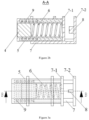
Figure 2a is a structural schematic diagram of a pressure detection mechanism according to the present invention. -
Figure 2b is a sectional view taken along line A-A ofFigure 2a . -
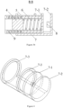
Figure 3a is a schematic diagram showing a displacement slider of the pressure detection mechanism of the present invention under the action of metal vapour pressure. -
Figure 3b is a sectional view taken along line B-B ofFigure 3a . -
Figure 4 is a structural schematic diagram of a fixed bracket according to the present invention. -
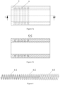
Figure 5a is a structural schematic diagram of a displacement slider sleeve according to the present invention. -
Figure 5b is a sectional view taken along line C-C ofFigure 5a . -
Figure 6 is a structural schematic diagram of a pressure balance spring composed of multiple springs having different specifications, such as wire diameters. - 1-metal evaporation cavity, 2-metal evaporation area, 3-pressure detection mechanism, 4-displacement slider, 5-displacement slider sleeve, 6-pressure balance spring, 7-fixed bracket (7-1 spring limiting block; 7-2 sensor fixing block; 7-3 fixing ring), 8-displacement sensor, and 9-heater.
- In order to better understand the above technical solutions of the present invention, the technical solutions of the present invention are further illustrated below in conjunction with the following embodiments.
- As shown in
Figure 1 , the present invention provides a metal vapour pressure detection apparatus, including ametal evaporation cavity 1 and apressure detection mechanism 3 disposed on an outer side of themetal evaporation cavity 1. Themetal evaporation cavity 1 is used to melt and evaporate metal to form metal vapour, with its interior being ametal evaporation area 2. As shown inFigures 2a and2b , thepressure detection mechanism 3 includes a displacement generation system and a displacement detection system disposed on the displacement generation system. The displacement generation system includes a displacement slider sleeve 5 (as shown inFigures 5a and 5b ), adisplacement slider 4 disposed in thedisplacement slider sleeve 5, and apressure balance spring 6 connected to thedisplacement slider 4. Thedisplacement slider sleeve 5 is in communication with themetal evaporation cavity 1, and thedisplacement slider 4 slides radially along thedisplacement slider sleeve 5 under a pressure of the metal vapour. One end (movable end) of thepressure balance spring 6 is connected to thedisplacement slider 4, and the other end (fixed end) of thepressure balance spring 6 is connected to the displacement detection system. Thepressure detection mechanism 3 calculates a displacement of thedisplacement slider 4 based on the coordinates of thedisplacement slider 4 detected by the displacement detection system, and thereby determines the pressure of metal vapour. - As shown in
Figures 2a and2b , the displacement detection system of the present invention further includes a fixedbracket 7 and adisplacement sensor 8. As shown inFigure 4 , the fixedbracket 7 is provided with a spring limiting block 7-1 connected to thepressure balance spring 6, a fixing ring 7-3 sleeved on thedisplacement slider sleeve 5, and a sensor fixing block 7-2 for mounting thedisplacement sensor 8. Two fixing rings 7-3 are arranged in order to make the fixed bracket more stable. The spring limiting block 7-1 is disposed between the fixing ring 7-3 and the sensor fixing block 7-2, and is provided with a light-transmitting hole corresponding to thedisplacement sensor 8. The fixedbracket 7 serves three functions: firstly, the position of the fixed end is defined by the spring limiting block 7-1 when thepressure balance spring 6 is deformed, and the light-transmitting hole corresponding to thedisplacement sensor 8 is designed in the spring limiting block 7-1, facilitating thedisplacement sensor 8 to perform real-time measurement on the coordinates of thedisplacement slider 4; secondly, thedisplacement sensor 8 is mounted on the sensor fixing block 7-2, which can measure the displacement of thedisplacement slider 4 under the action of metal vapour; and thirdly, the fixedbracket 7 is mounted on thedisplacement slider sleeve 5 through the fixing rings 7-3, making the fixedbracket 7 an important component connecting the displacement generation system and the displacement detection system. - In the present invention, a center of the
displacement sensor 8, a center of thepressure balance spring 6, and a center of the light-transmitting hole are essentially on the same axis to ensure that thedisplacement sensor 8 is not obstructed by other components during the measurement. - As shown in
Figures 2a and2b , in order to prevent the metal vapour from condensing between thedisplacement slider 4 and thedisplacement slider sleeve 5, and on an inner wall of thedisplacement slider sleeve 5, which affects the metal vapour pressure detection effect, the displacement generation system further includes aheater 9 disposed within thedisplacement slider sleeve 5, which can heat thedisplacement slider sleeve 5 to a temperature above the metal vapour temperature. In the present invention, theheater 9 employs resistance heating or induction heating, with a heating temperature range of 20-1000°C. - As shown in
Figure 6 , in practical applications, a reasonablepressure balance spring 6 may be designed according to different pressure ranges. For example, when a metal vapour pressure detection range is 1×10³-105 Pa, thepressure balance spring 6 may be composed of a single spring or multiple springs, thereby enabling a wide range of metal vapour pressure measurements. For example, in the present invention, thepressure balance spring 6 is composed of 1-10 springs. When the metal vapour pressure is measured by using a combination of multiple springs, the multiple springs are connected in series to form thepressure balance spring 6. For example, inFigure 6 , three springs with different wire diameters (6-1, 6-2, and 6-3) are connected in series to form thepressure balance spring 6. In thepressure balance spring 6, a wire diameter of each spring can be designed according to a pressure range to be measured, with a selectable wire diameter between 0.1 mm and 6 mm. - In the present invention, the
pressure detection mechanism 3 further includes an intelligent processing module. In the metal evaporation process, the intelligent processing module receives the coordinates of thedisplacement slider 4 measured in real time by thedisplacement sensor 8, calculates a displacement ΔS of thedisplacement slider 4, and obtains the pressure of the metal vapour according to the displacement ΔS and a relationship curve between a pressure and the displacement ΔS of thedisplacement slider 4 obtained by calibration, thereby obtaining the pressure of the metal vapour in real time. - The metal vapour pressure detection apparatus of the present invention can be used for measuring metal vapour pressure under both normal and vacuum conditions, making it suitable for measuring metal vapour pressure under various operating conditions. The metal vapour pressure detection apparatus of the present invention can directly obtain the pressure of the metal vapour, with minimal influence from other factors, and has a high anti-interference ability, and relatively stable pressure measurement.
- When the metal vapour pressure detection apparatus of the present invention is in use, in the absence of metal vapour, the
displacement slider 4 rests against the metal evaporation cavity 1 (an outer wall of themetal evaporation cavity 1 is provided with a limiting part to keep thedisplacement slider 4 within the displacement slider sleeve 5) under the compressive stress of thepressure balance spring 6, forming a force equilibrium. This position represents coordinates of thedisplacement slider 4 when it has not moved, referred to as a zero position S0. As shown inFigures 3a and3b , when metal vapour is generated (or other gases are introduced) in themetal evaporation cavity 1, as the evaporation process proceeds, the metal vapour pressure in themetal evaporation cavity 1 increases. When the metal vapour pressure exceeds the initial compressive stress of thepressure balance spring 6, the net external force on thedisplacement slider 4 is directed away from the metal evaporation cavity 1 (outward). Thedisplacement slider 4 moves along a wall of thedisplacement slider sleeve 5 in a direction away from themetal evaporation cavity 1. Thepressure balance spring 6 gradually contracts under extrusion of thedisplacement slider 4, and at the same time, its compressive stress to thedisplacement slider 4 gradually increases. When the compressive stress of thepressure balance spring 6 equals the pressure of the metal vapour, thedisplacement slider 4 reaches a force equilibrium and stops moving. During the metal evaporation process, the pressure of the metal vapour generated inside themetal evaporation cavity 1 decreases, when the pressure of the metal vapour is less than the compressive stress of thepressure balance spring 6, the net external force of thedisplacement slider 4 is directed towards the metal evaporation cavity 1 (inward). Thedisplacement slider 4 moves towards themetal evaporation cavity 1, and the compressive stress of thepressure balance spring 6 on thedisplacement slider 4 gradually decreases. When the compressive stress of thepressure balance spring 6 on thedisplacement slider 4 equals the metal vapour pressure, thedisplacement slider 4 stops moving. When the metal evaporation is nearing completion and the metal vapour pressure continues to decrease, thedisplacement slider 4 moves toward themetal evaporation cavity 1 under the internal stress of thepressure balance spring 6 until it rests against themetal evaporation cavity 1, indicating that the metal vapour pressure is lower than the minimum detection pressure of the metal vapour pressure detection apparatus. During the movement of thedisplacement slider 4 from moving away from themetal evaporation cavity 1 to reaching force equilibrium and stopping, the coordinates of thedisplacement slider 4 are measured in real time by thedisplacement sensor 8 and transferred to the intelligent processing module, which can calculate the displacement ΔS of thedisplacement slider 4 in real time, and then determine the pressure of the metal vapour according to the displacement ΔS and the relationship curve between the pressure and the displacement obtained through gas calibration. - The pressure of the metal vapour is detected by using the metal vapour pressure detection apparatus described above, wherein a detection method includes the following steps:
S 1, introduce gas with different pressures into a metal evaporation cavity of the metal vapour pressure detection apparatus for repeated calibration to obtain a relationship curve between a pressure and a displacement of a displacement slider. - The specific process is as follows: before a metal vapour pressure is obtained, a relationship between a pressure of the metal vapour pressure detection apparatus and the displacement of the displacement slider is first calibrated. Gas with a known pressure is introduced into the metal evaporation cavity, the displacement slider moves away from the metal evaporation cavity under the action of the gas, a pressure balance spring gradually contracts under extrusion of the displacement slider while exerting an inward compressive stress to the displacement slider until the displacement slider reaches a force equilibrium and stops moving. The displacement detection system measures coordinates of the displacement slider in real time. When no gas is introduced into the metal evaporation cavity, the displacement slider rests against the limiting part on the outer wall of the metal evaporation cavity under the action of the inward compressive stress of the pressure balance spring, forming a force equilibrium, and at this time, the position of the displacement slider is recorded as the zero position S0. Based on the above process, obtain the relationship curve between the pressure and the displacement of the displacement slider. In order to ensure the accuracy of data, repeated calibrations are required. Additionally, the pressure of the gas also needs to be increased or decreased to perform multiple repeated calibrations of the relationship between the pressure and the displacement of the displacement slider for a plurality of times to obtain the relationship curve between the pressure and the displacement of the displacement slider. The gas used during calibration has a pressure of 1×10³-1×10⁵ Pa.
- S2, melt and evaporate the metal to form metal vapour in the metal evaporation cavity. The displacement slider slides along a displacement slider sleeve under a pressure of the metal vapour. The pressure balance spring gradually contracts under extrusion of the displacement slider until the displacement slider reaches a force equilibrium and stops moving. The displacement detection system detects coordinates of the displacement slider in real time to obtain a displacement of the displacement slider.
- The specific process is as follows: melt and evaporate the metal to form the metal vapour in the metal evaporation cavity. When the pressure of the metal vapour exceeds an initial internal stress of the pressure balance spring, the displacement slider slides along the displacement slider sleeve under the pressure of the metal vapour. The pressure balance spring gradually contracts under the extrusion of the displacement slider. When the internal stress of the pressure balance spring to the displacement slider equals the pressure of the metal vapour, the displacement slider stops moving. The displacement detection system detects coordinates St of the displacement slider at this time in real time and sends them to a pressure detection system to obtain the displacement ΔS of the displacement slider:

- wherein ΔS is the displacement of the displacement slider, in mm;
- St represents coordinates of the displacement slider when it reaches a force equilibrium and stops moving after moving, in mm; and
- S0 represents coordinates of the displacement slider at a zero position, in mm.
- When the pressure of the metal vapour changes, the displacement at this time can be recalculated based on the coordinates detected by the displacement detection system after the displacement slider reaches a force equilibrium again.
- In the above process, in order to prevent the metal vapour from condensing between the displacement slider and the displacement slider sleeve and on the inner wall of the displacement slider sleeve, which would affect the metal vapour pressure detection effect, the displacement slider sleeve is heated by a heater to a temperature of 20-1000°C.
- S3, obtain the pressure of the metal vapour according to the relationship curve between the pressure and the displacement of the displacement slider obtained in the
step S 1 and the displacement obtained in the step S2. - The specific process is as follows: the pressure of the metal vapour is obtained in real time according to the relationship curve between the pressure and the displacement of the displacement slider obtained in the
step S 1 and the displacement detected in the step S2. - The metal vapour pressure detection apparatus and detection method of the present invention are further described below with reference to specific examples.
- In this example, the metal vapour pressure to be measured is in the range of 5×10³-1×10⁵ Pa, and the
pressure balance spring 4 is composed of a single spring with a wire diameter of 4-6 mm. The implementation steps are as follows:
First, the metal vapour pressure detection apparatus is calibrated as follows:
In an initial state, thedisplacement sensor 8 records coordinates S0 of an initial zero position of thedisplacement slider 4 and sends them to the intelligent processing module. - Introduce nitrogen gas into the
metal evaporation cavity 1. As the pressure of the nitrogen gas in themetal evaporation cavity 1 increases, thedisplacement slider 4 moves outward under the net external force. The pressure of the nitrogen gas in the cavity can be measured by a pressure gauge, and thedisplacement sensor 8 can detect the displacement of thedisplacement slider 4 in real time to obtain a relationship between the displacement and the pressure during the increase of the gas pressure. - When the pressure of the nitrogen gas in the metal evaporation cavity reaches 1×10⁵ Pa, gradually reduce the pressure of the nitrogen in the metal evaporation cavity to 5×10³ Pa. During this process, as the pressure of the gas acting on the
displacement slider 4 decreases, the net external force becomes inward. Measure the real-time displacement of thedisplacement slider 4 to obtain a relationship between the displacement and the pressure during the decrease of the gas pressure. - Throughout the calibration process, the displacement of the
displacement slider 4 and a corresponding value of the gas pressure in the metal evaporation cavity are sent to the intelligent processing module in real time. By repeating the measurement for a plurality of times, a relationship curve between the displacement and the pressure is obtained. - Then, the metal vapour pressure in the metal evaporation cavity is obtained by using the relationship curve between the displacement and the pressure from the above calibration.
- Record the initial zero position of the displacement slider in an initial state of metal melting and evaporation and send it to the intelligent processing module.
- Heat the metal in the
metal evaporation cavity 1 to achieve melting and evaporation and measure the temperature of a metal melting and evaporation area in real time, send it to the intelligent processing module. - The intelligent processing module sends the real-time temperature inside the
metal evaporation cavity 1 to theheater 9, which heats thedisplacement slider sleeve 5 to a target temperature (greater than or equal to the metal vapour temperature) to avoid condensation of the metal vapour on the pressure detection apparatus. - The
displacement sensor 8 detects the displacement generated by thedisplacement slider 4 in real time. The real time pressure of the metal vapour in themetal evaporation cavity 1 is determined using the relationship curve between the displacement and pressure obtained from the calibration. - Using the above method, stable measurement of the metal vapour pressure in a range of 5×10³-1×10⁵ Pa can be achieved.
- In this example, the metal vapour pressure to be measured is in the range of 1×10³-5×10³ Pa, and the
pressure balance spring 4 is composed of a single spring with a wire diameter of 2-5 mm. The specific implementation method and steps are the same as those in Example 1. - In this example, the metal vapour pressure to be measured is in the range of 1×10³-5×10³ Pa, and the
pressure balance spring 4 is composed of two or more springs with different wire diameters in series, with wire diameters of 0.1-5 mm. This allows for high-precision metal vapour pressure detection. - In summary, in the present invention, the displacement generation system and the displacement detection system are disposed on the outer side of the metal evaporation cavity, and the pressure of metal vapour is directly obtained according to the displacement of the displacement slider detected in real time and the relationship curve between the pressure and the displacement obtained by gas calibration, providing a basis for online control and adjustment of metal vapour. The metal vapour pressure detection apparatus and detection method of the present invention can monitor the metal vapour pressure in a temperature range from normal temperature to 1000°C in real time, providing a stable detection and adjustment basis for metal evaporation control. The metal vapour pressure detection apparatus and detection method of the present invention are suitable for detecting pressures of various metal vapours, with good structural flexibility and process compatibility. The metal vapour pressure detection apparatus of the present invention is simple in structure, suitable for various operating conditions and environments, and particularly suitable for metal vapour pressure detection under vacuum conditions. It is cost-effective, easy to operate and maintain, and facilitates automatic interlocking control.
- It will be appreciated by those skilled in the art that the above examples are merely illustrative of the present invention and are not intended to limit it. Any changes and variations of the above examples within the spirit of the present invention are intended to be covered by the claims of the present invention.
Claims (10)
- A metal vapour pressure detection apparatus, wherein the detection apparatus comprises a metal evaporation cavity and a pressure detection mechanism disposed on an outer side of the metal evaporation cavity, whereinthe metal evaporation cavity is used to melt and evaporate metal to form metal vapour; andthe pressure detection mechanism comprises a displacement generation system and a displacement detection system disposed on the displacement generation system; the displacement generation system comprises a displacement slider sleeve, a displacement slider disposed in the displacement slider sleeve, and a pressure balance spring connected to the displacement slider; the displacement slider sleeve is in communication with the metal evaporation cavity, and the displacement slider slides along the displacement slider sleeve under a pressure of the metal vapour; one end of the pressure balance spring is connected to the displacement slider, and the other end is connected to the displacement detection system; and the pressure detection mechanism determines the pressure of the metal vapour according to coordinates of the displacement slider detected by the displacement detection system.
- The metal vapour pressure detection apparatus according to claim 1, wherein the displacement detection system further comprises a fixed bracket and a displacement sensor; the fixed bracket is provided with a spring limiting block connected to the pressure balance spring, a fixing ring sleeved on the displacement slider sleeve, and a sensor fixing block for mounting the displacement sensor; and the spring limiting block is disposed between the fixing ring and the sensor fixing block, and the spring limiting block is provided with a light-transmitting hole corresponding to the displacement sensor.
- The metal vapor pressure detection apparatus according to claim 1, wherein the displacement generation system further comprises a heater disposed in the displacement slider sleeve.
- The metal vapour pressure detection apparatus according to claim 1, wherein the pressure balance spring is composed of 1-10 springs, with a wire diameter of 0.1-6 mm.
- The metal vapour pressure detection apparatus according to claim 2, wherein a center of the displacement sensor, a center of the light-transmitting hole, and a center of the pressure balance spring are on the same axis.
- The metal vapour pressure detection apparatus according to claim 1, wherein the pressure detection mechanism further comprises an intelligent processing module; and the intelligent processing module is used to receive the coordinates of the displacement slider detected by the displacement sensor, calculate a displacement of the displacement slider, and obtain the pressure of the metal vapour according to the displacement of the displacement slider and a relationship curve between the displacement and a pressure obtained by calibration.
- A metal vapour pressure detection method, wherein the metal vapour pressure detection apparatus according to any one of claims 1 to 6 is used to detect a metal vapour pressure, wherein the detection method comprises the steps of:S1, introducing gas with different pressures into a metal evaporation cavity of the metal vapour pressure detection apparatus for repeated calibration to obtain a relationship curve between a pressure and a displacement of a displacement slider;S2, melting and evaporating metal to form metal vapour in the metal evaporation cavity, wherein the displacement slider slides along a displacement slider sleeve under a pressure of the metal vapour, and a pressure balance spring gradually contracts under extrusion of the displacement slider until the displacement slider reaches a force equilibrium and stops moving, and a displacement detection system detects coordinates of the displacement slider in real time to obtain a displacement of the displacement slider; andS3, obtaining the pressure of the metal vapour according to the relationship curve between the pressure and the displacement of the displacement slider obtained in the step S1 and the displacement of the displacement slider obtained in the step S2.
- The metal vapour pressure detection method according to claim 7, wherein in the step S 1, the gas has a pressure of 1×10³-1×10⁵ Pa.
- The metal vapour pressure detection method according to claim 7, wherein in the step S2, the displacement ΔS of the displacement slider is:
 wherein ΔS is the displacement of the displacement slider, in mm;St represents coordinates of the displacement slider when it reaches a force equilibrium after moving, in mm; andS0 represents coordinates of the displacement slider at a zero position, in mm.
 - The metal vapour pressure detection method according to claim 7, wherein in the step S2, the displacement slider sleeve is heated by a heater to a temperature of 20-1000°C during movement of the displacement slider.
Applications Claiming Priority (2)
| Application Number | Priority Date | Filing Date | Title |
|---|---|---|---|
| CN202210048695.5A CN116481704A (en) | 2022-01-17 | 2022-01-17 | Metal vapor pressure detection device and detection method |
| PCT/CN2023/072543 WO2023134772A1 (en) | 2022-01-17 | 2023-01-17 | Metal vapour pressure detection apparatus and detection method |
Publications (3)
| Publication Number | Publication Date |
|---|---|
| EP4439033A1 true EP4439033A1 (en) | 2024-10-02 |
| EP4439033A4 EP4439033A4 (en) | 2025-03-26 |
| EP4439033B1 EP4439033B1 (en) | 2026-03-18 |
Family
ID=87218334
Family Applications (1)
| Application Number | Title | Priority Date | Filing Date |
|---|---|---|---|
| EP23740113.8A Active EP4439033B1 (en) | 2022-01-17 | 2023-01-17 | Metal vapour pressure detection apparatus and detection method |
Country Status (6)
| Country | Link |
|---|---|
| US (1) | US20250093222A1 (en) |
| EP (1) | EP4439033B1 (en) |
| JP (1) | JP7769134B2 (en) |
| KR (1) | KR20240122881A (en) |
| CN (1) | CN116481704A (en) |
| WO (1) | WO2023134772A1 (en) |
Families Citing this family (1)
| Publication number | Priority date | Publication date | Assignee | Title |
|---|---|---|---|---|
| CN121804744A (en) * | 2026-03-09 | 2026-04-07 | 四川长青松科技有限公司 | Microwave digestion tank pressure measurement method and system |
Family Cites Families (14)
| Publication number | Priority date | Publication date | Assignee | Title |
|---|---|---|---|---|
| JP2000292284A (en) * | 1999-04-02 | 2000-10-20 | Yazaki Corp | Pressure sensor |
| JP2001033232A (en) * | 1999-07-26 | 2001-02-09 | Toshiba Eng Co Ltd | Graph preparing device and storage medium recording graph preparing program |
| EP2230326B1 (en) * | 2009-03-16 | 2012-07-25 | Applied Materials, Inc. | Evaporator, coating installation, and method for use thereof |
| US8464594B2 (en) * | 2010-03-05 | 2013-06-18 | Applied Materials, Inc. | Measuring flow properties of multiple gas nozzles of a gas distributor |
| JP2011257328A (en) | 2010-06-11 | 2011-12-22 | Aisin Seiki Co Ltd | Device for detecting pressure of filling fluid in fluid unit |
| US9581510B1 (en) * | 2013-12-16 | 2017-02-28 | Western Digital Technologies, Inc. | Sputter chamber pressure gauge with vibration absorber |
| CN106490968B (en) * | 2016-12-13 | 2018-11-27 | 广东美的白色家电技术创新中心有限公司 | Pressure cooking equipment and its pressure-detecting device |
| CN106618172B (en) * | 2016-12-13 | 2018-12-21 | 美的集团股份有限公司 | Pressure sensor and cooking apparatus with it |
| CN208476450U (en) * | 2018-07-16 | 2019-02-05 | 江苏永峰容器有限公司 | A kind of easy natural gas air accumulator pressure test device |
| CN112538603A (en) * | 2019-09-23 | 2021-03-23 | 宝山钢铁股份有限公司 | Vacuum coating device capable of continuously filling and continuous filling method thereof |
| CN113930737B (en) * | 2020-06-29 | 2023-09-12 | 宝山钢铁股份有限公司 | Metal steam flow control device under vacuum and control method thereof |
| CN212513439U (en) * | 2020-07-29 | 2021-02-09 | 广州新奥燃气有限公司 | Pressure pipeline pressure detection device |
| CN112747791A (en) * | 2020-12-29 | 2021-05-04 | 陈欣彦 | Steam pressure and water level integrated measuring mechanism of horizontal industrial boiler |
| CN113483937A (en) * | 2021-06-17 | 2021-10-08 | 黑龙江牡丹江抽水蓄能有限公司 | Pressure sensor |
-
2022
- 2022-01-17 CN CN202210048695.5A patent/CN116481704A/en active Pending
-
2023
- 2023-01-17 WO PCT/CN2023/072543 patent/WO2023134772A1/en not_active Ceased
- 2023-01-17 EP EP23740113.8A patent/EP4439033B1/en active Active
- 2023-01-17 US US18/727,625 patent/US20250093222A1/en active Pending
- 2023-01-17 JP JP2024541252A patent/JP7769134B2/en active Active
- 2023-01-17 KR KR1020247024077A patent/KR20240122881A/en active Pending
Also Published As
| Publication number | Publication date |
|---|---|
| EP4439033A4 (en) | 2025-03-26 |
| US20250093222A1 (en) | 2025-03-20 |
| KR20240122881A (en) | 2024-08-13 |
| WO2023134772A1 (en) | 2023-07-20 |
| JP2025502876A (en) | 2025-01-28 |
| CN116481704A (en) | 2023-07-25 |
| JP7769134B2 (en) | 2025-11-12 |
| EP4439033B1 (en) | 2026-03-18 |
Similar Documents
| Publication | Publication Date | Title |
|---|---|---|
| EP4439033B1 (en) | Metal vapour pressure detection apparatus and detection method | |
| US7322248B1 (en) | Pressure gauge for organic materials | |
| CN109813491A (en) | A kind of high sensitivity capacitor thin film vacuum meter | |
| CN102012148B (en) | Vacuum drying control method | |
| JP2018146530A (en) | Pressure sensor | |
| JP2010534323A (en) | Method for calibrating and operating a measurement cell structure | |
| US10107661B2 (en) | Thermal flowmeter with energy storage element | |
| CN105571981B (en) | A kind of determination of moisture device and method | |
| TW201144603A (en) | Apparatus and method for tuning pump speed | |
| CN113375620B (en) | Coil pipe ice thickness detection method based on temperature measurement, sensor and system | |
| CN109813492A (en) | A kind of capacitive films vacuum meter | |
| US20140321800A1 (en) | Position sensor using fiber bragg gratings to measure axial and rotational movement | |
| JPH06281605A (en) | Simultaneous measuring method for heat conductivity and kinematic viscosity | |
| US20250386402A1 (en) | Dual cooperative induction temperature control device and control method for micro-nano impact indentation tester | |
| CN107686981B (en) | Film thickness monitoring system, chamber thereof and method for monitoring film thickness deposition process | |
| CN113654666A (en) | Infrared temperature measurement device with separation and stability inside and outside | |
| CN209759582U (en) | CVD coating evaporation control device | |
| CN215893794U (en) | Infrared temperature measuring device with internal and external separation and stability | |
| CN113930737B (en) | Metal steam flow control device under vacuum and control method thereof | |
| Zhang et al. | A new method for liquid viscosity measurements: Inclined-tube viscometry | |
| CN222298994U (en) | Ultrasonic temperature sensor and temperature sensing rod | |
| CN214361652U (en) | Temperature measuring device of vacuum coating sputtering target | |
| KR20010058396A (en) | Prventing device for closure pipe | |
| CN113567277A (en) | Fatigue Crack Growth Rate Detection Device for Metal Specimens in High Temperature Environment | |
| CN118326346A (en) | Aluminum alloy temperature sensor and preparation method thereof |
Legal Events
| Date | Code | Title | Description |
|---|---|---|---|
| STAA | Information on the status of an ep patent application or granted ep patent |
Free format text: STATUS: THE INTERNATIONAL PUBLICATION HAS BEEN MADE |
|
| PUAI | Public reference made under article 153(3) epc to a published international application that has entered the european phase |
Free format text: ORIGINAL CODE: 0009012 |
|
| STAA | Information on the status of an ep patent application or granted ep patent |
Free format text: STATUS: REQUEST FOR EXAMINATION WAS MADE |
|
| 17P | Request for examination filed |
Effective date: 20240625 |
|
| AK | Designated contracting states |
Kind code of ref document: A1 Designated state(s): AL AT BE BG CH CY CZ DE DK EE ES FI FR GB GR HR HU IE IS IT LI LT LU LV MC ME MK MT NL NO PL PT RO RS SE SI SK SM TR |
|
| A4 | Supplementary search report drawn up and despatched |
Effective date: 20250224 |
|
| RIC1 | Information provided on ipc code assigned before grant |
Ipc: G01L 9/00 20060101ALI20250218BHEP Ipc: C23C 14/54 20060101ALI20250218BHEP Ipc: C23C 14/14 20060101ALI20250218BHEP Ipc: G01L 19/00 20060101AFI20250218BHEP |
|
| DAV | Request for validation of the european patent (deleted) | ||
| DAX | Request for extension of the european patent (deleted) | ||
| GRAP | Despatch of communication of intention to grant a patent |
Free format text: ORIGINAL CODE: EPIDOSNIGR1 |
|
| STAA | Information on the status of an ep patent application or granted ep patent |
Free format text: STATUS: GRANT OF PATENT IS INTENDED |
|
| INTG | Intention to grant announced |
Effective date: 20251106 |
|
| GRAS | Grant fee paid |
Free format text: ORIGINAL CODE: EPIDOSNIGR3 |
|
| GRAA | (expected) grant |
Free format text: ORIGINAL CODE: 0009210 |
|
| STAA | Information on the status of an ep patent application or granted ep patent |
Free format text: STATUS: THE PATENT HAS BEEN GRANTED |
|
| P01 | Opt-out of the competence of the unified patent court (upc) registered |
Free format text: CASE NUMBER: UPC_APP_0001793_4439033/2026 Effective date: 20260120 |
|
| AK | Designated contracting states |
Kind code of ref document: B1 Designated state(s): AL AT BE BG CH CY CZ DE DK EE ES FI FR GB GR HR HU IE IS IT LI LT LU LV MC ME MK MT NL NO PL PT RO RS SE SI SK SM TR |
|
| REG | Reference to a national code |
Ref country code: CH Ref legal event code: F10 Free format text: ST27 STATUS EVENT CODE: U-0-0-F10-F00 (AS PROVIDED BY THE NATIONAL OFFICE) Effective date: 20260318 Ref country code: GB Ref legal event code: FG4D |
|
| REG | Reference to a national code |
Ref country code: DE Ref legal event code: R096 Ref document number: 602023013798 Country of ref document: DE |
|
| REG | Reference to a national code |
Ref country code: IE Ref legal event code: FG4D |