EP4438950A2 - System and method for controlling operation of a recovery boiler to reduce fouling - Google Patents
System and method for controlling operation of a recovery boiler to reduce fouling Download PDFInfo
- Publication number
- EP4438950A2 EP4438950A2 EP24194618.5A EP24194618A EP4438950A2 EP 4438950 A2 EP4438950 A2 EP 4438950A2 EP 24194618 A EP24194618 A EP 24194618A EP 4438950 A2 EP4438950 A2 EP 4438950A2
- Authority
- EP
- European Patent Office
- Prior art keywords
- boiler
- fouling
- rate
- computing device
- period
- Prior art date
- Legal status (The legal status is an assumption and is not a legal conclusion. Google has not performed a legal analysis and makes no representation as to the accuracy of the status listed.)
- Pending
Links
- 238000011084 recovery Methods 0.000 title claims abstract description 52
- 238000000034 method Methods 0.000 title claims abstract description 51
- 238000000611 regression analysis Methods 0.000 claims abstract description 31
- 238000004140 cleaning Methods 0.000 claims description 19
- 230000004044 response Effects 0.000 claims description 11
- 230000008859 change Effects 0.000 claims description 10
- VEXZGXHMUGYJMC-UHFFFAOYSA-M Chloride anion Chemical compound [Cl-] VEXZGXHMUGYJMC-UHFFFAOYSA-M 0.000 claims description 8
- 239000012716 precipitator Substances 0.000 claims description 4
- 230000008569 process Effects 0.000 description 14
- 238000003860 storage Methods 0.000 description 11
- 238000004891 communication Methods 0.000 description 9
- 238000005516 engineering process Methods 0.000 description 8
- 239000000126 substance Substances 0.000 description 8
- 239000002655 kraft paper Substances 0.000 description 6
- 238000004537 pulping Methods 0.000 description 5
- 229910000831 Steel Inorganic materials 0.000 description 4
- 229910052799 carbon Inorganic materials 0.000 description 4
- 238000010586 diagram Methods 0.000 description 4
- 239000007789 gas Substances 0.000 description 4
- 239000007787 solid Substances 0.000 description 4
- 239000010959 steel Substances 0.000 description 4
- 238000012546 transfer Methods 0.000 description 4
- 238000002485 combustion reaction Methods 0.000 description 3
- XLYOFNOQVPJJNP-UHFFFAOYSA-N water Substances O XLYOFNOQVPJJNP-UHFFFAOYSA-N 0.000 description 3
- OKTJSMMVPCPJKN-UHFFFAOYSA-N Carbon Chemical compound [C] OKTJSMMVPCPJKN-UHFFFAOYSA-N 0.000 description 2
- 241001062472 Stokellia anisodon Species 0.000 description 2
- 239000006227 byproduct Substances 0.000 description 2
- 238000010276 construction Methods 0.000 description 2
- 238000010411 cooking Methods 0.000 description 2
- 230000001419 dependent effect Effects 0.000 description 2
- 238000005108 dry cleaning Methods 0.000 description 2
- 239000012717 electrostatic precipitator Substances 0.000 description 2
- 238000010304 firing Methods 0.000 description 2
- 239000000446 fuel Substances 0.000 description 2
- 239000000463 material Substances 0.000 description 2
- 238000002844 melting Methods 0.000 description 2
- 230000008018 melting Effects 0.000 description 2
- 238000012986 modification Methods 0.000 description 2
- 230000004048 modification Effects 0.000 description 2
- 238000005192 partition Methods 0.000 description 2
- 239000007921 spray Substances 0.000 description 2
- 238000013459 approach Methods 0.000 description 1
- 230000006399 behavior Effects 0.000 description 1
- 230000008901 benefit Effects 0.000 description 1
- 238000007664 blowing Methods 0.000 description 1
- 238000009835 boiling Methods 0.000 description 1
- 238000004590 computer program Methods 0.000 description 1
- 238000007796 conventional method Methods 0.000 description 1
- 238000005336 cracking Methods 0.000 description 1
- 230000003247 decreasing effect Effects 0.000 description 1
- 230000006735 deficit Effects 0.000 description 1
- 238000013461 design Methods 0.000 description 1
- 238000001035 drying Methods 0.000 description 1
- 230000006870 function Effects 0.000 description 1
- 238000002309 gasification Methods 0.000 description 1
- 150000002484 inorganic compounds Chemical class 0.000 description 1
- 229910010272 inorganic material Inorganic materials 0.000 description 1
- 229920005610 lignin Polymers 0.000 description 1
- 239000000203 mixture Substances 0.000 description 1
- 239000011368 organic material Substances 0.000 description 1
- 239000005416 organic matter Substances 0.000 description 1
- 239000000123 paper Substances 0.000 description 1
- 230000003071 parasitic effect Effects 0.000 description 1
- 230000002085 persistent effect Effects 0.000 description 1
- 239000000047 product Substances 0.000 description 1
- 230000005855 radiation Effects 0.000 description 1
- 239000011833 salt mixture Substances 0.000 description 1
- 229920006395 saturated elastomer Polymers 0.000 description 1
- 238000003466 welding Methods 0.000 description 1
- 239000002023 wood Substances 0.000 description 1
Images


Classifications
-
- F—MECHANICAL ENGINEERING; LIGHTING; HEATING; WEAPONS; BLASTING
- F22—STEAM GENERATION
- F22B—METHODS OF STEAM GENERATION; STEAM BOILERS
- F22B37/00—Component parts or details of steam boilers
- F22B37/02—Component parts or details of steam boilers applicable to more than one kind or type of steam boiler
- F22B37/38—Determining or indicating operating conditions in steam boilers, e.g. monitoring direction or rate of water flow through water tubes
-
- F—MECHANICAL ENGINEERING; LIGHTING; HEATING; WEAPONS; BLASTING
- F22—STEAM GENERATION
- F22B—METHODS OF STEAM GENERATION; STEAM BOILERS
- F22B37/00—Component parts or details of steam boilers
- F22B37/008—Adaptations for flue-gas purification in steam generators
-
- F—MECHANICAL ENGINEERING; LIGHTING; HEATING; WEAPONS; BLASTING
- F22—STEAM GENERATION
- F22B—METHODS OF STEAM GENERATION; STEAM BOILERS
- F22B35/00—Control systems for steam boilers
- F22B35/18—Applications of computers to steam-boiler control
-
- F—MECHANICAL ENGINEERING; LIGHTING; HEATING; WEAPONS; BLASTING
- F22—STEAM GENERATION
- F22B—METHODS OF STEAM GENERATION; STEAM BOILERS
- F22B37/00—Component parts or details of steam boilers
- F22B37/02—Component parts or details of steam boilers applicable to more than one kind or type of steam boiler
- F22B37/56—Boiler cleaning control devices, e.g. for ascertaining proper duration of boiler blow-down
-
- F—MECHANICAL ENGINEERING; LIGHTING; HEATING; WEAPONS; BLASTING
- F23—COMBUSTION APPARATUS; COMBUSTION PROCESSES
- F23J—REMOVAL OR TREATMENT OF COMBUSTION PRODUCTS OR COMBUSTION RESIDUES; FLUES
- F23J3/00—Removing solid residues from passages or chambers beyond the fire, e.g. from flues by soot blowers
- F23J3/02—Cleaning furnace tubes; Cleaning flues or chimneys
-
- F—MECHANICAL ENGINEERING; LIGHTING; HEATING; WEAPONS; BLASTING
- F23—COMBUSTION APPARATUS; COMBUSTION PROCESSES
- F23J—REMOVAL OR TREATMENT OF COMBUSTION PRODUCTS OR COMBUSTION RESIDUES; FLUES
- F23J3/00—Removing solid residues from passages or chambers beyond the fire, e.g. from flues by soot blowers
- F23J3/02—Cleaning furnace tubes; Cleaning flues or chimneys
- F23J3/023—Cleaning furnace tubes; Cleaning flues or chimneys cleaning the fireside of watertubes in boilers
-
- F—MECHANICAL ENGINEERING; LIGHTING; HEATING; WEAPONS; BLASTING
- F23—COMBUSTION APPARATUS; COMBUSTION PROCESSES
- F23J—REMOVAL OR TREATMENT OF COMBUSTION PRODUCTS OR COMBUSTION RESIDUES; FLUES
- F23J9/00—Preventing premature solidification of molten combustion residues
Definitions
- the invention relates to a computer-implemented method of reducing a rate of fouling in a recovery boiler system and a system configured to perform such a method.
- a system comprising a boiler, a fouling sensor, a boiler controller device, and an analysis computing device.
- the fouling sensor is associated with a component of the boiler.
- the analysis computing device includes at least one processor and a computer-readable medium.
- the computer-readable medium has computer-executable instructions stored thereon that, in response to execution by the at least one processor, cause the analysis computing device to perform actions comprising receiving boiler operating information for a period of time, wherein the boiler operating information includes boiler operating parameters and a rate of fouling for the period of time; performing a regression analysis to determine at least one correlation between the boiler operating parameters and the rate of fouling; adjusting at least one boiler input parameter based on the at least one correlation to minimize the rate of fouling; and transmitting the at least one adjusted boiler input parameter to the boiler controller device for implementation.
- a computer-implemented method of reducing a rate of fouling in a recovery boiler system receives boiler operating information for a period of time.
- the boiler operating information includes boiler operating parameters and a rate of fouling for the period of time.
- the boiler operating parameters include one or more boiler input parameters.
- the computing device performs a regression analysis to determine at least one correlation between the boiler operating parameters and the rate of fouling.
- the computing device causes at least one boiler input parameter to be adjusted based on the at least one correlation to minimize the rate of fouling.
- a non-transitory computer-readable medium has computer-executable instructions stored thereon that, in response to execution by one or more processors of a computing device, cause the computing device to perform actions comprising: receiving, by the computing device, boiler operating information for a period of time, wherein the boiler operating information includes boiler operating parameters and a rate of fouling for the period of time, and wherein the boiler operating parameters include one or more boiler input parameters; performing, by the computing device, a regression analysis to determine at least one correlation between the boiler operating parameters and the rate of fouling; and causing, by the computing device, at least one boiler input parameter to be adjusted based on the at least one correlation to minimize the rate of fouling.
- a kraft recovery boiler In a kraft recovery boiler, superheaters are placed in the upper furnace in order to extract heat by radiation and convection from the furnace gases. Saturated steam enters the superheater section, and superheated steam exits at a controlled temperature.
- the superheater is constructed of an array of tube panels. The superheater surface is continually being fouled by ash that is being carried out of the furnace chamber.
- the amount of black liquor that can be burned in a kraft recovery boiler is often limited by the rate and extent of fouling on the surfaces of the superheater. This fouling reduces the heat absorbed from the liquor combustion, resulting in low exit steam temperatures from the superheaters and high gas temperatures entering the boiler.
- the boiler is shutdown for cleaning when either the exit steam temperature is too low for use in downstream equipment or the temperature entering the boiler bank exceeds the melting temperature of the deposits, resulting in gas side pluggage of the boiler bank.
- Kraft recovery boilers are particularly prone to the problem of superheater fouling, due to the high quantity of ash in the fuel (typically more than 35%) and the low melting temperature of the ash.
- Sootblowing is the process of blowing ash deposit off the superheater with a blast of steam from nozzles called sootblowers. Sootblowing occurs essentially continuously during normal boiler operation, with different sootblowers turned on at different times. Sootblowing reduces boiler efficiency, since 5-10% of the boiler's steam is typically used for sootblowing. Each sootblowing operation reduces a portion of the nearby ash deposit, but the ash deposit nevertheless continues to build up over time. As the deposit grows, sootblowing becomes gradually less effective and results in impairment of the heat transfer.
- the chill-and-blow procedure reduces a portion of the nearby ash deposit, but the ash deposit nevertheless continues to grow over time. As the deposit grows, the chill-and-blow procedure becomes gradually less effective and must be performed more often.
- the third cleaning process, waterwashing entails complete boiler shutdown for typically two days, causing significant loss in pulping capacity at a mill. In a heavily fouled recovery boiler, it may be required every four months, but if the chill-and-blow process is properly timed (i.e. before large deposits form in the boiler bank section), then the shutdown and waterwashing can be avoided for even a year or longer.
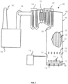
- FIG. 1 diagrammatically shows the components of a typical kraft black liquor recovery boiler system 100.
- Black liquor is a by-product of chemical pulping in the paper-making process.
- the initial concentration of "weak black liquor” is about 15%. It is concentrated to firing conditions (65% to 85% dry solids content) in an evaporator 118, and then burned in a recovery boiler 106.
- the boiler 106 has a furnace section, or "furnace 122", where the black liquor is burned, and a convective heat transfer section 104, with a bullnose 128 in-between.
- Combustion converts the black liquor's organic material into gaseous products in a series of processes involving drying, devolatilizing (pyrolyzing, molecular cracking), and char burning/gasification. Some of the organics are converted to a solid carbon particulate called char. Burning of the char occurs largely on a char bed 108 which covers the floor of the furnace 122, though some char burns in flight.
- the vertical walls 124 of the furnace are lined with vertically aligned wall tubes 126, through which water is evaporated utilizing the heat of the furnace 122.
- the furnace 122 has primary level air ports 112, secondary level air ports 114, and tertiary level air ports 120 for introducing air for combustion at three different height levels. Black liquor is sprayed into the furnace 122 out of black liquor black liquor guns 116.
- the convective heat transfer section 104 contains the following three sets of tube banks (heat traps) which successively, in stages, heat the feedwater to superheated steam: 1) an economizer 134, in which the feedwater is heated to just below its boiling point, 2) the boiler bank 132 (or “steam generating bank”), in which, along with the wall tubes 126, the water is evaporated to steam, and 3) a superheater system 130, in which a series of parallel flow elements with intermediate headers is used to increase the steam temperature from saturation to the final superheat temperature.
- tube banks heat traps
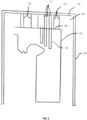
- FIG. 2 diagrammatically illustrates how the recovery boiler 106 is mounted in a steel beam support structure 208, showing only the boiler's profile and components that are of current interest.
- the entire recovery boiler 106 is suspended in the middle of the steel beam support structure 208 by boiler hanger rods 202.
- the boiler hanger rods 202 are connected between the roof 206 of the boiler 106 and the overhead beams 210 of the steel beam support structure 208.
- Another set of hanger rods hereinafter called “superheater hanger rods” or simply “hanger rods 212"
- suspend only the superheater system 130 that is, the superheater system 130 is suspended independently from the rest of the boiler 106.
- the open-air area between the boiler roof 206 and the overhead beams 210 is called the penthouse 204.
- FIG. 3 diagrammatically illustrates some of the components of the superheater system 130 which are independently suspended within the boiler 106.
- the superheater system 130 in this aspect has three superheater platen 310, 312, 314. While three superheaters are shown, it is within the terms of the invention to incorporate more superheaters as needed.
- the following discussion describes the construction of superheater platen 310 or speaks in terms of superheater platen 310, with the understanding that the construction of superheater platen 312 and superheater platen 314 is the same.
- the superheater platen 310 has typically 20-50 platens 306. Steam enters the platens 306 through a manifold tube called an inlet header 308, is superheated within the platens, and exits the platens as superheated steam through another manifold tube called an outlet header 304.
- the platens 306 are suspended from the inlet header 308 and outlet header 304, which are themselves suspended from the overhead beams 210 ( FIG. 2 ) by hanger rods 212.
- 10-20 hanger rods 212 are evenly spaced along the length of each inlet header 308 and outlet header 304, affixed by conventional means, such as welding, to the header below and to the overhead beams 210 above, as described below.
- the superheater system 130 has typically 20 hanger rods 212 -10 hanger rods for the inlet header 308 and 10 hanger rods for the outlet header 304.
- Each hanger rod has a threaded top around which a tension nut is turned to adjust the rod's tension.
- the tension of each hanger rod is adjusted typically after every 1-3 waterwashings to keep the tension uniform (balanced) among all the hanger rods 212 of a single superheater platen 310.
- each superheater platen 310 When clean (just after thorough waterwashing), each superheater platen 310 weighs typically 5000 kg, and each superheater hanger rod carries a load of typically 5000 kg . Subsequently, just before the next waterwashing is needed, deposits (fouling) add an additional weight on each superheater platen 310 of typically 2000 kg, resulting in an additional load on each hanger rod of typically 2000 kg, resulting in an additional strain on each hanger rod of typically 5.0 ⁇ 10 -5 cm/cm, which is measurable by commonly available methods, such as with a strain gage 302.
- the strain (after zeroing off the strain that was read just after the previous waterwash), summed over all the hanger rods 212 suspending a superheater platen 310, is proportional to the weight of the deposit on that superheater.
- Each additional kg of deposit yields an additional strain of typically 2.0 ⁇ 10-8 cm/cm, which is measurable by strain sensors, such as strain gage 302.
- strain sensors such as strain gage 302.
- a typical system for determining deposit weight on a single superheater platen 310 might comprise twenty (20) strain gages affixed to the twenty (20) hanger rods 212, respectively, of the superheater, a computer having data acquisition capability (not shown) connected to the 60 strain gages, and a computer program. Under the program's control, the computer periodically (typically every minute) records strain readings from the 20 strain gages (from each superheater platen 310, 312, 314), calculates the sum of the strain readings, subtracts the sum of the strain readings taken just after a previous washdown, and then multiplies the result by a calibration factor to yield the current deposit weight.
- strain gage 302 allows for the determination of the weight of the superheater platen 310, and this weight may be converted into an amount of fouling of the superheater platen 310, it is desirable to minimize the rate of fouling in order to extend the intervals between which dry cleaning and/or waterwashing is performed.
- the relationship between various boiler operating parameters and the rate of fouling is complex, so simple manual tuning of the boiler in order to minimize fouling is not efficient. What is desired are techniques for determining complex relationships between boiler operating parameters and the rate of fouling in order to determine boiler input parameters that will minimize the rate of fouling.
- FIG. 4 is a block diagram that illustrates a non-limiting example aspect of computing device components of a recovery boiler system according to various aspects of the present disclosure.
- the recovery boiler system may include a boiler controller device 402 and an analysis computing device 404.
- the boiler controller device 402 and the analysis computing device 404 can be used to determine boiler input parameters that will minimize the rate of fouling, and to implement those input parameters during operation of the recovery boiler system 100.
- the boiler controller device 402 is a computing device that electronically controls one or more components of the recovery boiler system 100.
- the boiler controller device 402 may include an ASIC, an FPGA, or another customized computing device for controlling the components of the recovery boiler system 100.
- the boiler controller device 402 may include a computing device such as a desktop computing device, a laptop computing device, a server computing device, a mobile computing device, or any other type of computing device. In some aspects, more than one computing device may be used to collectively provide the functionality described as part of the boiler controller device 402.
- the boiler controller device 402 includes at least one processor 406, a network interface 410, a boiler component interface 414, and a computer-readable medium 416.
- the network interface 410 may include any suitable communication technology for communicating with the analysis computing device 404, including but not limited to a wired communication technology (including but not limited to Ethernet, USB, and FireWire), a wireless communication technology (including but not limited to 2G, 3G, 4G, 5G, LTE, Bluetooth, ZigBee, Wi-Fi, and WiMAX), or combinations thereof.
- the boiler component interface 414 communicatively couples the boiler controller device 402 to one or more adjustable components of the recovery boiler system 100, including but not limited to the black liquor guns 116, the evaporator 118, the primary level air ports 112, the secondary level air ports 114, and the tertiary level air ports 120.
- the computer-readable medium 416 includes logic that, in response to execution by the at least one processor 406, causes the boiler controller device 402 to provide an information reporting engine 426 and an input control engine 428.
- the information reporting engine 426 receives information from one or more components of the recovery boiler system 100, and transmits the information to the analysis computing device 404.
- the input control engine 428 receives commands from the analysis computing device 404, and adjusts the adjustable components of the recovery boiler system 100 based on the commands.
- the analysis computing device 404 may include a computing device such as a desktop computing device, a laptop computing device, a mobile computing device, a server computing device, one or more computing devices of a cloud computing system, or any other type of computing device. In some aspects, more than one computing device may be used to collectively provide the functionality described as part of the analysis computing device 404.
- the analysis computing device 404 includes at least one processor 408, a network interface 412, and a computer-readable medium 418.
- the network interface 412 may include any suitable communication technology for communicating with the network interface 410 of the boiler controller device 402.
- the computer-readable medium 418 includes logic that, in response to execution by the at least one processor 408, causes the analysis computing device 404 to provide an information gathering engine 420, an analysis engine 422, and an input adjustment engine 424.
- the information gathering engine 420 receives information from at least the information reporting engine 426 of the boiler controller device 402.
- the analysis engine 422 analyzes the information gathered by the information reporting engine 426 in order to determine correlations between various boiler operating parameters and the rate of fouling.
- the input adjustment engine 424 uses the correlations determined by the analysis engine 422 in order to determine adjustments to one or more boiler input parameters, and transmits those adjustments to the boiler controller device 402 for implementation. Further details of the actions performed by each of these components are provided below.
- “computer-readable medium” refers to a removable or nonremovable device that implements any technology capable of storing information in a volatile or non-volatile manner to be read by a processor of a computing device, including but not limited to: a hard drive; a flash memory; a solid state drive; random-access memory (RAM); read-only memory (ROM); a CD-ROM, a DVD, or other disk storage; a magnetic cassette; a magnetic tape; and a magnetic disk storage.
- engine refers to logic embodied in hardware or software instructions, which can be written in a programming language, such as C, C++, COBOL, JAVA TM , PHP, Perl, HTML, CSS, JavaScript, VBScript, ASPX, Microsoft .NET TM , Go, Python, and/or the like.
- An engine may be compiled into executable programs or written in interpreted programming languages.
- Software engines may be callable from other engines or from themselves.
- the engines described herein refer to logical modules that can be merged with other engines, or can be divided into sub-engines.
- the engines can be implemented by logic stored in any type of computer-readable medium or computer storage device and be stored on and executed by one or more general purpose computers, thus creating a special purpose computer configured to provide the engine or the functionality thereof.
- the engines can be implemented by logic programmed into an application-specific integrated circuit (ASIC), a field-programmable gate array (FPGA), or another hardware device.
- ASIC application-specific integrated circuit
- FPGA field-programmable gate array
- FIG. 5 is a flowchart that illustrates a non-limiting example aspect of a method for minimizing a rate of fouling of a recovery boiler system according to various aspects of the present disclosure.
- the method 500 at least one correlation between a boiler operating parameter and the rate of fouling is determined, such that the operation of the boiler can be automatically adjusted in order to minimize the rate of fouling.
- a recovery boiler system 100 is operated by a boiler controller device 402 according to one or more boiler input parameters.
- the boiler input parameters may include any controllable aspect of operating the recovery boiler system 100.
- a chemical composition of the black liquor may be an example of a boiler input parameter.
- a chloride content of the black liquor may have an affect on a rate of fouling. Accordingly, the chloride levels could be reduced by reducing the ash recovered from the electrostatic precipitator 136, or by utilizing various technologies that selectively remove the chloride from this ash and then recycle the clean ash to the weak black liquor.
- the types of make-up chemicals could be altered to reduce the amount of chloride in the black liquor.
- a technique used to spray the black liquor may be another example of a boiler input parameter.
- the black liquor guns 116 may be adjustable via a liquor gun setting to spray the black liquor into the boiler 106 at different flow rates and/or at different droplet sizes.
- a technique used to introduce air into the boiler may be another example of a boiler input parameter.
- a setting may be adjusted in order to change the amount of air admitted by at least one of the primary level air ports 112, the secondary level air ports 114, and/or the tertiary level air ports 120, and/or to use the primary level air ports 112, the secondary level air ports 114, and/or the tertiary level air ports 120 to change air pressures in one or more locations within the boiler 106.
- a cleaning cycle of the recovery boiler system 100 is initiated and completed.
- the cleaning cycle of block 504 is being performed during operation of the recovery boiler system 100.
- a cleaning method usable during operation of the boiler 106 is sootblowing. Sootblowing may be performed by a plurality of sootblowers, which may not all be active at once. Accordingly, a "cleaning cycle" of sootblowing would include enough time such that all of the sootblowers have been activated at least once, and the entire boiler 106 has been cleaned at least once.
- more than one cleaning cycle of the recovery boiler system 100 may be completed at block 504 while the recovery boiler system 100 is being operated.
- an information reporting engine 426 of the boiler controller device 402 transmits boiler operating parameters to an information gathering engine 420 of an analysis computing device 404.
- the time period for which the boiler operating parameters are transmitted includes at least the cleaning cycle described in block 504. In some aspects, the time period may include multiple weeks or multiple months.
- the boiler operating parameters may include the boiler input parameters. In some aspects, the boiler operating parameters may also include other information regarding the operation of the recovery boiler system 100, including but not limited to temperatures of the boiler 106 in various locations, an amount of black liquor processed by the recovery boiler system 100, pressure drops through the heat transfer surfaces, and/or operating loads on the induced draft fan 138. In some aspects, the boiler operating parameters may include weight information generated by at least one strain gage 302. In some aspects, the boiler operating parameters may be provided as one or more time series of boiler operating parameter values.
- the information gathering engine 420 gathers a time series of fouling amount values.
- the information gathering engine 420 may extract the weight information received within the boiler operating parameters, and may determine the time series of fouling amount values by subtracting a tare weight of the elements suspended by the at least one strain gage 302 from each weight value.
- an analysis engine 422 of the analysis computing device 404 determines a rate of fouling based on the time series of fouling amount values. In some aspects, the rate of fouling may be determined for each step in the time series, such that changes in the rate of fouling over time can be determined.
- the analysis engine 422 performs a regression analysis on the boiler input parameters and the rate of fouling.
- the regression analysis may be configured to detect correlations between changes in the boiler input parameters and changes in the rate of fouling.
- the regression analysis may detect correlations between single boiler input parameters and changes in the rate of fouling.
- the regression analysis may detect correlations between combinations of two or more boiler input parameters and changes in the rate of fouling.
- the regression analysis may also detect correlations between one or more boiler operating parameters other than the boiler input parameters and the changes in the rate of fouling, and/or may determine additional correlations between those boiler operating parameters and the boiler input parameters.
- the regression analysis may detect a correlation between a boiler operating temperature and the rate of fouling, and an additional correlation between a liquor gun setting and the boiler operating temperature.
- CART analysis recursively partitions observations in a matched data set, comprising a categorical (for classification trees) or continuous (for regression trees) dependent (response) variable and one or more independent (explanatory) variables, into progressively smaller groups.
- Each partition may be a binary split. During each recursion, splits for each explanatory variable are examined and the split that maximizes the homogeneity of the two resulting groups with respect to the dependent variable is chosen.
- one non-limiting example approach is to divide the behavior of the boiler into times of "low-fouling" and "high-fouling,” and to develop a CART classification tree using the boiler input parameters to create homogenous groups that separate the low-fouling conditions from the high-fouling conditions. Ranges of the boiler input parameters that promote low-fouling conditions can then be selected as control ranges.
- an input adjustment engine 424 of the analysis computing device 404 determines an adjusted boiler input parameter based on a result of the regression analysis.
- the input adjustment engine 424 may use a correlation between a liquor gun setting and the rate of fouling determined by the regression analysis to determine an adjustment to the liquor gun setting.
- the input adjustment engine 424 may use a correlation between settings for one or more air ports and the rate of fouling to determine an adjustment to one or more air ports.
- the input adjustment engine 424 may use a correlation between the chemistry of the black liquor and the rate of fouling to determine an adjustment to the chemistry.
- the input adjustment engine 424 may use correlations of combined boiler input parameters with the rate of fouling to determine a combined optimal setting, or a combined optimal setting with one boiler input parameter (such as a chemistry) held constant, and may determine the adjusted boiler input parameters based on the combined optimal setting.
- the input adjustment engine 424 causes the adjusted boiler input parameter to be used by the recovery boiler system 100 to minimize fouling.
- the input adjustment engine 424 may cause the adjusted boiler input parameter to be automatically implemented by the recovery boiler system 100.
- the input adjustment engine 424 may transmit the adjusted boiler input parameter to an input control engine 428 of the boiler controller device 402, and the input control engine 428 may automatically adjust the boiler input parameters to minimize fouling.
- such adjustment of the boiler input parameters may include transmitting a command to an actuator for the black liquor guns 116 or one or more air ports in order to change a setting on the black liquor guns 116 or one or more air ports.
- such adjustment of the boiler input parameters may include transmitting commands to actuators for valves controlling the amount of precipitator ash purged or sent to the ash cleaning system of the recovery boiler to reduce chloride levels.
- the input adjustment engine 424 may present the adjusted boiler input parameter to an operator, and the operator may create commands to change settings of components of the recovery boiler system 100 to adjust the boiler input parameter as presented.
- the method 500 then proceeds to an end block and terminates.
- FIG. 6 is a block diagram that illustrates aspects of an exemplary computing device 600 appropriate for use as a computing device of the present disclosure. While multiple different types of computing devices were discussed above, the exemplary computing device 600 describes various elements that are common to many different types of computing devices. While FIG. 6 is described with reference to a computing device that is implemented as a device on a network, the description below is applicable to servers, personal computers, mobile phones, smart phones, tablet computers, embedded computing devices, and other devices that may be used to implement portions of aspects of the present disclosure. Some aspects of a computing device may be implemented in or may include an application-specific integrated circuit (ASIC), a field-programmable gate array (FPGA), or other customized device. Moreover, those of ordinary skill in the art and others will recognize that the computing device 600 may be any one of any number of currently available or yet to be developed devices.
- ASIC application-specific integrated circuit
- FPGA field-programmable gate array
- the computing device 600 includes at least one processor 602 and a system memory 604 connected by a communication bus 606.
- the system memory 604 may be volatile or nonvolatile memory, such as read only memory (“ROM”), random access memory (“RAM”), EEPROM, flash memory, or similar memory technology.
- ROM read only memory
- RAM random access memory
- EEPROM electrically erasable programmable read-only memory
- flash memory or similar memory technology.
- system memory 604 typically stores data and/or program modules that are immediately accessible to and/or currently being operated on by the processor 602.
- the processor 602 may serve as a computational center of the computing device 600 by supporting the execution of instructions.
- the computing device 600 may include a network interface 610 comprising one or more components for communicating with other devices over a network. Aspects of the present disclosure may access basic services that utilize the network interface 610 to perform communications using common network protocols.
- the network interface 610 may also include a wireless network interface configured to communicate via one or more wireless communication protocols, such as Wi-Fi, 2G, 3G, LTE, WiMAX, Bluetooth, Bluetooth low energy, and/or the like.
- the network interface 610 illustrated in FIG. 6 may represent one or more wireless interfaces or physical communication interfaces described and illustrated above with respect to particular components of the computing device 600.
- the computing device 600 also includes a storage medium 608.
- services may be accessed using a computing device that does not include means for persisting data to a local storage medium. Therefore, the storage medium 608 depicted in FIG. 6 is represented with a dashed line to indicate that the storage medium 608 is optional.
- the storage medium 608 may be volatile or nonvolatile, removable or nonremovable, implemented using any technology capable of storing information such as, but not limited to, a hard drive, solid state drive, CD ROM, DVD, or other disk storage, magnetic cassettes, magnetic tape, magnetic disk storage, and/or the like.
- FIG. 6 does not show some of the typical components of many computing devices.
- the computing device 600 may include input devices, such as a keyboard, keypad, mouse, microphone, touch input device, touch screen, tablet, and/or the like. Such input devices may be coupled to the computing device 600 by wired or wireless connections including RF, infrared, serial, parallel, Bluetooth, Bluetooth low energy, USB, or other suitable connections protocols using wireless or physical connections.
- the computing device 600 may also include output devices such as a display, speakers, printer, etc. Since these devices are well known in the art, they are not illustrated or described further herein.
- the invention describes: A system, comprising a boiler; a fouling sensor associated with a component of the boiler; a boiler controller device; and an analysis computing device that includes at least one processor and a computer-readable medium having computer-executable instructions stored thereon that, in response to execution by the at least one processor, cause the analysis computing device to perform actions comprising: receiving boiler operating information for a period of time, wherein the boiler operating information includes boiler operating parameters and a rate of fouling for the period of time, and wherein the boiler operating parameters include one or more boiler input parameters; performing a regression analysis to determine at least one correlation between the boiler operating parameters and the rate of fouling; adjusting at least one boiler input parameter based on the at least one correlation to minimize the rate of fouling; and transmitting the at least one adjusted boiler input parameter to the boiler controller device for implementation and/or preferably, wherein the boiler includes a heat exchange element, and wherein the fouling sensor is associated with the heat exchange element and/or preferably wherein the fouling sensor is a weight sensor configured to generate values indicating
- a computer-implemented method of reducing a rate of fouling in a recovery boiler system comprising: receiving, by a computing device, boiler operating information for a period of time, wherein the boiler operating information includes boiler operating parameters and a rate of fouling for the period of time, and wherein the boiler operating parameters include one or more boiler input parameters; performing, by the computing device, a regression analysis to determine at least one correlation between the boiler operating parameters and the rate of fouling; and causing, by the computing device, at least one boiler input parameter to be adjusted based on the at least one correlation to minimize the rate of fouling and/or preferably wherein receiving the rate of fouling for the period of time includes:
Landscapes
- Engineering & Computer Science (AREA)
- Mechanical Engineering (AREA)
- General Engineering & Computer Science (AREA)
- Physics & Mathematics (AREA)
- Thermal Sciences (AREA)
- Chemical & Material Sciences (AREA)
- Combustion & Propulsion (AREA)
- Control Of Steam Boilers And Waste-Gas Boilers (AREA)
- Incineration Of Waste (AREA)
- Paper (AREA)
Abstract
Description
- The invention relates to a computer-implemented method of reducing a rate of fouling in a recovery boiler system and a system configured to perform such a method.
- In some aspects, a system comprising a boiler, a fouling sensor, a boiler controller device, and an analysis computing device is provided. The fouling sensor is associated with a component of the boiler. The analysis computing device includes at least one processor and a computer-readable medium. The computer-readable medium has computer-executable instructions stored thereon that, in response to execution by the at least one processor, cause the analysis computing device to perform actions comprising receiving boiler operating information for a period of time, wherein the boiler operating information includes boiler operating parameters and a rate of fouling for the period of time; performing a regression analysis to determine at least one correlation between the boiler operating parameters and the rate of fouling; adjusting at least one boiler input parameter based on the at least one correlation to minimize the rate of fouling; and transmitting the at least one adjusted boiler input parameter to the boiler controller device for implementation.
- In some aspects, a computer-implemented method of reducing a rate of fouling in a recovery boiler system is provided. A computing device receives boiler operating information for a period of time. The boiler operating information includes boiler operating parameters and a rate of fouling for the period of time. The boiler operating parameters include one or more boiler input parameters. The computing device performs a regression analysis to determine at least one correlation between the boiler operating parameters and the rate of fouling. The computing device causes at least one boiler input parameter to be adjusted based on the at least one correlation to minimize the rate of fouling.
- In some aspects, a non-transitory computer-readable medium is provided. The medium has computer-executable instructions stored thereon that, in response to execution by one or more processors of a computing device, cause the computing device to perform actions comprising: receiving, by the computing device, boiler operating information for a period of time, wherein the boiler operating information includes boiler operating parameters and a rate of fouling for the period of time, and wherein the boiler operating parameters include one or more boiler input parameters; performing, by the computing device, a regression analysis to determine at least one correlation between the boiler operating parameters and the rate of fouling; and causing, by the computing device, at least one boiler input parameter to be adjusted based on the at least one correlation to minimize the rate of fouling.
- To easily identify the discussion of any particular element or act, the most significant digit or digits in a reference number refer to the figure number in which that element is first introduced.
-
FIG. 1 diagrammatically shows the components of a non-limiting example aspect of a kraft black liquor recovery boiler system according to various aspects of the present disclosure. -
FIG. 2 diagrammatically illustrates how the recovery boiler is mounted in a steel beam support structure according to various aspects of the present disclosure. -
FIG. 3 diagrammatically illustrates some of the components of the superheater system which are independently suspended within the boiler according to various aspects of the present disclosure. -
FIG. 4 is a block diagram that illustrates a non-limiting example aspect of computing device components of a recovery boiler system according to various aspects of the present disclosure. -
FIG. 5 is a flowchart that illustrates a non-limiting example aspect of a method for minimizing a rate of fouling of a recovery boiler system according to various aspects of the present disclosure. -
FIG. 6 is a block diagram that illustrates a non-limiting example aspect of a computing device appropriate for use as a computing device with aspects of the present disclosure. - In the paper-making process, chemical pulping yields, as a by-product, black liquor, which contains almost all of the inorganic cooking chemicals along with the lignin and other organic matter separated from the wood during pulping in a digester. The black liquor is burned in a recovery boiler. The two main functions of the recovery boiler are to recover the inorganic cooking chemicals used in the pulping process and to make use of the chemical energy in the organic portion of the black liquor to generate steam for a paper mill. The twin objectives of recovering both chemicals and energy make recovery boiler design and operation very complex.
- In a kraft recovery boiler, superheaters are placed in the upper furnace in order to extract heat by radiation and convection from the furnace gases. Saturated steam enters the superheater section, and superheated steam exits at a controlled temperature. The superheater is constructed of an array of tube panels. The superheater surface is continually being fouled by ash that is being carried out of the furnace chamber. The amount of black liquor that can be burned in a kraft recovery boiler is often limited by the rate and extent of fouling on the surfaces of the superheater. This fouling reduces the heat absorbed from the liquor combustion, resulting in low exit steam temperatures from the superheaters and high gas temperatures entering the boiler. The boiler is shutdown for cleaning when either the exit steam temperature is too low for use in downstream equipment or the temperature entering the boiler bank exceeds the melting temperature of the deposits, resulting in gas side pluggage of the boiler bank. Kraft recovery boilers are particularly prone to the problem of superheater fouling, due to the high quantity of ash in the fuel (typically more than 35%) and the low melting temperature of the ash.
- There are three conventional methods of removing deposits from the superheaters in kraft recovery boilers, listed in increasing order of required down-time and decreasing order of frequency: 1) sootblowing; 2) chill-and-blow; and 3) waterwashing.
- Sootblowing is the process of blowing ash deposit off the superheater with a blast of steam from nozzles called sootblowers. Sootblowing occurs essentially continuously during normal boiler operation, with different sootblowers turned on at different times. Sootblowing reduces boiler efficiency, since 5-10% of the boiler's steam is typically used for sootblowing. Each sootblowing operation reduces a portion of the nearby ash deposit, but the ash deposit nevertheless continues to build up over time. As the deposit grows, sootblowing becomes gradually less effective and results in impairment of the heat transfer.
- When the ash deposit reaches a certain threshold where boiler efficiency is significantly reduced and sootblowing is insufficiently effective, deposits are removed by the second cleaning process called "chill-and-blow" (also called "dry cleaning" because water is not used), requiring the partial or complete cessation of fuel firing in the boiler for typically 4-12 hours, but not complete boiler shutdown. During this time, the sootblowers continuously operate to cause the deposits to debond from the superheater sections and fall to the floor of the boiler. This procedure may be performed as often as every month, but the frequency can be reduced if the sootblowing is performed optimally (at the optimum schedule and in the optimum sequence). As with sootblowing, the chill-and-blow procedure reduces a portion of the nearby ash deposit, but the ash deposit nevertheless continues to grow over time. As the deposit grows, the chill-and-blow procedure becomes gradually less effective and must be performed more often.
- The third cleaning process, waterwashing, entails complete boiler shutdown for typically two days, causing significant loss in pulping capacity at a mill. In a heavily fouled recovery boiler, it may be required every four months, but if the chill-and-blow process is properly timed (i.e. before large deposits form in the boiler bank section), then the shutdown and waterwashing can be avoided for even a year or longer.
- As each of these cleaning processes reduces the efficiency of the boiler or entails shutdown of the boiler, it is clear that it is desirable to minimize the time spent during the cleaning processes. What is desired is an effective technique for adjusting operation of the boiler. This is maybe achieved in such a way that fouling of the boiler is minimized, and thereby the amount of time spent or parasitic energy used executing one or more of these cleaning processes is reduced.
-
FIG. 1 diagrammatically shows the components of a typical kraft black liquorrecovery boiler system 100. Black liquor is a by-product of chemical pulping in the paper-making process. The initial concentration of "weak black liquor" is about 15%. It is concentrated to firing conditions (65% to 85% dry solids content) in anevaporator 118, and then burned in arecovery boiler 106. - The
boiler 106 has a furnace section, or "furnace 122", where the black liquor is burned, and a convectiveheat transfer section 104, with abullnose 128 in-between. Combustion converts the black liquor's organic material into gaseous products in a series of processes involving drying, devolatilizing (pyrolyzing, molecular cracking), and char burning/gasification. Some of the organics are converted to a solid carbon particulate called char. Burning of the char occurs largely on achar bed 108 which covers the floor of thefurnace 122, though some char burns in flight. As carbon in the char is gasified or burned, the inorganic compounds in the char are released and form a molten salt mixture called smelt, which flows to the bottom of thechar bed 108, and is continuously tapped from thefurnace 122 throughsmelt spouts 110. Exhaust gases pass through an induceddraft fan 138 and are filtered through anelectrostatic precipitator 136, and exit through astack 102. - The
vertical walls 124 of the furnace are lined with vertically alignedwall tubes 126, through which water is evaporated utilizing the heat of thefurnace 122. Thefurnace 122 has primarylevel air ports 112, secondarylevel air ports 114, and tertiarylevel air ports 120 for introducing air for combustion at three different height levels. Black liquor is sprayed into thefurnace 122 out of black liquorblack liquor guns 116. - The convective
heat transfer section 104 contains the following three sets of tube banks (heat traps) which successively, in stages, heat the feedwater to superheated steam: 1) aneconomizer 134, in which the feedwater is heated to just below its boiling point, 2) the boiler bank 132 (or "steam generating bank"), in which, along with thewall tubes 126, the water is evaporated to steam, and 3) asuperheater system 130, in which a series of parallel flow elements with intermediate headers is used to increase the steam temperature from saturation to the final superheat temperature. -
FIG. 2 diagrammatically illustrates how therecovery boiler 106 is mounted in a steelbeam support structure 208, showing only the boiler's profile and components that are of current interest. Theentire recovery boiler 106 is suspended in the middle of the steelbeam support structure 208 byboiler hanger rods 202. Theboiler hanger rods 202 are connected between theroof 206 of theboiler 106 and theoverhead beams 210 of the steelbeam support structure 208. Another set of hanger rods, hereinafter called "superheater hanger rods" or simply "hanger rods 212", suspend only thesuperheater system 130. That is, thesuperheater system 130 is suspended independently from the rest of theboiler 106. The open-air area between theboiler roof 206 and theoverhead beams 210 is called thepenthouse 204. -
FIG. 3 diagrammatically illustrates some of the components of thesuperheater system 130 which are independently suspended within theboiler 106. Thesuperheater system 130 in this aspect has threesuperheater platen superheater platen 310 or speaks in terms ofsuperheater platen 310, with the understanding that the construction ofsuperheater platen 312 andsuperheater platen 314 is the same. - The
superheater platen 310 has typically 20-50platens 306. Steam enters theplatens 306 through a manifold tube called aninlet header 308, is superheated within the platens, and exits the platens as superheated steam through another manifold tube called anoutlet header 304. Theplatens 306 are suspended from theinlet header 308 andoutlet header 304, which are themselves suspended from the overhead beams 210 (FIG. 2 ) byhanger rods 212. Typically 10-20hanger rods 212 are evenly spaced along the length of eachinlet header 308 andoutlet header 304, affixed by conventional means, such as welding, to the header below and to theoverhead beams 210 above, as described below. Thesuperheater system 130 has typically 20 hanger rods 212 -10 hanger rods for theinlet header 308 and 10 hanger rods for theoutlet header 304. Each hanger rod has a threaded top around which a tension nut is turned to adjust the rod's tension. The tension of each hanger rod is adjusted typically after every 1-3 waterwashings to keep the tension uniform (balanced) among all thehanger rods 212 of asingle superheater platen 310. - When clean (just after thorough waterwashing), each
superheater platen 310 weighs typically 5000 kg, and each superheater hanger rod carries a load of typically 5000 kg . Subsequently, just before the next waterwashing is needed, deposits (fouling) add an additional weight on eachsuperheater platen 310 of typically 2000 kg, resulting in an additional load on each hanger rod of typically 2000 kg, resulting in an additional strain on each hanger rod of typically 5.0×10⁻⁵ cm/cm, which is measurable by commonly available methods, such as with astrain gage 302. - The strain (after zeroing off the strain that was read just after the previous waterwash), summed over all the
hanger rods 212 suspending asuperheater platen 310, is proportional to the weight of the deposit on that superheater. Each additional kg of deposit yields an additional strain of typically 2.0×10⁻⁸ cm/cm, which is measurable by strain sensors, such asstrain gage 302. Hence, the weight of the deposit on eachsuperheater platen 310 can be directly determined by measuring the strain on itscorresponding hanger rods 212. - A typical system for determining deposit weight on a
single superheater platen 310 might comprise twenty (20) strain gages affixed to the twenty (20)hanger rods 212, respectively, of the superheater, a computer having data acquisition capability (not shown) connected to the 60 strain gages, and a computer program. Under the program's control, the computer periodically (typically every minute) records strain readings from the 20 strain gages (from eachsuperheater platen - In equation form, the formula is:

- or, equivalently stated:

- where
- ΣSt=Sum of strain gage readings at any time t
- ΣSo=Sum of strain gage readings just after a previous waterwash, considered as at time zero.
- C=calibration constant to convert strain to weight.
- While the
strain gage 302 allows for the determination of the weight of thesuperheater platen 310, and this weight may be converted into an amount of fouling of thesuperheater platen 310, it is desirable to minimize the rate of fouling in order to extend the intervals between which dry cleaning and/or waterwashing is performed. The relationship between various boiler operating parameters and the rate of fouling is complex, so simple manual tuning of the boiler in order to minimize fouling is not efficient. What is desired are techniques for determining complex relationships between boiler operating parameters and the rate of fouling in order to determine boiler input parameters that will minimize the rate of fouling. -
FIG. 4 is a block diagram that illustrates a non-limiting example aspect of computing device components of a recovery boiler system according to various aspects of the present disclosure. As shown, the recovery boiler system may include aboiler controller device 402 and ananalysis computing device 404. Theboiler controller device 402 and theanalysis computing device 404 can be used to determine boiler input parameters that will minimize the rate of fouling, and to implement those input parameters during operation of therecovery boiler system 100. - In some aspects, the
boiler controller device 402 is a computing device that electronically controls one or more components of therecovery boiler system 100. In some aspects, theboiler controller device 402 may include an ASIC, an FPGA, or another customized computing device for controlling the components of therecovery boiler system 100. In some aspects, theboiler controller device 402 may include a computing device such as a desktop computing device, a laptop computing device, a server computing device, a mobile computing device, or any other type of computing device. In some aspects, more than one computing device may be used to collectively provide the functionality described as part of theboiler controller device 402. - As shown, the
boiler controller device 402 includes at least oneprocessor 406, anetwork interface 410, aboiler component interface 414, and a computer-readable medium 416. In some aspects, thenetwork interface 410 may include any suitable communication technology for communicating with theanalysis computing device 404, including but not limited to a wired communication technology (including but not limited to Ethernet, USB, and FireWire), a wireless communication technology (including but not limited to 2G, 3G, 4G, 5G, LTE, Bluetooth, ZigBee, Wi-Fi, and WiMAX), or combinations thereof. In some aspects, theboiler component interface 414 communicatively couples theboiler controller device 402 to one or more adjustable components of therecovery boiler system 100, including but not limited to theblack liquor guns 116, theevaporator 118, the primarylevel air ports 112, the secondarylevel air ports 114, and the tertiarylevel air ports 120. - As shown, the computer-
readable medium 416 includes logic that, in response to execution by the at least oneprocessor 406, causes theboiler controller device 402 to provide aninformation reporting engine 426 and aninput control engine 428. In some aspects, theinformation reporting engine 426 receives information from one or more components of therecovery boiler system 100, and transmits the information to theanalysis computing device 404. In some aspects, theinput control engine 428 receives commands from theanalysis computing device 404, and adjusts the adjustable components of therecovery boiler system 100 based on the commands. - In some aspects, the
analysis computing device 404 may include a computing device such as a desktop computing device, a laptop computing device, a mobile computing device, a server computing device, one or more computing devices of a cloud computing system, or any other type of computing device. In some aspects, more than one computing device may be used to collectively provide the functionality described as part of theanalysis computing device 404. - As shown, the
analysis computing device 404 includes at least oneprocessor 408, anetwork interface 412, and a computer-readable medium 418. In some aspects, thenetwork interface 412 may include any suitable communication technology for communicating with thenetwork interface 410 of theboiler controller device 402. - As shown, the computer-
readable medium 418 includes logic that, in response to execution by the at least oneprocessor 408, causes theanalysis computing device 404 to provide aninformation gathering engine 420, ananalysis engine 422, and aninput adjustment engine 424. In some aspects, theinformation gathering engine 420 receives information from at least theinformation reporting engine 426 of theboiler controller device 402. In some aspects, theanalysis engine 422 analyzes the information gathered by theinformation reporting engine 426 in order to determine correlations between various boiler operating parameters and the rate of fouling. In some aspects, theinput adjustment engine 424 uses the correlations determined by theanalysis engine 422 in order to determine adjustments to one or more boiler input parameters, and transmits those adjustments to theboiler controller device 402 for implementation. Further details of the actions performed by each of these components are provided below. - "computer-readable medium" refers to a removable or nonremovable device that implements any technology capable of storing information in a volatile or non-volatile manner to be read by a processor of a computing device, including but not limited to: a hard drive; a flash memory; a solid state drive; random-access memory (RAM); read-only memory (ROM); a CD-ROM, a DVD, or other disk storage; a magnetic cassette; a magnetic tape; and a magnetic disk storage.
- "engine" refers to logic embodied in hardware or software instructions, which can be written in a programming language, such as C, C++, COBOL, JAVA™, PHP, Perl, HTML, CSS, JavaScript, VBScript, ASPX, Microsoft .NET™, Go, Python, and/or the like. An engine may be compiled into executable programs or written in interpreted programming languages. Software engines may be callable from other engines or from themselves. Generally, the engines described herein refer to logical modules that can be merged with other engines, or can be divided into sub-engines. The engines can be implemented by logic stored in any type of computer-readable medium or computer storage device and be stored on and executed by one or more general purpose computers, thus creating a special purpose computer configured to provide the engine or the functionality thereof. The engines can be implemented by logic programmed into an application-specific integrated circuit (ASIC), a field-programmable gate array (FPGA), or another hardware device.
-
FIG. 5 is a flowchart that illustrates a non-limiting example aspect of a method for minimizing a rate of fouling of a recovery boiler system according to various aspects of the present disclosure. In themethod 500, at least one correlation between a boiler operating parameter and the rate of fouling is determined, such that the operation of the boiler can be automatically adjusted in order to minimize the rate of fouling. - From a start block, the
method 500 proceeds to block 502, where arecovery boiler system 100 is operated by aboiler controller device 402 according to one or more boiler input parameters. In some aspects, the boiler input parameters may include any controllable aspect of operating therecovery boiler system 100. In some aspects, a chemical composition of the black liquor may be an example of a boiler input parameter. For example, a chloride content of the black liquor may have an affect on a rate of fouling. Accordingly, the chloride levels could be reduced by reducing the ash recovered from theelectrostatic precipitator 136, or by utilizing various technologies that selectively remove the chloride from this ash and then recycle the clean ash to the weak black liquor. In some aspects, the types of make-up chemicals could be altered to reduce the amount of chloride in the black liquor. In some aspects, a technique used to spray the black liquor may be another example of a boiler input parameter. For example, theblack liquor guns 116 may be adjustable via a liquor gun setting to spray the black liquor into theboiler 106 at different flow rates and/or at different droplet sizes. - In some aspects, a technique used to introduce air into the boiler may be another example of a boiler input parameter. For example, a setting may be adjusted in order to change the amount of air admitted by at least one of the primary
level air ports 112, the secondarylevel air ports 114, and/or the tertiarylevel air ports 120, and/or to use the primarylevel air ports 112, the secondarylevel air ports 114, and/or the tertiarylevel air ports 120 to change air pressures in one or more locations within theboiler 106. - At
block 504, a cleaning cycle of therecovery boiler system 100 is initiated and completed. In some aspects, the cleaning cycle ofblock 504 is being performed during operation of therecovery boiler system 100. As discussed above, a cleaning method usable during operation of theboiler 106 is sootblowing. Sootblowing may be performed by a plurality of sootblowers, which may not all be active at once. Accordingly, a "cleaning cycle" of sootblowing would include enough time such that all of the sootblowers have been activated at least once, and theentire boiler 106 has been cleaned at least once. By allowing a complete cleaning cycle to be completed, enough information will be collected to compensate for any short-term anomalies in the detected fouling rate due to unequal effectiveness of individual sootblowers. In some aspects, more than one cleaning cycle of therecovery boiler system 100 may be completed atblock 504 while therecovery boiler system 100 is being operated. - At
block 506, during operation and cleaning of therecovery boiler system 100, aninformation reporting engine 426 of theboiler controller device 402 transmits boiler operating parameters to aninformation gathering engine 420 of ananalysis computing device 404. The time period for which the boiler operating parameters are transmitted includes at least the cleaning cycle described inblock 504. In some aspects, the time period may include multiple weeks or multiple months. - In some aspects, the boiler operating parameters may include the boiler input parameters. In some aspects, the boiler operating parameters may also include other information regarding the operation of the
recovery boiler system 100, including but not limited to temperatures of theboiler 106 in various locations, an amount of black liquor processed by therecovery boiler system 100, pressure drops through the heat transfer surfaces, and/or operating loads on the induceddraft fan 138. In some aspects, the boiler operating parameters may include weight information generated by at least onestrain gage 302. In some aspects, the boiler operating parameters may be provided as one or more time series of boiler operating parameter values. - At
block 508, during operation and cleaning of therecovery boiler system 100, theinformation gathering engine 420 gathers a time series of fouling amount values. In some aspects, theinformation gathering engine 420 may extract the weight information received within the boiler operating parameters, and may determine the time series of fouling amount values by subtracting a tare weight of the elements suspended by the at least onestrain gage 302 from each weight value. Atblock 510, ananalysis engine 422 of theanalysis computing device 404 determines a rate of fouling based on the time series of fouling amount values. In some aspects, the rate of fouling may be determined for each step in the time series, such that changes in the rate of fouling over time can be determined. - At
block 512, theanalysis engine 422 performs a regression analysis on the boiler input parameters and the rate of fouling. In some aspects, the regression analysis may be configured to detect correlations between changes in the boiler input parameters and changes in the rate of fouling. In some aspects, the regression analysis may detect correlations between single boiler input parameters and changes in the rate of fouling. In some aspects, the regression analysis may detect correlations between combinations of two or more boiler input parameters and changes in the rate of fouling. In some aspects, the regression analysis may also detect correlations between one or more boiler operating parameters other than the boiler input parameters and the changes in the rate of fouling, and/or may determine additional correlations between those boiler operating parameters and the boiler input parameters. For example, the regression analysis may detect a correlation between a boiler operating temperature and the rate of fouling, and an additional correlation between a liquor gun setting and the boiler operating temperature. - Any suitable regression analysis, including but not limited to a classification and regression tree (CART) analysis, may be used. In some aspects, CART analysis recursively partitions observations in a matched data set, comprising a categorical (for classification trees) or continuous (for regression trees) dependent (response) variable and one or more independent (explanatory) variables, into progressively smaller groups. Each partition may be a binary split. During each recursion, splits for each explanatory variable are examined and the split that maximizes the homogeneity of the two resulting groups with respect to the dependent variable is chosen. When examining boiler input parameters and the rate of fouling, one non-limiting example approach is to divide the behavior of the boiler into times of "low-fouling" and "high-fouling," and to develop a CART classification tree using the boiler input parameters to create homogenous groups that separate the low-fouling conditions from the high-fouling conditions. Ranges of the boiler input parameters that promote low-fouling conditions can then be selected as control ranges.
- At
block 514, aninput adjustment engine 424 of theanalysis computing device 404 determines an adjusted boiler input parameter based on a result of the regression analysis. For example, theinput adjustment engine 424 may use a correlation between a liquor gun setting and the rate of fouling determined by the regression analysis to determine an adjustment to the liquor gun setting. As another example, theinput adjustment engine 424 may use a correlation between settings for one or more air ports and the rate of fouling to determine an adjustment to one or more air ports. As yet another example, theinput adjustment engine 424 may use a correlation between the chemistry of the black liquor and the rate of fouling to determine an adjustment to the chemistry. As still another example, theinput adjustment engine 424 may use correlations of combined boiler input parameters with the rate of fouling to determine a combined optimal setting, or a combined optimal setting with one boiler input parameter (such as a chemistry) held constant, and may determine the adjusted boiler input parameters based on the combined optimal setting. - At
block 516, theinput adjustment engine 424 causes the adjusted boiler input parameter to be used by therecovery boiler system 100 to minimize fouling. In some aspects, theinput adjustment engine 424 may cause the adjusted boiler input parameter to be automatically implemented by therecovery boiler system 100. For example, theinput adjustment engine 424 may transmit the adjusted boiler input parameter to aninput control engine 428 of theboiler controller device 402, and theinput control engine 428 may automatically adjust the boiler input parameters to minimize fouling. In some aspects, such adjustment of the boiler input parameters may include transmitting a command to an actuator for theblack liquor guns 116 or one or more air ports in order to change a setting on theblack liquor guns 116 or one or more air ports. In some aspects, such adjustment of the boiler input parameters may include transmitting commands to actuators for valves controlling the amount of precipitator ash purged or sent to the ash cleaning system of the recovery boiler to reduce chloride levels. In some aspects, instead of causing the adjusted boiler input parameter to be automatically implemented, theinput adjustment engine 424 may present the adjusted boiler input parameter to an operator, and the operator may create commands to change settings of components of therecovery boiler system 100 to adjust the boiler input parameter as presented. - The
method 500 then proceeds to an end block and terminates. -
FIG. 6 is a block diagram that illustrates aspects of anexemplary computing device 600 appropriate for use as a computing device of the present disclosure. While multiple different types of computing devices were discussed above, theexemplary computing device 600 describes various elements that are common to many different types of computing devices. WhileFIG. 6 is described with reference to a computing device that is implemented as a device on a network, the description below is applicable to servers, personal computers, mobile phones, smart phones, tablet computers, embedded computing devices, and other devices that may be used to implement portions of aspects of the present disclosure. Some aspects of a computing device may be implemented in or may include an application-specific integrated circuit (ASIC), a field-programmable gate array (FPGA), or other customized device. Moreover, those of ordinary skill in the art and others will recognize that thecomputing device 600 may be any one of any number of currently available or yet to be developed devices. - In its most basic configuration, the
computing device 600 includes at least oneprocessor 602 and asystem memory 604 connected by a communication bus 606. Depending on the exact configuration and type of device, thesystem memory 604 may be volatile or nonvolatile memory, such as read only memory ("ROM"), random access memory ("RAM"), EEPROM, flash memory, or similar memory technology. Those of ordinary skill in the art and others will recognize thatsystem memory 604 typically stores data and/or program modules that are immediately accessible to and/or currently being operated on by theprocessor 602. In this regard, theprocessor 602 may serve as a computational center of thecomputing device 600 by supporting the execution of instructions. - As further illustrated in
FIG. 6 , thecomputing device 600 may include anetwork interface 610 comprising one or more components for communicating with other devices over a network. Aspects of the present disclosure may access basic services that utilize thenetwork interface 610 to perform communications using common network protocols. Thenetwork interface 610 may also include a wireless network interface configured to communicate via one or more wireless communication protocols, such as Wi-Fi, 2G, 3G, LTE, WiMAX, Bluetooth, Bluetooth low energy, and/or the like. As will be appreciated by one of ordinary skill in the art, thenetwork interface 610 illustrated inFIG. 6 may represent one or more wireless interfaces or physical communication interfaces described and illustrated above with respect to particular components of thecomputing device 600. - In the exemplary aspect depicted in
FIG. 6 , thecomputing device 600 also includes astorage medium 608. However, services may be accessed using a computing device that does not include means for persisting data to a local storage medium. Therefore, thestorage medium 608 depicted inFIG. 6 is represented with a dashed line to indicate that thestorage medium 608 is optional. In any event, thestorage medium 608 may be volatile or nonvolatile, removable or nonremovable, implemented using any technology capable of storing information such as, but not limited to, a hard drive, solid state drive, CD ROM, DVD, or other disk storage, magnetic cassettes, magnetic tape, magnetic disk storage, and/or the like. - Suitable implementations of computing devices that include a
processor 602,system memory 604, communication bus 606,storage medium 608, andnetwork interface 610 are known and commercially available. For ease of illustration and because it is not important for an understanding of the claimed subject matter,FIG. 6 does not show some of the typical components of many computing devices. In this regard, thecomputing device 600 may include input devices, such as a keyboard, keypad, mouse, microphone, touch input device, touch screen, tablet, and/or the like. Such input devices may be coupled to thecomputing device 600 by wired or wireless connections including RF, infrared, serial, parallel, Bluetooth, Bluetooth low energy, USB, or other suitable connections protocols using wireless or physical connections. Similarly, thecomputing device 600 may also include output devices such as a display, speakers, printer, etc. Since these devices are well known in the art, they are not illustrated or described further herein. - In the foregoing description numerous specific details are set forth to provide a thorough understanding of the aspects. One skilled in the relevant art will recognize, however, that the techniques described herein can be practiced without one or more of the specific details, or with other methods, components, materials, etc. In other instances, well-known structures, materials, or operations are not shown or described in detail to avoid obscuring certain aspects.
- The order in which some or all of the process blocks appear in each process should not be deemed limiting. Rather, one of ordinary skill in the art having the benefit of the present disclosure will understand that some of the process blocks may be executed in a variety of orders not illustrated, or even in parallel.
- The above description of illustrated aspects of the invention, including what is described in the Abstract, is not intended to be exhaustive or to limit the invention to the precise forms disclosed. While specific aspects of, and examples for, the invention are described herein for illustrative purposes, various modifications are possible within the scope of the invention, as those skilled in the relevant art will recognize.
- These modifications can be made to the invention in light of the above detailed description. The terms used in the following claims should not be construed to limit the invention to the specific aspects disclosed in the specification. Rather, the scope of the invention is to be determined entirely by the following claims, which are to be construed in accordance with established doctrines of claim interpretation.
- In general, the invention describes:
A system, comprising a boiler; a fouling sensor associated with a component of the boiler; a boiler controller device; and an analysis computing device that includes at least one processor and a computer-readable medium having computer-executable instructions stored thereon that, in response to execution by the at least one processor, cause the analysis computing device to perform actions comprising: receiving boiler operating information for a period of time, wherein the boiler operating information includes boiler operating parameters and a rate of fouling for the period of time, and wherein the boiler operating parameters include one or more boiler input parameters; performing a regression analysis to determine at least one correlation between the boiler operating parameters and the rate of fouling; adjusting at least one boiler input parameter based on the at least one correlation to minimize the rate of fouling; and transmitting the at least one adjusted boiler input parameter to the boiler controller device for implementation and/or preferably, wherein the boiler includes a heat exchange element, and wherein the fouling sensor is associated with the heat exchange element and/or preferably wherein the fouling sensor is a weight sensor configured to generate values indicating a weight of the heat exchange element and/or preferably wherein receiving the rate of fouling for the period of time includes: receiving a time series of fouling amount values; and determining the rate of fouling based on the time series of fouling amount values and/or preferably wherein performing the regression analysis to determine the at least one correlation between the boiler operating parameters and the rate of fouling includes performing a CART analysis on the boiler operating information and/or preferably further comprising one or more sootblowers configured to operate according to a cycle, and wherein receiving boiler operating information for the period of time includes receiving boiler operating information for a period of time that includes at least one complete cycle and/or preferably further comprising: one or more valves configured to control an amount of precipitator ash purged or sent to an ash cleaning system in order to affect a chloride level; and one or more actuators configured to control the one or more valves; wherein the at least one boiler input parameter includes a valve setting; wherein transmitting the at least one adjusted boiler input parameter to the boiler controller device for implementation includes transmitting the valve setting to the one or more actuators; and wherein the one or more actuators are configured to adjust the one or more valves based on the valve setting; and/or preferably further comprising one or more liquor guns, wherein the at least one boiler input parameter includes a liquor gun setting, wherein transmitting the at least one adjusted boiler input parameter to the boiler controller device for implementation includes transmitting the liquor gun setting to the boiler controller device, and wherein the boiler controller device is configured to change operation of the one or more liquor guns based on the liquor gun setting and/or preferably further comprising one or more air ports, wherein the at least one boiler input parameter includes settings for one or more air ports, wherein transmitting the at least one adjusted boiler input parameter to the boiler controller device for implementation includes transmitting adjusted settings for one or more air ports to the boiler controller device, and wherein the boiler controller device is configured to change operation of the one or more air ports based on the adjusted settings for the one or more air ports. - A computer-implemented method of reducing a rate of fouling in a recovery boiler system, the method comprising: receiving, by a computing device, boiler operating information for a period of time, wherein the boiler operating information includes boiler operating parameters and a rate of fouling for the period of time, and wherein the boiler operating parameters include one or more boiler input parameters; performing, by the computing device, a regression analysis to determine at least one correlation between the boiler operating parameters and the rate of fouling; and causing, by the computing device, at least one boiler input parameter to be adjusted based on the at least one correlation to minimize the rate of fouling and/or preferably wherein receiving the rate of fouling for the period of time includes:
- receiving, by the computing device, a time series of fouling amount values; and
- determining, by the computing device, the rate of fouling based on the time series of fouling amount values; and/or preferably wherein receiving the time series of fouling amount values includes receiving the time series of fouling amount values from a weight sensor configured to weigh a heat exchange element and/or preferably wherein
- performing the regression analysis to determine the at least one correlation between the boiler operating parameters and the rate of fouling includes performing a CART analysis on the boiler operating information and/or preferably wherein the recovery boiler system includes one or more sootblowers configured to operate according to a cycle, and
- wherein receiving boiler operating information for the period of time includes receiving boiler operating information for a period of time that includes at least one complete cycle and/or preferably wherein causing the at least one boiler input parameter to be adjusted based on the at least one correlation to minimize the rate of fouling includes at least one of causing a chemistry of boiler inputs to be adjusted, causing a liquor gun setting to be adjusted, and causing settings for one or more air ports to be adjusted.
- A non-transitory computer-readable medium having computer-executable instructions stored thereon that, in response to execution by one or more processors of a computing device, cause the computing device to perform actions comprising: receiving, by the computing device, boiler operating information for a period of time, wherein the boiler operating information includes boiler operating parameters and a rate of fouling for the period of time, and wherein the boiler operating parameters include one or more boiler input parameters; performing, by the computing device, a regression analysis to determine at least one correlation between the boiler operating parameters and the rate of fouling; and causing, by the computing device, at least one boiler input parameter to be adjusted based on the at least one correlation to minimize the rate of fouling, and/or preferably wherein receiving the rate of fouling for the period of time includes: receiving, by the computing device, a time series of fouling amount values; and determining, by the computing device, the rate of fouling based on the time series of fouling amount values and/or preferably wherein performing the regression analysis to determine the at least one correlation between the boiler operating parameters and the rate of fouling includes performing a CART analysis on the boiler operating information and/or preferably wherein the recovery boiler system includes one or more sootblowers configured to operate according to a cycle, and wherein receiving boiler operating information for a period of time includes receiving boiler operating information for a period of time that includes at least one complete cycle and/or preferably wherein causing the at least one boiler input parameter to be adjusted based on the at least one correlation to minimize the rate of fouling includes at least one of causing a chemistry of boiler inputs to be adjusted, causing a liquor gun setting to be adjusted, and causing settings for one or more air ports to be adjusted.
Although the present invention is defined in the claims, it should be understood that the present invention can also (alternatively) be defined in accordance with the following embodiments: - 1. A system, comprising:
- a boiler;
- a fouling sensor associated with a component of the boiler;
- a boiler controller device; and
- an analysis computing device that includes at least one processor and a computer-readable medium having computer-executable instructions stored thereon that, in response to execution by the at least one processor, cause the analysis computing device to perform actions comprising:
- receiving boiler operating information for a period of time, wherein the boiler operating information includes boiler operating parameters and a rate of fouling for the period of time, and wherein the boiler operating parameters include one or more boiler input parameters;
- performing a regression analysis to determine at least one correlation between the boiler operating parameters and the rate of fouling;
- adjusting at least one boiler input parameter based on the at least one correlation to minimize the rate of fouling; and
- transmitting the at least one adjusted boiler input parameter to the boiler controller device for implementation.
- 2. The system of embodiment 1, wherein the boiler includes a heat exchange element, and wherein the fouling sensor is associated with the heat exchange element.
- 3. The system of embodiment 2, wherein the fouling sensor is a weight sensor configured to generate values indicating a weight of the heat exchange element.
- 4. The system of embodiment 1, wherein receiving the rate of fouling for the period of time includes:
- receiving a time series of fouling amount values; and
- determining the rate of fouling based on the time series of fouling amount values.
- 5. The system of embodiment 1, wherein performing the regression analysis to determine the at least one correlation between the boiler operating parameters and the rate of fouling includes performing a CART analysis on the boiler operating information.
- 6. The system of embodiment 1, further comprising one or more sootblowers configured to operate according to a cycle, and wherein receiving boiler operating information for the period of time includes receiving boiler operating information for a period of time that includes at least one complete cycle.
- 7. The system of embodiment 1, further comprising:
- one or more valves configured to control an amount of precipitator ash purged or sent to an ash cleaning system in order to affect a chloride level; and
- one or more actuators configured to control the one or more valves;
- wherein the at least one boiler input parameter includes a valve setting;
- wherein transmitting the at least one adjusted boiler input parameter to the boiler controller device for implementation includes transmitting the valve setting to the one or more actuators; and
- wherein the one or more actuators are configured to adjust the one or more valves based on the valve setting.
- 8. The system of embodiment 1, further comprising one or more liquor guns, wherein the at least one boiler input parameter includes a liquor gun setting, wherein transmitting the at least one adjusted boiler input parameter to the boiler controller device for implementation includes transmitting the liquor gun setting to the boiler controller device, and wherein the boiler controller device is configured to change operation of the one or more liquor guns based on the liquor gun setting.
- 9. The system of embodiment 1, further comprising one or more air ports, wherein the at least one boiler input parameter includes settings for one or more air ports, wherein transmitting the at least one adjusted boiler input parameter to the boiler controller device for implementation includes transmitting adjusted settings for one or more air ports to the boiler controller device, and wherein the boiler controller device is configured to change operation of the one or more air ports based on the adjusted settings for the one or more air ports.
- 10. A computer-implemented method of reducing a rate of fouling in a recovery boiler system, the method comprising:
- receiving, by a computing device, boiler operating information for a period of time, wherein the boiler operating information includes boiler operating parameters and a rate of fouling for the period of time, and wherein the boiler operating parameters include one or more boiler input parameters;
- performing, by the computing device, a regression analysis to determine at least one correlation between the boiler operating parameters and the rate of fouling; and
- causing, by the computing device, at least one boiler input parameter to be adjusted based on the at least one correlation to minimize the rate of fouling.
- 11. The computer-implemented method of embodiment 10, wherein receiving the rate of fouling for the period of time includes:
- receiving, by the computing device, a time series of fouling amount values; and
- determining, by the computing device, the rate of fouling based on the time series of fouling amount values.
- 12. The computer-implemented method of embodiment 11, wherein receiving the time series of fouling amount values includes receiving the time series of fouling amount values from a weight sensor configured to weigh a heat exchange element.
- 13. The computer-implemented method of embodiment 10, wherein performing the regression analysis to determine the at least one correlation between the boiler operating parameters and the rate of fouling includes performing a CART analysis on the boiler operating information.
- 14. The computer-implemented method of embodiment 10, wherein the recovery boiler system includes one or more sootblowers configured to operate according to a cycle, and wherein receiving boiler operating information for the period of time includes receiving boiler operating information for a period of time that includes at least one complete cycle.
- 15. The computer-implemented method of embodiment 10, wherein causing the at least one boiler input parameter to be adjusted based on the at least one correlation to minimize the rate of fouling includes at least one of causing a chemistry of boiler inputs to be adjusted, causing a liquor gun setting to be adjusted, and causing settings for one or more air ports to be adjusted.
- 16. A non-transitory computer-readable medium having computer-executable instructions stored thereon that, in response to execution by one or more processors of a computing device, cause the computing device to perform actions comprising:
- receiving, by the computing device, boiler operating information for a period of time, wherein the boiler operating information includes boiler operating parameters and a rate of fouling for the period of time, and wherein the boiler operating parameters include one or more boiler input parameters;
- performing, by the computing device, a regression analysis to determine at least one correlation between the boiler operating parameters and the rate of fouling; and
- causing, by the computing device, at least one boiler input parameter to be adjusted based on the at least one correlation to minimize the rate of fouling.
- 17. The computer-readable medium of embodiment 16, wherein receiving the rate of fouling for the period of time includes:
- receiving, by the computing device, a time series of fouling amount values; and
- determining, by the computing device, the rate of fouling based on the time series of fouling amount values.
- 18. The computer-readable medium of embodiment 16, wherein performing the regression analysis to determine the at least one correlation between the boiler operating parameters and the rate of fouling includes performing a CART analysis on the boiler operating information.
- 19. The computer-readable medium of embodiment 16, wherein the recovery boiler system includes one or more sootblowers configured to operate according to a cycle, and wherein receiving boiler operating information for a period of time includes receiving boiler operating information for a period of time that includes at least one complete cycle.
- 20. The computer-readable medium of embodiment 16, wherein causing the at least one boiler input parameter to be adjusted based on the at least one correlation to minimize the rate of fouling includes at least one of causing a chemistry of boiler inputs to be adjusted, causing a liquor gun setting to be adjusted, and causing settings for one or more air ports to be adjusted.
Claims (15)
- A system, comprising:a boiler including a heat exchange element;a fouling sensor associated with the heat exchange element, wherein the fouling sensor is a weight sensor configured to generate values indicating a weight of the heat exchange element;a boiler controller device; andan analysis computing device that includes at least one processor and a computer-readable medium having computer-executable instructions stored thereon that, in response to execution by the at least one processor, cause the analysis computing device to perform actions comprising:receiving boiler operating information for a period of time, wherein the boiler operating information includes boiler operating parameters and a rate of fouling for the period of time, and wherein the boiler operating parameters include one or more boiler input parameters;performing a regression analysis to determine at least one correlation between the boiler operating parameters and the rate of fouling;adjusting at least one boiler input parameter based on the at least one correlation to minimize the rate of fouling; andtransmitting the at least one adjusted boiler input parameter to the boiler controller device for implementation.
- The system of claim 1, wherein receiving the rate of fouling for the period of time includes:receiving a time series of fouling amount values; anddetermining the rate of fouling based on the time series of fouling amount values.
- The system of any one of claims 1 or 2, wherein performing the regression analysis to determine the at least one correlation between the boiler operating parameters and the rate of fouling includes performing a CART analysis on the boiler operating information.
- The system of any one of claims 1 to 3, further comprising one or more sootblowers configured to operate according to a cycle, and wherein receiving boiler operating information for the period of time includes receiving boiler operating information for a period of time that includes at least one complete cycle.
- The system of any one of claims 1 to 4, further comprising:one or more valves configured to control an amount of precipitator ash purged or sent to an ash cleaning system in order to affect a chloride level; andone or more actuators configured to control the one or more valves;wherein the at least one boiler input parameter includes a valve setting;wherein transmitting the at least one adjusted boiler input parameter to the boiler controller device for implementation includes transmitting the valve setting to the one or more actuators; andwherein the one or more actuators are configured to adjust the one or more valves based on the valve setting.
- The system of any one of claims 1 to 5, further comprising one or more liquor guns, wherein the at least one boiler input parameter includes a liquor gun setting, wherein transmitting the at least one adjusted boiler input parameter to the boiler controller device for implementation includes transmitting the liquor gun setting to the boiler controller device, and wherein the boiler controller device is configured to change operation of the one or more liquor guns based on the liquor gun setting.
- The system of any one of claims 1 to 6, further comprising one or more air ports, wherein the at least one boiler input parameter includes settings for one or more air ports, wherein transmitting the at least one adjusted boiler input parameter to the boiler controller device for implementation includes transmitting adjusted settings for one or more air ports to the boiler controller device, and wherein the boiler controller device is configured to change operation of the one or more air ports based on the adjusted settings for the one or more air ports.
- A computer-implemented method of reducing a rate of fouling in a recovery boiler system, the method comprising:receiving, by a computing device, boiler operating information for a period of time, wherein the boiler operating information includes boiler operating parameters and a rate of fouling for the period of time, and wherein the boiler operating parameters include one or more boiler input parameters, wherein receiving the rate of fouling for the period of time includesreceiving, by the computing device and from a weight sensor configured to weigh a heat exchange element, a time series of fouling amount values, anddetermining, by the computing device, the rate of fouling based on the time series of fouling amount values;performing, by the computing device, a regression analysis to determine at least one correlation between the boiler operating parameters and the rate of fouling; andcausing, by the computing device, at least one boiler input parameter to be adjusted based on the at least one correlation to minimize the rate of fouling.
- The computer-implemented method of claim 8, wherein
performing the regression analysis to determine the at least one correlation between the boiler operating parameters and the rate of fouling includes performing a CART analysis on the boiler operating information. - The computer-implemented method of any one of claims 8 ot 9, wherein the recovery boiler system includes one or more sootblowers configured to operate according to a cycle, and wherein receiving boiler operating information for the period of time includes receiving boiler operating information for a period of time that includes at least one complete cycle.
- The computer-implemented method of any one of claims 8 to 10, wherein causing the at least one boiler input parameter to be adjusted based on the at least one correlation to minimize the rate of fouling includes at least one of causing a chemistry of boiler inputs to be adjusted, causing a liquor gun setting to be adjusted, and causing settings for one or more air ports to be adjusted.
- A non-transitory computer-readable medium having computer-executable instructions stored thereon that, in response to execution by one or more processors of a computing device, cause the computing device to perform actions comprising:receiving, by the computing device, boiler operating information for a period of time, wherein the boiler operating information includes boiler operating parameters and a rate of fouling for the period of time, and wherein the boiler operating parameters include one or more boiler input parameters, wherein receiving the rate of fouling for the period of time includes
receiving, by the computing device and from a weight sensor configured to weigh a heat exchange element, a time series of fouling amount values, anddetermining, by the computing device, the rate of fouling based on the time series of fouling amount values;performing, by the computing device, a regression analysis to determine at least one correlation between the boiler operating parameters and the rate of fouling; andcausing, by the computing device, at least one boiler input parameter to be adjusted based on the at least one correlation to minimize the rate of fouling. - The computer-readable medium of claim 12, wherein performing the regression analysis to determine the at least one correlation between the boiler operating parameters and the rate of fouling includes performing a CART analysis on the boiler operating information.
- The computer-readable medium of any one of claims 12 or 13, wherein
the recovery boiler system includes one or more sootblowers configured to operate according to a cycle, and wherein receiving boiler operating information for a period of time includes receiving boiler operating information for a period of time that includes at least one complete cycle. - The computer-readable medium of any one of claims 12 to 14, wherein causing the at least one boiler input parameter to be adjusted based on the at least one correlation to minimize the rate of fouling includes at least one of causing a chemistry of boiler inputs to be adjusted, causing a liquor gun setting to be adjusted, and causing settings for one or more air ports to be adjusted.
Applications Claiming Priority (3)
| Application Number | Priority Date | Filing Date | Title |
|---|---|---|---|
| US16/864,553 US20210341140A1 (en) | 2020-05-01 | 2020-05-01 | System and methods for controlling operation of a recovery boiler to reduce fouling |
| EP21731328.7A EP4143482B1 (en) | 2020-05-01 | 2021-04-30 | System and method for controlling operation of a recovery boiler to reduce fouling |
| PCT/US2021/030093 WO2021222707A1 (en) | 2020-05-01 | 2021-04-30 | System and method for controlling operation of a recovery boiler to reduce fouling |
Related Parent Applications (2)
| Application Number | Title | Priority Date | Filing Date |
|---|---|---|---|
| EP21731328.7A Division EP4143482B1 (en) | 2020-05-01 | 2021-04-30 | System and method for controlling operation of a recovery boiler to reduce fouling |
| EP21731328.7A Division-Into EP4143482B1 (en) | 2020-05-01 | 2021-04-30 | System and method for controlling operation of a recovery boiler to reduce fouling |
Publications (2)
| Publication Number | Publication Date |
|---|---|
| EP4438950A2 true EP4438950A2 (en) | 2024-10-02 |
| EP4438950A3 EP4438950A3 (en) | 2025-01-08 |
Family
ID=76355564
Family Applications (2)
| Application Number | Title | Priority Date | Filing Date |
|---|---|---|---|
| EP24194618.5A Pending EP4438950A3 (en) | 2020-05-01 | 2021-04-30 | System and method for controlling operation of a recovery boiler to reduce fouling |
| EP21731328.7A Active EP4143482B1 (en) | 2020-05-01 | 2021-04-30 | System and method for controlling operation of a recovery boiler to reduce fouling |
Family Applications After (1)
| Application Number | Title | Priority Date | Filing Date |
|---|---|---|---|
| EP21731328.7A Active EP4143482B1 (en) | 2020-05-01 | 2021-04-30 | System and method for controlling operation of a recovery boiler to reduce fouling |
Country Status (9)
| Country | Link |
|---|---|
| US (2) | US20210341140A1 (en) |
| EP (2) | EP4438950A3 (en) |
| JP (2) | JP2023524404A (en) |
| KR (1) | KR20230006502A (en) |
| CN (1) | CN115443394B (en) |
| AU (2) | AU2021263997A1 (en) |
| ES (1) | ES3042339T3 (en) |
| PL (1) | PL4143482T3 (en) |
| WO (1) | WO2021222707A1 (en) |
Families Citing this family (1)
| Publication number | Priority date | Publication date | Assignee | Title |
|---|---|---|---|---|
| US20210341140A1 (en) | 2020-05-01 | 2021-11-04 | International Paper Company | System and methods for controlling operation of a recovery boiler to reduce fouling |
Family Cites Families (225)
| Publication number | Priority date | Publication date | Assignee | Title |
|---|---|---|---|---|
| US2416462A (en) | 1942-11-12 | 1947-02-25 | Babcock & Wilcox Co | Method of and apparatus for recovering heat and chemicals |
| US2830440A (en) | 1951-11-29 | 1958-04-15 | Babcock & Wilcox Co | Method of power generation with divided gas flow over a superheater and a reheater and apparatus therefor |
| US2819702A (en) | 1951-12-29 | 1958-01-14 | Babcock & Wilcox Co | Method of and apparatus for controlling vapor temperatures |
| US3040719A (en) | 1952-04-21 | 1962-06-26 | Bailey Meter Co | Vapor generating and superheating systems |
| US3028844A (en) | 1952-11-26 | 1962-04-10 | Babcock & Wilcox Co | Control systems |
| US3161180A (en) | 1952-11-26 | 1964-12-15 | Babcock & Wilcox Co | Control systems |
| US2832323A (en) | 1954-12-07 | 1958-04-29 | Riley Stoker Corp | Superheat control |
| GB802032A (en) | 1955-06-20 | 1958-09-24 | Combustion Eng | A steam generator and method of operating the same |
| CH358096A (en) | 1958-03-12 | 1961-11-15 | Sulzer Ag | Process for regulating the output temperatures at superheaters in a steam generator system and equipment for carrying out the process |
| US2962006A (en) | 1958-05-19 | 1960-11-29 | Riley Stoker Corp | Steam generating unit |
| GB1022254A (en) | 1962-09-21 | 1966-03-09 | Diamond Power Speciality | Blower type cleaning for heat exchanging apparatus |
| US3274979A (en) | 1964-09-28 | 1966-09-27 | Combustion Eng | Soot blower operation for vapor generator furnaces |
| US3207134A (en) | 1964-10-22 | 1965-09-21 | Riley Stoker Corp | Steam generating unit |
| US3246635A (en) | 1965-04-07 | 1966-04-19 | Combustion Eng | Vapor generator with gas recirculation |
| US3575002A (en) | 1965-06-15 | 1971-04-13 | Combustion Eigineering Inc | Combination fossil fuel and superheated steam nuclear power plant |
| US3291106A (en) | 1965-09-07 | 1966-12-13 | Combustion Eng | Vapor generator with gas recirculation |
| US3439376A (en) | 1965-09-09 | 1969-04-22 | Diamond Power Speciality | Long retracting soot blower |
| US3362384A (en) | 1966-09-08 | 1968-01-09 | Combustion Eng | Steam generation with reheat temperature control |
| US3364903A (en) | 1966-09-08 | 1968-01-23 | Combustion Eng | Steam generator with reheat temperature regulation |
| US3436786A (en) | 1966-12-28 | 1969-04-08 | Combustion Eng | Retractable soot blower organization |
| CH467973A (en) | 1966-12-30 | 1969-01-31 | Sulzer Ag | Forced steam generator |
| CA974418A (en) | 1972-02-14 | 1975-09-16 | Eugene F. Adiutori | Soot blower with gas temperature or heat flow detecting means |
| JPS5344601B2 (en) | 1972-09-25 | 1978-11-30 | ||
| US4031404A (en) | 1974-08-08 | 1977-06-21 | Westinghouse Electric Corporation | Combined cycle electric power plant and a heat recovery steam generator having improved temperature control of the steam generated |
| US3955358A (en) | 1974-08-08 | 1976-05-11 | Westinghouse Electric Corporation | Combined cycle electric power plant and a heat recovery steam generator with improved fluid level control therefor |
| US3974644A (en) | 1974-08-08 | 1976-08-17 | Westinghouse Electric Corporation | Combined cycle electric power plant and heat recovery steam generator having improved multi-loop temperature control of the steam generated |
| US3965675A (en) | 1974-08-08 | 1976-06-29 | Westinghouse Electric Corporation | Combined cycle electric power plant and a heat recovery steam generator having improved boiler feed pump flow control |
| US3972193A (en) | 1975-01-02 | 1976-08-03 | Foster Wheeler Energy Corporation | Integral separator start-up system for a vapor generator with constant pressure furnace circuitry |
| US4028884A (en) | 1974-12-27 | 1977-06-14 | Westinghouse Electric Corporation | Control apparatus for controlling the operation of a gas turbine inlet guide vane assembly and heat recovery steam generator for a steam turbine employed in a combined cycle electric power generating plant |
| US4037469A (en) | 1975-08-11 | 1977-07-26 | Transrail Ab | Force measuring apparatus |
| US4004647A (en) | 1976-01-30 | 1977-01-25 | The Babcock & Wilcox Company | Load cell arrangement |
| US4085438A (en) | 1976-11-11 | 1978-04-18 | Copes-Vulcan Inc. | Digital sootblower control systems and methods therefor |
| US4237825A (en) | 1978-11-06 | 1980-12-09 | Combustion Engineering, Inc. | Furnace heat absorption control |
| US4209028A (en) | 1979-05-29 | 1980-06-24 | Babcock & Wilcox Company | Lance construction for boiler cleaning apparatus |
| US4339998A (en) | 1980-04-25 | 1982-07-20 | James Finch | Fuel level indicator |
| US4380843A (en) | 1980-12-08 | 1983-04-26 | Combustion Engineering, Inc. | Droop correction structure and condensate control in sootblowers |
| US4351277A (en) | 1981-01-23 | 1982-09-28 | Tranter, Inc. | Sootblower for economizer |
| US4359800A (en) | 1981-03-05 | 1982-11-23 | The Babcock & Wilcox Company | Sootblower feed and lance tube structure with improved turbulizer system |
| US4377134A (en) | 1981-08-03 | 1983-03-22 | Combustion Engineering, Inc. | Steam temperature control with overfire air firing |
| US4421067A (en) | 1982-09-07 | 1983-12-20 | Deltak Corporation | Apparatus and method for soot cleaning in high-pressure heat exchangers |
| US4375710A (en) | 1981-09-10 | 1983-03-08 | The Babcock & Wilcox Company | Roller supporting means for long retracting sootblowers |
| US4411204A (en) | 1981-12-07 | 1983-10-25 | Combustion Engineering, Inc. | Method of firing a pulverized fuel-fired steam generator |
| US4422882A (en) | 1981-12-29 | 1983-12-27 | The Babcock & Wilcox Company | Pulsed liquid jet-type cleaning of highly heated surfaces |
| US4475482A (en) | 1982-08-06 | 1984-10-09 | The Babcock & Wilcox Company | Sootblowing optimization |
| US4430963A (en) | 1982-12-03 | 1984-02-14 | General Signal | System for generating dry coal weight signal for coal feeder and control system based thereon |
| US4565324A (en) | 1983-06-01 | 1986-01-21 | The Babcock & Wilcox Company | Nozzle structure for sootblower |
| US4454840A (en) | 1983-07-14 | 1984-06-19 | The Babcock & Wilcox Company | Enhanced sootblowing system |
| GB8323409D0 (en) | 1983-09-01 | 1983-10-05 | Ontario Ltd 471199 | Control of boiler operations |
| US4466383A (en) | 1983-10-12 | 1984-08-21 | The Babcock & Wilcox Company | Boiler cleaning optimization with fouling rate identification |
| US4539840A (en) | 1983-11-14 | 1985-09-10 | The Babcock & Wilcox Company | Sootblowing system with identification of model parameters |
| US4488516A (en) | 1983-11-18 | 1984-12-18 | Combustion Engineering, Inc. | Soot blower system |
| USRE32723E (en) | 1983-11-23 | 1988-08-02 | Neundorfer, Inc. | Apparatus for deslagging steam generator tubes |
| US4492187A (en) | 1983-12-05 | 1985-01-08 | The Babcock & Wilcox Company | Sootblower apparatus |
| US4552098A (en) * | 1985-05-15 | 1985-11-12 | University Of Waterloo | Convection section ash monitoring |
| US4567622A (en) | 1984-03-16 | 1986-02-04 | The Babcock & Wilcox Company | Sootblower nozzle apparatus |
| US4766553A (en) | 1984-03-23 | 1988-08-23 | Azmi Kaya | Heat exchanger performance monitor |
| US4718363A (en) | 1985-02-28 | 1988-01-12 | Williames Hi-Tech Int'l Pty Ltd. | Multi-purpose seeding machine |
| ATE87077T1 (en) | 1985-06-12 | 1993-04-15 | Metallgesellschaft Ag | CIRCULATION FLUID BED COMBUSTER. |
| US4621583A (en) | 1985-06-28 | 1986-11-11 | Measurex Corporation | System for controlling a bark-fired boiler |
| US4718376A (en) | 1985-11-01 | 1988-01-12 | Weyerhaeuser Company | Boiler sootblowing control system |
| JPS62278217A (en) | 1986-05-27 | 1987-12-03 | Nippon Steel Corp | Lance inlaying thermocouple for controlling slag level |
| US4776301A (en) | 1987-03-12 | 1988-10-11 | The Babcock & Wilcox Company | Advanced steam temperature control |
| US4779690A (en) | 1987-09-15 | 1988-10-25 | Racal-Chubb Canada Limited | System for weighing containers |
| CA1295522C (en) | 1988-03-24 | 1992-02-11 | Don W. Smith | Indexing sootblower |
| US4803959A (en) | 1988-03-24 | 1989-02-14 | The Babcock & Wilcox Company | Indexing sootblower |
| US4887431A (en) | 1989-04-05 | 1989-12-19 | The Babcock & Wilcox Company | Superheater outlet steam temperature control |
| US4920994A (en) | 1989-09-12 | 1990-05-01 | The United States Of America As Represented By The United States Department Of Energy | Laser removal of sludge from steam generators |
| US4980674A (en) | 1989-11-27 | 1990-12-25 | Electric Power Research Institute, Inc. | Acoustic ash deposition monitor apparatus and method |
| US4986391A (en) | 1989-11-30 | 1991-01-22 | Otis Elevator Company | Elevator load weighing |
| US5050108A (en) | 1989-11-30 | 1991-09-17 | Aptech Engineering, Inc. | Method for extending the useful life of boiler tubes |
| US5048636A (en) | 1990-02-07 | 1991-09-17 | Harness, Dickey & Pierce | Low noise wallbox for sootblower |
| US4996951A (en) | 1990-02-07 | 1991-03-05 | Westinghouse Electric Corp. | Method for soot blowing automation/optimization in boiler operation |
| US4957049A (en) | 1990-02-22 | 1990-09-18 | Electrodyne Research Corp. | Organic waste fuel combustion system integrated with a gas turbine combined cycle |
| US5027751A (en) | 1990-07-02 | 1991-07-02 | Westinghouse Electric Corp. | Method and apparatus for optimized boiler operation |
| US5063632A (en) | 1990-12-04 | 1991-11-12 | The Babcock & Wilcox Company | Sootblower with condensate separator |
| US5065472A (en) | 1991-01-24 | 1991-11-19 | The Babcock & Wilcox Co. | Spring loaded brake assembly for indexing sootblower |
| US5113802A (en) | 1991-03-26 | 1992-05-19 | Union Camp Corporation | Method and apparatus for removing deposit from recovery boilers |
| US5090087A (en) | 1991-04-12 | 1992-02-25 | The Babcock & Wilcox Company | Hub assembly for sootblower |
| FI87604C (en) | 1991-06-03 | 1993-01-25 | Safematic Oy | Method for controlling a lubrication system at sweetening devices r |
| US5230306A (en) | 1991-07-25 | 1993-07-27 | The Babcock & Wilcox Company | Ceramic sootblower element |
| GB9118540D0 (en) | 1991-08-29 | 1991-10-16 | Botham John | Load monitoring device |
| US5522348A (en) | 1991-09-02 | 1996-06-04 | Nippon Furnace Kogyo Kabushiki Kaisha | Boiler |
| US5241723A (en) | 1991-10-21 | 1993-09-07 | The Babcock & Wilcox Company | Nozzle structure with improved stream coherence |
| US5181482A (en) | 1991-12-13 | 1993-01-26 | Stone & Webster Engineering Corp. | Sootblowing advisor and automation system |
| SE469606B (en) | 1991-12-20 | 1993-08-02 | Abb Carbon Ab | PROCEDURE AT STARTING AND LOW-LOAD OPERATION OF THE FLOWING PAN AND DEVICE FOR IMPLEMENTATION OF THE PROCEDURE |
| US5416946A (en) | 1992-05-01 | 1995-05-23 | The Babcock & Wilcox Company | Sootblower having variable discharge |
| US5237718A (en) | 1992-05-01 | 1993-08-24 | The Babcock & Wilcox Company | Sootblower with lance bypass flow |
| DE4215997C2 (en) | 1992-05-13 | 1995-09-07 | Noell Abfall & Energietech | Process for regulating the amount of waste or the layer of waste on combustion grates |
| US5267533A (en) | 1992-07-20 | 1993-12-07 | The Babcock & Wilcox Company | Self-adjusting packing gland for sootblower |
| US5530987A (en) | 1992-07-24 | 1996-07-02 | The Babcock & Wilcox Company | Condensate drain controller |
| US5305713A (en) | 1992-07-29 | 1994-04-26 | Vadakin, Inc. | Angular rotation rotary cleaning device |
| US5261965A (en) | 1992-08-28 | 1993-11-16 | Texas Instruments Incorporated | Semiconductor wafer cleaning using condensed-phase processing |
| RU2054151C1 (en) | 1992-09-01 | 1996-02-10 | Акционерное общесво "Белгородский завод энергетического машиностроения" | Device for controlling cleaning of heating surfaces |
| US5271356A (en) | 1992-10-01 | 1993-12-21 | The Babcock And Wilcox Company | Low profile sootblower nozzle |
| GB9220856D0 (en) | 1992-10-03 | 1992-11-18 | Boiler Management Systems Limi | Improvements in or relating to boiler wall cleaning |
| US5286063A (en) | 1993-01-08 | 1994-02-15 | The Babcock & Wilcox Company | Ball and socket floating seal assembly |
| US5320073A (en) | 1993-02-03 | 1994-06-14 | The Babcock And Wilcox Company | Method and apparatus of preheating a sootblower lance |
| US5375771A (en) | 1993-02-10 | 1994-12-27 | Jameel; Mohomed I. | Advanced sootblower nozzle design |
| US5353996A (en) | 1993-02-18 | 1994-10-11 | Boise Cascade Corporation | Sootblower frame and drive assembly |
| US5429076A (en) | 1993-03-22 | 1995-07-04 | The Babcock & Wilcox Company | Open beam sootblower |
| US5299533A (en) | 1993-03-22 | 1994-04-05 | The Babcock & Wilcox Company | Open beam sootblower |
| US5451002A (en) | 1993-08-02 | 1995-09-19 | American Mechanical Services, Inc. | Multi-lance for cleaning tube bundles |
| US5348774A (en) | 1993-08-11 | 1994-09-20 | Alliedsignal Inc. | Method of rapidly densifying a porous structure |
| US5358212A (en) * | 1993-10-08 | 1994-10-25 | Copes-Vulcan, Inc. | Poppet valve having external adjustment for a flow restrictor |
| US5423483A (en) | 1993-11-12 | 1995-06-13 | Schwade; Hans H. | Sootblower |
| DE4344906C2 (en) | 1993-12-29 | 1997-04-24 | Martin Umwelt & Energietech | Process for controlling individual or all factors influencing the combustion on a grate |
| US5778831A (en) | 1994-03-18 | 1998-07-14 | Bergemann Usa, Inc. | Sootblower lance with expanded tip |
| US5505163B1 (en) | 1994-03-18 | 1999-07-06 | Bergemann Usa Inc | Sootblower nozzle |
| US5423272A (en) | 1994-04-11 | 1995-06-13 | Combustion Engineering, Inc. | Method for optimizing the operating efficiency of a fossil fuel-fired power generation system |
| US5509607A (en) | 1994-06-30 | 1996-04-23 | The Babcock & Wilcox Company | Convertible media sootblower lance tube |
| US5663489A (en) | 1994-11-14 | 1997-09-02 | Betzdearborn Inc. | Methods and apparatus for monitoring water process equipment |
| US5615734A (en) | 1994-11-16 | 1997-04-01 | Westinghouse Electric Corporation | Sludge lance inspection and verification system |
| US5605117A (en) | 1994-11-21 | 1997-02-25 | The Babcock & Wilcox Company | Articulating sootblower |
| JPH08166117A (en) * | 1994-12-14 | 1996-06-25 | Hitachi Ltd | Ash removal equipment for boiler furnaces |
| DE19504308C1 (en) | 1995-02-09 | 1996-08-08 | Siemens Ag | Method and device for starting a once-through steam generator |
| DE19528438C2 (en) | 1995-08-02 | 1998-01-22 | Siemens Ag | Method and system for starting a once-through steam generator |
| US5549305A (en) | 1995-04-07 | 1996-08-27 | Freund; Melvin A. | Sootblower packing gland |
| AU5902496A (en) | 1995-05-30 | 1996-12-18 | Clyde Bergemann Gmbh | System for driving a water jet blower with a housing for a confining and rinsing medium |
| SE9502583D0 (en) * | 1995-07-12 | 1995-07-12 | Eka Chemicals Ab | Leaching process |
| US5619771A (en) | 1995-08-11 | 1997-04-15 | Effox, Inc. | Oscillating and reverse cleaning sootblower |
| US5626184A (en) | 1995-08-24 | 1997-05-06 | Abb Air Preheater, Inc. | Sootblower |
| US5675863A (en) | 1995-08-28 | 1997-10-14 | Combustion Engineering, Inc. | Full coverage sootblower |
| FR2743215B1 (en) | 1995-12-27 | 1998-02-13 | Electricite De France | METHOD AND DEVICE FOR RESTORING THE SEALING OF CONNECTING ORGANS SUCH AS WATER BOXES OF MIXED WATER-HYDROGEN COOLING GENERATORS |
| US5724254A (en) | 1996-01-18 | 1998-03-03 | Electric Power Research Institute | Apparatus and method for analyzing power plant water chemistry |
| JPH09250708A (en) * | 1996-03-14 | 1997-09-22 | Babcock Hitachi Kk | Operation method for pulverized coal burn boiler |
| US5765510A (en) | 1996-04-26 | 1998-06-16 | Dltk, Inc. | Retractable, sealed sootblower for high pressure, high temperature applications |
| US5740745A (en) | 1996-09-20 | 1998-04-21 | Nalco Fuel Tech | Process for increasing the effectiveness of slag control chemicals for black liquor recovery and other combustion units |
| US5769035A (en) | 1996-10-24 | 1998-06-23 | Mcdermott Technology, Inc. | Boiler furnace puff sootblower |
| FI970438A0 (en) | 1996-12-19 | 1997-02-03 | Kvaerner Pulping Oy | Foerfarande i panna, saerskilt i sodapanna |
| US5836268A (en) | 1997-01-02 | 1998-11-17 | Combustion Engineering, Inc. | Sootblower with travelling limit switch |
| US5778830A (en) | 1997-01-02 | 1998-07-14 | Combustion Engineering, Inc. | Closed frame sootblower with top access |
| US6321690B1 (en) | 1997-01-17 | 2001-11-27 | North American Industrial Services, Inc. | Device, system and method for on-line explosive deslagging |
| US6755156B1 (en) | 1999-09-13 | 2004-06-29 | Northamerican Industrial Services, Inc. | Device, system and method for on-line explosive deslagging |
| US6431073B1 (en) | 1998-01-14 | 2002-08-13 | North American Industrial Services, Inc. | Device, system and method for on-line explosive deslagging |
| US5769034A (en) | 1997-01-17 | 1998-06-23 | Zilka; Frank | Device, system and method for on-line explosive deslagging |
| US5922171A (en) * | 1997-01-24 | 1999-07-13 | Eco-Tec Limited | Method and apparatus for removing sodium chloride from pulping chemicals using an amphoteric ion-exchange resin |
| JPH10274408A (en) | 1997-01-30 | 1998-10-13 | Sumitomo Metal Ind Ltd | Soot blower operation method for waste heat recovery boiler |
| US5756880A (en) | 1997-02-13 | 1998-05-26 | Betzdearborn Inc. | Methods and apparatus for monitoring water process equipment |
| US6109096A (en) | 1997-02-13 | 2000-08-29 | Betzdearborn Inc. | Methods and apparatus for monitoring water process equipment |
| US6244098B1 (en) | 1997-02-13 | 2001-06-12 | Betzdearborn Inc. | Methods and apparatus for monitoring water process equipment |
| US5920951A (en) | 1997-04-03 | 1999-07-13 | Diamond Power International, Inc. | Parameter sensing sootblower |
| DE19717378A1 (en) | 1997-04-24 | 1998-10-29 | Martin Umwelt & Energietech | Method and device for removing deposits in and on feed nozzles or feed pipes of combustion plants |
| US5992337A (en) | 1997-09-26 | 1999-11-30 | Air Liquide America Corporation | Methods of improving productivity of black liquor recovery boilers |
| US6050227A (en) | 1998-01-15 | 2000-04-18 | Meylan Enterprises | Power plant boiler cleaner |
| US6437285B1 (en) | 1998-06-02 | 2002-08-20 | General Lasertronics Corporation | Method and apparatus for treating interior cylindrical surfaces and ablating surface material thereon |
| US5943865A (en) | 1998-12-03 | 1999-08-31 | Cohen; Mitchell B. | Reheating flue gas for selective catalytic systems |
| EP1063021A1 (en) | 1999-06-21 | 2000-12-27 | Frigomat S.p.a. | Cleaning apparatus for plants of delivery of liquid or pasty foodstuff products |
| US6065528A (en) | 1999-08-09 | 2000-05-23 | Abb Air Preheater, Inc. | Air preheater cleaner |
| US6325025B1 (en) | 1999-11-09 | 2001-12-04 | Applied Synergistics, Inc. | Sootblowing optimization system |
| US6170117B1 (en) | 1999-11-15 | 2001-01-09 | Abb Air Preheater, Inc. | Multiple rake sootblower with internal valving manifold |
| US6323442B1 (en) | 1999-12-07 | 2001-11-27 | International Paper Company | System and method for measuring weight of deposit on boiler superheaters |
| DE60123382T2 (en) | 2000-01-12 | 2007-08-02 | Diamond Power International Inc., Lancaster | TUBE FOR RUSSELS WITH TWO CLEANING MEDIA |
| AU2551101A (en) | 2000-01-14 | 2001-07-31 | Babcock-Hitachi Kabushiki Kaisha | Acoustic soot blower, and method of operating the same |
| DE10009831A1 (en) | 2000-03-01 | 2001-09-13 | Clyde Bergemann Gmbh | Water lance blower has at least one sensor, e.g. of sound in solids, mounted to detect at least one characteristic parameter for monitoring quality of water jet |
| US6581549B2 (en) | 2000-08-31 | 2003-06-24 | Clyde Bergemann, Inc. | Sootblower lance port with leak resistant cardon joint |
| FI117143B (en) | 2000-11-30 | 2006-06-30 | Metso Automation Oy | Sweetening method and apparatus of a soda boiler |
| US6772775B2 (en) | 2000-12-22 | 2004-08-10 | Diamond Power International, Inc. | Sootblower mechanism providing varying lance rotational speed |
| US7028926B2 (en) | 2001-01-12 | 2006-04-18 | Diamond Power International, Inc. | Sootblower nozzle assembly with nozzles having different geometries |
| US6764030B2 (en) | 2001-01-12 | 2004-07-20 | Diamond Power International, Inc. | Sootblower nozzle assembly with an improved downstream nozzle |
| US6681839B1 (en) | 2001-02-23 | 2004-01-27 | Brent A. Balzer | Heat exchanger exchange-tube cleaning lance positioning system |
| JP2002257321A (en) | 2001-03-02 | 2002-09-11 | Babcock Hitachi Kk | Soot blower controller and control method |
| US6575122B2 (en) | 2001-07-20 | 2003-06-10 | Diamond Power International, Inc. | Oscillating sootblower mechanism |
| US6725911B2 (en) | 2001-09-28 | 2004-04-27 | Gas Research Institute | Corrosion resistance treatment of condensing heat exchanger steel structures exposed to a combustion environment |
| JP2003156211A (en) | 2001-11-19 | 2003-05-30 | Babcock Hitachi Kk | Soot blower device |
| US6715799B2 (en) | 2002-04-16 | 2004-04-06 | David J. Hardy | Corrugated pipe coupling having six degrees of freedom |
| JP4132965B2 (en) | 2002-05-17 | 2008-08-13 | 三菱化学株式会社 | Dirt measuring device used in the heat exchanger dirt optimizing method |
| US6710285B2 (en) | 2002-06-01 | 2004-03-23 | First Call Explosive Solutions, Inc. | Laser system for slag removal |
| US7661376B2 (en) | 2002-06-07 | 2010-02-16 | Andritz Oy | System for producing energy at a pulp mill |
| CA2491960C (en) | 2002-07-09 | 2011-08-16 | Clyde Bergemann, Inc. | Multi-media rotating sootblower and automatic industrial boiler cleaning system |
| FI120364B (en) * | 2002-11-01 | 2009-09-30 | Kvaerner Power Oy | Lutspruta |
| ATE520948T1 (en) * | 2003-03-31 | 2011-09-15 | Foster Wheeler North America Corp | METHOD AND SYSTEM FOR DETERMINING POLLUTION IN A HEAT EXCHANGE SYSTEM |
| US7055209B2 (en) | 2003-04-04 | 2006-06-06 | Jss Power Solutions, Llc | Method and apparatus for converting a sootblower from a single motor to a dual motor drive |
| US20040226758A1 (en) | 2003-05-14 | 2004-11-18 | Andrew Jones | System and method for measuring weight of deposit on boiler superheaters |
| US6736089B1 (en) | 2003-06-05 | 2004-05-18 | Neuco, Inc. | Method and system for sootblowing optimization |
| US7204208B2 (en) | 2003-06-17 | 2007-04-17 | S.A. Robotics | Method and apparatuses to remove slag |
| US7267134B2 (en) | 2004-03-15 | 2007-09-11 | United Technologies Corporation | Control of detonative cleaning apparatus |
| US7633033B2 (en) | 2004-01-09 | 2009-12-15 | General Lasertronics Corporation | Color sensing for laser decoating |
| US7017500B2 (en) | 2004-03-30 | 2006-03-28 | International Paper Company | Monitoring of fuel on a grate fired boiler |
| DE102004030494B4 (en) * | 2004-06-24 | 2013-06-06 | Clyde Bergemann Gmbh | Cooling device and waste incineration plant and method for operating a waste incineration plant |
| US7341067B2 (en) | 2004-09-27 | 2008-03-11 | International Paper Comany | Method of managing the cleaning of heat transfer elements of a boiler within a furnace |
| EP1797369A1 (en) | 2004-10-07 | 2007-06-20 | Burner Systems International (BSI) | Gas burner |
| US7584024B2 (en) * | 2005-02-08 | 2009-09-01 | Pegasus Technologies, Inc. | Method and apparatus for optimizing operation of a power generating plant using artificial intelligence techniques |
| RU48975U1 (en) | 2005-04-07 | 2005-11-10 | Головин Андрей Андреевич | ACTIVATOR OF PHYSICAL AND CHEMICAL PROCESSES IN MATTER |
| PL1924739T3 (en) | 2005-04-22 | 2014-05-30 | Andritz Oy | Apparatus and method for producing energy at a pulp mill |
| US7383790B2 (en) | 2005-06-06 | 2008-06-10 | Emerson Process Management Power & Water Solutions, Inc. | Method and apparatus for controlling soot blowing using statistical process control |
| DE102005035556A1 (en) * | 2005-07-29 | 2007-02-01 | Clyde Bergemann Gmbh | Boiler, for a combustion installation, comprises a heat exchanger through which a medium flows from an inlet to an outlet and held in the inner chamber of the boiler using a hanging device |
| US7389151B2 (en) | 2006-03-06 | 2008-06-17 | General Electric Company | Systems and methods for multi-level optimizing control systems for boilers |
| US7735435B2 (en) | 2006-05-24 | 2010-06-15 | Diamond Power International, Inc. | Apparatus for cleaning a smelt spout of a combustion device |
| US8021537B2 (en) | 2006-10-24 | 2011-09-20 | Acs Engineering Technologies, Inc. | Steam generation apparatus and method |
| US7865271B2 (en) | 2006-11-02 | 2011-01-04 | General Electric Company | Methods and systems to increase efficiency and reduce fouling in coal-fired power plants |
| SE0602350L (en) | 2006-11-06 | 2008-05-07 | Soottech Ab | A method for rebuilding a sootblowing system in a recovery boiler, a sootblower for a recovery boiler and a sootblowing system including several sootblowers |
| JP2008146371A (en) * | 2006-12-11 | 2008-06-26 | Hitachi Ltd | Boiler plant controller |
| US7922155B2 (en) | 2007-04-13 | 2011-04-12 | Honeywell International Inc. | Steam-generator temperature control and optimization |
| US8340824B2 (en) | 2007-10-05 | 2012-12-25 | Neuco, Inc. | Sootblowing optimization for improved boiler performance |
| US8381690B2 (en) | 2007-12-17 | 2013-02-26 | International Paper Company | Controlling cooling flow in a sootblower based on lance tube temperature |
| US20090229068A1 (en) | 2008-02-13 | 2009-09-17 | Shocksystem, Inc. | Detonative cleaning apparatus mounting system |
| DE102008009129A1 (en) | 2008-02-14 | 2009-08-20 | Hitachi Power Europe Gmbh | Coal-fired power plant and method of operation of the coal-fired power plant |
| DE102008015798B4 (en) | 2008-03-26 | 2015-06-18 | Meiko Maschinenbau Gmbh & Co. Kg | Heat recovery unit with self-cleaning |
| CN102016476B (en) | 2008-05-13 | 2016-12-07 | 煤烟技术股份公司 | Method for Measuring Conditions in a Power Boiler Furnace Using a Sootblower |
| US8555796B2 (en) | 2008-09-26 | 2013-10-15 | Air Products And Chemicals, Inc. | Process temperature control in oxy/fuel combustion system |
| JP5178453B2 (en) | 2008-10-27 | 2013-04-10 | 株式会社日立製作所 | Oxyfuel boiler and control method for oxygen fired boiler |
| US7987675B2 (en) | 2008-10-30 | 2011-08-02 | General Electric Company | Provision for rapid warming of steam piping of a power plant |
| WO2010091342A2 (en) | 2009-02-06 | 2010-08-12 | Clyde Gergemann, Inc. | Sootblower having a nozzle with deep reaching jets and edge cleaning jets |
| US20100212609A1 (en) | 2009-02-24 | 2010-08-26 | Adams Terry N | Systems and methods for controlling the operation of sootblowers |
| JP5316227B2 (en) | 2009-05-28 | 2013-10-16 | 日本電気株式会社 | Capacitor, wiring board and manufacturing method thereof |
| JP5417068B2 (en) | 2009-07-14 | 2014-02-12 | 株式会社日立製作所 | Oxyfuel boiler and control method for oxygen fired boiler |
| US8714970B2 (en) | 2009-09-21 | 2014-05-06 | Kailash & Stefan Pty Ltd | Combustion control system |
| US8246779B2 (en) * | 2009-09-24 | 2012-08-21 | Noram Engineering And Constructors Ltd. | Maintenance of sulfur concentration in Kraft pulp processes |
| CN103328887B (en) * | 2010-04-29 | 2016-04-20 | 西门子公司 | Method and apparatus for controlling the temperature of steam in a boiler |
| JP5976988B2 (en) | 2010-09-03 | 2016-08-24 | 株式会社Ihi | Ash removal system and combustion furnace |
| US9091182B2 (en) | 2010-12-20 | 2015-07-28 | Invensys Systems, Inc. | Feedwater heater control system for improved rankine cycle power plant efficiency |
| DE102011018441A1 (en) | 2011-04-21 | 2012-10-25 | Clyde Bergemann Gmbh Maschinen- Und Apparatebau | Cleaning device for a thermal power plant, method for setting up a cleaning device and method for cleaning a thermal power plant |
| US8892477B2 (en) | 2011-12-09 | 2014-11-18 | Brad Radl | Method and system for fuzzy constrained sootblowing optimization |
| GB201219764D0 (en) | 2012-11-02 | 2012-12-19 | Epsco Ltd | Method and apparatus for inspection of cooling towers |
| WO2014072780A1 (en) | 2012-11-08 | 2014-05-15 | Menn Anatoly Naftaly | Device for monitoring fouling deposits in a pulverized coal furnace |
| CA2799869C (en) | 2012-12-20 | 2019-08-20 | General Electric Company | System and method for determining location data for pipes in a steam generator |
| DE102013205645B3 (en) | 2013-03-28 | 2014-06-12 | Universität Stuttgart | Method and device for determining the deposition in power plant boilers and high-temperature furnaces |
| US9541282B2 (en) | 2014-03-10 | 2017-01-10 | International Paper Company | Boiler system controlling fuel to a furnace based on temperature of a structure in a superheater section |
| KR101914887B1 (en) | 2014-07-25 | 2018-11-02 | 인터내셔널 페이퍼 컴퍼니 | System and method for determining a location of fouling on boiler heat transfer surface |
| US10161624B2 (en) | 2014-11-13 | 2018-12-25 | Conocophillips Surmont Partnership | Steam diluent generator |
| FI127910B (en) * | 2016-09-16 | 2019-05-15 | Valmet Automation Oy | Procedure and systems for optimizing quality of green liquor |
| PL3473927T3 (en) | 2017-10-19 | 2023-05-08 | General Electric Company | Method for operating a steam generation system |
| CA3035669A1 (en) * | 2018-03-05 | 2019-09-05 | The Governors Of The University Of Alberta | Systems and methods for real-time steam quality estimation |
| JP7082931B2 (en) * | 2018-09-03 | 2022-06-09 | 株式会社Ihi | Coal-fired boiler ash adhesion prediction method and equipment, coal-fired boiler ash adhesion prevention method and equipment, and coal-fired boiler operation method and equipment |
| US20210341140A1 (en) | 2020-05-01 | 2021-11-04 | International Paper Company | System and methods for controlling operation of a recovery boiler to reduce fouling |
-
2020
- 2020-05-01 US US16/864,553 patent/US20210341140A1/en not_active Abandoned
-
2021
- 2021-04-30 EP EP24194618.5A patent/EP4438950A3/en active Pending
- 2021-04-30 AU AU2021263997A patent/AU2021263997A1/en not_active Abandoned
- 2021-04-30 WO PCT/US2021/030093 patent/WO2021222707A1/en not_active Ceased
- 2021-04-30 PL PL21731328.7T patent/PL4143482T3/en unknown
- 2021-04-30 ES ES21731328T patent/ES3042339T3/en active Active
- 2021-04-30 EP EP21731328.7A patent/EP4143482B1/en active Active
- 2021-04-30 KR KR1020227040011A patent/KR20230006502A/en active Pending
- 2021-04-30 CN CN202180028971.5A patent/CN115443394B/en active Active
- 2021-04-30 JP JP2022564140A patent/JP2023524404A/en active Pending
-
2022
- 2022-12-15 US US18/066,429 patent/US12345410B2/en active Active
-
2023
- 2023-10-18 AU AU2023251459A patent/AU2023251459B2/en active Active
-
2025
- 2025-08-25 JP JP2025139606A patent/JP2025172812A/en active Pending
Also Published As
| Publication number | Publication date |
|---|---|
| KR20230006502A (en) | 2023-01-10 |
| ES3042339T3 (en) | 2025-11-20 |
| EP4438950A3 (en) | 2025-01-08 |
| BR112022020102A2 (en) | 2022-11-29 |
| CN115443394A (en) | 2022-12-06 |
| US20230131798A1 (en) | 2023-04-27 |
| CN115443394B (en) | 2026-02-24 |
| JP2023524404A (en) | 2023-06-12 |
| WO2021222707A1 (en) | 2021-11-04 |
| AU2021263997A1 (en) | 2022-10-27 |
| PL4143482T3 (en) | 2025-10-06 |
| US20210341140A1 (en) | 2021-11-04 |
| AU2023251459B2 (en) | 2025-08-28 |
| US12345410B2 (en) | 2025-07-01 |
| EP4143482B1 (en) | 2025-08-13 |
| JP2025172812A (en) | 2025-11-26 |
| EP4143482C0 (en) | 2025-08-13 |
| CA3171127A1 (en) | 2021-11-04 |
| EP4143482A1 (en) | 2023-03-08 |
| AU2023251459A1 (en) | 2023-11-16 |
Similar Documents
| Publication | Publication Date | Title |
|---|---|---|
| US6323442B1 (en) | System and method for measuring weight of deposit on boiler superheaters | |
| US5181482A (en) | Sootblowing advisor and automation system | |
| AU2023251459B2 (en) | System and method for controlling operation of a recovery boiler to reduce fouling | |
| US20200003410A1 (en) | Boiler system controlling fuel to a furnace based on temperature of a structure in a superheater section | |
| US20040226758A1 (en) | System and method for measuring weight of deposit on boiler superheaters | |
| AU2015292444A1 (en) | System and method for determining a location of fouling on boiler heat transfer surface | |
| AU2021463727A1 (en) | Method for determining a local temperature anomaly in a fluidized bed of a combustion boiler, method for calibrating a numerical model of a fluidized bed of a combustion boiler, method for estimating risk of fluidized bed combustion boiler bed sintering, method of controlling a fluidized bed boiler, as well as a combustion boiler | |
| WO2021208343A1 (en) | Neural network model-based method and apparatus for water spray adjustment of water spray desuperheater | |
| CN103574589A (en) | Tube wall overtemperature control method for platen superheater in 1045-megawatt ultra supercritical boiler | |
| CA3171127C (en) | System and method for controlling operation of a recovery boiler to reduce fouling | |
| Blanco et al. | New investigation on diagnosing steam production systems from multivariate time series applied to thermal power plants | |
| CN102032956B (en) | Method for measuring heat absorbed by boiler water cooled wall in real time | |
| CN118775842A (en) | Optimization Method for Superheated Steam Temperature Control of Supercritical Coal-fired Boiler | |
| RU2812231C1 (en) | System and methods for controlled operation of waste heat boiler to reduce pollution | |
| BR112022020102B1 (en) | SYSTEM AND METHOD FOR CONTROLLING THE OPERATION OF A RECOVERY BOILER TO REDUCE SCALING | |
| JP2977227B2 (en) | Recovery boiler combustion control method and combustion monitoring method | |
| Laubscher et al. | Application of machine learning algorithms in boiler plant root cause analysis: a case study on an industrial scale biomass unit co-firing sugarcane bagasse and furfural residue at excessive final steam temperatures. | |
| Mazibuko et al. | Machine learning for improved boiler control in the power generation industry | |
| US2939435A (en) | Marine boiler | |
| US1918311A (en) | Superheat control | |
| Trojan et al. | On-line monitoring of the fouling of the boiler heating surfaces | |
| Abdul Aziz et al. | Comparative Study of Nonlinear Regression Models for Cleanliness Factor Prediction in Coal-Fired Utilities. | |
| NO122596B (en) |
Legal Events
| Date | Code | Title | Description |
|---|---|---|---|
| PUAI | Public reference made under article 153(3) epc to a published international application that has entered the european phase |
Free format text: ORIGINAL CODE: 0009012 |
|
| STAA | Information on the status of an ep patent application or granted ep patent |
Free format text: STATUS: REQUEST FOR EXAMINATION WAS MADE |
|
| 17P | Request for examination filed |
Effective date: 20240814 |
|
| AC | Divisional application: reference to earlier application |
Ref document number: 4143482 Country of ref document: EP Kind code of ref document: P |
|
| AK | Designated contracting states |
Kind code of ref document: A2 Designated state(s): AL AT BE BG CH CY CZ DE DK EE ES FI FR GB GR HR HU IE IS IT LI LT LU LV MC MK MT NL NO PL PT RO RS SE SI SK SM TR |
|
| REG | Reference to a national code |
Ref country code: DE Ref legal event code: R079 Free format text: PREVIOUS MAIN CLASS: F22B0037560000 Ipc: F22B0037380000 |
|
| PUAL | Search report despatched |
Free format text: ORIGINAL CODE: 0009013 |
|
| AK | Designated contracting states |
Kind code of ref document: A3 Designated state(s): AL AT BE BG CH CY CZ DE DK EE ES FI FR GB GR HR HU IE IS IT LI LT LU LV MC MK MT NL NO PL PT RO RS SE SI SK SM TR |
|
| RIC1 | Information provided on ipc code assigned before grant |
Ipc: F22B 37/56 20060101ALI20241205BHEP Ipc: F23J 3/02 20060101ALI20241205BHEP Ipc: F22B 37/38 20060101AFI20241205BHEP |