EP4438933A1 - Method of making a weld connection for a fluid line, method of disconnecting it, welded fluid line connection, and mounting tool - Google Patents
Method of making a weld connection for a fluid line, method of disconnecting it, welded fluid line connection, and mounting tool Download PDFInfo
- Publication number
- EP4438933A1 EP4438933A1 EP23166057.2A EP23166057A EP4438933A1 EP 4438933 A1 EP4438933 A1 EP 4438933A1 EP 23166057 A EP23166057 A EP 23166057A EP 4438933 A1 EP4438933 A1 EP 4438933A1
- Authority
- EP
- European Patent Office
- Prior art keywords
- fasteners
- fastener
- fluid line
- sealing element
- welded
- Prior art date
- Legal status (The legal status is an assumption and is not a legal conclusion. Google has not performed a legal analysis and makes no representation as to the accuracy of the status listed.)
- Pending
Links
Images

Classifications
-
- F—MECHANICAL ENGINEERING; LIGHTING; HEATING; WEAPONS; BLASTING
- F16—ENGINEERING ELEMENTS AND UNITS; GENERAL MEASURES FOR PRODUCING AND MAINTAINING EFFECTIVE FUNCTIONING OF MACHINES OR INSTALLATIONS; THERMAL INSULATION IN GENERAL
- F16L—PIPES; JOINTS OR FITTINGS FOR PIPES; SUPPORTS FOR PIPES, CABLES OR PROTECTIVE TUBING; MEANS FOR THERMAL INSULATION IN GENERAL
- F16L23/00—Flanged joints
- F16L23/02—Flanged joints the flanges being connected by members tensioned axially
- F16L23/024—Flanged joints the flanges being connected by members tensioned axially characterised by how the flanges are joined to, or form an extension of, the pipes
- F16L23/026—Flanged joints the flanges being connected by members tensioned axially characterised by how the flanges are joined to, or form an extension of, the pipes by welding
-
- F—MECHANICAL ENGINEERING; LIGHTING; HEATING; WEAPONS; BLASTING
- F16—ENGINEERING ELEMENTS AND UNITS; GENERAL MEASURES FOR PRODUCING AND MAINTAINING EFFECTIVE FUNCTIONING OF MACHINES OR INSTALLATIONS; THERMAL INSULATION IN GENERAL
- F16L—PIPES; JOINTS OR FITTINGS FOR PIPES; SUPPORTS FOR PIPES, CABLES OR PROTECTIVE TUBING; MEANS FOR THERMAL INSULATION IN GENERAL
- F16L13/00—Non-disconnectable pipe joints, e.g. soldered, adhesive, or caulked joints
- F16L13/02—Welded joints
-
- B—PERFORMING OPERATIONS; TRANSPORTING
- B23—MACHINE TOOLS; METAL-WORKING NOT OTHERWISE PROVIDED FOR
- B23K—SOLDERING OR UNSOLDERING; WELDING; CLADDING OR PLATING BY SOLDERING OR WELDING; CUTTING BY APPLYING HEAT LOCALLY, e.g. FLAME CUTTING; WORKING BY LASER BEAM
- B23K37/00—Auxiliary devices or processes, not specially adapted for a procedure covered by only one of the other main groups of this subclass
- B23K37/04—Auxiliary devices or processes, not specially adapted for a procedure covered by only one of the other main groups of this subclass for holding or positioning work
- B23K37/053—Auxiliary devices or processes, not specially adapted for a procedure covered by only one of the other main groups of this subclass for holding or positioning work aligning cylindrical work; Clamping devices therefor
- B23K37/0535—Longitudinal pipe seam alignment clamps
-
- B—PERFORMING OPERATIONS; TRANSPORTING
- B23—MACHINE TOOLS; METAL-WORKING NOT OTHERWISE PROVIDED FOR
- B23K—SOLDERING OR UNSOLDERING; WELDING; CLADDING OR PLATING BY SOLDERING OR WELDING; CUTTING BY APPLYING HEAT LOCALLY, e.g. FLAME CUTTING; WORKING BY LASER BEAM
- B23K31/00—Processes relevant to this subclass, specially adapted for particular articles or purposes, but not covered by any single one of main groups B23K1/00 - B23K28/00
- B23K31/02—Processes relevant to this subclass, specially adapted for particular articles or purposes, but not covered by any single one of main groups B23K1/00 - B23K28/00 relating to soldering or welding
-
- B—PERFORMING OPERATIONS; TRANSPORTING
- B23—MACHINE TOOLS; METAL-WORKING NOT OTHERWISE PROVIDED FOR
- B23K—SOLDERING OR UNSOLDERING; WELDING; CLADDING OR PLATING BY SOLDERING OR WELDING; CUTTING BY APPLYING HEAT LOCALLY, e.g. FLAME CUTTING; WORKING BY LASER BEAM
- B23K31/00—Processes relevant to this subclass, specially adapted for particular articles or purposes, but not covered by any single one of main groups B23K1/00 - B23K28/00
- B23K31/02—Processes relevant to this subclass, specially adapted for particular articles or purposes, but not covered by any single one of main groups B23K1/00 - B23K28/00 relating to soldering or welding
- B23K31/027—Making tubes by soldering or welding
-
- B—PERFORMING OPERATIONS; TRANSPORTING
- B23—MACHINE TOOLS; METAL-WORKING NOT OTHERWISE PROVIDED FOR
- B23K—SOLDERING OR UNSOLDERING; WELDING; CLADDING OR PLATING BY SOLDERING OR WELDING; CUTTING BY APPLYING HEAT LOCALLY, e.g. FLAME CUTTING; WORKING BY LASER BEAM
- B23K37/00—Auxiliary devices or processes, not specially adapted for a procedure covered by only one of the other main groups of this subclass
- B23K37/04—Auxiliary devices or processes, not specially adapted for a procedure covered by only one of the other main groups of this subclass for holding or positioning work
- B23K37/0426—Fixtures for other work
- B23K37/0435—Clamps
-
- B—PERFORMING OPERATIONS; TRANSPORTING
- B23—MACHINE TOOLS; METAL-WORKING NOT OTHERWISE PROVIDED FOR
- B23K—SOLDERING OR UNSOLDERING; WELDING; CLADDING OR PLATING BY SOLDERING OR WELDING; CUTTING BY APPLYING HEAT LOCALLY, e.g. FLAME CUTTING; WORKING BY LASER BEAM
- B23K37/00—Auxiliary devices or processes, not specially adapted for a procedure covered by only one of the other main groups of this subclass
- B23K37/04—Auxiliary devices or processes, not specially adapted for a procedure covered by only one of the other main groups of this subclass for holding or positioning work
- B23K37/053—Auxiliary devices or processes, not specially adapted for a procedure covered by only one of the other main groups of this subclass for holding or positioning work aligning cylindrical work; Clamping devices therefor
- B23K37/0533—External pipe alignment clamps
-
- B—PERFORMING OPERATIONS; TRANSPORTING
- B25—HAND TOOLS; PORTABLE POWER-DRIVEN TOOLS; MANIPULATORS
- B25B—TOOLS OR BENCH DEVICES NOT OTHERWISE PROVIDED FOR, FOR FASTENING, CONNECTING, DISENGAGING, OR HOLDING
- B25B5/00—Clamps
- B25B5/003—Combinations of clamps
-
- B—PERFORMING OPERATIONS; TRANSPORTING
- B25—HAND TOOLS; PORTABLE POWER-DRIVEN TOOLS; MANIPULATORS
- B25B—TOOLS OR BENCH DEVICES NOT OTHERWISE PROVIDED FOR, FOR FASTENING, CONNECTING, DISENGAGING, OR HOLDING
- B25B5/00—Clamps
- B25B5/14—Clamps for work of special profile
- B25B5/147—Clamps for work of special profile for pipes
-
- F—MECHANICAL ENGINEERING; LIGHTING; HEATING; WEAPONS; BLASTING
- F16—ENGINEERING ELEMENTS AND UNITS; GENERAL MEASURES FOR PRODUCING AND MAINTAINING EFFECTIVE FUNCTIONING OF MACHINES OR INSTALLATIONS; THERMAL INSULATION IN GENERAL
- F16L—PIPES; JOINTS OR FITTINGS FOR PIPES; SUPPORTS FOR PIPES, CABLES OR PROTECTIVE TUBING; MEANS FOR THERMAL INSULATION IN GENERAL
- F16L23/00—Flanged joints
-
- F—MECHANICAL ENGINEERING; LIGHTING; HEATING; WEAPONS; BLASTING
- F16—ENGINEERING ELEMENTS AND UNITS; GENERAL MEASURES FOR PRODUCING AND MAINTAINING EFFECTIVE FUNCTIONING OF MACHINES OR INSTALLATIONS; THERMAL INSULATION IN GENERAL
- F16L—PIPES; JOINTS OR FITTINGS FOR PIPES; SUPPORTS FOR PIPES, CABLES OR PROTECTIVE TUBING; MEANS FOR THERMAL INSULATION IN GENERAL
- F16L23/00—Flanged joints
- F16L23/003—Auxiliary devices
-
- F—MECHANICAL ENGINEERING; LIGHTING; HEATING; WEAPONS; BLASTING
- F16—ENGINEERING ELEMENTS AND UNITS; GENERAL MEASURES FOR PRODUCING AND MAINTAINING EFFECTIVE FUNCTIONING OF MACHINES OR INSTALLATIONS; THERMAL INSULATION IN GENERAL
- F16L—PIPES; JOINTS OR FITTINGS FOR PIPES; SUPPORTS FOR PIPES, CABLES OR PROTECTIVE TUBING; MEANS FOR THERMAL INSULATION IN GENERAL
- F16L23/00—Flanged joints
- F16L23/16—Flanged joints characterised by the sealing means
-
- F—MECHANICAL ENGINEERING; LIGHTING; HEATING; WEAPONS; BLASTING
- F16—ENGINEERING ELEMENTS AND UNITS; GENERAL MEASURES FOR PRODUCING AND MAINTAINING EFFECTIVE FUNCTIONING OF MACHINES OR INSTALLATIONS; THERMAL INSULATION IN GENERAL
- F16L—PIPES; JOINTS OR FITTINGS FOR PIPES; SUPPORTS FOR PIPES, CABLES OR PROTECTIVE TUBING; MEANS FOR THERMAL INSULATION IN GENERAL
- F16L23/00—Flanged joints
- F16L23/16—Flanged joints characterised by the sealing means
- F16L23/18—Flanged joints characterised by the sealing means the sealing means being rings
- F16L23/22—Flanged joints characterised by the sealing means the sealing means being rings made exclusively of a material other than metal
-
- B—PERFORMING OPERATIONS; TRANSPORTING
- B23—MACHINE TOOLS; METAL-WORKING NOT OTHERWISE PROVIDED FOR
- B23K—SOLDERING OR UNSOLDERING; WELDING; CLADDING OR PLATING BY SOLDERING OR WELDING; CUTTING BY APPLYING HEAT LOCALLY, e.g. FLAME CUTTING; WORKING BY LASER BEAM
- B23K2101/00—Articles made by soldering, welding or cutting
- B23K2101/04—Tubular or hollow articles
- B23K2101/06—Tubes
-
- B—PERFORMING OPERATIONS; TRANSPORTING
- B23—MACHINE TOOLS; METAL-WORKING NOT OTHERWISE PROVIDED FOR
- B23K—SOLDERING OR UNSOLDERING; WELDING; CLADDING OR PLATING BY SOLDERING OR WELDING; CUTTING BY APPLYING HEAT LOCALLY, e.g. FLAME CUTTING; WORKING BY LASER BEAM
- B23K2101/00—Articles made by soldering, welding or cutting
- B23K2101/04—Tubular or hollow articles
- B23K2101/10—Pipe-lines
Definitions
- the invention relates to a method of making a weld connection for a fluid line, as well as to a method of disconnecting a welded fluid line connection. Further, the invention relates to a welded fluid line connection. Still further, the invention relates to a mounting tool for connecting fluid lines.
- the invention is in particular applicable for cryogenic or liquid hydrogen piping in aviation, where liquid hydrogen (LH2) pipes are connected to each other or to a specific equipment which e.g. uses the hydrogen.
- LH2 liquid hydrogen
- the invention can also be applied in all other applications where a welded connection is preferred and cleanliness of the piping is important.
- Couplings between LH2 pipes or equipment parts which use LH2 are for example bolted with seals.
- hydrogen may diffuse through the seals. Therefore, a weld connection is usually preferred for liquid hydrogen pipe connections or couplings, which prevents the hydrogen from escaping from the coupling.
- the invention provides a method of making a weld connection for a fluid line, comprising the steps: providing a first fastener connected to a first fluid line and a second fastener connected to a second fluid line; providing a sealing element between the first fastener and the second fastener so that it encloses an inner piping provided within the fasteners when they are connected; pressing the first and the second fastener against each other so that the sealing element is pressed between the fasteners and seals the enclosed inner piping; and welding the first fastener to the second fastener, whereby a continuous weld connection is created which completely surrounds the sealing element and the enclosed inner piping.
- the fluid lines or only one of them may be configured as a pipe or line configured for the transport of liquid hydrogen. It may also be configured as an equipment part which shall be connected to the liquid hydrogen line or pipe.
- the fasters or at least one of the fasteners may be configured as a flange.
- the fasteners are configured as portions of the lines or pipes which are formed to be connected by inserting them into each other and welding both together.
- the fasteners are e.g. end portions of the lines or pipes.
- the fasteners are positioned relative to each other via locating elements or locator elements provided between the fasteners, and clamped together before they are welded to each other.
- the fasteners are positioned so that they face each other before they are connected.
- the sealing element may either be positioned, e.g. on one of the fasteners, before they are positioned via the locating elements, or it may be positioned between the fasteners after the fasteners are positioned via the locating elements.
- the locating elements are preferably configured as pins or locating pins.
- At least one of the fluid lines is grabbed by a mounting tool.
- At least one of the fasteners is surrounded by the mounting tool which presses the fasteners against each other.
- the invention provides a method of disconnecting a welded fluid line connection, wherein the fluid line connection comprises at least two fasteners welded together and wherein each fastener is connected to a fluid line, a sealing element positioned between the fasteners so that it encloses and seals an inner piping provided within the interconnected fasteners, and a weld joint completely surrounding the sealing element, the method comprising the steps:
- the invention provides a welded fluid line connection, comprising: a first fastener connected to a first fluid line and a second fastener connected to a second fluid line, wherein the fasteners are welded together at a welding area which forms a continuous weld joint which completely surrounds and seals an inner piping of the interconnected fasteners, a sealing element provided between the first and second fastener, wherein the sealing element is positioned between the inner piping and the welding area and completely surrounds and seals the inner piping.
- the sealing element is compressed between the fasteners.
- At least one of the fluid lines is configured as a pipe.
- At least one of the fluid lines is configured as an equipment unit of a fluid line installation.
- the fasteners are configured as flanges.
- the fluid lines are configured to transport hydrogen, in particular liquid hydrogen.
- locating elements provided between the fasteners are designed to exactly position the fasteners relative to each other.
- the locating elements may be formed as pins.
- the invention provides a mounting tool for connecting fluid lines, wherein a first fluid line and a second fluid line are each comprising a fastener provided at an end of the respective fluid line, the mounting tool comprising: a first clamp unit configured to hold the first fluid line and/or the fastener provided at its end; a second clamp unit configured to press the fastener of the second fluid line against the fastener of the first fluid line; wherein the first and second clamp units are movable against each other to press the fasteners together and comprise (a) a pipe clamp configured to hold one of the fluid lines, and/or (b) one or more arms configured to surround at least one of the fasteners in order to press it against the other fastener.
- the arms are removable.
- the arms are equally distributed over the fastener when it is pressed against the other fastener.
- the fasteners are configured as flanges.
- At least one of the fluid lines is configured as a pipe, in particular as a pipe for the transport of liquid hydrogen.
- the weld connection according to the invention is in particular applicable for liquid hydrogen pipes. It is leak tight due to the continuous surrounding welding, and by the inner sealing it protects the pipe inside against contamination from the welding and/or cutting process.
- the inner seal also acts as a redundant seal or sealing method to achieve dissimilar double barrier against leakage.
- the invention provides a welded piping connection protecting the inner pipes with a seal from the welding area in order to prevent pollution of the inner piping due to the welding and/or a cutting.
- swarf or debris generated by welding and/or cutting is prevented from entering into the piping.
- Characteristics and advantages described in relation to the method of making a weld connection are also related to the method of disconnecting a welded fluid line connection and to the welded fluid line connection. The same applies vice versa, and it applies also for the mounting tool.
- Figs. 1 and 2 show a welded fluid line connection 10 which is designed for the transport of liquid hydrogen.
- the connection 10 forms a coupling or LH2 coupling. It comprises a first fastener 11 which is connected to a first fluid line 12, and a second fastener 13 which is connected to a second fluid line 14.
- the fasteners 11 and 13 are configured as flanges and the fluid lines 12, 14 are each configured as a pipe.
- the fasteners or flanges 11, 13 are welded together at a welding area 15 which forms a continuous weld joint.
- the welding area 15 completely surrounds and seals an inner piping 17 of the interconnected flanges 11, 13.
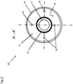
- a sealing element 16 is provided between the first fastener or flange 11 and the second fastener or flange 13. As depicted in Fig. 2 , sealing element 16 is positioned between an inner piping 17 and the welding area 15 and completely surrounds and seals the inner piping 17.
- the sealing element 16 is compressed between the flanges 11, 13.
- each locating pin 18 is provided in one of the flanges 11, 13 and is in mutual engagement with a recess or a hole provided in the opposite flange.
- the locating pins or locator pins 18 provide an exact positioning of the flanges 11, 13 relative to each other when they are connected to each other.
- the fasteners or flanges 11, 13 are formed as discs in this embodiment. Both flanges 11, 13 have a flat connection surface 19 for mutual connection. In other embodiments, the fasteners 11, 13 may have another shape providing a common connection surface where they are contacting each other when they are being connected.
- the sealing element or sealing 16 is annular and extends on connection surface 19 around the inner piping 17 in order to seal it from the outside.
- first fastener or flange 11 which is connected to first fluid line or pipe 12
- second fastener or flange 13 which is connected to second fluid line or pipe 14 is provided.
- the flanges 11, 12 are positioned via locating pins 18 so that they face each other.
- Sealing element 16 is positioned between the first flange 11 and the second flange 13 so that it encloses inner piping 17 within the fasteners when they are connected.
- sealing element 16 it is possible to position sealing element 16 first, e.g. on one of the fasteners 11, 12, and then both flanges 11, 13 are positioned via the locating pins 18. As an alternative, the sealing element can be positioned between the flanges 11, 12 after they are positioned via the locating pins 18.
- first and the second fasteners or flanges 11, 13 are pressed against each other so that the sealing element 16 is pressed between the flanges 11, 13 and seals the enclosed inner piping 17.
- a mounting tool 21 forming an installation device is used, which clamps both flanges 11, 13 together. Mounting tool 21 will be explained in more detail further below.
- first flange 11 is welded to the second flange 13, whereby a continuous weld connection is created, which completely surrounds the sealing element 16 and the enclosed inner piping 17.
- the mounting tool 21 comprises a first clamp unit 22 configured to hold the first pipe 12. It further comprises a second clamp unit 23 configured to press flange 13 provided at the end of pipe 14 against flange 11 provided at the end of pipe 12.
- the first clamp unit 22 comprises two clamp elements formed as half pipes 24 for grabbing the first pipe 12. Thus, it forms a pipe clamp configured to hold first pipe 12 tight between the clamp elements or half pipes 24.
- the clamp or clamp unit 22 comprises two half pipes 24 which are bolted together.
- the mounting tool 21 has several arms 25, 26 to fix both ends of the parts to be connected, in particular for initial spot welding. For clarity reason, only two arms are shown in the figures, however, there may be a higher number of arms 25, 26. Ba the arms 25, 26 the flanges are pressed together symmetrically and evenly. The arms 25, 26 are provided by clamps 22, 23 to surround the two flanges 11, 13 and to press them together, so that the seal 16 gets effective in protecting the inner piping 17 from the area to be welded 15. There are preferably several arms 25, 26 which are equally distributed over the flanges 11, 13. Advantageously, the arms 25, 26 are removable
- the flanges 11, 13 are spot welded, the clamps 22, 23 are removed and then the flanges 11, 13 are completely welded. Swarf falling down from the welding process is falling between the welding area 15 and the seal 16. It will stay there encapsulated throughout the lifetime of the connection 10 and thus it will not contaminate the inner piping 17.
- the seal 16 is positioned far enough from the welding area 15 in order to be protected against the welding heat.
- the process is done in the opposite way.
- the weld joint 15 is cut open e.g. with a milling machine or a similar tool while holding the fasteners or flanges 11, 13 together.
- a gap is created between the fasteners 11, 13 at or near the outer edge of the weld connection while the sealing element 16 is still contacting both fasteners 11, 13 and enclosing the inner piping 17.
- the space or gap between the two flanges 11, 13 is flushed and cleaned from swarf before removing the clamping tool 21.
- the gap is e.g. blown out or rinsed out e.g. by pressurized air or by water.
- the embodiment described above shall be understood as just one example.
- the invention can be realized by other possible forms of constructions which comprise an inner seal and an outer welded connection.
- the clamps shown in the figures may be differently designed.
- the locator pins or elements may be differently positioned, e.g. closer to the center of the flanges or at other locations. In other preferred embodiments, the locator pins are e.g. designed as tongues and grooves.
- the invention is designed for connecting cryogenic (liquid) hydrogen piping, in particular in aviation. However, it can also be applied in other applications, where a welded connection is preferred and cleanliness of the inner piping is important.
Landscapes
- Engineering & Computer Science (AREA)
- Mechanical Engineering (AREA)
- General Engineering & Computer Science (AREA)
- Physics & Mathematics (AREA)
- Optics & Photonics (AREA)
- Branch Pipes, Bends, And The Like (AREA)
Abstract
Description
- The invention relates to a method of making a weld connection for a fluid line, as well as to a method of disconnecting a welded fluid line connection. Further, the invention relates to a welded fluid line connection. Still further, the invention relates to a mounting tool for connecting fluid lines.
- The invention is in particular applicable for cryogenic or liquid hydrogen piping in aviation, where liquid hydrogen (LH2) pipes are connected to each other or to a specific equipment which e.g. uses the hydrogen.
- The invention can also be applied in all other applications where a welded connection is preferred and cleanliness of the piping is important.
- Couplings between LH2 pipes or equipment parts which use LH2 are for example bolted with seals. However, hydrogen may diffuse through the seals. Therefore, a weld connection is usually preferred for liquid hydrogen pipe connections or couplings, which prevents the hydrogen from escaping from the coupling.
- However, the welding and cutting processes result in swarf and debris which may penetrate into the piping.
- It is the object of the invention to provide a weld connection for a fluid line and a method of making same, which prevents hydrogen and other substances from escaping, and which prevents a pollution of the inner piping due to the welding and/or cutting process. Further, a pollution of the inner piping by debris or similar materials shall be prevented when the interconnected pipes or parts are disconnected e.g. by a cutting process. In addition, a tool shall be provided which enables or facilitates the creation of such a weld connection.
- According to a first aspect, the invention provides a method of making a weld connection for a fluid line, comprising the steps: providing a first fastener connected to a first fluid line and a second fastener connected to a second fluid line; providing a sealing element between the first fastener and the second fastener so that it encloses an inner piping provided within the fasteners when they are connected; pressing the first and the second fastener against each other so that the sealing element is pressed between the fasteners and seals the enclosed inner piping; and welding the first fastener to the second fastener, whereby a continuous weld connection is created which completely surrounds the sealing element and the enclosed inner piping.
- In particular, the fluid lines or only one of them may be configured as a pipe or line configured for the transport of liquid hydrogen. It may also be configured as an equipment part which shall be connected to the liquid hydrogen line or pipe.
- Preferably, the fasters or at least one of the fasteners may be configured as a flange.
- As an alternative, the fasteners are configured as portions of the lines or pipes which are formed to be connected by inserting them into each other and welding both together. In this case, the fasteners are e.g. end portions of the lines or pipes.
- Preferably, the fasteners are positioned relative to each other via locating elements or locator elements provided between the fasteners, and clamped together before they are welded to each other.
- Preferably the fasteners are positioned so that they face each other before they are connected.
- The sealing element may either be positioned, e.g. on one of the fasteners, before they are positioned via the locating elements, or it may be positioned between the fasteners after the fasteners are positioned via the locating elements.
- The locating elements are preferably configured as pins or locating pins.
- Preferably, at least one of the fluid lines is grabbed by a mounting tool.
- Preferably, at least one of the fasteners is surrounded by the mounting tool which presses the fasteners against each other.
- According to a second aspect, the invention provides a method of disconnecting a welded fluid line connection, wherein the fluid line connection comprises at least two fasteners welded together and wherein each fastener is connected to a fluid line, a sealing element positioned between the fasteners so that it encloses and seals an inner piping provided within the interconnected fasteners, and a weld joint completely surrounding the sealing element, the method comprising the steps:
- (a) opening the weld joint while holding the fasteners together;
- (b) creating a gap between the fasteners while the sealing element is still contacting both fasteners and enclosing the inner hydrogen piping;
- (c) blowing out and/or rinsing out the gap;
- (d) thereafter separating the fasteners from each other.
- According to a third aspect, the invention provides a welded fluid line connection, comprising: a first fastener connected to a first fluid line and a second fastener connected to a second fluid line, wherein the fasteners are welded together at a welding area which forms a continuous weld joint which completely surrounds and seals an inner piping of the interconnected fasteners, a sealing element provided between the first and second fastener, wherein the sealing element is positioned between the inner piping and the welding area and completely surrounds and seals the inner piping.
- Preferably, the sealing element is compressed between the fasteners.
- Preferably, at least one of the fluid lines is configured as a pipe.
- Preferably, at least one of the fluid lines is configured as an equipment unit of a fluid line installation.
- Preferably, the fasteners are configured as flanges.
- Preferably, the fluid lines are configured to transport hydrogen, in particular liquid hydrogen.
- Preferably, locating elements provided between the fasteners are designed to exactly position the fasteners relative to each other.
- In particular, the locating elements may be formed as pins.
- According to a fourth aspect, the invention provides a mounting tool for connecting fluid lines, wherein a first fluid line and a second fluid line are each comprising a fastener provided at an end of the respective fluid line, the mounting tool comprising: a first clamp unit configured to hold the first fluid line and/or the fastener provided at its end; a second clamp unit configured to press the fastener of the second fluid line against the fastener of the first fluid line; wherein the first and second clamp units are movable against each other to press the fasteners together and comprise (a) a pipe clamp configured to hold one of the fluid lines, and/or (b) one or more arms configured to surround at least one of the fasteners in order to press it against the other fastener.
- Preferably, the arms are removable.
- Preferably, the arms are equally distributed over the fastener when it is pressed against the other fastener.
- Preferably, the fasteners are configured as flanges.
- Preferably, at least one of the fluid lines is configured as a pipe, in particular as a pipe for the transport of liquid hydrogen.
- The weld connection according to the invention is in particular applicable for liquid hydrogen pipes. It is leak tight due to the continuous surrounding welding, and by the inner sealing it protects the pipe inside against contamination from the welding and/or cutting process. The inner seal also acts as a redundant seal or sealing method to achieve dissimilar double barrier against leakage.
- In particular, the invention provides a welded piping connection protecting the inner pipes with a seal from the welding area in order to prevent pollution of the inner piping due to the welding and/or a cutting. In particular, swarf or debris generated by welding and/or cutting is prevented from entering into the piping.
- Characteristics and advantages described in relation to the method of making a weld connection are also related to the method of disconnecting a welded fluid line connection and to the welded fluid line connection. The same applies vice versa, and it applies also for the mounting tool.
- In the following, a particularly preferred embodiment of the invention showing further characteristics and advantages is described in detail with reference to the figures, in which:
- Fig. 1
- shows welded fluid line connection according to a preferred embodiment of the invention as a side view; and
- Fig. 2
- shows the fluid line connection depicted in
Fig. 1 as a sectional view along dotted line A - A' inFig. 1 - In the figures, similar or identical elements and features are designated by the same reference numbers.
-
Figs. 1 and2 show a weldedfluid line connection 10 which is designed for the transport of liquid hydrogen. Theconnection 10 forms a coupling or LH2 coupling. It comprises afirst fastener 11 which is connected to afirst fluid line 12, and asecond fastener 13 which is connected to asecond fluid line 14. In this preferred embodiment, thefasteners fluid lines - The fasteners or
flanges welding area 15 which forms a continuous weld joint. Thewelding area 15 completely surrounds and seals aninner piping 17 of the interconnectedflanges - A
sealing element 16 is provided between the first fastener orflange 11 and the second fastener orflange 13. As depicted inFig. 2 ,sealing element 16 is positioned between aninner piping 17 and thewelding area 15 and completely surrounds and seals theinner piping 17. - The sealing
element 16 is compressed between theflanges - A number of locating elements formed as locating
pins 18 are extending between theflanges pin 18 is provided in one of theflanges flanges - A shown in
Fig. 2 , the fasteners orflanges flanges flat connection surface 19 for mutual connection. In other embodiments, thefasteners - The sealing element or sealing 16 is annular and extends on
connection surface 19 around theinner piping 17 in order to seal it from the outside. - In the following, also with reference to
figures 1 and2 , a preferred example of a method of making aweld connection 10 is described. In this example, theweld connection 10 as described above is created. - As a first step, first fastener or
flange 11 which is connected to first fluid line orpipe 12 is provided, and second fastener orflange 13 which is connected to second fluid line orpipe 14 is provided. - Then, the
flanges pins 18 so that they face each other. Sealingelement 16 is positioned between thefirst flange 11 and thesecond flange 13 so that it enclosesinner piping 17 within the fasteners when they are connected. - It is possible to position sealing
element 16 first, e.g. on one of thefasteners flanges flanges - Then, the first and the second fasteners or
flanges element 16 is pressed between theflanges inner piping 17. For this, a mountingtool 21 forming an installation device is used, which clamps bothflanges tool 21 will be explained in more detail further below. - Then, the
first flange 11 is welded to thesecond flange 13, whereby a continuous weld connection is created, which completely surrounds the sealingelement 16 and the enclosedinner piping 17. - The mounting
tool 21 comprises afirst clamp unit 22 configured to hold thefirst pipe 12. It further comprises asecond clamp unit 23 configured to pressflange 13 provided at the end ofpipe 14 againstflange 11 provided at the end ofpipe 12. - The
first clamp unit 22 comprises two clamp elements formed ashalf pipes 24 for grabbing thefirst pipe 12. Thus, it forms a pipe clamp configured to holdfirst pipe 12 tight between the clamp elements orhalf pipes 24. In the preferred embodiment, the clamp or clampunit 22 comprises twohalf pipes 24 which are bolted together. - The mounting
tool 21 hasseveral arms arms arms arms clamps flanges seal 16 gets effective in protecting theinner piping 17 from the area to be welded 15. There are preferablyseveral arms flanges arms - The first and
second clamp units flanges - After that, the
flanges clamps flanges welding area 15 and theseal 16. It will stay there encapsulated throughout the lifetime of theconnection 10 and thus it will not contaminate theinner piping 17. Theseal 16 is positioned far enough from thewelding area 15 in order to be protected against the welding heat. - When reopening the
weld connection 10, the process is done in the opposite way. First, the weld joint 15 is cut open e.g. with a milling machine or a similar tool while holding the fasteners orflanges fasteners element 16 is still contacting bothfasteners inner piping 17. - Then, the space or gap between the two
flanges clamping tool 21. The gap is e.g. blown out or rinsed out e.g. by pressurized air or by water. - Finally, the two
pipes fasteners seal 16 may be removed. - The embodiment described above shall be understood as just one example. The invention can be realized by other possible forms of constructions which comprise an inner seal and an outer welded connection. Also the clamps shown in the figures may be differently designed. The locator pins or elements may be differently positioned, e.g. closer to the center of the flanges or at other locations. In other preferred embodiments, the locator pins are e.g. designed as tongues and grooves.
- The invention is designed for connecting cryogenic (liquid) hydrogen piping, in particular in aviation. However, it can also be applied in other applications, where a welded connection is preferred and cleanliness of the inner piping is important.
-
- 10
- fluid line connection / weld connection
- 11
- first fastener or flange
- 12
- first fluid line or pipe
- 13
- second fastener or flange
- 14
- second fluid line or pipe
- 15
- welding area /weld joint
- 16
- sealing element / seal
- 17
- inner piping
- 18
- as locating elements or pins
- 19
- connection surface
- 21
- mounting tool
- 22
- first clamp unit or clamp
- 23
- second clamp unit or clamp
- 24
- clamp elements / half pipes
- 25, 26
- arms
Claims (10)
- Method of making a weld connection for a fluid line, comprising the steps:(a) Providing a first fastener (11) connected to a first fluid line (12) and a second fastener (13) connected to a second fluid line (14);(b) providing a sealing element (16) between the first fastener (11) and the first fastener (13) so that it encloses an inner piping (17) provided within the fasteners (11, 13) when they are connected;(c) pressing the first fastener (11) and the second fastener (13) against each other so that the sealing element (16) is pressed between the fasteners (11, 13) and seals the enclosed inner piping (17); and(d) welding the first fastener (11) to the second fastener (13), whereby a continuous weld connection (10) is created which completely surrounds the sealing element (16) and the enclosed inner piping (17).
- Method according to claim 1, characterized in that the fasteners (11, 13) are positioned via locating elements (18) provided between the fasteners (11, 13) and clamped together before they are welded to each other.
- Method according to claim 1 or 2, characterized in that at least one of the fluid lines (12, 14) is grabbed by a mounting tool (21), and at least one of the fasteners (11, 13) is surrounded a by the mounting tool (21) which presses the fasteners (11, 13) against each other.
- Method of disconnecting a welded fluid line connection, wherein the fluid line connection comprisesat least two fasteners (11, 13) welded together, wherein each fastener (11, 13) is connected to a fluid line (12, 14), a sealing element (16) positioned between the fasteners (11, 13) so that it encloses and seals an inner piping (17) provided within the interconnected fasteners (11, 13), and a weld joint (10) completely surrounding the sealing element (16),the method comprising the steps:(a) opening the weld joint (10) while holding the fasteners (11, 13) together;(b) creating a gap between the fasteners (11, 13) while the sealing element (16) is still contacting both fasteners (11, 13) and enclosing the inner piping (17);(c) blowing out and/or rinsing out the gap;(d) thereafter separating the fasteners (11, 13) from each other.
- Welded fluid line connection, comprising:a first fastener (11) connected to a first fluid line (12) and a first fastener (13) connected to a second fluid line (14),wherein the fasteners (11, 13) are welded together at a welding area (15) which forms a continuous weld joint (10) which completely surrounds and seals an inner piping (17) of the interconnected fasteners (11, 13),a sealing element (16) provided between the first fastener (11) and the second fastener (13), wherein the sealing element (16) is positioned between the inner piping (17) and the welding area (15) and completely surrounds and seals the inner piping (17).
- Welded fluid line connection according to claim 5, characterized in that the sealing element (16) is compressed between the fasteners (11, 13).
- Welded fluid line connection according to claim 5 or 6, characterized in that7.1. at least one of the fluid lines (12, 14) is configured as a pipe; and/or7.2. at least one of the fluid lines (12, 14) is configured as an equipment unit of a fluid line installation; and/or7.3. the fasteners (11, 13) are configured as flanges; and/or7.4. the fluid lines (12, 14) are configured to transport liquid hydrogen.
- Welded fluid line connection according to one of claims 5 to 7, characterized by locating elements (18) provided between the fasteners (11, 13) designed to exactly position the fasteners (11, 13) relative to each other.
- Mounting tool for connecting fluid lines, wherein a first fluid line (12) and a second fluid line (14) are each comprising a fastener (11, 13) provided at an end of the respective fluid line (12, 14), the mounting tool (10) comprising:a first clamp unit (22) configured to hold the first fluid line (12) and/or the fastener (11) provided at its end;a second clamp unit (23) configured to press the fastener (13) of the second fluid line (14) against the fastener (11) of the first fluid line (12);wherein the first and second clamp units (22, 23) are movable against each other to press the fasteners (11, 13) together and comprise(a) a pipe clamp (24) configured to hold one of the fluid lines (12), and/or(b) one or more arms (25, 26) configured to surround one of the fasteners (11, 13) in order to press it against the other fastener (11, 13).
- Mounting tool according to claim 9, characterized in that10.1. the arms (25, 26) are removable; and/or10.2. the arms (25, 26) are equally distributed over the fastener (13) when it is pressed against the other fastener (11); and/or10.3. the fasteners (11, 13) are configured as flanges; and/or10.4. at least one of the fluid lines (12, 14) is configured as a pipe.
Priority Applications (3)
| Application Number | Priority Date | Filing Date | Title |
|---|---|---|---|
| EP23166057.2A EP4438933A1 (en) | 2023-03-31 | 2023-03-31 | Method of making a weld connection for a fluid line, method of disconnecting it, welded fluid line connection, and mounting tool |
| CN202410367613.2A CN118729066A (en) | 2023-03-31 | 2024-03-28 | Method for manufacturing a welded connection for a fluid pipeline, method for disconnecting a welded connection, welded fluid pipeline connection, and installation tool |
| US18/620,092 US20240326180A1 (en) | 2023-03-31 | 2024-03-28 | Method of making a weld connection for a fluid line, method of disconnecting it, welded fluid line connection, and mounting tool |
Applications Claiming Priority (1)
| Application Number | Priority Date | Filing Date | Title |
|---|---|---|---|
| EP23166057.2A EP4438933A1 (en) | 2023-03-31 | 2023-03-31 | Method of making a weld connection for a fluid line, method of disconnecting it, welded fluid line connection, and mounting tool |
Publications (1)
| Publication Number | Publication Date |
|---|---|
| EP4438933A1 true EP4438933A1 (en) | 2024-10-02 |
Family
ID=85800681
Family Applications (1)
| Application Number | Title | Priority Date | Filing Date |
|---|---|---|---|
| EP23166057.2A Pending EP4438933A1 (en) | 2023-03-31 | 2023-03-31 | Method of making a weld connection for a fluid line, method of disconnecting it, welded fluid line connection, and mounting tool |
Country Status (3)
| Country | Link |
|---|---|
| US (1) | US20240326180A1 (en) |
| EP (1) | EP4438933A1 (en) |
| CN (1) | CN118729066A (en) |
Citations (5)
| Publication number | Priority date | Publication date | Assignee | Title |
|---|---|---|---|---|
| GB718267A (en) * | 1951-01-08 | 1954-11-10 | Harold Newby | Improvements in pipe joints |
| JPS5818180U (en) * | 1981-07-29 | 1983-02-04 | 株式会社日立製作所 | Flange fitting with bellows |
| CA2934317A1 (en) * | 2013-12-18 | 2015-06-25 | Isco Industries, Inc. | Assembly and method of coupling pipes |
| US9808893B2 (en) * | 2013-12-19 | 2017-11-07 | Walhonde Tools Inc. | Apparatus for aligning sections of pipe |
| CN114623295A (en) * | 2022-04-01 | 2022-06-14 | 宁波汇洲生态建设有限公司 | Connecting structure of water supply pipeline and construction method thereof |
Family Cites Families (57)
| Publication number | Priority date | Publication date | Assignee | Title |
|---|---|---|---|---|
| US1323383A (en) * | 1919-12-02 | wellman | ||
| US1926107A (en) * | 1932-03-17 | 1933-09-12 | Walworth Patents Inc | Sealing device |
| US3325191A (en) * | 1964-05-01 | 1967-06-13 | Gulf Oil Corp | Lined pipe joint and process of forming same |
| US3328053A (en) * | 1964-06-10 | 1967-06-27 | Chemetron Corp | Insulated pipe joint |
| US4000921A (en) * | 1975-07-21 | 1977-01-04 | Ronald Albert Daspit | Tubular clamping and sealing coupler |
| GB1499346A (en) * | 1975-10-02 | 1978-02-01 | Daspit R | Clamping and sealing coupling for pipelines |
| US4281859A (en) * | 1976-01-09 | 1981-08-04 | Le Carbone (Great Britain) Limited | Pipe joints |
| US4288105A (en) * | 1979-02-21 | 1981-09-08 | Resistoflex Corporation | Pipe union with both pre-load dependent and independent seals |
| US4320910A (en) * | 1980-06-05 | 1982-03-23 | The Dow Chemical Company | Protective shield for a pipe flange connection |
| US4728126A (en) * | 1986-08-04 | 1988-03-01 | Sundholm Goeran | Weld joint |
| US5123679A (en) * | 1991-03-01 | 1992-06-23 | Westinghouse Electric Corp. | Connection together of pipes by breakable welded joint |
| GB2257385B (en) * | 1991-07-11 | 1994-11-02 | Rolls Royce Plc | Improvements in or relating to diffusion bonding |
| JPH05248542A (en) * | 1991-12-30 | 1993-09-24 | Japan Atom Energy Res Inst | Vacuum sealing structure using metal gasket, vacuum sealing method, metal gasket for vacuum sealing, and vacuum flange for metal gasket |
| GB2284872B (en) * | 1991-12-30 | 1996-08-28 | Japan Atomic Energy Res Inst | Vacuum flange |
| US5490680A (en) * | 1993-04-06 | 1996-02-13 | Parker-Hannifin Corporation | Captive O-ring face seal |
| DE19607898A1 (en) * | 1996-03-01 | 1997-09-04 | Ritz Reinert Gmbh | Flange connection for pipes, containers, apparatus or the like made of plastic |
| KR200403574Y1 (en) * | 2005-09-30 | 2005-12-09 | 주식회사 아세아유니온 | Jointing structure of flange for piping |
| KR20100047414A (en) * | 2008-10-29 | 2010-05-10 | 김인배 | Vibration isolator at pipe connection |
| US9611960B2 (en) * | 2013-02-28 | 2017-04-04 | Spears Manufacturing Co. | Cut-in fitting for connecting pipe |
| CN104295827B (en) * | 2013-07-17 | 2016-12-28 | 五冶集团上海有限公司 | Heavy caliber gas pipeline anti-leak packing ring and using method |
| CN103672240A (en) * | 2013-12-05 | 2014-03-26 | 天津泉达农作物种植有限公司 | Novel pipeline connecting pressure-resisting flange and application |
| CN105042259B (en) * | 2015-07-28 | 2017-03-08 | 中船动力有限公司 | Double-wall expansion joint and installation method |
| NO342547B1 (en) * | 2015-12-08 | 2018-06-11 | Vetco Gray Scandinavia As | Tubular joint |
| KR101818324B1 (en) * | 2016-03-04 | 2018-01-15 | 주식회사 엠엠피 | Electro-fusion apparatus for transfer tube of fluid including chemical material |
| CN105782604B (en) * | 2016-04-14 | 2018-05-29 | 利辛县风雅颂机电科技有限公司 | A kind of vacuum protection formula flange connector |
| CN105715889B (en) * | 2016-04-14 | 2018-08-28 | 上海盛剑通风管道有限公司 | A kind of antiseep flange connector |
| CN105805450B (en) * | 2016-04-14 | 2018-10-16 | 东台市远洋不锈钢制造有限公司 | A kind of magnetic conductance formula flange connector |
| CN107461556B (en) * | 2016-06-03 | 2024-05-03 | 开利公司 | Flange connection assembly, assembling and disassembling method thereof, pipeline connection device and cooler unit |
| KR101805117B1 (en) * | 2016-07-21 | 2017-12-05 | 주식회사 조흥밸브앤파이프 | Construction method for high pressure natural gas pipe line utilizing flanged pipes |
| CN106195492A (en) * | 2016-08-04 | 2016-12-07 | 段桂英 | A kind of high-pressure hose flanging joint and using method thereof |
| CN109114327A (en) * | 2017-06-22 | 2019-01-01 | 陕西星辰石油科技有限责任公司 | A kind of oil tube connection device |
| CN109282095A (en) * | 2018-08-17 | 2019-01-29 | 弗通流体科技(上海)有限公司 | Retaining ring flange pipe connection system |
| CN109282097A (en) * | 2018-08-17 | 2019-01-29 | 弗通流体科技(上海)有限公司 | It is flared flange pipe connection system |
| CN112145824B (en) * | 2019-06-28 | 2022-07-26 | 国家能源投资集团有限责任公司 | Pipe fitting joint sealing structure and joint protection method |
| DE102019122355A1 (en) * | 2019-08-20 | 2021-02-25 | KLINGER Kempchen GmbH | Flange connection with welding ring seal |
| CN110939811B (en) * | 2019-12-25 | 2024-03-12 | 优捷特清洁能源有限公司 | Vacuum low-temperature pipeline plane flange sealing structure and installation method thereof |
| CN111140698B (en) * | 2019-12-31 | 2024-07-26 | 北京凯盛建材工程有限公司 | Waterproof wall bushing structure with flexible dynamic seal assembly arranged on neutral surface and construction method |
| CN111365560A (en) * | 2020-03-04 | 2020-07-03 | 宣化钢铁集团有限责任公司 | Method for treating steam leakage of steam pipeline flange without stopping steam |
| KR102220519B1 (en) * | 2020-05-08 | 2021-02-24 | 김경철 | Flange assembly for pipe duct connection |
| CN111442145A (en) * | 2020-05-20 | 2020-07-24 | 张家港华日法兰有限公司 | High-pressure flange structure and machining method thereof |
| DE202020103581U1 (en) * | 2020-06-22 | 2021-06-24 | Hollnack & Steinbach GmbH & Co. KG | Flange connection arrangement for a pipeline |
| KR102424582B1 (en) * | 2020-07-09 | 2022-07-26 | 문재화 | Flanged pipe for fluid of high pressure |
| CN111981217A (en) * | 2020-09-01 | 2020-11-24 | 赣州市闻誉科技有限公司 | Anti-loosening structure for bolt on water pump pipeline |
| CN112094166B (en) * | 2020-09-14 | 2023-12-08 | 江苏博颂能源科技有限公司 | An anti-leakage mechanism when assembling waste pot modules for ethylene cracking furnaces |
| CN112113048A (en) * | 2020-09-15 | 2020-12-22 | 靖江市富源船舶配件有限公司 | Flange convenient for butt joint of ship pipelines |
| CN111981216B (en) * | 2020-09-18 | 2021-12-28 | 山西天宝集团有限公司 | Pressure gas pipeline flange |
| KR102454119B1 (en) * | 2020-11-18 | 2022-10-14 | (주)브이월드코리아 | Flange pipe for fluid of high pressure of which leaking test is easy at site |
| CN112555537A (en) * | 2020-12-24 | 2021-03-26 | 玫德集团有限公司 | Low pressure pipeline hubbed flange self sealss attach fitting |
| CN113007186A (en) * | 2021-02-25 | 2021-06-22 | 江苏荣光五金科技有限公司 | Flange plate with adjustable internal structure |
| CN112963636A (en) * | 2021-02-25 | 2021-06-15 | 江苏荣光五金科技有限公司 | Stainless steel flange with external adjusting module |
| CN113217724A (en) * | 2021-06-09 | 2021-08-06 | 惠州市承业建筑工程有限公司 | Pipeline connecting structure for municipal water supply and drainage |
| CN113833918A (en) * | 2021-08-27 | 2021-12-24 | 北京工业大学 | Lining structure of high-pressure water injection composite pipeline in oil field |
| CN113983252B (en) * | 2021-10-29 | 2022-12-13 | 临海伟星新型建材有限公司 | High-voltage connecting structure for steel wire mesh reinforced composite pipe and manufacturing method thereof |
| CN114738563B (en) * | 2022-04-24 | 2024-06-14 | 中国海洋石油集团有限公司 | Insulation method and device for dissimilar metal submarine pipeline |
| CN114952069B (en) * | 2022-05-30 | 2024-04-02 | 攀钢集团西昌钢钒有限公司 | Pipeline welding joint structure and welding method |
| CN116518206A (en) * | 2023-04-27 | 2023-08-01 | 大连洁净能源集团有限公司 | Regional heating pipeline heat-insulating layer partition pipe fitting and installation method thereof |
| CN116464846B (en) * | 2023-05-19 | 2026-02-27 | 无锡市恒亿杰石化机械有限公司 | A high-strength impact-resistant weld neck flange for oil pipelines |
-
2023
- 2023-03-31 EP EP23166057.2A patent/EP4438933A1/en active Pending
-
2024
- 2024-03-28 CN CN202410367613.2A patent/CN118729066A/en active Pending
- 2024-03-28 US US18/620,092 patent/US20240326180A1/en active Pending
Patent Citations (5)
| Publication number | Priority date | Publication date | Assignee | Title |
|---|---|---|---|---|
| GB718267A (en) * | 1951-01-08 | 1954-11-10 | Harold Newby | Improvements in pipe joints |
| JPS5818180U (en) * | 1981-07-29 | 1983-02-04 | 株式会社日立製作所 | Flange fitting with bellows |
| CA2934317A1 (en) * | 2013-12-18 | 2015-06-25 | Isco Industries, Inc. | Assembly and method of coupling pipes |
| US9808893B2 (en) * | 2013-12-19 | 2017-11-07 | Walhonde Tools Inc. | Apparatus for aligning sections of pipe |
| CN114623295A (en) * | 2022-04-01 | 2022-06-14 | 宁波汇洲生态建设有限公司 | Connecting structure of water supply pipeline and construction method thereof |
Also Published As
| Publication number | Publication date |
|---|---|
| US20240326180A1 (en) | 2024-10-03 |
| CN118729066A (en) | 2024-10-01 |
Similar Documents
| Publication | Publication Date | Title |
|---|---|---|
| EP0047407B1 (en) | Sleeving method | |
| US7827853B2 (en) | Weld testing apparatus and method for nozzles | |
| EP0526675B1 (en) | Diameter-reducing member joint device | |
| US5163715A (en) | Lined pipe connection device and method | |
| EP1647753A1 (en) | Pipe joint | |
| US4581801A (en) | Sleeving method | |
| US20240326180A1 (en) | Method of making a weld connection for a fluid line, method of disconnecting it, welded fluid line connection, and mounting tool | |
| US20230417356A1 (en) | Bolted and welded clamp-type repair with recessed bolts | |
| EP0056327A2 (en) | A pipe connector | |
| US5321233A (en) | Electrofusion fitting and sealing method for distribution line | |
| US4950000A (en) | Flanged pipeline connections | |
| GB2047834A (en) | Coupling joint and method for plastic lined pipe | |
| US5513794A (en) | Method for fixing stopper ring to pipe spigot | |
| JPS61160690A (en) | High-pressure pipe joint | |
| EP0302618A1 (en) | Connecting device | |
| EP4425024A1 (en) | Systems and methods for forming a joint between a pipe and a hose | |
| JP2655392B2 (en) | Telescopic flexible pipe joint | |
| KR102060562B1 (en) | structure for connecting plastic pipes for treating wastewater of semiconductor manufacturing equipment | |
| JPH10166184A (en) | Cooling pipe assembly jig for superconducting coil and pipe welding jig | |
| KR200242167Y1 (en) | pipe clamp | |
| JP2009085378A (en) | Piping repair tool | |
| JP2002327881A (en) | Coupling for fluid piping | |
| JP2002071068A (en) | Connection method and connection structure | |
| JPS60196265A (en) | Welding method of pipe | |
| JPS58501087A (en) | High temperature valve bonnet |
Legal Events
| Date | Code | Title | Description |
|---|---|---|---|
| PUAI | Public reference made under article 153(3) epc to a published international application that has entered the european phase |
Free format text: ORIGINAL CODE: 0009012 |
|
| STAA | Information on the status of an ep patent application or granted ep patent |
Free format text: STATUS: THE APPLICATION HAS BEEN PUBLISHED |
|
| AK | Designated contracting states |
Kind code of ref document: A1 Designated state(s): AL AT BE BG CH CY CZ DE DK EE ES FI FR GB GR HR HU IE IS IT LI LT LU LV MC ME MK MT NL NO PL PT RO RS SE SI SK SM TR |
|
| STAA | Information on the status of an ep patent application or granted ep patent |
Free format text: STATUS: REQUEST FOR EXAMINATION WAS MADE |
|
| 17P | Request for examination filed |
Effective date: 20250324 |
|
| STAA | Information on the status of an ep patent application or granted ep patent |
Free format text: STATUS: EXAMINATION IS IN PROGRESS |
|
| 17Q | First examination report despatched |
Effective date: 20251121 |