EP4438902A1 - Rotor assembly of electronic water pump and electronic water pump - Google Patents
Rotor assembly of electronic water pump and electronic water pump Download PDFInfo
- Publication number
- EP4438902A1 EP4438902A1 EP22895004.4A EP22895004A EP4438902A1 EP 4438902 A1 EP4438902 A1 EP 4438902A1 EP 22895004 A EP22895004 A EP 22895004A EP 4438902 A1 EP4438902 A1 EP 4438902A1
- Authority
- EP
- European Patent Office
- Prior art keywords
- bearing
- assembly
- rotor assembly
- cover plate
- bearing assembly
- Prior art date
- Legal status (The legal status is an assumption and is not a legal conclusion. Google has not performed a legal analysis and makes no representation as to the accuracy of the status listed.)
- Withdrawn
Links
Images



Classifications
-
- F—MECHANICAL ENGINEERING; LIGHTING; HEATING; WEAPONS; BLASTING
- F04—POSITIVE - DISPLACEMENT MACHINES FOR LIQUIDS; PUMPS FOR LIQUIDS OR ELASTIC FLUIDS
- F04D—NON-POSITIVE-DISPLACEMENT PUMPS
- F04D29/00—Details, component parts, or accessories
- F04D29/04—Shafts or bearings, or assemblies thereof
- F04D29/046—Bearings
-
- F—MECHANICAL ENGINEERING; LIGHTING; HEATING; WEAPONS; BLASTING
- F04—POSITIVE - DISPLACEMENT MACHINES FOR LIQUIDS; PUMPS FOR LIQUIDS OR ELASTIC FLUIDS
- F04D—NON-POSITIVE-DISPLACEMENT PUMPS
- F04D13/00—Pumping installations or systems
- F04D13/02—Units comprising pumps and their driving means
- F04D13/06—Units comprising pumps and their driving means the pump being electrically driven
-
- F—MECHANICAL ENGINEERING; LIGHTING; HEATING; WEAPONS; BLASTING
- F04—POSITIVE - DISPLACEMENT MACHINES FOR LIQUIDS; PUMPS FOR LIQUIDS OR ELASTIC FLUIDS
- F04D—NON-POSITIVE-DISPLACEMENT PUMPS
- F04D13/00—Pumping installations or systems
- F04D13/02—Units comprising pumps and their driving means
- F04D13/06—Units comprising pumps and their driving means the pump being electrically driven
- F04D13/0606—Canned motor pumps
- F04D13/0633—Details of the bearings
-
- F—MECHANICAL ENGINEERING; LIGHTING; HEATING; WEAPONS; BLASTING
- F04—POSITIVE - DISPLACEMENT MACHINES FOR LIQUIDS; PUMPS FOR LIQUIDS OR ELASTIC FLUIDS
- F04D—NON-POSITIVE-DISPLACEMENT PUMPS
- F04D29/00—Details, component parts, or accessories
-
- F—MECHANICAL ENGINEERING; LIGHTING; HEATING; WEAPONS; BLASTING
- F04—POSITIVE - DISPLACEMENT MACHINES FOR LIQUIDS; PUMPS FOR LIQUIDS OR ELASTIC FLUIDS
- F04D—NON-POSITIVE-DISPLACEMENT PUMPS
- F04D29/00—Details, component parts, or accessories
- F04D29/02—Selection of particular materials
- F04D29/026—Selection of particular materials especially adapted for liquid pumps
-
- F—MECHANICAL ENGINEERING; LIGHTING; HEATING; WEAPONS; BLASTING
- F04—POSITIVE - DISPLACEMENT MACHINES FOR LIQUIDS; PUMPS FOR LIQUIDS OR ELASTIC FLUIDS
- F04D—NON-POSITIVE-DISPLACEMENT PUMPS
- F04D29/00—Details, component parts, or accessories
- F04D29/04—Shafts or bearings, or assemblies thereof
- F04D29/043—Shafts
- F04D29/044—Arrangements for joining or assembling shafts
-
- F—MECHANICAL ENGINEERING; LIGHTING; HEATING; WEAPONS; BLASTING
- F04—POSITIVE - DISPLACEMENT MACHINES FOR LIQUIDS; PUMPS FOR LIQUIDS OR ELASTIC FLUIDS
- F04D—NON-POSITIVE-DISPLACEMENT PUMPS
- F04D29/00—Details, component parts, or accessories
- F04D29/04—Shafts or bearings, or assemblies thereof
- F04D29/046—Bearings
- F04D29/047—Bearings hydrostatic; hydrodynamic
- F04D29/0473—Bearings hydrostatic; hydrodynamic for radial pumps
-
- F—MECHANICAL ENGINEERING; LIGHTING; HEATING; WEAPONS; BLASTING
- F04—POSITIVE - DISPLACEMENT MACHINES FOR LIQUIDS; PUMPS FOR LIQUIDS OR ELASTIC FLUIDS
- F04D—NON-POSITIVE-DISPLACEMENT PUMPS
- F04D29/00—Details, component parts, or accessories
- F04D29/18—Rotors
- F04D29/22—Rotors specially for centrifugal pumps
- F04D29/24—Vanes
-
- F—MECHANICAL ENGINEERING; LIGHTING; HEATING; WEAPONS; BLASTING
- F04—POSITIVE - DISPLACEMENT MACHINES FOR LIQUIDS; PUMPS FOR LIQUIDS OR ELASTIC FLUIDS
- F04D—NON-POSITIVE-DISPLACEMENT PUMPS
- F04D29/00—Details, component parts, or accessories
- F04D29/40—Casings; Connections of working fluid
- F04D29/42—Casings; Connections of working fluid for radial or helico-centrifugal pumps
-
- F—MECHANICAL ENGINEERING; LIGHTING; HEATING; WEAPONS; BLASTING
- F04—POSITIVE - DISPLACEMENT MACHINES FOR LIQUIDS; PUMPS FOR LIQUIDS OR ELASTIC FLUIDS
- F04D—NON-POSITIVE-DISPLACEMENT PUMPS
- F04D29/00—Details, component parts, or accessories
- F04D29/60—Mounting; Assembling; Disassembling
- F04D29/62—Mounting; Assembling; Disassembling of radial or helico-centrifugal pumps
-
- F—MECHANICAL ENGINEERING; LIGHTING; HEATING; WEAPONS; BLASTING
- F04—POSITIVE - DISPLACEMENT MACHINES FOR LIQUIDS; PUMPS FOR LIQUIDS OR ELASTIC FLUIDS
- F04D—NON-POSITIVE-DISPLACEMENT PUMPS
- F04D29/00—Details, component parts, or accessories
- F04D29/60—Mounting; Assembling; Disassembling
- F04D29/62—Mounting; Assembling; Disassembling of radial or helico-centrifugal pumps
- F04D29/628—Mounting; Assembling; Disassembling of radial or helico-centrifugal pumps especially adapted for liquid pumps
-
- F—MECHANICAL ENGINEERING; LIGHTING; HEATING; WEAPONS; BLASTING
- F05—INDEXING SCHEMES RELATING TO ENGINES OR PUMPS IN VARIOUS SUBCLASSES OF CLASSES F01-F04
- F05D—INDEXING SCHEME FOR ASPECTS RELATING TO NON-POSITIVE-DISPLACEMENT MACHINES OR ENGINES, GAS-TURBINES OR JET-PROPULSION PLANTS
- F05D2240/00—Components
- F05D2240/50—Bearings
Definitions
- the rotor assembly is the core component of the electronic water pump.
- the rotor assembly When the electronic water pump is in operation, the rotor assembly is energized and converts its own mechanical energy into the kinetic energy of the fluid.
- the quality of the rotor assembly seriously affects the efficiency of the electronic water pump. For example, if the dynamic balance accuracy of the rotor assembly is poor, it will cause vibration of the electronic water pump, reduce the service life of the electronic water pump, and cause greater noise and environmental pollution.
- a rotor assembly of an electronic water pump including:
- the bearing assembly includes a shaft sleeve, and the impeller seat has a bushing extending along the axial direction of the shaft sleeve and fitting with a hole wall of the first central through hole.
- a material of the impeller seat includes polyphenylene sulfide.
- the bearing assembly includes a shaft sleeve and a bearing
- the bearing is a graphite bearing.
- one of an outer wall of the bearing and an inner wall of the shaft sleeve has a groove, and the other has a protrusion limited in the groove.
- At least one of an outer wall of the bearing and an outer wall of the shaft sleeve has the first limiting part.
- a side wall of the end of the bearing assembly has a plurality of first limiting parts in a circumferential direction
- the impeller seat has an embedded groove accommodating a first end of the bearing assembly
- a groove wall of the embedded groove has a plurality of second limiting parts in the circumferential direction
- the plurality of second limiting parts are respectively limited within the plurality of the first limiting parts.
- the magnetic ring assembly includes an iron core assembly, a first cover plate, a second cover plate and a sleeve;
- an electronic water pump including a housing and the rotor assembly according to the above aspect; the housing has an inner cavity and a rotation shaft located in the inner cavity, and the rotor assembly is accommodated in the inner cavity and is rotatably sleeved on the rotation shaft.
- the coaxiality between the magnetic ring assembly and the bearing assembly is ensured by the interference-fit between the magnetic ring assembly and the bearing assembly, and then the magnetic ring assembly and the bearing assembly which are interference-fitted are connected to the impeller seat. Therefore, in the embodiments of the present disclosure, the number of insert injection molding processes is reduced when manufacturing the rotor assembly, thereby ensuring the dynamic balancing accuracy of the rotor assembly, avoiding vibration of the electronic water pump with the rotor assembly during operation, prolonging the service life of the electronic water pump, and at the same time avoiding the generation of noise that causes pollution to the environment.
- the impeller seat 3 wraps the end of the bearing assembly 1, and the impeller seat 3 has a second limiting part 31 in limiting fit with the first limiting part 12 for limiting purpose.
- the impeller cover 4 is fixedly connected to a side of the impeller seat 3 away from the bearing assembly 1.
- the coaxiality between the magnetic ring assembly 2 and the bearing assembly 1 is ensured through the interference-fit between the magnetic ring assembly 2 and the bearing assembly 1, and then the magnetic ring assembly 2 and the bearing assembly 1 which are interference-fitted are connected to the impeller seat 3. Therefore, in the embodiment of the present disclosure, the number of insert injection molding processes can be reduced when the rotor assembly is produced, thereby ensuring the dynamic balance accuracy of the rotor assembly, avoiding vibration of the electronic water pump with the rotor assembly during operation, and extending the service life of the electronic water pump while avoiding noise pollution to the environment.
- the relative rotation between the bearing assembly 1 and the impeller seat 3 can be limited by the cooperation of the first limiting part 12 and the second limiting part 31, thereby avoiding the phenomenon of slipping between the bearing assembly 1 and the impeller seat 3, and ensuring the efficiency of the rotor assembly.
- the first limiting part 12 is a limiting groove
- the second limiting part 31 is a limiting block; or, the first limiting part 12 is a limiting block, and the second limiting part 31 is a limiting groove, as long as a limit fit of the first limiting part 12 and the second limiting part 31 can be realized, and the embodiment of the present disclosure is not limited to this.
- the first end of the bearing assembly 1 extends out of the magnetic ring assembly 2, and the second end of the bearing assembly 1 extends out of the magnetic ring assembly 2 or is flush with the end surface of the magnetic ring assembly 2.
- the impeller cover 4 and the impeller seat 3 are welded and fixed. Specifically, the impeller cover 4 and the impeller seat 3 are fixed by ultrasonic welding. Of course, other connection methods are also possible, as long as the fixed connection between the impeller cover and the impeller seat can be achieved, and the embodiment of the present disclosure is not limited to this.
- the magnetic ring assembly 2 mainly includes an iron core assembly 21.
- the iron core assembly 21 has a second central through hole.
- the iron core assembly 21 is sleeved on the bearing assembly 1 based on the second central through hole.
- the iron core assembly 21 is interference-fitted with the bearing assembly 1 to ensure the coaxiality between the iron core assembly 21 and the bearing assembly 1.
- the iron core assembly 21 includes the above-mentioned iron core and magnetic steel.
- the iron core and the magnetic steel can be produced in advance through an one-piece molding process to ensure the coaxiality of the iron core and the magnetic steel.
- the one-piece molding process of the iron core and the magnetic steel can refer to the related art.
- the iron core and the magnetic steel can also be obtained through other processes, as long as the coaxiality of the iron core and the magnetic field can be ensured, and the embodiment of the present disclosure is not limited to this.
- a sealing cavity for accommodating the iron core assembly 21 can be formed, so as to achieve the sealing protection of the iron core assembly 21.
- connection between the first cover plate 22 the bearing assembly 1, the connection between the second cover plate 23 and the bearing assembly 1, the connection between the first cover plate 22 and the sleeve 24, and the connection between the second cover plate 23 and the sleeve 24 can be welded. Specifically, laser welding can be used. Of course, other connection methods are also possible, as long as the sealing protection of the iron core assembly 21 can be achieved, and the embodiment of the present disclosure is not limited to this.
- the bearing assembly 1 includes a shaft sleeve 13.
- the shaft sleeve 13 has a first central through hole 11, and the end of the shaft sleeve 13 has a first limiting part 12.
- the shaft sleeve 13 is configured to be rotatably sleeved on the rotating shaft.
- the shaft sleeve 13 can be configured as an embedded part, and the impeller seat 3 is formed on the end of the shaft sleeve 13 through an insert injection molding process.
- the impeller seat 3 can also be obtained by pre-injection molding, and then the impeller seat 3 is connected to the end of the shaft sleeve 13 while ensuring the limiting fit of the first limiting part 12 and the second limiting part 31.
- a bushing 32 is also formed on the inner wall of the first central through hole 11. That is to say, the impeller seat 3 has a bushing 32 extending along the axial direction of the shaft sleeve 13 and fitting with the hole wall of the first central through hole 11. In this way, when the rotor assembly rotates, the bushing 32 is in direct contact with the rotating shaft and rotates relatively, thereby avoiding contact between the shaft sleeve 13 and the rotating shaft.
- the material of the impeller seat 3 includes PPS (Polyphenylene sulphide).
- the bearing assembly 1 includes a shaft sleeve 13 and a bearing 14.
- the bearing 14 has a first central through hole 11.
- the shaft sleeve 13 is sleeved on the bearing 14 and interference-fitted with the bearing 14.
- the impeller seat 3 wraps at least one of the end of the bearing 14 and the end of the shaft sleeve 13.
- the interference-fit between the shaft sleeve 13 and the bearing 14 can ensure the coaxiality of the shaft sleeve 13 and the bearing 14 to ensure the dynamic balance accuracy of the rotor assembly.
- the bearing 14 is configured to be rotatable limited on the rotating shaft.
- the first end of the bearing 14 and/or the first end of the shaft sleeve 13 can be injection molded as an embedded part to obtain the impeller seat 3.
- At least one of the outer wall of the bearing 14 and the outer wall of the shaft sleeve 13 has a first limiting part 12.
- the outer wall of the bearing 14 and the outer wall of the shaft sleeve 13 can be specifically determined according to the positional relationship between the bearing 14 and the shaft sleeve 13.
- the first end of the bearing 14 extends out of the first end of the shaft sleeve 13. At this time, the first end of the bearing 14 is wrapped by the impeller seat 3, and the first end of the bearing 14 has a first limiting part 12, so that the first limiting part 12 of the bearing 14 cooperates with the second limiting part 31 on the impeller seat 3 for limiting purpose.
- the first limiting part 12 of the bearing 14 cooperates with the second limiting part 31 on the impeller seat 3 for limiting purpose.
- the first end of the bearing 14 and the first end of the shaft sleeve 13 are both wrapped by the impeller seat 3, and the first end of the bearing 14 and the first end of the shaft sleeve 13 both have a first limiting part 12, so that the first limiting part 12 on the shaft sleeve 13 and the first limiting part 12 on the bearing 14 cooperate with the second limiting part 31 on the impeller seat 3 for limiting purpose.
- the first end of the bearing 14 does not extend out of the first end of the shaft sleeve 13.
- the first end of the shaft sleeve 13 is wrapped by the impeller seat 3, and the first end of the shaft sleeve 13 has a first limiting part 12, so that the first limiting part 12 at the first end of the shaft sleeve 13 cooperates with the second limiting part 31 on the impeller seat 3 for limiting purpose.
- first limiting parts 12 are provided on the outer side walls of the bearing 14 near both ends to prevent reverse mounting when the bearing 14 is assembled with the shaft sleeve 13, thus improving the assembly efficiency.
- the material of the bearing 14 is graphite, that is, the bearing 14 is a graphite bearing.
- one of the outer wall of the bearing 14 and the inner wall of the shaft sleeve 13 has a groove, and the other has a protrusion limited in the groove. In this way, through the cooperation of the groove and the protrusion, the contact area between the shaft sleeve 13 and the bearing 14 is increased, and at the same time, the relative rotation of the shaft sleeve 13 and the bearing 14 is further prevented.
- the side wall of the end of the bearing assembly 1 has a plurality of first limiting parts 12 in the circumferential direction, and the impeller seat 3 has an embedded groove that accommodates the first end of the bearing assembly 1.
- the side wall of the end of the bearing assembly 1 has a plurality of first limiting parts 12 along the axial direction, and the groove wall of the embedded groove has a plurality of second limiting parts 31 in the axial direction, as long as it does not affect the formation of the impeller seat 3 with the bearing assembly 1 as an embedded part, and the embodiment of the present disclosure is not limited to this.
Landscapes
- Engineering & Computer Science (AREA)
- Mechanical Engineering (AREA)
- General Engineering & Computer Science (AREA)
- Physics & Mathematics (AREA)
- Fluid Mechanics (AREA)
- Structures Of Non-Positive Displacement Pumps (AREA)
Abstract
Description
- The present disclosure claims priority to the
Chinese patent application titled "Rotor Assembly of Electronic Water Pump and Electronic Water Pump" with application number 202122906945.8 filed on November 22, 2021 - The present disclosure relates to the technical field of electronic water pumps, and specifically to a rotor assembly of an electronic water pump and an electronic water pump.
- The rotor assembly is the core component of the electronic water pump. When the electronic water pump is in operation, the rotor assembly is energized and converts its own mechanical energy into the kinetic energy of the fluid. The quality of the rotor assembly seriously affects the efficiency of the electronic water pump. For example, if the dynamic balance accuracy of the rotor assembly is poor, it will cause vibration of the electronic water pump, reduce the service life of the electronic water pump, and cause greater noise and environmental pollution.
- It should be noted that the information disclosed in the above background section is only used to enhance understanding of the background of the present disclosure, and therefore may include information that does not constitute prior art known to those of ordinary skill in the art.
- It is an object of the present disclosure to provide a rotor assembly of an electronic water pump and an electronic water pump, which can ensure the dynamic balancing accuracy of the rotor assembly, improve the service life of the electronic water pump, and at the same time reduce noise pollution.
- According to an aspect of the present disclosure, there is provided a rotor assembly of an electronic water pump, including:
- a bearing assembly including a first central through hole, where the first central through hole is configured to be sleeved on a rotating shaft, and an end of the bearing assembly has a first limiting part;
- a magnetic ring assembly sleeved on the bearing assembly, where the magnetic ring assembly is interference-fitted with the bearing assembly, and at least one end of the bearing assembly extends out of the magnetic ring assembly;
- an impeller seat wrapping the end of the bearing assembly, where the impeller seat has a second limiting part in limiting fit with the first limiting part; and
- an impeller cover fixedly connected to a side of the impeller seat away from the bearing assembly.
- According to the rotor assembly of an embodiment of the present disclosure, the bearing assembly includes a shaft sleeve, and the impeller seat has a bushing extending along the axial direction of the shaft sleeve and fitting with a hole wall of the first central through hole.
- According to the rotor assembly of an embodiment of the present disclosure, a material of the impeller seat includes polyphenylene sulfide.
- According to the rotor assembly of an embodiment of the present disclosure, the bearing assembly includes a shaft sleeve and a bearing;
- the bearing has the first central through hole, the shaft sleeve is sleeved on the bearing and is interference-fitted with the bearing; and
- the impeller seat wraps at least one of an end of the bearing and an end of the shaft sleeve.
- According to the rotor assembly of an embodiment of the present disclosure, the bearing is a graphite bearing.
- According to the rotor assembly of an embodiment of the present disclosure, one of an outer wall of the bearing and an inner wall of the shaft sleeve has a groove, and the other has a protrusion limited in the groove.
- According to the rotor assembly of an embodiment of the present disclosure, at least one of an outer wall of the bearing and an outer wall of the shaft sleeve has the first limiting part.
- According to the rotor assembly of an embodiment of the present disclosure, a side wall of the end of the bearing assembly has a plurality of first limiting parts in a circumferential direction, and the impeller seat has an embedded groove accommodating a first end of the bearing assembly, a groove wall of the embedded groove has a plurality of second limiting parts in the circumferential direction, and the plurality of second limiting parts are respectively limited within the plurality of the first limiting parts.
- According to the rotor assembly of an embodiment of the present disclosure, the magnetic ring assembly includes an iron core assembly, a first cover plate, a second cover plate and a sleeve;
- the first cover plate, the iron core assembly, and the second cover plate are sleeved on the bearing assembly in sequence, and the iron core assembly is interference-fitted with the bearing assembly, both of an inner circle of the first cover plate and an inner circle of the second cover plate are sealed and fixedly connected to the bearing assembly; and
- the sleeve is sleeved on the iron core assembly, and the sleeve is sealed and fixedly connected to an outer circle of the first cover plate and an outer circle of the second cover plate respectively.
- According to another aspect of the present disclosure, there is provided an electronic water pump, including a housing and the rotor assembly according to the above aspect;
the housing has an inner cavity and a rotation shaft located in the inner cavity, and the rotor assembly is accommodated in the inner cavity and is rotatably sleeved on the rotation shaft. - In the embodiments of the present disclosure, the coaxiality between the magnetic ring assembly and the bearing assembly is ensured by the interference-fit between the magnetic ring assembly and the bearing assembly, and then the magnetic ring assembly and the bearing assembly which are interference-fitted are connected to the impeller seat. Therefore, in the embodiments of the present disclosure, the number of insert injection molding processes is reduced when manufacturing the rotor assembly, thereby ensuring the dynamic balancing accuracy of the rotor assembly, avoiding vibration of the electronic water pump with the rotor assembly during operation, prolonging the service life of the electronic water pump, and at the same time avoiding the generation of noise that causes pollution to the environment.
- It should be understood that the above general description and the detailed description hereinafter are merely exemplary and explanatory and do not limit the present disclosure.
- The accompanying drawings, which are incorporated in and constitute a part of this specification, illustrate embodiments consistent with the disclosure and together with the description, serve to explain the principles of the disclosure. Obviously, the drawings in the following description are only some embodiments of the present disclosure. For those of ordinary skill in the art, other drawings can be obtained based on these drawings without exerting creative efforts.
-
FIG. 1 is a schematic structural diagram of a rotor assembly provided by the related art. -
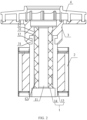
FIG. 2 is a schematic structural diagram of a rotor assembly provided by an embodiment of the present disclosure. -
FIG. 3 is an exploded schematic diagram of a partial structure of a rotor assembly provided by an embodiment of the present disclosure. -
FIG. 4 is a partial structural schematic diagram of another rotor assembly provided by an embodiment of the present disclosure. -
FIG. 5 is a schematic structural diagram of another rotor assembly provided by an embodiment of the present disclosure. -
FIG. 6 is a partial structural schematic diagram of a rotor assembly provided by an embodiment of the present disclosure. -
- 1. Bearing assembly; 2. Magnetic ring assembly; 3. Impeller seat; 4. Impeller cover;
- 11. First central through hole; 12. First limiting part; 13. Shaft sleeve; 14. Bearing;
- 21. Iron core assembly; 22. First cover plate; 23. Second cover plate; 24. Sleeve;
- 31. Second limiting part; 32. Bushing.
- Example embodiments will now be described more fully with reference to the accompanying drawings. Example embodiments may, however, be embodied in various forms and should not be construed as limited to the embodiments set forth herein; rather, these embodiments are provided so that the present disclosure will be thorough and complete and will fully convey the concepts of the example embodiments to those skilled in the art. The same reference numerals in the drawings indicate the same or similar structures, and thus their detailed descriptions will be omitted. Furthermore, the drawings are merely schematic illustrations of the present disclosure and are not necessarily drawn to scale.
- Although relative terms, such as "up" and "down" are used in this specification to describe the relative relationship of one component indicated by an icon to another component, these terms are used in this specification only for convenience. For example, according to the direction of the example described in drawings, it will be understood that if the device indicated by the icon is turned upside down, the component described as being "up" would become the component being "down". When a structure is "on" another structure, it may mean that the structure is integrally formed on the other structure, or that the structure is "directly" placed on the other structure, or that the structure is "indirectly" placed on the other structure through another structure.
- The terms "a", "an", "the", "said" and "at least one" are used to indicate the presence of one or more elements/components/etc. The terms "include" and "have" are used to indicate an open-ended sense of inclusion and mean that there may be additional elements/components/etc. in addition to those listed. The terms "first", "second", "third" etc. are only used as a marker, and not as quantitative limitations on their objects.
- The embodiment of the present disclosure provides an electronic water pump, including a housing and a rotor assembly. The housing has an inner cavity and a rotating shaft located in the inner cavity. The rotor assembly is accommodated in the inner cavity and is rotatably sleeved on the rotating shaft.
- The housing wall of the housing has a water inlet and a water outlet that communicate with the inner cavity. When the electronic water pump is in operation, the rotor assembly is connected to the external power supply and rotates. The fluid enters the inner cavity of the housing along the water inlet. At this time, the rotor assembly converts its own mechanical energy into kinetic energy of the fluid to promote the fluid to flow out along the water outlet at a higher flow rate.
- The specific structure of the housing can refer to the related art. The rotor assembly mainly includes a
shaft sleeve 13, amagnetic ring assembly 2, animpeller seat 3 and animpeller cover 4. Themagnetic ring assembly 2 includes an iron core and magnetic steel. For details, see the embodiment shown inFIG. 2 below. - In the related art, the rotor assembly is molded by at least two injection molding processes. As shown in
FIG. 1 , the magnetic ring assembly 2 (iron core and magnet steel) is first injection molded as an embedded part to obtain a first injection molded part including the impeller seat 3 (containing part) and the magnetic ring assembly 2 (contained part). Then, the first injection molded part obtained by injection molding is used as an embedded part to obtain a second injection molded part including the first injection molded part (contained part) and the shaft sleeve 13 (containing part). Finally, theimpeller cover 4 is fixed on theimpeller seat 3 of the second injection molded part to obtain the rotor assembly. - In the related art, at least two insert injection molding processes are required to produce the rotor assembly. The inventor found that it is difficult to ensure the coaxiality of the containing part and the contained part during the insert injection molding process. Therefore, the more times insert injection molding processes are performed, the more difficult it is to ensure the dynamic balance accuracy of the rotor assembly. In this way, the electronic water pump with the rotor assembly will vibrate during operation, thereby reducing the service life of the electronic water pump. In addition, it will make a lot of noise and cause environmental pollution.
-
FIG. 2 shows a schematic structural diagram of a rotor assembly of an electronic water pump according to an embodiment of the present disclosure. As shown inFIG. 2 , the rotor assembly includes a bearingassembly 1, amagnetic ring assembly 2, animpeller seat 3 and animpeller cover 4. The bearingassembly 1 has a first central throughhole 11. The first central throughhole 11 is configured to be sleeved on the rotating shaft, and the end of the bearingassembly 1 has a first limitingpart 12. Themagnetic ring assembly 2 is sleeved on the bearingassembly 1. Themagnetic ring assembly 2 is interference-fitted with the bearingassembly 1. At least one end of the bearingassembly 1 extends out of themagnetic ring assembly 2. Theimpeller seat 3 wraps the end of the bearingassembly 1, and theimpeller seat 3 has a second limitingpart 31 in limiting fit with the first limitingpart 12 for limiting purpose. Theimpeller cover 4 is fixedly connected to a side of theimpeller seat 3 away from the bearingassembly 1. - In the embodiment of the present disclosure, the coaxiality between the
magnetic ring assembly 2 and the bearingassembly 1 is ensured through the interference-fit between themagnetic ring assembly 2 and the bearingassembly 1, and then themagnetic ring assembly 2 and the bearingassembly 1 which are interference-fitted are connected to theimpeller seat 3. Therefore, in the embodiment of the present disclosure, the number of insert injection molding processes can be reduced when the rotor assembly is produced, thereby ensuring the dynamic balance accuracy of the rotor assembly, avoiding vibration of the electronic water pump with the rotor assembly during operation, and extending the service life of the electronic water pump while avoiding noise pollution to the environment. In addition, in the embodiment of the present disclosure, after theimpeller seat 3 is formed by injection molding on the first end of the bearingassembly 1, the relative rotation between the bearingassembly 1 and theimpeller seat 3 can be limited by the cooperation of the first limitingpart 12 and the second limitingpart 31, thereby avoiding the phenomenon of slipping between the bearingassembly 1 and theimpeller seat 3, and ensuring the efficiency of the rotor assembly. - The first limiting
part 12 is a limiting groove, and the second limitingpart 31 is a limiting block; or, the first limitingpart 12 is a limiting block, and the second limitingpart 31 is a limiting groove, as long as a limit fit of the first limitingpart 12 and the second limitingpart 31 can be realized, and the embodiment of the present disclosure is not limited to this. The first end of the bearingassembly 1 extends out of themagnetic ring assembly 2, and the second end of the bearingassembly 1 extends out of themagnetic ring assembly 2 or is flush with the end surface of themagnetic ring assembly 2. - In the embodiment of the present disclosure, the
impeller cover 4 and theimpeller seat 3 are welded and fixed. Specifically, theimpeller cover 4 and theimpeller seat 3 are fixed by ultrasonic welding. Of course, other connection methods are also possible, as long as the fixed connection between the impeller cover and the impeller seat can be achieved, and the embodiment of the present disclosure is not limited to this. - In some embodiments, as shown in
FIG. 3 , themagnetic ring assembly 2 mainly includes aniron core assembly 21. Theiron core assembly 21 has a second central through hole. Theiron core assembly 21 is sleeved on the bearingassembly 1 based on the second central through hole. Theiron core assembly 21 is interference-fitted with the bearingassembly 1 to ensure the coaxiality between theiron core assembly 21 and the bearingassembly 1. - The
iron core assembly 21 includes the above-mentioned iron core and magnetic steel. The iron core and the magnetic steel can be produced in advance through an one-piece molding process to ensure the coaxiality of the iron core and the magnetic steel. The one-piece molding process of the iron core and the magnetic steel can refer to the related art. Of course, the iron core and the magnetic steel can also be obtained through other processes, as long as the coaxiality of the iron core and the magnetic field can be ensured, and the embodiment of the present disclosure is not limited to this. - In some examples, the inner wall of the second central through hole has a protrusion, and the outer wall of the bearing
assembly 1 has a groove that matches the protrusion; or the inner wall of the second central through hole has a groove, and the outer wall of the bearingassembly 1 has a protrusion that matches the groove. The protrusion and groove are all along the axial direction of the second central through hole. In this way, through the cooperation of the protrusion and the groove, the contact area between theiron core assembly 21 and the bearingassembly 1 is increased, while relative rotation of theiron core assembly 21 and the bearingassembly 1 is further prevented. - In order to achieve sealing of the
iron core assembly 21, as shown inFIG. 3 , themagnetic ring assembly 2 also includes afirst cover plate 22, asecond cover plate 23 and asleeve 24. Thefirst cover plate 22 and thesecond cover plate 23 are sleeved on the bearingassembly 1 and are respectively located at both ends of theiron core assembly 21. That is, thefirst cover plate 22, theiron core assembly 21, and thesecond cover plate 23 included in themagnetic ring assembly 2 are sleeved on the bearingassembly 1 in sequence, and the inner circle of thefirst cover plate 22 and the inner circle of thesecond cover plate 23 are sealed and fixedly connected to the bearingassembly 1. Thesleeve 24 is sleeved on theiron core assembly 21, and thesleeve 24 is sealed and fixedly connected to the outer circle of thefirst cover plate 22 and the outer circle of thesecond cover plate 23 respectively. - In this way, through the connection of the
first cover plate 22 and thesecond cover plate 23 to the bearingassembly 1 respectively, and the connection of thefirst cover plate 22 and thesecond cover plate 23 to thesleeve 24 respectively, a sealing cavity for accommodating theiron core assembly 21 can be formed, so as to achieve the sealing protection of theiron core assembly 21. - All of the connection between the
first cover plate 22 the bearingassembly 1, the connection between thesecond cover plate 23 and the bearingassembly 1, the connection between thefirst cover plate 22 and thesleeve 24, and the connection between thesecond cover plate 23 and thesleeve 24 can be welded. Specifically, laser welding can be used. Of course, other connection methods are also possible, as long as the sealing protection of theiron core assembly 21 can be achieved, and the embodiment of the present disclosure is not limited to this. - In some embodiments, as shown in
FIG. 4 orFIG. 5 , the bearingassembly 1 includes ashaft sleeve 13. Theshaft sleeve 13 has a first central throughhole 11, and the end of theshaft sleeve 13 has a first limitingpart 12. Theshaft sleeve 13 is configured to be rotatably sleeved on the rotating shaft. - The
shaft sleeve 13 can be configured as an embedded part, and theimpeller seat 3 is formed on the end of theshaft sleeve 13 through an insert injection molding process. Of course, theimpeller seat 3 can also be obtained by pre-injection molding, and then theimpeller seat 3 is connected to the end of theshaft sleeve 13 while ensuring the limiting fit of the first limitingpart 12 and the second limitingpart 31. - Since both the
shaft sleeve 13 and the rotating shaft are rigid parts, the friction between theshaft sleeve 13 and the rotating shaft is relatively large when the rotor assembly rotates. Therefore, in order to reduce the friction between theshaft sleeve 13 and the rotating shaft, when theimpeller seat 3 is formed by injection molding, as shown inFIG. 4 orFIG. 5 , abushing 32 is also formed on the inner wall of the first central throughhole 11. That is to say, theimpeller seat 3 has abushing 32 extending along the axial direction of theshaft sleeve 13 and fitting with the hole wall of the first central throughhole 11. In this way, when the rotor assembly rotates, thebushing 32 is in direct contact with the rotating shaft and rotates relatively, thereby avoiding contact between theshaft sleeve 13 and the rotating shaft. - When the
bushing 32 rotates relative to the rotating shaft, in order to avoid wear of thebushing 32 and reduce friction at the same time, a material with good mechanical property such as high temperature resistance and wear resistance can be selected for injection molding to form theimpeller seat 3 with thebushing 32. For example, the material of theimpeller seat 3 includes PPS (Polyphenylene sulphide). - In other embodiments, as shown in
FIG. 2 or6 , the bearingassembly 1 includes ashaft sleeve 13 and abearing 14. Thebearing 14 has a first central throughhole 11. Theshaft sleeve 13 is sleeved on thebearing 14 and interference-fitted with thebearing 14. Theimpeller seat 3 wraps at least one of the end of thebearing 14 and the end of theshaft sleeve 13. - The interference-fit between the
shaft sleeve 13 and thebearing 14 can ensure the coaxiality of theshaft sleeve 13 and thebearing 14 to ensure the dynamic balance accuracy of the rotor assembly. Thebearing 14 is configured to be rotatable limited on the rotating shaft. The first end of thebearing 14 and/or the first end of theshaft sleeve 13 can be injection molded as an embedded part to obtain theimpeller seat 3. - In some embodiments, at least one of the outer wall of the
bearing 14 and the outer wall of theshaft sleeve 13 has a first limitingpart 12. The outer wall of thebearing 14 and the outer wall of theshaft sleeve 13 can be specifically determined according to the positional relationship between the bearing 14 and theshaft sleeve 13. - The first end of the
bearing 14 extends out of the first end of theshaft sleeve 13. At this time, the first end of thebearing 14 is wrapped by theimpeller seat 3, and the first end of thebearing 14 has a first limitingpart 12, so that the first limitingpart 12 of thebearing 14 cooperates with the second limitingpart 31 on theimpeller seat 3 for limiting purpose. Alternatively, as shown inFIG. 2 , the first end of thebearing 14 and the first end of theshaft sleeve 13 are both wrapped by theimpeller seat 3, and the first end of thebearing 14 and the first end of theshaft sleeve 13 both have a first limitingpart 12, so that the first limitingpart 12 on theshaft sleeve 13 and the first limitingpart 12 on thebearing 14 cooperate with the second limitingpart 31 on theimpeller seat 3 for limiting purpose. - Of course, it is also possible that the first end of the
bearing 14 does not extend out of the first end of theshaft sleeve 13. In this case, the first end of theshaft sleeve 13 is wrapped by theimpeller seat 3, and the first end of theshaft sleeve 13 has a first limitingpart 12, so that the first limitingpart 12 at the first end of theshaft sleeve 13 cooperates with the second limitingpart 31 on theimpeller seat 3 for limiting purpose. - In the embodiment of the present disclosure, as shown in
FIG. 2 , first limitingparts 12 are provided on the outer side walls of thebearing 14 near both ends to prevent reverse mounting when thebearing 14 is assembled with theshaft sleeve 13, thus improving the assembly efficiency. - In order to reduce the friction between the bearing 14 and the rotating shaft when the rotor assembly rotates and avoid wear of the
bearing 14, a material with good mechanical property such as high temperature resistance, wear resistance, and self-lubrication can be selected to make thebearing 14. For example, the material of thebearing 14 is graphite, that is, thebearing 14 is a graphite bearing. - In some examples, in order to further ensure the tight fit between the
shaft sleeve 13 and thebearing 14, one of the outer wall of thebearing 14 and the inner wall of theshaft sleeve 13 has a groove, and the other has a protrusion limited in the groove. In this way, through the cooperation of the groove and the protrusion, the contact area between theshaft sleeve 13 and thebearing 14 is increased, and at the same time, the relative rotation of theshaft sleeve 13 and thebearing 14 is further prevented. In some embodiments, the side wall of the end of the bearingassembly 1 has a plurality of first limitingparts 12 in the circumferential direction, and theimpeller seat 3 has an embedded groove that accommodates the first end of the bearingassembly 1. The groove wall of the embedded groove has a plurality of second limitingparts 31 in the circumferential direction. In this way, the possibility of relative rotation between the bearingassembly 1 and theimpeller seat 3 can be avoided through the corresponding limiting of the plurality of first limitingparts 12 and the plurality of second limitingparts 31. Taking the first limitingpart 12 as a limiting groove and the second limitingpart 31 as a limiting block as an example, the plurality of second limitingparts 31 are correspondingly limited in the plurality of first limitingparts 12. - Of course, it is also possible that the side wall of the end of the bearing
assembly 1 has a plurality of first limitingparts 12 along the axial direction, and the groove wall of the embedded groove has a plurality of second limitingparts 31 in the axial direction, as long as it does not affect the formation of theimpeller seat 3 with the bearingassembly 1 as an embedded part, and the embodiment of the present disclosure is not limited to this. - The present disclosure has been described through the above-mentioned embodiments, but it should be understood that the above-mentioned embodiments are only for the purpose of examples and illustrations, and are not intended to limit the present disclosure to the scope of the described embodiments. In addition, those skilled in the art can understand that the present disclosure is not limited to the above embodiments, and more variations and modifications can be made according to the teachings of the present disclosure. These variations and modifications all fall within the protection scope of the present disclosure. The protection scope of the present disclosure is defined by the appended claims and their equivalent scope.
Claims (10)
- A rotor assembly of an electronic water pump, comprising:a bearing assembly comprising a first central through hole, wherein the first central through hole is configured to be sleeved on a rotating shaft, and an end of the bearing assembly has a first limiting part;a magnetic ring assembly sleeved on the bearing assembly, wherein the magnetic ring assembly is interference-fitted with the bearing assembly, and at least one end of the bearing assembly extends out of the magnetic ring assembly;an impeller seat wrapping the end of the bearing assembly, wherein the impeller seat has a second limiting part in limiting fit with the first limiting part; andan impeller cover fixedly connected to a side of the impeller seat away from the bearing assembly.
- The rotor assembly according to claim 1, wherein the bearing assembly comprises a shaft sleeve, and the impeller seat has a bushing extending along the axial direction of the shaft sleeve and fitting with a hole wall of the first central through hole.
- The rotor assembly according to claim 2, wherein a material of the impeller seat comprises polyphenylene sulfide.
- The rotor assembly according to claim 1, wherein the bearing assembly comprises a shaft sleeve and a bearing;the bearing has the first central through hole, the shaft sleeve is sleeved on the bearing and is interference-fitted with the bearing; andthe impeller seat wraps at least one of an end of the bearing and an end of the shaft sleeve.
- The rotor assembly according to claim 4, wherein the bearing is a graphite bearing.
- The rotor assembly according to claim 4, wherein one of an outer wall of the bearing and an inner wall of the shaft sleeve has a groove, and the other has a protrusion limited in the groove.
- The rotor assembly according to claim 4, wherein at least one of an outer wall of the bearing and an outer wall of the shaft sleeve has the first limiting part.
- The rotor assembly according to any one of claims 1 to 7, wherein a side wall of the end of the bearing assembly has a plurality of first limiting parts in a circumferential direction, and the impeller seat has an embedded groove accommodating the end of the bearing assembly, a groove wall of the embedded groove has a plurality of second limiting parts in the circumferential direction, and the plurality of second limiting parts are respectively limited within the plurality of the first limiting parts.
- The rotor assembly according to any one of claims 1 to 7, wherein the magnetic ring assembly comprises an iron core assembly, a first cover plate, a second cover plate and a sleeve;the first cover plate, the iron core assembly, and the second cover plate are sleeved on the bearing assembly in sequence, and the iron core assembly is interference-fitted with the bearing assembly, both of an inner circle of the first cover plate and an inner circle of the second cover plate are sealed and fixedly connected to the bearing assembly; andthe sleeve is sleeved on the iron core assembly, and the sleeve is sealed and fixedly connected to an outer circle of the first cover plate and an outer circle of the second cover plate respectively.
- An electronic water pump, comprising a housing and the rotor assembly according to any one of claims 1 to 9;
the housing has an inner cavity and a rotation shaft located in the inner cavity, and the rotor assembly is accommodated in the inner cavity and is rotatably sleeved on the rotation shaft.
Applications Claiming Priority (2)
| Application Number | Priority Date | Filing Date | Title |
|---|---|---|---|
| CN202122906945.8U CN216278538U (en) | 2021-11-22 | 2021-11-22 | Rotor assembly of electronic water pump and electronic water pump |
| PCT/CN2022/133383 WO2023088475A1 (en) | 2021-11-22 | 2022-11-22 | Rotor assembly of electronic water pump and electronic water pump |
Publications (1)
| Publication Number | Publication Date |
|---|---|
| EP4438902A1 true EP4438902A1 (en) | 2024-10-02 |
Family
ID=81037372
Family Applications (1)
| Application Number | Title | Priority Date | Filing Date |
|---|---|---|---|
| EP22895004.4A Withdrawn EP4438902A1 (en) | 2021-11-22 | 2022-11-22 | Rotor assembly of electronic water pump and electronic water pump |
Country Status (5)
| Country | Link |
|---|---|
| EP (1) | EP4438902A1 (en) |
| JP (1) | JP2024538995A (en) |
| KR (1) | KR20240090698A (en) |
| CN (1) | CN216278538U (en) |
| WO (1) | WO2023088475A1 (en) |
Families Citing this family (1)
| Publication number | Priority date | Publication date | Assignee | Title |
|---|---|---|---|---|
| CN216278538U (en) * | 2021-11-22 | 2022-04-12 | 盾安汽车热管理科技有限公司 | Rotor assembly of electronic water pump and electronic water pump |
Family Cites Families (19)
| Publication number | Priority date | Publication date | Assignee | Title |
|---|---|---|---|---|
| JP3151639B2 (en) * | 1992-10-08 | 2001-04-03 | アイシン精機株式会社 | Resin composition for automotive water pump related parts and automotive water pump related parts comprising the same |
| JPH10108436A (en) * | 1996-09-27 | 1998-04-24 | Hitachi Ltd | Brushless motor and brushless motor pump |
| DE10152497A1 (en) * | 2001-10-24 | 2003-05-15 | Pierburg Gmbh | Wet rotor |
| GB2418072B (en) * | 2004-09-14 | 2008-05-07 | Dana Automotive Ltd | Pump assembly |
| JP5750360B2 (en) * | 2011-11-07 | 2015-07-22 | アスモ株式会社 | Electric pump manufacturing method |
| JP5750359B2 (en) * | 2011-11-07 | 2015-07-22 | アスモ株式会社 | Electric pump |
| JP6022185B2 (en) * | 2012-03-30 | 2016-11-09 | 株式会社クボタ | Bearing device, pump, assembling method of bearing device, and oil drain groove position adjusting method |
| CN111306071B (en) * | 2015-07-24 | 2021-06-15 | 浙江三花汽车零部件有限公司 | Rotor assembly and electronic pump |
| CN106555765A (en) * | 2015-09-30 | 2017-04-05 | 杭州三花研究院有限公司 | electric drive pump |
| CN205779911U (en) * | 2016-05-27 | 2016-12-07 | 合肥新沪屏蔽泵有限公司 | A kind of lightweight pump assembly |
| JP2018162744A (en) * | 2017-03-27 | 2018-10-18 | ケーピーエス工業株式会社 | pump |
| CN110971032A (en) * | 2018-09-30 | 2020-04-07 | 杭州三花研究院有限公司 | Rotor assembly and electric pump |
| CN114930031B (en) * | 2020-01-09 | 2025-03-11 | 盖茨公司 | Permanent magnet rotors for axial flux motors |
| JP7249305B2 (en) * | 2020-03-31 | 2023-03-30 | 日立Astemo株式会社 | electric liquid feed pump |
| CN113595337A (en) * | 2020-04-30 | 2021-11-02 | 杭州三花研究院有限公司 | Method for manufacturing rotor assembly |
| CN213331654U (en) * | 2020-09-01 | 2021-06-01 | 瑞立集团瑞安汽车零部件有限公司 | Rotor rotating shaft and rotor assembly |
| CN213870317U (en) * | 2020-11-02 | 2021-08-03 | 江苏朗信电气有限公司 | A rotor assembly of a high-power brushless electronic water pump and its installation structure |
| CN112268004B (en) * | 2020-11-02 | 2025-03-14 | 江苏朗信电气股份有限公司 | A high-power brushless electronic water pump |
| CN216278538U (en) * | 2021-11-22 | 2022-04-12 | 盾安汽车热管理科技有限公司 | Rotor assembly of electronic water pump and electronic water pump |
-
2021
- 2021-11-22 CN CN202122906945.8U patent/CN216278538U/en active Active
-
2022
- 2022-11-22 EP EP22895004.4A patent/EP4438902A1/en not_active Withdrawn
- 2022-11-22 JP JP2024522039A patent/JP2024538995A/en active Pending
- 2022-11-22 WO PCT/CN2022/133383 patent/WO2023088475A1/en not_active Ceased
- 2022-11-22 KR KR1020247016870A patent/KR20240090698A/en active Pending
Also Published As
| Publication number | Publication date |
|---|---|
| CN216278538U (en) | 2022-04-12 |
| KR20240090698A (en) | 2024-06-21 |
| JP2024538995A (en) | 2024-10-28 |
| WO2023088475A1 (en) | 2023-05-25 |
Similar Documents
| Publication | Publication Date | Title |
|---|---|---|
| CN210196043U (en) | water pump | |
| JP7492078B2 (en) | Rotor assembly and electric water pump | |
| CN104184248B (en) | Motor and its end cover bearing connection structure | |
| EP4438902A1 (en) | Rotor assembly of electronic water pump and electronic water pump | |
| KR101527529B1 (en) | Water pump | |
| CN221400961U (en) | Magnetic pump | |
| CN219948534U (en) | Shaftless propeller driven by intermediate rotor axial flux motor | |
| KR20030011713A (en) | Fuel pump | |
| CN219948535U (en) | Shaftless propeller driven by middle stator axial flux motor | |
| CN1644929B (en) | Fuel pump received in housing | |
| CN217522720U (en) | Hollow cup type brushless sensor motor | |
| KR101198612B1 (en) | Spindle motor | |
| CN224149797U (en) | Rotor assembly and electric water pump | |
| CN219717963U (en) | Hydrogen embrittlement-preventing rotor structure of axial motor of hydrogen circulation pump | |
| CN222863670U (en) | Shaft core, pump chamber structure using the shaft core, and electronic water pump | |
| CN219139452U (en) | Rotor assembly and centrifugal pump | |
| CN221400955U (en) | Pump device | |
| CN205331003U (en) | Shielding formula is rotor subassembly for electronic pump | |
| CN216216137U (en) | Rotor with built-in bearing and centrifugal pump | |
| CN219974618U (en) | Electronic water pump, thermal management system and vehicle | |
| CN221575025U (en) | Underwater brushless motor | |
| JP5204718B2 (en) | Fuel pump | |
| CN223724941U (en) | Pump cover assembly and electronic water pump using it | |
| CN221857006U (en) | Waterproof centrifugal water pump | |
| CN220850051U (en) | Electric water pump |
Legal Events
| Date | Code | Title | Description |
|---|---|---|---|
| STAA | Information on the status of an ep patent application or granted ep patent |
Free format text: STATUS: THE INTERNATIONAL PUBLICATION HAS BEEN MADE |
|
| PUAI | Public reference made under article 153(3) epc to a published international application that has entered the european phase |
Free format text: ORIGINAL CODE: 0009012 |
|
| STAA | Information on the status of an ep patent application or granted ep patent |
Free format text: STATUS: REQUEST FOR EXAMINATION WAS MADE |
|
| 17P | Request for examination filed |
Effective date: 20240621 |
|
| AK | Designated contracting states |
Kind code of ref document: A1 Designated state(s): AL AT BE BG CH CY CZ DE DK EE ES FI FR GB GR HR HU IE IS IT LI LT LU LV MC ME MK MT NL NO PL PT RO RS SE SI SK SM TR |
|
| STAA | Information on the status of an ep patent application or granted ep patent |
Free format text: STATUS: THE APPLICATION HAS BEEN WITHDRAWN |
|
| 18W | Application withdrawn |
Effective date: 20241120 |