EP4438417A1 - Airbag device - Google Patents
Airbag device Download PDFInfo
- Publication number
- EP4438417A1 EP4438417A1 EP23187475.1A EP23187475A EP4438417A1 EP 4438417 A1 EP4438417 A1 EP 4438417A1 EP 23187475 A EP23187475 A EP 23187475A EP 4438417 A1 EP4438417 A1 EP 4438417A1
- Authority
- EP
- European Patent Office
- Prior art keywords
- tether
- airbag cushion
- seatback
- foam pad
- airbag
- Prior art date
- Legal status (The legal status is an assumption and is not a legal conclusion. Google has not performed a legal analysis and makes no representation as to the accuracy of the status listed.)
- Granted
Links
Images




Classifications
-
- B—PERFORMING OPERATIONS; TRANSPORTING
- B60—VEHICLES IN GENERAL
- B60R—VEHICLES, VEHICLE FITTINGS, OR VEHICLE PARTS, NOT OTHERWISE PROVIDED FOR
- B60R21/00—Arrangements or fittings on vehicles for protecting or preventing injuries to occupants or pedestrians in case of accidents or other traffic risks
- B60R21/02—Occupant safety arrangements or fittings, e.g. crash pads
- B60R21/16—Inflatable occupant restraints or confinements designed to inflate upon impact or impending impact, e.g. air bags
- B60R21/23—Inflatable members
- B60R21/231—Inflatable members characterised by their shape, construction or spatial configuration
- B60R21/233—Inflatable members characterised by their shape, construction or spatial configuration comprising a plurality of individual compartments; comprising two or more bag-like members, one within the other
-
- B—PERFORMING OPERATIONS; TRANSPORTING
- B60—VEHICLES IN GENERAL
- B60R—VEHICLES, VEHICLE FITTINGS, OR VEHICLE PARTS, NOT OTHERWISE PROVIDED FOR
- B60R21/00—Arrangements or fittings on vehicles for protecting or preventing injuries to occupants or pedestrians in case of accidents or other traffic risks
- B60R21/02—Occupant safety arrangements or fittings, e.g. crash pads
- B60R21/16—Inflatable occupant restraints or confinements designed to inflate upon impact or impending impact, e.g. air bags
- B60R21/23—Inflatable members
- B60R21/231—Inflatable members characterised by their shape, construction or spatial configuration
- B60R21/2334—Expansion control features
- B60R21/2338—Tethers
-
- B—PERFORMING OPERATIONS; TRANSPORTING
- B60—VEHICLES IN GENERAL
- B60R—VEHICLES, VEHICLE FITTINGS, OR VEHICLE PARTS, NOT OTHERWISE PROVIDED FOR
- B60R21/00—Arrangements or fittings on vehicles for protecting or preventing injuries to occupants or pedestrians in case of accidents or other traffic risks
- B60R21/02—Occupant safety arrangements or fittings, e.g. crash pads
- B60R21/16—Inflatable occupant restraints or confinements designed to inflate upon impact or impending impact, e.g. air bags
- B60R21/20—Arrangements for storing inflatable members in their non-use or deflated condition; Arrangement or mounting of air bag modules or components
- B60R21/207—Arrangements for storing inflatable members in their non-use or deflated condition; Arrangement or mounting of air bag modules or components in vehicle seats
-
- B—PERFORMING OPERATIONS; TRANSPORTING
- B60—VEHICLES IN GENERAL
- B60R—VEHICLES, VEHICLE FITTINGS, OR VEHICLE PARTS, NOT OTHERWISE PROVIDED FOR
- B60R21/00—Arrangements or fittings on vehicles for protecting or preventing injuries to occupants or pedestrians in case of accidents or other traffic risks
- B60R21/02—Occupant safety arrangements or fittings, e.g. crash pads
- B60R21/16—Inflatable occupant restraints or confinements designed to inflate upon impact or impending impact, e.g. air bags
- B60R21/20—Arrangements for storing inflatable members in their non-use or deflated condition; Arrangement or mounting of air bag modules or components
- B60R21/215—Arrangements for storing inflatable members in their non-use or deflated condition; Arrangement or mounting of air bag modules or components characterised by the covers for the inflatable member
- B60R21/2165—Arrangements for storing inflatable members in their non-use or deflated condition; Arrangement or mounting of air bag modules or components characterised by the covers for the inflatable member characterised by a tear line for defining a deployment opening
-
- B—PERFORMING OPERATIONS; TRANSPORTING
- B60—VEHICLES IN GENERAL
- B60R—VEHICLES, VEHICLE FITTINGS, OR VEHICLE PARTS, NOT OTHERWISE PROVIDED FOR
- B60R21/00—Arrangements or fittings on vehicles for protecting or preventing injuries to occupants or pedestrians in case of accidents or other traffic risks
- B60R21/02—Occupant safety arrangements or fittings, e.g. crash pads
- B60R21/16—Inflatable occupant restraints or confinements designed to inflate upon impact or impending impact, e.g. air bags
- B60R21/23—Inflatable members
- B60R21/231—Inflatable members characterised by their shape, construction or spatial configuration
-
- B—PERFORMING OPERATIONS; TRANSPORTING
- B60—VEHICLES IN GENERAL
- B60R—VEHICLES, VEHICLE FITTINGS, OR VEHICLE PARTS, NOT OTHERWISE PROVIDED FOR
- B60R21/00—Arrangements or fittings on vehicles for protecting or preventing injuries to occupants or pedestrians in case of accidents or other traffic risks
- B60R21/02—Occupant safety arrangements or fittings, e.g. crash pads
- B60R21/16—Inflatable occupant restraints or confinements designed to inflate upon impact or impending impact, e.g. air bags
- B60R21/23—Inflatable members
- B60R21/231—Inflatable members characterised by their shape, construction or spatial configuration
- B60R21/23138—Inflatable members characterised by their shape, construction or spatial configuration specially adapted for side protection
-
- B—PERFORMING OPERATIONS; TRANSPORTING
- B60—VEHICLES IN GENERAL
- B60R—VEHICLES, VEHICLE FITTINGS, OR VEHICLE PARTS, NOT OTHERWISE PROVIDED FOR
- B60R21/00—Arrangements or fittings on vehicles for protecting or preventing injuries to occupants or pedestrians in case of accidents or other traffic risks
- B60R21/02—Occupant safety arrangements or fittings, e.g. crash pads
- B60R21/16—Inflatable occupant restraints or confinements designed to inflate upon impact or impending impact, e.g. air bags
- B60R21/23—Inflatable members
- B60R21/231—Inflatable members characterised by their shape, construction or spatial configuration
- B60R21/2334—Expansion control features
- B60R21/2342—Tear seams
-
- B—PERFORMING OPERATIONS; TRANSPORTING
- B60—VEHICLES IN GENERAL
- B60R—VEHICLES, VEHICLE FITTINGS, OR VEHICLE PARTS, NOT OTHERWISE PROVIDED FOR
- B60R21/00—Arrangements or fittings on vehicles for protecting or preventing injuries to occupants or pedestrians in case of accidents or other traffic risks
- B60R21/02—Occupant safety arrangements or fittings, e.g. crash pads
- B60R21/16—Inflatable occupant restraints or confinements designed to inflate upon impact or impending impact, e.g. air bags
- B60R21/23—Inflatable members
- B60R21/237—Inflatable members characterised by the way they are folded
-
- B—PERFORMING OPERATIONS; TRANSPORTING
- B60—VEHICLES IN GENERAL
- B60N—SEATS SPECIALLY ADAPTED FOR VEHICLES; VEHICLE PASSENGER ACCOMMODATION NOT OTHERWISE PROVIDED FOR
- B60N2/00—Seats specially adapted for vehicles; Arrangement or mounting of seats in vehicles
- B60N2/58—Seat coverings
- B60N2002/5808—Seat coverings comprising opening zones for airbags
-
- B—PERFORMING OPERATIONS; TRANSPORTING
- B60—VEHICLES IN GENERAL
- B60R—VEHICLES, VEHICLE FITTINGS, OR VEHICLE PARTS, NOT OTHERWISE PROVIDED FOR
- B60R21/00—Arrangements or fittings on vehicles for protecting or preventing injuries to occupants or pedestrians in case of accidents or other traffic risks
- B60R21/02—Occupant safety arrangements or fittings, e.g. crash pads
- B60R21/16—Inflatable occupant restraints or confinements designed to inflate upon impact or impending impact, e.g. air bags
- B60R21/23—Inflatable members
- B60R21/231—Inflatable members characterised by their shape, construction or spatial configuration
- B60R2021/23107—Inflatable members characterised by their shape, construction or spatial configuration the bag being integrated in a multi-bag system
-
- B—PERFORMING OPERATIONS; TRANSPORTING
- B60—VEHICLES IN GENERAL
- B60R—VEHICLES, VEHICLE FITTINGS, OR VEHICLE PARTS, NOT OTHERWISE PROVIDED FOR
- B60R21/00—Arrangements or fittings on vehicles for protecting or preventing injuries to occupants or pedestrians in case of accidents or other traffic risks
- B60R21/02—Occupant safety arrangements or fittings, e.g. crash pads
- B60R21/16—Inflatable occupant restraints or confinements designed to inflate upon impact or impending impact, e.g. air bags
- B60R21/23—Inflatable members
- B60R21/231—Inflatable members characterised by their shape, construction or spatial configuration
- B60R21/23138—Inflatable members characterised by their shape, construction or spatial configuration specially adapted for side protection
- B60R2021/23146—Inflatable members characterised by their shape, construction or spatial configuration specially adapted for side protection seat mounted
-
- B—PERFORMING OPERATIONS; TRANSPORTING
- B60—VEHICLES IN GENERAL
- B60R—VEHICLES, VEHICLE FITTINGS, OR VEHICLE PARTS, NOT OTHERWISE PROVIDED FOR
- B60R21/00—Arrangements or fittings on vehicles for protecting or preventing injuries to occupants or pedestrians in case of accidents or other traffic risks
- B60R21/02—Occupant safety arrangements or fittings, e.g. crash pads
- B60R21/16—Inflatable occupant restraints or confinements designed to inflate upon impact or impending impact, e.g. air bags
- B60R21/23—Inflatable members
- B60R21/231—Inflatable members characterised by their shape, construction or spatial configuration
- B60R21/2334—Expansion control features
- B60R21/2338—Tethers
- B60R2021/23386—External tether means
Definitions
- the present disclosure relates to an airbag device in which a folding position of a tether is improved so that the tether is unfolded while stably cutting a covering.
- a lateral chamber is connected to a front chamber to constitute an airbag cushion.
- the airbag cushion is folded at left and right sides of a seat. In the event of a collision of a vehicle, the airbag cushion is deployed toward the front side of the passenger and surrounds the lateral sides and the front side of the passenger, thereby protecting the passenger.
- a tether is connected to the lateral chamber and/or the front chamber, and an outward rotation of the chamber is restrained by the tether, thereby regulating a deployment shape of the airbag cushion.
- the present disclosure is proposed to solve these problems and aims to provide an airbag device in which a folding position of a tether is improved so that the tether unfolds as it cuts through a covering.
- an airbag device including: a foam pad embedded in a seatback; an airbag cushion folded at a lateral side of the foam pad and configured to be deployed forward; a covering shaped to cover the foam pad and configured to cover the seatback; and a tether positioned between the foam pad and the covering and connected between the seatback and the airbag cushion, the tether being configured to unfold while cutting through the covering when the airbag cushion is deployed.
- a slit which has a shape opened forward, may be formed in a boundary portion between the airbag cushion and the foam pad, and the tether may pass through the slit when it unfolds.
- the slit may be formed in the foam pad.
- a position regulation groove may be formed in a portion of the foam pad that faces the covering, and the tether may be positioned in the position regulation groove when folded.
- the position regulation groove may be formed in a portion of the foam pad that adjoins the slit.
- the tether may include an upper tether extending upward from an upper end of the airbag cushion along a rim of the seatback and connected to an upper end of a seatback frame.
- the upper tether may be connected to an upper end of the seatback positioned relatively distant from the airbag cushion.
- a tether tear line may be sewn to the covering along the tether, and the tether may unfold while cutting through the tether tear line.
- the tether may include a lower tether extending downward from a lower end of the airbag cushion along a rim of the seatback and connected to a lower end of a seatback frame.
- the airbag cushion may include a lateral chamber configured to be deployed in a shape that covers a lateral side of a seat, and a front chamber configured to be deployed in a shape that covers a front side of the seat, the upper tether may be connected to an upper end of the deployed front chamber and connected to an inner surface of the lateral chamber extending to the upper end of the front chamber, and the lower tether may be connected to a lower end of the deployed front chamber and connected to the inner surface of the lateral chamber extending to the lower end of the front chamber.
- the middle portion of the tether extending between the airbag cushion and the seatback is positioned between the foam pad and the covering. Therefore, when the airbag cushion is deployed, the tether is unfolded while cutting through only the covering, such that a relatively high force is not required to deploy the tether. Therefore, the deployment performance of the tether is improved, and the airbag cushion is prevented from being abnormally deployed.
- an airbag cushion 200 includes a lateral chamber 200a configured to be deployed in a shape that covers a lateral side of a seat, and a front chamber 200b configured to be deployed in a shape that covers a front side of the seat.
- the lateral chamber 200a is deployed to be elongated in an upward/downward longitudinal direction while being deployed forward from a left or right side of a seatback 10.
- the lateral chamber 200a is deployed to a space between a passenger and a vehicle structure such as a door and a center console and protects the passenger's head, shoulder, chest, abdomen, and pelvis that are main parts of the lateral side of the passenger.
- the front chambers 200b are respectively connected to front ends of the lateral chambers 200a disposed at the left and right sides and configured to be deployed in shapes shape bent toward the front side of the passenger.
- the front chamber 200b is deployed to protect a region from the passenger's shoulder to the passenger's abdomen.
- the lateral chambers 200a and the front chambers 200b are deployed in shapes that entirely surround the passenger's two opposite sides and the passenger's front side.
- the airbag directly restrains the passenger in accordance with various positions of the seat and various postures of the passenger, thereby safely protecting the passenger while coping with various collision modes. Therefore, the airbag may be substituted for a seat belt as well as airbags disposed at the other portions, thereby greatly improving marketability.
- tethers 300 together with the airbag cushions 200, are embedded in the seatback 10.
- the tethers 300 are unfolded while cutting through the seatback 10 when the airbag is deployed, thereby regulating deployment shapes of the airbag cushions 200.
- an airbag device of the present disclosure includes: a foam pad 100 embedded in the seatback 10; the airbag cushions 200 folded at lateral sides of the foam pad 100 and configured to be deployed forward; a covering 400 shaped to cover the foam pad 100 and configured to cover the seatback 10; and the tether 300 positioned between the foam pad 100 and the covering 400 and connected between the seatback 10 and the airbag cushion 200, the tether 300 being configured to be unfolded while cutting the covering 400 when the airbag cushion 200 is deployed.
- the foam pad 100 is embedded in the seatback 10 and implements a shape of the seatback 10.
- the airbag cushions 200 are folded at left and right positions of the foam pad 100, and the airbag cushion 200 may be assembled to left and right seatback frames 11.
- the seatback 10 is covered by the covering 400, such that the airbag cushions 200, together with the foam pad 100, are covered by the covering 400.
- one end of the tether 300 is fixed to the airbag cushion 200, and the other end of the tether 300 is fixed to an upper end of the seatback 10.
- a middle portion of the tether 300 which extends between the airbag cushion 200 and the seatback 10, is positioned between the foam pad 100 and the covering 400. That is, the tether 300 is positioned on a rear surface of the covering 400, and the tether 300 passes through a part where the foam pad 100 and the covering 400 overlap each other.
- the tether 300 when the airbag cushion 200 is deployed, the tether 300 is unfolded while cutting only the covering 400, such that a relatively high force is not required to deploy the tether 300. Therefore, the deployment performance of the tether 300 may be improved, such that the airbag cushion 200 may be normally deployed.
- a slit 110 which has a shape opened forward, is formed in a boundary portion between the airbag cushion 200 and the foam pad 100, and the tether 300 passes through the slit 110.
- the tether 300 fixed to the airbag cushion 200 adjoins the slit 110, such that the tether 300 is positioned in a form accommodated in the slit 110. Further, the tether 300 having passed through the slit 110 is positioned between the foam pad 100 and the covering 400.
- the slit 110 may be formed in a groove shape opened forward, and a gap of the slit 110 in a width direction of the slit 110 may be formed to be at least larger than a thickness of the tether 300.
- the tether 300 positioned in the slit 110 is unfolded while being easily extended to a front side of the slit 110 while the airbag cushion 200 is deployed, such that the deployment performance of the tether 300 is improved, and the airbag cushion 200 is more stably deployed.
- the slit 110 may be formed in the foam pad 100.
- the slits 110 may be formed in a forward/rearward direction and disposed at the left and right sides of the foam pad 100.
- the slit 110 may be formed to an end of the rear surface of the foam pad 100.
- the slit 110 may be formed only to a predetermined depth in the foam pad 100 so that a thickness of the foam pad 100 at the portion of the slit 110 is smaller than a thickness of the foam pad 100 at the periphery, such that the function of the slit 110 may be implemented.
- a position regulation groove 120 is formed in a portion of the foam pad 100 that faces the covering 400, such that the tether 300 may be positioned in the position regulation groove 120.
- the position regulation groove 120 which is recessed concavely, is formed in the portion of the foam pad 100 that faces the covering 400 and allows the tether 300 to pass therethrough.
- the position of the tether 300 is regulated between the foam pad 100 and the covering 400, thereby improving assembling properties and workability of the tether 300.
- the position regulation groove 120 may be formed in the foam pad 100 that adjoins the slit 110.
- the position regulation groove 120 extends to a front end of the slit 110, the tether 300 fixed to the airbag cushion 200 enters the position regulation groove 120 immediately after passing through the slit 110.
- the regulation of the position of the tether 300 is more easily and conveniently performed, such that assembling properties and workability of the tether 300 are further improved.
- the tethers 300 may include upper tethers 300a extending upwardly from upper ends of the airbag cushions 200 along a rim of the seatback 10 and connected to an upper end of the seatback frame 11.
- one end of the upper tether 300a is fixed to the upper end of the airbag cushion 200, and the other end of the upper tether 300a extends to the upper end of the seatback 10 and is fixed to the upper end of the seatback frame 11.
- one end of the upper tether 300a is fixed to an upper end of the front chamber 200b and fixed to an inner surface of the lateral chamber 200a extending to the upper end of the front chamber 200b, and the other end of the upper tether 300a is fixed at one point on the seatback frame 11, such that the upper tether 300a is deployed in a triangular surface shape.
- the upper tether 300a extends from the upper end of the seatback 10, passes over the passenger's shoulder, and is fixed to the airbag cushion 200 that covers the passenger's front and lateral sides, thereby regulating a deployment shape of an upper end of the airbag cushion 200.
- the upper tether 300a may be connected to the upper end of the seatback 10 positioned to be relatively distant from the airbag cushion 200.
- the upper tether 300a fixed to the upper end of the left airbag cushion 200 is fixed to a right side of the upper end of the seatback 10
- the upper tether 300a fixed to the upper end of the right airbag cushion 200 is fixed to a left side of the upper end of the seatback 10.
- a fixing point of the upper tether 300a fixed to the seatback 10 is distant from a fixing point of the upper tether 300a fixed to the airbag cushion 200, such that the airbag cushion 200 may be pulled by the upper tether 300a with a higher force, which more assuredly regulates the outward spread of the airbag cushions 200.
- a tether tear line 420 is sewn to the covering 400 along the tether 300, such that the tether 300 may be unfolded while cutting the tether tear line 420.
- the tether tear line 420 may be formed by weakening a sewn line formed at the upper end of the seatback 10.
- cushion tear lines 410 are formed in an upward/downward longitudinal direction at the left and right sides of the seatback 10, such that the airbag cushion 200 is deployed forward while cutting the cushion tear line 410.
- the tether tear line 420 extends to upper portions of the cushion tear lines 410, such that the tether 300 is unfolded while cutting the tether tear line 420.
- the tether tear line 420 is formed while passing through the portion facing the slit 110.
- the airbag cushion 200 is deployed forward while cutting the cushion tear lines 410 of the covering 400 and the foam pad 100, and the upper tether 300a is deployed forward while cutting the tether tear line 420 of the covering 400, such that the airbag is normally and quickly deployed.
- the tethers 300 may include lower tethers 300b extending downwardly from lower ends of the airbag cushion 200 along the rim of the seatback 10 and connected to a lower end of the seatback frame 11.
- one end of the lower tether 300b is fixed to a lower end of the front chamber 200b and fixed to an inner surface of the lateral chamber 200a extending to the lower end of the front chamber 200b, and the other end of the lower tether 300b is fixed at one left or right point on the seatback frame 11, such that the lower tether 300b is deployed in a triangular surface shape.
- the lower tether 300b extends from the lower end of the seatback 10, passes over the passenger's thigh, and is fixed to the airbag cushion 200 that covers the passenger's front and lateral sides, thereby stably regulating a deployment shape of a lower end of the airbag cushion 200.
- the middle portion of the tether 300 which extends between the airbag cushion 200 and the seatback 10, is positioned between the foam pad 100 and the covering 400.
- the tether 300 is unfolded while cutting only the covering 400, such that a relatively high force is not required to deploy the tether 300. Therefore, the deployment performance of the tether 300 is improved, and the airbag cushion 200 is prevented from being abnormally deployed.
Landscapes
- Engineering & Computer Science (AREA)
- Mechanical Engineering (AREA)
- Air Bags (AREA)
Abstract
Description
- The present application claims priority to
Korean Patent Application No. 10-2023-0033419, filed on March 14, 2023 - The present disclosure relates to an airbag device in which a folding position of a tether is improved so that the tether is unfolded while stably cutting a covering.
- In the case of an omnidirectional airbag that is deployed in a shape that covers lateral sides and a front side of a passenger, a lateral chamber is connected to a front chamber to constitute an airbag cushion.
- The airbag cushion is folded at left and right sides of a seat. In the event of a collision of a vehicle, the airbag cushion is deployed toward the front side of the passenger and surrounds the lateral sides and the front side of the passenger, thereby protecting the passenger.
- However, when the lateral chamber and the front chamber are rotated outward and excessively separated while the airbag cushion is deployed, a space is defined forward of the passenger, which makes it difficult to safely restrain the passenger.
- To solve the problem, a tether is connected to the lateral chamber and/or the front chamber, and an outward rotation of the chamber is restrained by the tether, thereby regulating a deployment shape of the airbag cushion.
- However, in case that the tether cannot properly cut the seat, there occurs a problem in that the airbag cushion cannot be normally deployed.
- The foregoing explained as the background is intended merely to aid in the understanding of the background of the present disclosure, and is not intended to mean that the present disclosure falls within the purview of the related art that is already known to those skilled in the art.
- The present disclosure is proposed to solve these problems and aims to provide an airbag device in which a folding position of a tether is improved so that the tether unfolds as it cuts through a covering.
- To achieve the above-mentioned object, the present disclosure provides an airbag device including: a foam pad embedded in a seatback; an airbag cushion folded at a lateral side of the foam pad and configured to be deployed forward; a covering shaped to cover the foam pad and configured to cover the seatback; and a tether positioned between the foam pad and the covering and connected between the seatback and the airbag cushion, the tether being configured to unfold while cutting through the covering when the airbag cushion is deployed.
- A slit, which has a shape opened forward, may be formed in a boundary portion between the airbag cushion and the foam pad, and the tether may pass through the slit when it unfolds.
- The slit may be formed in the foam pad.
- A position regulation groove may be formed in a portion of the foam pad that faces the covering, and the tether may be positioned in the position regulation groove when folded.
- The position regulation groove may be formed in a portion of the foam pad that adjoins the slit.
- The tether may include an upper tether extending upward from an upper end of the airbag cushion along a rim of the seatback and connected to an upper end of a seatback frame.
- The upper tether may be connected to an upper end of the seatback positioned relatively distant from the airbag cushion.
- A tether tear line may be sewn to the covering along the tether, and the tether may unfold while cutting through the tether tear line.
- The tether may include a lower tether extending downward from a lower end of the airbag cushion along a rim of the seatback and connected to a lower end of a seatback frame.
- The airbag cushion may include a lateral chamber configured to be deployed in a shape that covers a lateral side of a seat, and a front chamber configured to be deployed in a shape that covers a front side of the seat, the upper tether may be connected to an upper end of the deployed front chamber and connected to an inner surface of the lateral chamber extending to the upper end of the front chamber, and the lower tether may be connected to a lower end of the deployed front chamber and connected to the inner surface of the lateral chamber extending to the lower end of the front chamber.
- According to the present disclosure with the technical solutions, the middle portion of the tether extending between the airbag cushion and the seatback is positioned between the foam pad and the covering. Therefore, when the airbag cushion is deployed, the tether is unfolded while cutting through only the covering, such that a relatively high force is not required to deploy the tether. Therefore, the deployment performance of the tether is improved, and the airbag cushion is prevented from being abnormally deployed.
-
-
FIGS. 1 and2 are views illustrating deployment shapes of an airbag cushion and a tether according to the present disclosure. -
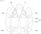
FIG. 3 is a view illustrating a shape made before the airbag cushion and the tether according to the present disclosure are deployed. -
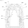
FIG. 4 is a view illustrating tear lines formed on a covering and illustrating the airbag cushion and the tether embedded in a seatback according to the present disclosure. -
FIG. 5 is a cross-sectional view taken along line A-A inFIG. 4 . -
FIG. 6 is a cross-sectional view taken along line B-B inFIG. 4 . - Hereinafter, embodiments disclosed in the present specification will be described in detail with reference to the accompanying drawings. The same or similar constituent elements are assigned with the same reference numerals regardless of reference numerals, and the repetitive description thereof will be omitted.
- The suffixes 'module', 'unit', 'part', and 'portion' used to describe constituent elements in the following description are used together or interchangeably in order to facilitate the description, but the suffixes themselves do not have distinguishable meanings or functions.
- In the description of the embodiments disclosed in the present specification, the specific descriptions of publicly known related technologies will be omitted when it is determined that the specific descriptions may obscure the subject matter of the embodiments disclosed in the present specification. In addition, it should be interpreted that the accompanying drawings are provided only to allow those skilled in the art to easily understand the embodiments disclosed in the present specification, and the technical spirit disclosed in the present specification is not limited by the accompanying drawings, and includes all alterations, equivalents, and alternatives that are included in the spirit and the technical scope of the present disclosure.
- The terms including ordinal numbers such as "first," "second," and the like may be used to describe various constituent elements, but the constituent elements are not limited by the terms. These terms are used only to distinguish one constituent element from another constituent element.
- When one constituent element is described as being "coupled" or "connected" to another constituent element, it should be understood that one constituent element can be coupled or connected directly to another constituent element, and an intervening constituent element can also be present between the constituent elements. When one constituent element is described as being "coupled directly to" or "connected directly to" another constituent element, it should be understood that no intervening constituent element is present between the constituent elements.
- Singular expressions include plural expressions unless clearly described as different meanings in the context.
- In the present specification, it should be understood the terms "comprises," "comprising," "includes," "including," "containing," "has," "having" or other variations thereof are inclusive and therefore specify the presence of stated features, integers, steps, operations, elements, components, or combinations thereof, but do not preclude the presence or addition of one or more other features, integers, steps, operations, elements, components, or combinations thereof.
- Hereinafter, exemplary embodiments of the present disclosure will be described in detail with reference to the accompanying drawings.
- With reference to
FIGS. 1 and2 , anairbag cushion 200 according to the present disclosure includes alateral chamber 200a configured to be deployed in a shape that covers a lateral side of a seat, and afront chamber 200b configured to be deployed in a shape that covers a front side of the seat. - The
lateral chamber 200a is deployed to be elongated in an upward/downward longitudinal direction while being deployed forward from a left or right side of aseatback 10. - The
lateral chamber 200a is deployed to a space between a passenger and a vehicle structure such as a door and a center console and protects the passenger's head, shoulder, chest, abdomen, and pelvis that are main parts of the lateral side of the passenger. - The
front chambers 200b are respectively connected to front ends of thelateral chambers 200a disposed at the left and right sides and configured to be deployed in shapes shape bent toward the front side of the passenger. - The
front chamber 200b is deployed to protect a region from the passenger's shoulder to the passenger's abdomen. - That is, at the left and right sides of the seat, the
lateral chambers 200a and thefront chambers 200b are deployed in shapes that entirely surround the passenger's two opposite sides and the passenger's front side. - Therefore, the airbag directly restrains the passenger in accordance with various positions of the seat and various postures of the passenger, thereby safely protecting the passenger while coping with various collision modes. Therefore, the airbag may be substituted for a seat belt as well as airbags disposed at the other portions, thereby greatly improving marketability.
- Meanwhile, according to the present disclosure, tethers 300, together with the
airbag cushions 200, are embedded in theseatback 10. Thetethers 300 are unfolded while cutting through theseatback 10 when the airbag is deployed, thereby regulating deployment shapes of theairbag cushions 200. - With reference to
FIGS. 1 to 4 , an airbag device of the present disclosure includes: afoam pad 100 embedded in theseatback 10; theairbag cushions 200 folded at lateral sides of thefoam pad 100 and configured to be deployed forward; acovering 400 shaped to cover thefoam pad 100 and configured to cover theseatback 10; and thetether 300 positioned between thefoam pad 100 and thecovering 400 and connected between theseatback 10 and theairbag cushion 200, thetether 300 being configured to be unfolded while cutting the covering 400 when theairbag cushion 200 is deployed. - Specifically, the
foam pad 100 is embedded in theseatback 10 and implements a shape of theseatback 10. - Further, the
airbag cushions 200 are folded at left and right positions of thefoam pad 100, and theairbag cushion 200 may be assembled to left andright seatback frames 11. - Further, the
seatback 10 is covered by the covering 400, such that theairbag cushions 200, together with thefoam pad 100, are covered by the covering 400. - Further, one end of the
tether 300 is fixed to theairbag cushion 200, and the other end of thetether 300 is fixed to an upper end of theseatback 10. - In particular, a middle portion of the
tether 300, which extends between theairbag cushion 200 and theseatback 10, is positioned between thefoam pad 100 and the covering 400. That is, thetether 300 is positioned on a rear surface of the covering 400, and thetether 300 passes through a part where thefoam pad 100 and the covering 400 overlap each other. - That is, when the
airbag cushion 200 is deployed, thetether 300 is unfolded while cutting only the covering 400, such that a relatively high force is not required to deploy thetether 300. Therefore, the deployment performance of thetether 300 may be improved, such that theairbag cushion 200 may be normally deployed. - Further, according to the present disclosure, a
slit 110, which has a shape opened forward, is formed in a boundary portion between theairbag cushion 200 and thefoam pad 100, and thetether 300 passes through theslit 110. - For example, as illustrated in
FIGS. 4 and5 , thetether 300 fixed to theairbag cushion 200 adjoins theslit 110, such that thetether 300 is positioned in a form accommodated in theslit 110. Further, thetether 300 having passed through theslit 110 is positioned between thefoam pad 100 and thecovering 400. - In this case, the
slit 110 may be formed in a groove shape opened forward, and a gap of theslit 110 in a width direction of theslit 110 may be formed to be at least larger than a thickness of thetether 300. - Therefore, the
tether 300 positioned in theslit 110 is unfolded while being easily extended to a front side of theslit 110 while theairbag cushion 200 is deployed, such that the deployment performance of thetether 300 is improved, and theairbag cushion 200 is more stably deployed. - Further, the
slit 110 may be formed in thefoam pad 100. - For example, the
slits 110 may be formed in a forward/rearward direction and disposed at the left and right sides of thefoam pad 100. Theslit 110 may be formed to an end of the rear surface of thefoam pad 100. However, theslit 110 may be formed only to a predetermined depth in thefoam pad 100 so that a thickness of thefoam pad 100 at the portion of theslit 110 is smaller than a thickness of thefoam pad 100 at the periphery, such that the function of theslit 110 may be implemented. - Further, according to the present disclosure, a
position regulation groove 120 is formed in a portion of thefoam pad 100 that faces the covering 400, such that thetether 300 may be positioned in theposition regulation groove 120. - With reference to
FIGS. 4 and6 , theposition regulation groove 120, which is recessed concavely, is formed in the portion of thefoam pad 100 that faces the covering 400 and allows thetether 300 to pass therethrough. - Therefore, the position of the
tether 300 is regulated between thefoam pad 100 and the covering 400, thereby improving assembling properties and workability of thetether 300. - In this case, the
position regulation groove 120 may be formed in thefoam pad 100 that adjoins theslit 110. - That is, the
position regulation groove 120 extends to a front end of theslit 110, thetether 300 fixed to theairbag cushion 200 enters theposition regulation groove 120 immediately after passing through theslit 110. - Therefore, the regulation of the position of the
tether 300 is more easily and conveniently performed, such that assembling properties and workability of thetether 300 are further improved. - Meanwhile, in the present disclosure, the
tethers 300 may includeupper tethers 300a extending upwardly from upper ends of the airbag cushions 200 along a rim of theseatback 10 and connected to an upper end of theseatback frame 11. - With reference to
FIGS. 3 and4 , one end of theupper tether 300a is fixed to the upper end of theairbag cushion 200, and the other end of theupper tether 300a extends to the upper end of theseatback 10 and is fixed to the upper end of theseatback frame 11. - Specifically, one end of the
upper tether 300a is fixed to an upper end of thefront chamber 200b and fixed to an inner surface of thelateral chamber 200a extending to the upper end of thefront chamber 200b, and the other end of theupper tether 300a is fixed at one point on theseatback frame 11, such that theupper tether 300a is deployed in a triangular surface shape. - Therefore, the
upper tether 300a extends from the upper end of theseatback 10, passes over the passenger's shoulder, and is fixed to theairbag cushion 200 that covers the passenger's front and lateral sides, thereby regulating a deployment shape of an upper end of theairbag cushion 200. - Further, the
upper tether 300a may be connected to the upper end of theseatback 10 positioned to be relatively distant from theairbag cushion 200. - For example, the
upper tether 300a fixed to the upper end of theleft airbag cushion 200 is fixed to a right side of the upper end of theseatback 10, and theupper tether 300a fixed to the upper end of theright airbag cushion 200 is fixed to a left side of the upper end of theseatback 10. - Therefore, a fixing point of the
upper tether 300a fixed to theseatback 10 is distant from a fixing point of theupper tether 300a fixed to theairbag cushion 200, such that theairbag cushion 200 may be pulled by theupper tether 300a with a higher force, which more assuredly regulates the outward spread of the airbag cushions 200. - Further, a
tether tear line 420 is sewn to the covering 400 along thetether 300, such that thetether 300 may be unfolded while cutting thetether tear line 420. - In this case, the
tether tear line 420 may be formed by weakening a sewn line formed at the upper end of theseatback 10. - With reference to
FIGS. 3 and4 ,cushion tear lines 410 are formed in an upward/downward longitudinal direction at the left and right sides of theseatback 10, such that theairbag cushion 200 is deployed forward while cutting thecushion tear line 410. - Further, the
tether tear line 420 extends to upper portions of thecushion tear lines 410, such that thetether 300 is unfolded while cutting thetether tear line 420. - In this case, the
tether tear line 420 is formed while passing through the portion facing theslit 110. - Therefore, the
airbag cushion 200 is deployed forward while cutting thecushion tear lines 410 of the covering 400 and thefoam pad 100, and theupper tether 300a is deployed forward while cutting thetether tear line 420 of the covering 400, such that the airbag is normally and quickly deployed. - Meanwhile, in the present disclosure, the
tethers 300 may includelower tethers 300b extending downwardly from lower ends of theairbag cushion 200 along the rim of theseatback 10 and connected to a lower end of theseatback frame 11. - Specifically, one end of the
lower tether 300b is fixed to a lower end of thefront chamber 200b and fixed to an inner surface of thelateral chamber 200a extending to the lower end of thefront chamber 200b, and the other end of thelower tether 300b is fixed at one left or right point on theseatback frame 11, such that thelower tether 300b is deployed in a triangular surface shape. - Therefore, the
lower tether 300b extends from the lower end of theseatback 10, passes over the passenger's thigh, and is fixed to theairbag cushion 200 that covers the passenger's front and lateral sides, thereby stably regulating a deployment shape of a lower end of theairbag cushion 200. - As described above, according to the present disclosure, the middle portion of the
tether 300, which extends between theairbag cushion 200 and theseatback 10, is positioned between thefoam pad 100 and thecovering 400. - Therefore, when the
airbag cushion 200 is deployed, thetether 300 is unfolded while cutting only the covering 400, such that a relatively high force is not required to deploy thetether 300. Therefore, the deployment performance of thetether 300 is improved, and theairbag cushion 200 is prevented from being abnormally deployed. - While the present disclosure has been described with reference to the specific examples, it is apparent to those skilled in the art that various modifications and alterations may be made within the technical spirit of the present disclosure, and these modifications and alterations belong to the appended claims.
Claims (10)
- An airbag device comprising:a foam pad embedded in a seatback;an airbag cushion folded at a lateral side of the foam pad and configured to be deployed forward;a covering shaped to cover the foam pad and configured to cover the seatback; anda tether positioned between the foam pad and the covering and connected between the seatback and the airbag cushion, the tether being configured to unfold while the covering tears when the airbag cushion is deployed.
- The airbag device of claim 1, wherein a slit, which has a shape opened forward, is formed in a boundary portion between the airbag cushion and the foam pad, and
wherein the tether passes through the slit when the tether unfolds. - The airbag device of claim 1 or 2, wherein the slit is formed in the foam pad.
- The airbag device of claim 2 or 3, wherein a position regulation groove is formed in a portion of the foam pad that faces the covering, and
wherein the tether is positioned in the position regulation groove when the tether is folded. - The airbag device of claim 4, wherein the position regulation groove is formed in a portion of the foam pad that adjoins the slit.
- The airbag device of any one of claims 1 to 5, wherein the tether comprises an upper tether extending upwardly from an upper end of the airbag cushion along a rim of the seatback, the upper tether being connected to an upper end of a seatback frame.
- The airbag device of claim 6, wherein the upper tether is connected to the upper end of the seatback frame at a position that is spaced apart from the airbag cushion.
- The airbag device of any one of claims 1 to 7, wherein a tether tear line is sewn into the covering along the tether, and
wherein the tether unfolds while the tether tear line tears when the airbag cushion is deployed. - The airbag device of any one of claims 6 to 8, wherein the tether comprises a lower tether extending downwardly from a lower end of the airbag cushion along the rim of the seatback and connected to a lower end of the seatback frame.
- The airbag device of claim 9, wherein the airbag cushion includes (i) a lateral chamber shaped to cover a lateral side of a seat when the airbag cushion deploys, and (ii) a front chamber shaped to cover a front side of the seat when the airbag cushion deploys,wherein the upper tether is connected to an upper end of the front chamber and to an inner surface of the lateral chamber extending to an upper end of the front chamber, andwherein the lower tether is connected to a lower end of the front chamber and to the inner surface of the lateral chamber extending to a lower end of the front chamber.
Applications Claiming Priority (1)
| Application Number | Priority Date | Filing Date | Title |
|---|---|---|---|
| KR1020230033419A KR20240139417A (en) | 2023-03-14 | 2023-03-14 | Airbag device |
Publications (2)
| Publication Number | Publication Date |
|---|---|
| EP4438417A1 true EP4438417A1 (en) | 2024-10-02 |
| EP4438417B1 EP4438417B1 (en) | 2025-10-15 |
Family
ID=87473811
Family Applications (1)
| Application Number | Title | Priority Date | Filing Date |
|---|---|---|---|
| EP23187475.1A Active EP4438417B1 (en) | 2023-03-14 | 2023-07-25 | Airbag device |
Country Status (4)
| Country | Link |
|---|---|
| US (1) | US12090948B1 (en) |
| EP (1) | EP4438417B1 (en) |
| KR (1) | KR20240139417A (en) |
| CN (1) | CN118665385A (en) |
Families Citing this family (2)
| Publication number | Priority date | Publication date | Assignee | Title |
|---|---|---|---|---|
| KR20260001949A (en) * | 2024-06-28 | 2026-01-06 | 현대모비스 주식회사 | Airbag cushion and method for folding airbag cushion |
| KR20260062716A (en) * | 2024-10-29 | 2026-05-07 | 현대모비스 주식회사 | Airbag apparatus |
Citations (4)
| Publication number | Priority date | Publication date | Assignee | Title |
|---|---|---|---|---|
| US20050156412A1 (en) * | 2004-01-16 | 2005-07-21 | Lear Corporation | Air bag deployment arrangement |
| KR20120118233A (en) * | 2011-04-18 | 2012-10-26 | 현대모비스 주식회사 | A side airbag apparatus |
| KR20120126647A (en) * | 2011-05-12 | 2012-11-21 | 현대모비스 주식회사 | A side airbag apparatus |
| DE202021104527U1 (en) * | 2020-08-25 | 2021-09-03 | Hyundai Mobis Co., Ltd. | Side airbag for a vehicle |
Family Cites Families (11)
| Publication number | Priority date | Publication date | Assignee | Title |
|---|---|---|---|---|
| JPS6432547U (en) | 1987-08-21 | 1989-03-01 | ||
| DE102010045969A1 (en) * | 2010-09-18 | 2012-03-22 | Gm Global Technology Operations Llc (N.D.Ges.D. Staates Delaware) | Vehicle seat with an airbag |
| WO2012117561A1 (en) | 2011-03-03 | 2012-09-07 | トヨタ自動車株式会社 | Side airbag device for automobile |
| JP5690289B2 (en) * | 2012-01-25 | 2015-03-25 | 日本発條株式会社 | Vehicle seat and sewing method |
| JP6129807B2 (en) * | 2014-10-28 | 2017-05-17 | トヨタ紡織株式会社 | Vehicle seat |
| DE102015003790A1 (en) * | 2015-03-23 | 2016-09-29 | Isringhausen Gmbh & Co. Kg | Structure for receiving an inflatable airbag and vehicle seat with such a structure |
| JP6432547B2 (en) | 2016-03-02 | 2018-12-05 | トヨタ自動車株式会社 | Side airbag device for vehicle |
| JP6332308B2 (en) * | 2016-03-10 | 2018-05-30 | トヨタ自動車株式会社 | Vehicle seat with side airbag device |
| JP6822921B2 (en) | 2017-08-14 | 2021-01-27 | トヨタ自動車株式会社 | Pedestrian protection airbag |
| JP2019084945A (en) | 2017-11-07 | 2019-06-06 | Joyson Safety Systems Japan株式会社 | Knee airbag and knee airbag device |
| EP3584122B1 (en) * | 2018-01-26 | 2021-11-17 | Autoliv Development AB | Side airbag device |
-
2023
- 2023-03-14 KR KR1020230033419A patent/KR20240139417A/en active Pending
- 2023-07-25 EP EP23187475.1A patent/EP4438417B1/en active Active
- 2023-08-01 US US18/363,053 patent/US12090948B1/en active Active
- 2023-08-18 CN CN202311048465.XA patent/CN118665385A/en active Pending
Patent Citations (4)
| Publication number | Priority date | Publication date | Assignee | Title |
|---|---|---|---|---|
| US20050156412A1 (en) * | 2004-01-16 | 2005-07-21 | Lear Corporation | Air bag deployment arrangement |
| KR20120118233A (en) * | 2011-04-18 | 2012-10-26 | 현대모비스 주식회사 | A side airbag apparatus |
| KR20120126647A (en) * | 2011-05-12 | 2012-11-21 | 현대모비스 주식회사 | A side airbag apparatus |
| DE202021104527U1 (en) * | 2020-08-25 | 2021-09-03 | Hyundai Mobis Co., Ltd. | Side airbag for a vehicle |
Also Published As
| Publication number | Publication date |
|---|---|
| KR20240139417A (en) | 2024-09-23 |
| US12090948B1 (en) | 2024-09-17 |
| EP4438417B1 (en) | 2025-10-15 |
| CN118665385A (en) | 2024-09-20 |
| US20240308461A1 (en) | 2024-09-19 |
Similar Documents
| Publication | Publication Date | Title |
|---|---|---|
| JP4235975B2 (en) | Airbag device and airbag manufacturing method | |
| EP3772438B1 (en) | Airbag device | |
| US8899619B2 (en) | Vehicle seat | |
| CN114174128B (en) | air bag device | |
| US7712781B2 (en) | Protective cushion wrap with slip feature | |
| EP4438417B1 (en) | Airbag device | |
| EP3778311B1 (en) | Side airbag device and vehicle seat | |
| EP3141437A1 (en) | Far side airbag device and vehicle seat | |
| CN215706180U (en) | Side airbag for vehicle | |
| US5630615A (en) | Side impact supplemental inflation restraint | |
| EP3778310B1 (en) | Side airbag device | |
| US11383669B2 (en) | Airbag cushions with pass-through chambers and related systems | |
| JP2008201172A (en) | Side airbag device. | |
| JP7093811B2 (en) | Airbag device | |
| US11945394B2 (en) | Curtain airbag | |
| US12109964B2 (en) | Airbag device | |
| WO2019244493A1 (en) | Side airbag device and vehicle seat provided therewith | |
| EP3744579B1 (en) | Side air bag device and vehicle seat with same | |
| JP7169258B2 (en) | side airbag device | |
| JP6380064B2 (en) | Side airbag device for vehicle | |
| JP4355153B2 (en) | Vehicle airbag device | |
| US11091116B2 (en) | Airbag device | |
| WO2023282019A1 (en) | Airbag device | |
| EP1650087B1 (en) | Airbag device | |
| JP2000142290A (en) | Vehicle airbag |
Legal Events
| Date | Code | Title | Description |
|---|---|---|---|
| PUAI | Public reference made under article 153(3) epc to a published international application that has entered the european phase |
Free format text: ORIGINAL CODE: 0009012 |
|
| STAA | Information on the status of an ep patent application or granted ep patent |
Free format text: STATUS: THE APPLICATION HAS BEEN PUBLISHED |
|
| AK | Designated contracting states |
Kind code of ref document: A1 Designated state(s): AL AT BE BG CH CY CZ DE DK EE ES FI FR GB GR HR HU IE IS IT LI LT LU LV MC ME MK MT NL NO PL PT RO RS SE SI SK SM TR |
|
| STAA | Information on the status of an ep patent application or granted ep patent |
Free format text: STATUS: REQUEST FOR EXAMINATION WAS MADE |
|
| 17P | Request for examination filed |
Effective date: 20250321 |
|
| RIC1 | Information provided on ipc code assigned before grant |
Ipc: B60R 21/2338 20110101ALI20250424BHEP Ipc: B60R 21/207 20060101AFI20250424BHEP |
|
| GRAP | Despatch of communication of intention to grant a patent |
Free format text: ORIGINAL CODE: EPIDOSNIGR1 |
|
| STAA | Information on the status of an ep patent application or granted ep patent |
Free format text: STATUS: GRANT OF PATENT IS INTENDED |
|
| INTG | Intention to grant announced |
Effective date: 20250606 |
|
| GRAS | Grant fee paid |
Free format text: ORIGINAL CODE: EPIDOSNIGR3 |
|
| GRAA | (expected) grant |
Free format text: ORIGINAL CODE: 0009210 |
|
| STAA | Information on the status of an ep patent application or granted ep patent |
Free format text: STATUS: THE PATENT HAS BEEN GRANTED |
|
| AK | Designated contracting states |
Kind code of ref document: B1 Designated state(s): AL AT BE BG CH CY CZ DE DK EE ES FI FR GB GR HR HU IE IS IT LI LT LU LV MC ME MK MT NL NO PL PT RO RS SE SI SK SM TR |
|
| P01 | Opt-out of the competence of the unified patent court (upc) registered |
Free format text: CASE NUMBER: UPC_APP_6110_4438417/2025 Effective date: 20250905 |
|
| REG | Reference to a national code |
Ref country code: GB Ref legal event code: FG4D Ref country code: CH Ref legal event code: F10 Free format text: ST27 STATUS EVENT CODE: U-0-0-F10-F00 (AS PROVIDED BY THE NATIONAL OFFICE) Effective date: 20251015 |
|
| REG | Reference to a national code |
Ref country code: DE Ref legal event code: R096 Ref document number: 602023007485 Country of ref document: DE |
|
| REG | Reference to a national code |
Ref country code: IE Ref legal event code: FG4D |
|
| REG | Reference to a national code |
Ref country code: NL Ref legal event code: MP Effective date: 20251015 |
|
| REG | Reference to a national code |
Ref country code: AT Ref legal event code: MK05 Ref document number: 1846698 Country of ref document: AT Kind code of ref document: T Effective date: 20251015 |
|
| PG25 | Lapsed in a contracting state [announced via postgrant information from national office to epo] |
Ref country code: NL Free format text: LAPSE BECAUSE OF FAILURE TO SUBMIT A TRANSLATION OF THE DESCRIPTION OR TO PAY THE FEE WITHIN THE PRESCRIBED TIME-LIMIT Effective date: 20251015 |
|
| PG25 | Lapsed in a contracting state [announced via postgrant information from national office to epo] |
Ref country code: ES Free format text: LAPSE BECAUSE OF FAILURE TO SUBMIT A TRANSLATION OF THE DESCRIPTION OR TO PAY THE FEE WITHIN THE PRESCRIBED TIME-LIMIT Effective date: 20251015 |
|
| REG | Reference to a national code |
Ref country code: LT Ref legal event code: MG9D |
|
| PG25 | Lapsed in a contracting state [announced via postgrant information from national office to epo] |
Ref country code: NO Free format text: LAPSE BECAUSE OF FAILURE TO SUBMIT A TRANSLATION OF THE DESCRIPTION OR TO PAY THE FEE WITHIN THE PRESCRIBED TIME-LIMIT Effective date: 20260115 |
|
| PG25 | Lapsed in a contracting state [announced via postgrant information from national office to epo] |
Ref country code: FI Free format text: LAPSE BECAUSE OF FAILURE TO SUBMIT A TRANSLATION OF THE DESCRIPTION OR TO PAY THE FEE WITHIN THE PRESCRIBED TIME-LIMIT Effective date: 20251015 Ref country code: HR Free format text: LAPSE BECAUSE OF FAILURE TO SUBMIT A TRANSLATION OF THE DESCRIPTION OR TO PAY THE FEE WITHIN THE PRESCRIBED TIME-LIMIT Effective date: 20251015 Ref country code: AT Free format text: LAPSE BECAUSE OF FAILURE TO SUBMIT A TRANSLATION OF THE DESCRIPTION OR TO PAY THE FEE WITHIN THE PRESCRIBED TIME-LIMIT Effective date: 20251015 |
|
| PG25 | Lapsed in a contracting state [announced via postgrant information from national office to epo] |
Ref country code: RS Free format text: LAPSE BECAUSE OF FAILURE TO SUBMIT A TRANSLATION OF THE DESCRIPTION OR TO PAY THE FEE WITHIN THE PRESCRIBED TIME-LIMIT Effective date: 20260115 |
|
| PG25 | Lapsed in a contracting state [announced via postgrant information from national office to epo] |
Ref country code: IS Free format text: LAPSE BECAUSE OF FAILURE TO SUBMIT A TRANSLATION OF THE DESCRIPTION OR TO PAY THE FEE WITHIN THE PRESCRIBED TIME-LIMIT Effective date: 20260215 |
|
| PG25 | Lapsed in a contracting state [announced via postgrant information from national office to epo] |
Ref country code: PT Free format text: LAPSE BECAUSE OF FAILURE TO SUBMIT A TRANSLATION OF THE DESCRIPTION OR TO PAY THE FEE WITHIN THE PRESCRIBED TIME-LIMIT Effective date: 20260216 |
|
| PG25 | Lapsed in a contracting state [announced via postgrant information from national office to epo] |
Ref country code: PL Free format text: LAPSE BECAUSE OF FAILURE TO SUBMIT A TRANSLATION OF THE DESCRIPTION OR TO PAY THE FEE WITHIN THE PRESCRIBED TIME-LIMIT Effective date: 20251015 |
|
| PG25 | Lapsed in a contracting state [announced via postgrant information from national office to epo] |
Ref country code: LV Free format text: LAPSE BECAUSE OF FAILURE TO SUBMIT A TRANSLATION OF THE DESCRIPTION OR TO PAY THE FEE WITHIN THE PRESCRIBED TIME-LIMIT Effective date: 20251015 |
|
| PG25 | Lapsed in a contracting state [announced via postgrant information from national office to epo] |
Ref country code: BG Free format text: LAPSE BECAUSE OF FAILURE TO SUBMIT A TRANSLATION OF THE DESCRIPTION OR TO PAY THE FEE WITHIN THE PRESCRIBED TIME-LIMIT Effective date: 20251015 |
|
| PG25 | Lapsed in a contracting state [announced via postgrant information from national office to epo] |
Ref country code: LT Free format text: LAPSE BECAUSE OF FAILURE TO SUBMIT A TRANSLATION OF THE DESCRIPTION OR TO PAY THE FEE WITHIN THE PRESCRIBED TIME-LIMIT Effective date: 20251015 |
|
| PG25 | Lapsed in a contracting state [announced via postgrant information from national office to epo] |
Ref country code: SM Free format text: LAPSE BECAUSE OF FAILURE TO SUBMIT A TRANSLATION OF THE DESCRIPTION OR TO PAY THE FEE WITHIN THE PRESCRIBED TIME-LIMIT Effective date: 20251015 |
|
| PG25 | Lapsed in a contracting state [announced via postgrant information from national office to epo] |
Ref country code: DK Free format text: LAPSE BECAUSE OF FAILURE TO SUBMIT A TRANSLATION OF THE DESCRIPTION OR TO PAY THE FEE WITHIN THE PRESCRIBED TIME-LIMIT Effective date: 20251015 |
|
| PG25 | Lapsed in a contracting state [announced via postgrant information from national office to epo] |
Ref country code: IT Free format text: LAPSE BECAUSE OF FAILURE TO SUBMIT A TRANSLATION OF THE DESCRIPTION OR TO PAY THE FEE WITHIN THE PRESCRIBED TIME-LIMIT Effective date: 20251015 |
|
| PG25 | Lapsed in a contracting state [announced via postgrant information from national office to epo] |
Ref country code: EE Free format text: LAPSE BECAUSE OF FAILURE TO SUBMIT A TRANSLATION OF THE DESCRIPTION OR TO PAY THE FEE WITHIN THE PRESCRIBED TIME-LIMIT Effective date: 20251015 |
|
| PG25 | Lapsed in a contracting state [announced via postgrant information from national office to epo] |
Ref country code: CZ Free format text: LAPSE BECAUSE OF FAILURE TO SUBMIT A TRANSLATION OF THE DESCRIPTION OR TO PAY THE FEE WITHIN THE PRESCRIBED TIME-LIMIT Effective date: 20251015 |
|
| PGFP | Annual fee paid to national office [announced via postgrant information from national office to epo] |
Ref country code: FR Payment date: 20260527 Year of fee payment: 4 |
|
| PG25 | Lapsed in a contracting state [announced via postgrant information from national office to epo] |
Ref country code: SK Free format text: LAPSE BECAUSE OF FAILURE TO SUBMIT A TRANSLATION OF THE DESCRIPTION OR TO PAY THE FEE WITHIN THE PRESCRIBED TIME-LIMIT Effective date: 20251015 |
|
| PG25 | Lapsed in a contracting state [announced via postgrant information from national office to epo] |
Ref country code: SE Free format text: LAPSE BECAUSE OF FAILURE TO SUBMIT A TRANSLATION OF THE DESCRIPTION OR TO PAY THE FEE WITHIN THE PRESCRIBED TIME-LIMIT Effective date: 20251015 |