EP4438224A1 - Apparatus and process for working on a part - Google Patents
Apparatus and process for working on a part Download PDFInfo
- Publication number
- EP4438224A1 EP4438224A1 EP24163967.3A EP24163967A EP4438224A1 EP 4438224 A1 EP4438224 A1 EP 4438224A1 EP 24163967 A EP24163967 A EP 24163967A EP 4438224 A1 EP4438224 A1 EP 4438224A1
- Authority
- EP
- European Patent Office
- Prior art keywords
- arch
- track
- end effector
- arches
- fixed
- Prior art date
- Legal status (The legal status is an assumption and is not a legal conclusion. Google has not performed a legal analysis and makes no representation as to the accuracy of the status listed.)
- Pending
Links
Images



Classifications
-
- B—PERFORMING OPERATIONS; TRANSPORTING
- B23—MACHINE TOOLS; METAL-WORKING NOT OTHERWISE PROVIDED FOR
- B23Q—DETAILS, COMPONENTS, OR ACCESSORIES FOR MACHINE TOOLS, e.g. ARRANGEMENTS FOR COPYING OR CONTROLLING; MACHINE TOOLS IN GENERAL CHARACTERISED BY THE CONSTRUCTION OF PARTICULAR DETAILS OR COMPONENTS; COMBINATIONS OR ASSOCIATIONS OF METAL-WORKING MACHINES, NOT DIRECTED TO A PARTICULAR RESULT
- B23Q1/00—Members which are comprised in the general build-up of a form of machine, particularly relatively large fixed members
- B23Q1/01—Frames, beds, pillars or like members; Arrangement of ways
- B23Q1/012—Portals
-
- B—PERFORMING OPERATIONS; TRANSPORTING
- B25—HAND TOOLS; PORTABLE POWER-DRIVEN TOOLS; MANIPULATORS
- B25J—MANIPULATORS; CHAMBERS PROVIDED WITH MANIPULATION DEVICES
- B25J5/00—Manipulators mounted on wheels or on carriages
- B25J5/02—Manipulators mounted on wheels or on carriages travelling along a guideway
- B25J5/04—Manipulators mounted on wheels or on carriages travelling along a guideway wherein the guideway is also moved, e.g. travelling crane bridge type
-
- B—PERFORMING OPERATIONS; TRANSPORTING
- B23—MACHINE TOOLS; METAL-WORKING NOT OTHERWISE PROVIDED FOR
- B23P—METAL-WORKING NOT OTHERWISE PROVIDED FOR; COMBINED OPERATIONS; UNIVERSAL MACHINE TOOLS
- B23P23/00—Machines or arrangements of machines for performing specified combinations of different metal-working operations not covered by a single other subclass
-
- B—PERFORMING OPERATIONS; TRANSPORTING
- B23—MACHINE TOOLS; METAL-WORKING NOT OTHERWISE PROVIDED FOR
- B23Q—DETAILS, COMPONENTS, OR ACCESSORIES FOR MACHINE TOOLS, e.g. ARRANGEMENTS FOR COPYING OR CONTROLLING; MACHINE TOOLS IN GENERAL CHARACTERISED BY THE CONSTRUCTION OF PARTICULAR DETAILS OR COMPONENTS; COMBINATIONS OR ASSOCIATIONS OF METAL-WORKING MACHINES, NOT DIRECTED TO A PARTICULAR RESULT
- B23Q1/00—Members which are comprised in the general build-up of a form of machine, particularly relatively large fixed members
- B23Q1/25—Movable or adjustable work or tool supports
-
- B—PERFORMING OPERATIONS; TRANSPORTING
- B23—MACHINE TOOLS; METAL-WORKING NOT OTHERWISE PROVIDED FOR
- B23Q—DETAILS, COMPONENTS, OR ACCESSORIES FOR MACHINE TOOLS, e.g. ARRANGEMENTS FOR COPYING OR CONTROLLING; MACHINE TOOLS IN GENERAL CHARACTERISED BY THE CONSTRUCTION OF PARTICULAR DETAILS OR COMPONENTS; COMBINATIONS OR ASSOCIATIONS OF METAL-WORKING MACHINES, NOT DIRECTED TO A PARTICULAR RESULT
- B23Q39/00—Metal-working machines incorporating a plurality of sub-assemblies, each capable of performing a metal-working operation
-
- B—PERFORMING OPERATIONS; TRANSPORTING
- B23—MACHINE TOOLS; METAL-WORKING NOT OTHERWISE PROVIDED FOR
- B23Q—DETAILS, COMPONENTS, OR ACCESSORIES FOR MACHINE TOOLS, e.g. ARRANGEMENTS FOR COPYING OR CONTROLLING; MACHINE TOOLS IN GENERAL CHARACTERISED BY THE CONSTRUCTION OF PARTICULAR DETAILS OR COMPONENTS; COMBINATIONS OR ASSOCIATIONS OF METAL-WORKING MACHINES, NOT DIRECTED TO A PARTICULAR RESULT
- B23Q7/00—Arrangements for handling work specially combined with or arranged in, or specially adapted for use in connection with, machine tools, e.g. for conveying, loading, positioning, discharging, sorting
- B23Q7/001—Lateral transport of long workpieces
-
- B—PERFORMING OPERATIONS; TRANSPORTING
- B64—AIRCRAFT; AVIATION; COSMONAUTICS
- B64F—GROUND OR AIRCRAFT-CARRIER-DECK INSTALLATIONS SPECIALLY ADAPTED FOR USE IN CONNECTION WITH AIRCRAFT; DESIGNING, MANUFACTURING, ASSEMBLING, CLEANING, MAINTAINING OR REPAIRING AIRCRAFT, NOT OTHERWISE PROVIDED FOR; HANDLING, TRANSPORTING, TESTING OR INSPECTING AIRCRAFT COMPONENTS, NOT OTHERWISE PROVIDED FOR
- B64F5/00—Designing, manufacturing, assembling, cleaning, maintaining or repairing aircraft, not otherwise provided for; Handling, transporting, testing or inspecting aircraft components, not otherwise provided for
- B64F5/10—Manufacturing or assembling aircraft, e.g. jigs therefor
-
- B—PERFORMING OPERATIONS; TRANSPORTING
- B23—MACHINE TOOLS; METAL-WORKING NOT OTHERWISE PROVIDED FOR
- B23P—METAL-WORKING NOT OTHERWISE PROVIDED FOR; COMBINED OPERATIONS; UNIVERSAL MACHINE TOOLS
- B23P2700/00—Indexing scheme relating to the articles being treated, e.g. manufactured, repaired, assembled, connected or other operations covered in the subgroups
- B23P2700/01—Aircraft parts
-
- B—PERFORMING OPERATIONS; TRANSPORTING
- B23—MACHINE TOOLS; METAL-WORKING NOT OTHERWISE PROVIDED FOR
- B23Q—DETAILS, COMPONENTS, OR ACCESSORIES FOR MACHINE TOOLS, e.g. ARRANGEMENTS FOR COPYING OR CONTROLLING; MACHINE TOOLS IN GENERAL CHARACTERISED BY THE CONSTRUCTION OF PARTICULAR DETAILS OR COMPONENTS; COMBINATIONS OR ASSOCIATIONS OF METAL-WORKING MACHINES, NOT DIRECTED TO A PARTICULAR RESULT
- B23Q2210/00—Machine tools incorporating a specific component
- B23Q2210/006—Curved guiding rails
Definitions
- This invention relates generally to processes and devices for working on parts, and more particularly to processes and devices that position end effectors relative to the part to perform the operations.
- a device which uses two parallel flexible rails which are secured on the structure to be machined.
- the rails are secured on the structure by suction.
- An end effector for example a drill, is moved along the two rails. While presumably effective for its intended purpose, a device of this type is complicated and time consuming to implement.
- the width between the two rails and the surface which can be reached by the machining tool are limited.
- a new apparatus for performing operations on a part, and in particular on the fuselage of an aircraft has been invented.
- the device utilizes a track with fixed rails on opposites sides of the part.
- One or more end effectors are mounted on arched beams, or aches, which extend between the fixed rails and which can moved to a desired longitudinal location.
- the arched beams are upper arch beams passing over the upper portion of the part. This allows the arch beams to move unimpeded by supports or other structures that are located below the part and which support the part.
- One more lower arches may be positioned at specific longitudinal locations.
- the upper arch can be moved to the corresponding location of the lower arch and, once the arches are aligned, the end effector can move from the upper arch to the lower arch to perform operations on the lower portion of the part. Once completed, the end effector may move back to the first, or upper arch.
- the present invention may be characterized, in at least one aspect, as providing an apparatus for performing an operation on a part.
- the apparatus may include a track extending in direction parallel with a longitudinal axis of the part, a first arch mounted to the track, the first arch configured to move along the track to a longitudinal position, an end effector associated with the first arch, the end effector configured to move circumferentially around the longitudinal axis of the part; and, a means for moving the first arch, the means for moving mounted to as to move with the arch.
- Each arch may be formed from two parallel arches.
- the end effector may be mounted on a platform that extends between the two parallel arches of the first arch.
- the track may include two rails located on opposite sides of the part.
- the arch may extend between the two rails of the track.
- the apparatus may further include a second arch mounted to the track in a fixed longitudinal position.
- the end effector is configured to move from the first arch to the second arch when the first arch is positioned at the fixed longitudinal position.
- the second arch and the first arch together may form a complete circle around the part.
- the second arch and the first arch together may form less than a complete circle around the part.
- the first arch may include an extension having an engagement surface
- the second arch may include a latch an engagement surface configured complementarily to the engagement surface of the extension.
- the engagement surface of the extension may be a T-shape.
- the extension may be configured to be moved so as to allow the engagement surface of the extension to engage with the engagement surface of the latch.
- One of the first arch and the second arch may include an indexing feature configured to position the first and second arches together.
- the indexing feature may be a protrusion which may have a slanted surface.
- the apparatus may further include a third arch mounted to the track in a fixed longitudinal position.
- the end effector may be configured to move from the first arch to the third arch when the first arch is positioned at the fixed longitudinal position of the third arch.
- the second arch and the first arch together may form a complete circle around the part, and the third arch and the first arch together may form less than a complete circle around the part.
- the first arch may be an upper arch and the second arch may be a lower arch.
- the device may include a second upper arch.
- the present invention may also be generally characterized as providing a process for performing an operation on a part by: moving a first arch along a track to a desired longitudinal position, the track extending in a direction parallel with a longitudinal axis of the part, wherein the desired position coincides with a second arch fixed longitudinally relative to the desired longitudinal position; and, moving an end effector circumferentially around the longitudinal axis of the part from the first arch to the second arch.
- the process may include engaging an extension on the first arch with a latch on the second arch.
- one of the first arch or the second arch may include a protrusion configured to align the first arch with the second arch.
- an apparatus For performing operations on a part, an apparatus according to the present disclosure utilizes arches extending between fixed beams. Some of the arms are moveable, longitudinally, allowing end effectors to be positioned at a desired location. Additionally, arches are provided in fixed positions. When it is desired to perform operations using the fixed arches, a movable arch is positioned at the fixed arch, and brought into engagement therewith. This allows the end effector to move to the fixed arch. Compared with other movement systems, the present movement system allows for fixed rails to be used that are not attached to the part. Additionally, it avoids the supports that hold up the part.
- an apparatus 10 for performing operations on a part such as an aircraft fuselage, includes a track 12 extending in direction parallel with a longitudinal axis A1 of the part.
- the track 12 preferably includes two rails 14 on opposite sides of the longitudinal axis A1.
- the rails 14, and thus the track 12, are fixed to a permanent support supporting structure.
- permanent it is meant that the rails 14 are not affixed, attached, otherwise supported by the part.
- One or more movable arched beams, or arches, 16 are mounted to the track 12, and extend between the rails 14 by a means 17 for moving the arch 16.
- the means 17 for moving the arch may be a motor having a gear which engages with a track 12. As the motor turns the gear, the arch 16 may to move along the longitudinal axis A1. The direction of movement will depend on the direction of rotation of the gear.
- the motor means 17 may be mounted to platform 19 configured to be moved with the arch 16 and which may be used to support controllers, power sources, and other components associated with the apparatus 10.
- the movable arches 16 are configured to move along the track 12 and be positioned in a desired longitudinal location at which an end effector 18 is able to perform the operation on the part.
- the end effector 18 may be configured to perform an operation, like drilling, or riveting.
- the end effectors 18 could be sprayers, for painting or coating, or distance sensors for measuring.
- the arches 16 are provided in pairs with supports 20 extending therebetween.
- the end effector 18 may be mounted to a platform 22 or trolley that extends between the arches 16 in a particular pair. This may allow the end effector 18 to have additional longitudinal movement.
- the arches 16 include geared tracks 24 that allow the end effector 18 to move circumferentially around the longitudinal axis A1 (i.e., along the arch 16).
- the end effector 18, thanks to the longitudinal movement of the arch 16 may obtain the desired longitudinal position for performing the operation.
- the end effector 18 may also obtain the desired circumferential position based on moving along the arch 16.
- the end effector 18 may also have a radial movement, for example as part of the end effector 18 itself may extend (drill extending) or the end effector 18 may be mounted to an arm that may allow movement in the radial direction.
- the movable arches 16 are upper arches, allowing them to move freely along the longitudinal axis A1 without regard to supports and other equipment or devices located below the part.
- the end effector 18 may perform the operation on the underside of the part.
- fixed arches 26, 28 may be provided at specific locations. As will be described below, there may be some movement associated with these "fixed” arches 26, 28, but the longitudinal positioning of these arches 26, 28 does not change. Hence, they are deemed to be "fixed” arches 26, 28.
- the location of the fixed arches can be determined.
- the end effector 18 moves from the moveable arch 16 to the fixed arch 26, 28.
- the fixed arch 26 and the movable arch 16 may form a complete circle.
- the fixed arch 28 may only form part of a circle with the movable arch 16. This is particularly useful when the end effector 18 only needs to go a small distance circumferentially lower than the movable arch 16 allows.
- the movable arch 16 may include an extension 30 having an engagement surface, for example a T-shape 32.
- the extension 30 may be movable with for example a piston 34.
- the fixed arch 26, 28 may include a latch 36 having an engagement surface, such as an orifice 38, configured complementarily to the engagement surface of the extension 30.
- the piston 34 may being extending, resulting in the extension 30 moving towards the fixed arch 26, 28.
- the movable arch 18 may be moved longitudinally, so that the T-shape 32 of the extension 30 slides into the orifice 38 of the latch 36. Once engaged as such, the piston 34 can be retracted. The retraction of the piston 34 will cause the fixed arch 26, 28 to be pulled upward towards the movable arch 16.
- one of the arches 16, 26, 28 may include an indexing feature 40 which will guide the fixed arch 26, 28, to the appropriate position.
- the indexing feature 40 may be a protrusion 42 with one or more slanted surfaces 44 that is configured to be received in a correspondingly shaped aperture (not shown).
- a first arch 16 is moved along a track 12 to a desired longitudinal position.
- the track 12 extends in a direction generally parallel (+/- 30 degrees) with a longitudinal axis A1 of the part.
- the desired position coincides with a second arch 26, 28 fixed longitudinally relative to the desired longitudinal position.
- An end effector 18 may be moved circumferentially around the longitudinal axis of the part from the first arch 16 to the second arch 26, 28 when desired and when the arches are aligned.
- the present apparatus provides for precise, repeatable positioning for end effectors configured to perform operations on a part.
- the movable arches avoid supports and other devices and equipment located below the part. This allows for increased productivity.
- fixed arches may be used which can receive the end effectors from the movable arches.
- the systems and devices described herein may include a controller or a computing device comprising a processing and a memory which has stored therein computer-executable instructions for implementing the processes described herein.
- the processing unit may comprise any suitable devices configured to cause a series of steps to be performed so as to implement the method such that instructions, when executed by the computing device or other programmable apparatus, may cause the functions/acts/steps specified in the methods described herein to be executed.
- the processing unit may comprise, for example, any type of general-purpose microprocessor or microcontroller, a digital signal processing (DSP) processor, a central processing unit (CPU), an integrated circuit, a field programmable gate array (FPGA), a reconfigurable processor, other suitably programmed or programmable logic circuits, or any combination thereof.
- DSP digital signal processing
- CPU central processing unit
- FPGA field programmable gate array
- reconfigurable processor other suitably programmed or programmable logic circuits, or any combination thereof.
- the memory may be any suitable known or other machine-readable storage medium.
- the memory may comprise non-transitory computer readable storage medium such as, for example, but not limited to, an electronic, magnetic, optical, electromagnetic, infrared, or semiconductor system, apparatus, or device, or any suitable combination of the foregoing.
- the memory may include a suitable combination of any type of computer memory that is located either internally or externally to the device such as, for example, random-access memory (RAM), read-only memory (ROM), compact disc read-only memory (CDROM), electro-optical memory, magneto-optical memory, erasable programmable read-only memory (EPROM), and electrically-erasable programmable read-only memory (EEPROM), Ferroelectric RAM (FRAM) or the like.
- the memory may comprise any storage means (e.g., devices) suitable for retrievably storing the computer-executable instructions executable by processing unit.
- the methods and systems described herein may be implemented in a high-level procedural or object-oriented programming or scripting language, or a combination thereof, to communicate with or assist in the operation of the controller or computing device.
- the methods and systems described herein may be implemented in assembly or machine language.
- the language may be a compiled or interpreted language.
- Program code for implementing the methods and systems described herein may be stored on the storage media or the device, for example a ROM, a magnetic disk, an optical disc, a flash drive, or any other suitable storage media or device.
- the program code may be readable by a general or special-purpose programmable computer for configuring and operating the computer when the storage media or device is read by the computer to perform the procedures described herein.
- Computer-executable instructions may be in many forms, including modules, executed by one or more computers or other devices.
- modules include routines, programs, objects, components, data structures, etc., that perform particular tasks or implement particular abstract data types.
- functionality of the modules may be combined or distributed as desired in various embodiments.
Landscapes
- Engineering & Computer Science (AREA)
- Mechanical Engineering (AREA)
- Manufacturing & Machinery (AREA)
- Transportation (AREA)
- Aviation & Aerospace Engineering (AREA)
- Robotics (AREA)
- Physics & Mathematics (AREA)
- Optics & Photonics (AREA)
- Manipulator (AREA)
- Surgical Instruments (AREA)
Abstract
An apparatus for performing operations on a part, and in particular on the fuselage of an aircraft. The apparatus utilizes movable arches which carry an and effector and which move along a track fixed to a structure. Additional, fixed arches are positioned at specific longitudinal positions and when the movable arches are aligned with the fixed arches, the end effector may move from the movable arch to the fixed arch.
Description
- This invention relates generally to processes and devices for working on parts, and more particularly to processes and devices that position end effectors relative to the part to perform the operations.
- In order to carry out certain operations with an end effector, like drilling and riveting, on an aircraft fuselage, the end effector must be positioned in a desired location. These operations could be carried out by an operator or individual. However, in order to carry out these drilling operations or other simple machining operations on assemblies with large sizes, rapidly and with precision, devices have nevertheless been developed in order to at least partially automate these operations.
- For example, a device is known which uses two parallel flexible rails which are secured on the structure to be machined. The rails are secured on the structure by suction. An end effector, for example a drill, is moved along the two rails. While presumably effective for its intended purpose, a device of this type is complicated and time consuming to implement. In addition, in terms of construction, the width between the two rails and the surface which can be reached by the machining tool are limited.
- Therefore, it would be desirable to provide an apparatus which allows for the desired operations to be performed, which does not suffer from one or more of these drawbacks.
- A new apparatus for performing operations on a part, and in particular on the fuselage of an aircraft has been invented. The device utilizes a track with fixed rails on opposites sides of the part. One or more end effectors are mounted on arched beams, or aches, which extend between the fixed rails and which can moved to a desired longitudinal location. The arched beams are upper arch beams passing over the upper portion of the part. This allows the arch beams to move unimpeded by supports or other structures that are located below the part and which support the part. One more lower arches may be positioned at specific longitudinal locations. The upper arch can be moved to the corresponding location of the lower arch and, once the arches are aligned, the end effector can move from the upper arch to the lower arch to perform operations on the lower portion of the part. Once completed, the end effector may move back to the first, or upper arch.
- Therefore, the present invention may be characterized, in at least one aspect, as providing an apparatus for performing an operation on a part. The apparatus may include a track extending in direction parallel with a longitudinal axis of the part, a first arch mounted to the track, the first arch configured to move along the track to a longitudinal position, an end effector associated with the first arch, the end effector configured to move circumferentially around the longitudinal axis of the part; and, a means for moving the first arch, the means for moving mounted to as to move with the arch.
- Each arch may be formed from two parallel arches. The end effector may be mounted on a platform that extends between the two parallel arches of the first arch.
- The track may include two rails located on opposite sides of the part. The arch may extend between the two rails of the track.
- The apparatus may further include a second arch mounted to the track in a fixed longitudinal position. The end effector is configured to move from the first arch to the second arch when the first arch is positioned at the fixed longitudinal position.
- The second arch and the first arch together may form a complete circle around the part. Alternatively, the second arch and the first arch together may form less than a complete circle around the part.
- The first arch may include an extension having an engagement surface, and the second arch may include a latch an engagement surface configured complementarily to the engagement surface of the extension. The engagement surface of the extension may be a T-shape. The extension may be configured to be moved so as to allow the engagement surface of the extension to engage with the engagement surface of the latch. One of the first arch and the second arch may include an indexing feature configured to position the first and second arches together. The indexing feature may be a protrusion which may have a slanted surface.
- The apparatus may further include a third arch mounted to the track in a fixed longitudinal position. The end effector may be configured to move from the first arch to the third arch when the first arch is positioned at the fixed longitudinal position of the third arch. The second arch and the first arch together may form a complete circle around the part, and the third arch and the first arch together may form less than a complete circle around the part.
- The first arch may be an upper arch and the second arch may be a lower arch. The device may include a second upper arch.
- In another aspect, the present invention may also be generally characterized as providing a process for performing an operation on a part by: moving a first arch along a track to a desired longitudinal position, the track extending in a direction parallel with a longitudinal axis of the part, wherein the desired position coincides with a second arch fixed longitudinally relative to the desired longitudinal position; and, moving an end effector circumferentially around the longitudinal axis of the part from the first arch to the second arch.
- The process may include engaging an extension on the first arch with a latch on the second arch.
- Additionally, one of the first arch or the second arch may include a protrusion configured to align the first arch with the second arch.
- Additional aspects, embodiments, and details of the invention, all of which may be combinable in any manner, are set forth in the following detailed description of the invention.
- One or more exemplary embodiments of the present invention will be described below in conjunction with the following drawing figures, in which:
-
FIG. 1 is a schematic, top and side view of an apparatus according to one or more aspects of the present invention; -
FIG. 2 is a top and side close up view of arches in the apparatus shown inFIG. 1 ; -
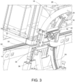
FIG. 3 is a side view of a portion of the arches in the apparatus shown inFIG. 1 ; -
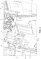
FIG. 4 is a side view of a portion of the arches in the apparatus shown inFIG. 1 in which the arches are engaged with each other; and, -
FIG. 5 is a side view of an indexing feature according to one or more aspects of the present invention. - For performing operations on a part, an apparatus according to the present disclosure utilizes arches extending between fixed beams. Some of the arms are moveable, longitudinally, allowing end effectors to be positioned at a desired location. Additionally, arches are provided in fixed positions. When it is desired to perform operations using the fixed arches, a movable arch is positioned at the fixed arch, and brought into engagement therewith. This allows the end effector to move to the fixed arch. Compared with other movement systems, the present movement system allows for fixed rails to be used that are not attached to the part. Additionally, it avoids the supports that hold up the part.
- With these general principles in mind, one or more embodiments of the present invention will be described with the understanding that the following description is not intended to be limiting.
- In
FIGS. 1 and2 , anapparatus 10 for performing operations on a part, such as an aircraft fuselage, includes atrack 12 extending in direction parallel with a longitudinal axis A1 of the part. Thetrack 12 preferably includes tworails 14 on opposite sides of the longitudinal axis A1. Therails 14, and thus thetrack 12, are fixed to a permanent support supporting structure. By "permanent" it is meant that therails 14 are not affixed, attached, otherwise supported by the part. - One or more movable arched beams, or arches, 16 are mounted to the
track 12, and extend between therails 14 by ameans 17 for moving the arch 16. For example, themeans 17 for moving the arch may be a motor having a gear which engages with atrack 12. As the motor turns the gear, the arch 16 may to move along the longitudinal axis A1. The direction of movement will depend on the direction of rotation of the gear. The motor means 17 may be mounted toplatform 19 configured to be moved with the arch 16 and which may be used to support controllers, power sources, and other components associated with theapparatus 10. - Specifically, the
movable arches 16 are configured to move along thetrack 12 and be positioned in a desired longitudinal location at which anend effector 18 is able to perform the operation on the part. For example, theend effector 18 may be configured to perform an operation, like drilling, or riveting. In addition to drilling or riveting, theend effectors 18 could be sprayers, for painting or coating, or distance sensors for measuring. - In the depicted embodiment, the
arches 16 are provided in pairs withsupports 20 extending therebetween. Theend effector 18 may be mounted to aplatform 22 or trolley that extends between thearches 16 in a particular pair. This may allow theend effector 18 to have additional longitudinal movement. Additionally, thearches 16 include gearedtracks 24 that allow theend effector 18 to move circumferentially around the longitudinal axis A1 (i.e., along the arch 16). - Accordingly, the
end effector 18, thanks to the longitudinal movement of the arch 16 may obtain the desired longitudinal position for performing the operation. Theend effector 18 may also obtain the desired circumferential position based on moving along the arch 16. Theend effector 18 may also have a radial movement, for example as part of theend effector 18 itself may extend (drill extending) or theend effector 18 may be mounted to an arm that may allow movement in the radial direction. - The
movable arches 16 are upper arches, allowing them to move freely along the longitudinal axis A1 without regard to supports and other equipment or devices located below the part. However, there is occasionally a need for theend effector 18 to perform the operation on the underside of the part. Accordingly, at specific locations, fixedarches 26, 28 may be provided. As will be described below, there may be some movement associated with these "fixed"arches 26, 28, but the longitudinal positioning of thesearches 26, 28 does not change. Hence, they are deemed to be "fixed"arches 26, 28. In the manufacturing of items repeatedly, it is known where there is a need for the end effector to be used on the underside of the part. Thus, the location of the fixed arches can be determined. - Accordingly, when the
movable arch 16 is positioned at the position of a fixedarch arches 26, 28, theend effector 18 moves from themoveable arch 16 to the fixedarch 26, 28. In some instances, the fixed arch 26 and themovable arch 16 may form a complete circle. Alternatively, the fixedarch 28 may only form part of a circle with themovable arch 16. This is particularly useful when theend effector 18 only needs to go a small distance circumferentially lower than themovable arch 16 allows. - Turning to
FIGS. 3 to 5 , in order to ensure proper alignment of themovable arch 16 with the fixedarch 26, 28 when theend effector 18 is to be moved, themovable arch 16 may include anextension 30 having an engagement surface, for example a T-shape 32. Theextension 30 may be movable with for example apiston 34. The fixedarch 26, 28 may include alatch 36 having an engagement surface, such as anorifice 38, configured complementarily to the engagement surface of theextension 30. - In use, the
piston 34 may being extending, resulting in theextension 30 moving towards the fixedarch 26, 28. Once theextension 30 has been lowered, themovable arch 18 may be moved longitudinally, so that the T-shape 32 of theextension 30 slides into theorifice 38 of thelatch 36. Once engaged as such, thepiston 34 can be retracted. The retraction of thepiston 34 will cause the fixedarch 26, 28 to be pulled upward towards themovable arch 16. - In order to further align the
movable arch 16 and the fixedarch 26, 28, as shown inFIG. 5 , one of thearches indexing feature 40 which will guide the fixedarch 26, 28, to the appropriate position. Theindexing feature 40 may be aprotrusion 42 with one or moreslanted surfaces 44 that is configured to be received in a correspondingly shaped aperture (not shown). Thus, as the twoarches surface 44 will be forced by the correspondingly shaped aperture to the correct, or proper, position. - Once in the correct position, see
FIG. 4 , the geared tracks 24 on themovable arch 16 and the geared tracks 24 on the fixedarch 26, 28 will be aligned, allowing the end effector 18 (or the trolley 22) to travel between the alignedarches arches - Thus, in a process for performing an operation on a part according to the present invention, a
first arch 16 is moved along atrack 12 to a desired longitudinal position. Thetrack 12 extends in a direction generally parallel (+/- 30 degrees) with a longitudinal axis A1 of the part. The desired position coincides with asecond arch 26, 28 fixed longitudinally relative to the desired longitudinal position. Anend effector 18 may be moved circumferentially around the longitudinal axis of the part from thefirst arch 16 to thesecond arch 26, 28 when desired and when the arches are aligned. - As will be appreciated, the present apparatus provides for precise, repeatable positioning for end effectors configured to perform operations on a part. The movable arches avoid supports and other devices and equipment located below the part. This allows for increased productivity. When use of the end effectors on the lower part is desired, fixed arches may be used which can receive the end effectors from the movable arches.
- The systems and devices described herein may include a controller or a computing device comprising a processing and a memory which has stored therein computer-executable instructions for implementing the processes described herein. The processing unit may comprise any suitable devices configured to cause a series of steps to be performed so as to implement the method such that instructions, when executed by the computing device or other programmable apparatus, may cause the functions/acts/steps specified in the methods described herein to be executed. The processing unit may comprise, for example, any type of general-purpose microprocessor or microcontroller, a digital signal processing (DSP) processor, a central processing unit (CPU), an integrated circuit, a field programmable gate array (FPGA), a reconfigurable processor, other suitably programmed or programmable logic circuits, or any combination thereof.
- The memory may be any suitable known or other machine-readable storage medium. The memory may comprise non-transitory computer readable storage medium such as, for example, but not limited to, an electronic, magnetic, optical, electromagnetic, infrared, or semiconductor system, apparatus, or device, or any suitable combination of the foregoing. The memory may include a suitable combination of any type of computer memory that is located either internally or externally to the device such as, for example, random-access memory (RAM), read-only memory (ROM), compact disc read-only memory (CDROM), electro-optical memory, magneto-optical memory, erasable programmable read-only memory (EPROM), and electrically-erasable programmable read-only memory (EEPROM), Ferroelectric RAM (FRAM) or the like. The memory may comprise any storage means (e.g., devices) suitable for retrievably storing the computer-executable instructions executable by processing unit.
- The methods and systems described herein may be implemented in a high-level procedural or object-oriented programming or scripting language, or a combination thereof, to communicate with or assist in the operation of the controller or computing device. Alternatively, the methods and systems described herein may be implemented in assembly or machine language. The language may be a compiled or interpreted language. Program code for implementing the methods and systems described herein may be stored on the storage media or the device, for example a ROM, a magnetic disk, an optical disc, a flash drive, or any other suitable storage media or device. The program code may be readable by a general or special-purpose programmable computer for configuring and operating the computer when the storage media or device is read by the computer to perform the procedures described herein.
- Computer-executable instructions may be in many forms, including modules, executed by one or more computers or other devices. Generally, modules include routines, programs, objects, components, data structures, etc., that perform particular tasks or implement particular abstract data types. Typically, the functionality of the modules may be combined or distributed as desired in various embodiments.
- While at least one exemplary embodiment of the present invention(s) is disclosed herein, it should be understood that modifications, substitutions and alternatives may be apparent to one of ordinary skill in the art and can be made without departing from the scope of this disclosure. This disclosure is intended to cover any adaptations or variations of the exemplary embodiment(s). In addition, in this disclosure, the terms "comprise" or "comprising" do not exclude other elements or steps, the terms "a" or "one" do not exclude a plural number, and the term "or" means either or both. Furthermore, characteristics or steps which have been described may also be used in combination with other characteristics or steps and in any order unless the disclosure or context suggests otherwise.
Claims (15)
- Apparatus (10) for performing an operation on a part, the apparatus (10) comprising:a track (12) extending in direction parallel with a longitudinal axis (A1) of the part;a first arch (16) mounted to the track (12), the first arch (16) configured to move along the track (12) to a longitudinal position;at least one end effector (18) associated with the first arch (16), the at least one end effector (18) configured to move circumferentially around the longitudinal axis (A1) of the part;a means (17) for moving the first arch (16), the means (17) for moving mounted to as to move with the first arch (16).
- Apparatus (10) according to claim 1, wherein the first arch (16) is formed from two parallel arches, wherein the end effector (18) is preferably mounted on a platform (19) that extends between the two parallel arches of the first arch (16).
- Apparatus (10) according to claim 1 or 2, wherein the track (12) comprises two rails (14) located on opposite sides of the part, wherein the first arch (16) preferably extends between the two rails (14) of the track (12).
- Apparatus (10) according to one of the claims 1 to 3 further comprising:
a second arch (26, 28) mounted to the track (12) in a fixed longitudinal position, wherein the end effector (18) is configured to move from the first arch (16) to the second arch (26, 28) when the first arch (16) is positioned at the fixed longitudinal position. - Apparatus (10) according to claim 4, wherein the second arch (26, 28) and the first arch (16) together form less than a complete circle around the part.
- Apparatus (10) according to claim 4 or 5, wherein the first arch (16) comprises an extension (30) having an engagement surface, and wherein the second arch (26, 28) comprises a latch (36) with an engagement surface configured complementarily to the engagement surface of the extension (30), wherein the engagement surface of the extension (30) preferably comprises a T-shape.
- Apparatus (10) according to claim 6, wherein the extension (30) is configured to be moved so as to allow the engagement surface of the extension (30) to engage with the engagement surface of the latch (36).
- Apparatus (10) according to claim 7, wherein one of the first arch (16) and the second arch (26, 28) comprises an indexing feature (40) configured to position the first and second arches (16, 26) together, wherein the indexing feature (40) preferably comprises a protrusion (42), which preferably comprises a slanted surface (44).
- Apparatus (10) according to one of the claims 4 to 8, further comprising a third arch mounted to the track (12) in a fixed longitudinal position, wherein the at least one end effector (18) is configured to move from the first arch (16) to the third arch when the first arch (16) is positioned at the fixed longitudinal position of the third arch.
- Apparatus (10) according to claim 9, wherein the second arch (26, 28) and the first arch (16) together form a complete circle around the part, and, wherein the third arch and the first arch (16) together form less than a complete circle around the part.
- Apparatus (10) according to one of the claims 4 to 10, wherein the first arch (16) is an upper arch and wherein the second arch (26, 28) is a lower arch.
- Apparatus (10) according to claim 11, further comprising a second upper arch.
- Process for performing an operation on a part, the process comprising:moving a first arch (16) along a track (12) to a desired longitudinal position, the track (12) extending in a direction parallel with a longitudinal axis (A1) of the part, wherein the desired longitudinal position coincides with a second arch (26, 28) fixed longitudinally relative to the desired longitudinal position; and,moving at least one end effector (18) circumferentially around the longitudinal axis (A1) of the part from the first arch (16) to the second arch (26, 28).
- Process according to claim 13 further comprising:
engaging an extension (30) on the first arch (16) with a latch (36) on the second arch (26, 28). - Process according to claim 13 or 14 wherein one of the first arch (16) or the second arch (26, 28) comprises a protrusion (42) configured to align the first arch (16) with the second arch (26, 28).
Applications Claiming Priority (1)
| Application Number | Priority Date | Filing Date | Title |
|---|---|---|---|
| US18/194,027 US12521868B2 (en) | 2023-03-31 | 2023-03-31 | Apparatuses and processes for working on a part |
Publications (1)
| Publication Number | Publication Date |
|---|---|
| EP4438224A1 true EP4438224A1 (en) | 2024-10-02 |
Family
ID=90366403
Family Applications (1)
| Application Number | Title | Priority Date | Filing Date |
|---|---|---|---|
| EP24163967.3A Pending EP4438224A1 (en) | 2023-03-31 | 2024-03-15 | Apparatus and process for working on a part |
Country Status (3)
| Country | Link |
|---|---|
| US (1) | US12521868B2 (en) |
| EP (1) | EP4438224A1 (en) |
| CN (1) | CN118720729A (en) |
Citations (4)
| Publication number | Priority date | Publication date | Assignee | Title |
|---|---|---|---|---|
| CH172622A (en) * | 1932-09-02 | 1934-10-15 | Lindner Herbert | Machine tool. |
| US20110132548A1 (en) * | 2009-11-17 | 2011-06-09 | Airbus Operations (S.A.S.) | Cylindrical composite part tape laying machine |
| CN107499530A (en) * | 2017-08-21 | 2017-12-22 | 大连四达高技术发展有限公司 | Digital processing and assembly system for aircraft panels |
| US20190168350A1 (en) * | 2016-04-29 | 2019-06-06 | Schirmer Maschinen Gmbh | Device for machining rod-shaped workpieces such as window profiles or door profiles |
Family Cites Families (12)
| Publication number | Priority date | Publication date | Assignee | Title |
|---|---|---|---|---|
| FR2630675B1 (en) | 1988-05-02 | 1994-09-09 | Aerospatiale | SYSTEM FOR PERFORMING OPERATIONS ON LARGE OBJECTS, IN PARTICULAR FOR PAINTING AN AIRCRAFT |
| US6098260A (en) * | 1996-12-13 | 2000-08-08 | Mcdonnell Douglas Corporation | Rivet fastening system for radial fuselage joints |
| US20060068109A1 (en) | 2004-09-15 | 2006-03-30 | Airbus Deutschland Gmbh | Painting device, painting arrangement, method for painting a curved surface of an object, and use of an inkjet device for painting an aircraft |
| US8296923B2 (en) * | 2007-11-29 | 2012-10-30 | Spirit Aerosystems, Inc. | Modular numerically controlled system |
| US9610693B2 (en) * | 2012-01-17 | 2017-04-04 | The Boeing Company | Robot for clamping onto upright frame members |
| KR20140039418A (en) * | 2012-09-21 | 2014-04-02 | 삼성전자주식회사 | Medical robot system |
| US10369679B2 (en) * | 2016-11-09 | 2019-08-06 | The Boeing Company | Apparatus, system and method for performing automated finishing operations on a workpiece |
| FR3060429B1 (en) | 2016-12-20 | 2019-07-26 | Airbus Operations | MACHINE TOOL HAVING MOUNTING CONFIGURATION WITH DOOR-A-FALSE TOOL |
| FR3061054B1 (en) | 2016-12-22 | 2019-06-14 | Airbus Operations | GUIDE DEVICE SUITABLE FOR POSITIONING ON A DOUBLE BEND RADIUS SURFACE |
| US10501208B2 (en) * | 2017-06-30 | 2019-12-10 | The Boeing Company | Gantry system and method for processing an aircraft |
| US20220153432A1 (en) * | 2020-11-18 | 2022-05-19 | The Boeing Company | Coordinated End Effector Attachment of Fasteners to Aircraft Structure |
| US12187456B2 (en) * | 2023-03-31 | 2025-01-07 | Airbus Operations Gmbh | System and method for a manufacturing environment with robotic system mounts having one or more end effectors positioned sympathetic to the underlying manufactured item |
-
2023
- 2023-03-31 US US18/194,027 patent/US12521868B2/en active Active
-
2024
- 2024-03-15 EP EP24163967.3A patent/EP4438224A1/en active Pending
- 2024-03-28 CN CN202410367395.2A patent/CN118720729A/en active Pending
Patent Citations (4)
| Publication number | Priority date | Publication date | Assignee | Title |
|---|---|---|---|---|
| CH172622A (en) * | 1932-09-02 | 1934-10-15 | Lindner Herbert | Machine tool. |
| US20110132548A1 (en) * | 2009-11-17 | 2011-06-09 | Airbus Operations (S.A.S.) | Cylindrical composite part tape laying machine |
| US20190168350A1 (en) * | 2016-04-29 | 2019-06-06 | Schirmer Maschinen Gmbh | Device for machining rod-shaped workpieces such as window profiles or door profiles |
| CN107499530A (en) * | 2017-08-21 | 2017-12-22 | 大连四达高技术发展有限公司 | Digital processing and assembly system for aircraft panels |
Also Published As
| Publication number | Publication date |
|---|---|
| US20240326235A1 (en) | 2024-10-03 |
| CN118720729A (en) | 2024-10-01 |
| US12521868B2 (en) | 2026-01-13 |
Similar Documents
| Publication | Publication Date | Title |
|---|---|---|
| CN110709214B (en) | Control method of surface treatment system | |
| ES2733453T3 (en) | Procedures for using an automated guided car | |
| US5477596A (en) | Stringer/clip placement and drilling | |
| EP1884453B1 (en) | Crawler robot equipped with a work unit, and control system for such crawler robots | |
| EP3076255A1 (en) | Automated dynamic manufacturing systems and related methods | |
| EP1166961A1 (en) | Grinding machine for simultaneously grinding the four edges of a glass sheet | |
| US11740605B2 (en) | Movable gantry system configured to interface with jigs of different sizes | |
| EP0028735A2 (en) | A machining center equipped with a robot device | |
| EP2631041A2 (en) | Mobile robot | |
| DE102012003663A1 (en) | Mobile robot, processing station and method for operating a mobile robot | |
| US20180250778A1 (en) | Machine for bending a thread-like material such as a pipe equipped with an aboard cutting device | |
| US20190143464A1 (en) | Automated assembly method and automated assembly apparatus | |
| DE102015220066A1 (en) | Haptic referencing of a manipulator | |
| WO2019096479A1 (en) | Method and means for operating a robot assembly | |
| US12521868B2 (en) | Apparatuses and processes for working on a part | |
| RU99104053A (en) | UNIVERSAL AUTOMATED COMPLEX FOR BASING OF LARGE-SIZED HYDRAULIC FORMING PARTS, THEIR MECHANICAL PROCESSING AND ASSEMBLY (KBMOS) AND METHOD FOR ITS ADJUSTMENT | |
| CN113579770A (en) | Multifunctional large-scale external preset loading and unloading platform | |
| CN108311901B (en) | Automatic positioning clamp system and positioning method thereof | |
| US6876897B2 (en) | Positioning device and method for operation | |
| CN109623595B (en) | Automatic grinding equipment of thin-wall multi-pass workpiece robot | |
| GB2483891A (en) | Method and apparatus for modifying a panel | |
| JPH0288109A (en) | Drilling device of plate material | |
| DE102019212186A1 (en) | Machining system and method for performing track work | |
| JP2000061870A (en) | Return-to-origin method for robot | |
| US3093017A (en) | Spar riveting machine |
Legal Events
| Date | Code | Title | Description |
|---|---|---|---|
| PUAI | Public reference made under article 153(3) epc to a published international application that has entered the european phase |
Free format text: ORIGINAL CODE: 0009012 |
|
| STAA | Information on the status of an ep patent application or granted ep patent |
Free format text: STATUS: THE APPLICATION HAS BEEN PUBLISHED |
|
| AK | Designated contracting states |
Kind code of ref document: A1 Designated state(s): AL AT BE BG CH CY CZ DE DK EE ES FI FR GB GR HR HU IE IS IT LI LT LU LV MC ME MK MT NL NO PL PT RO RS SE SI SK SM TR |
|
| STAA | Information on the status of an ep patent application or granted ep patent |
Free format text: STATUS: REQUEST FOR EXAMINATION WAS MADE |
|
| 17P | Request for examination filed |
Effective date: 20250319 |