EP4437829B1 - Tragbares landwirtschaftliches werkzeug - Google Patents
Tragbares landwirtschaftliches werkzeug Download PDFInfo
- Publication number
- EP4437829B1 EP4437829B1 EP23219016.5A EP23219016A EP4437829B1 EP 4437829 B1 EP4437829 B1 EP 4437829B1 EP 23219016 A EP23219016 A EP 23219016A EP 4437829 B1 EP4437829 B1 EP 4437829B1
- Authority
- EP
- European Patent Office
- Prior art keywords
- connecting rod
- tool
- crank
- rotation
- sliding path
- Prior art date
- Legal status (The legal status is an assumption and is not a legal conclusion. Google has not performed a legal analysis and makes no representation as to the accuracy of the status listed.)
- Active
Links
Images


Classifications
-
- A—HUMAN NECESSITIES
- A01—AGRICULTURE; FORESTRY; ANIMAL HUSBANDRY; HUNTING; TRAPPING; FISHING
- A01D—HARVESTING; MOWING
- A01D46/00—Picking of fruits, vegetables, hops, or the like; Devices for shaking trees or shrubs
- A01D46/26—Devices for shaking trees or shrubs; Fruit catching devices to be used therewith
- A01D46/264—Devices for beating or vibrating the foliage; Fruit catching devices to be used therewith
-
- A—HUMAN NECESSITIES
- A01—AGRICULTURE; FORESTRY; ANIMAL HUSBANDRY; HUNTING; TRAPPING; FISHING
- A01D—HARVESTING; MOWING
- A01D46/00—Picking of fruits, vegetables, hops, or the like; Devices for shaking trees or shrubs
- A01D46/26—Devices for shaking trees or shrubs; Fruit catching devices to be used therewith
- A01D2046/266—Portable devices to shake branches
Definitions
- the present invention falls within the agricultural sector and concerns a portable agricultural tool, such as a harvester.
- Agricultural tools comprising a machine body equipped with a motor and a utensil configured to make the fruit fall, which is connected to the machine body motor by means of a mechanical transmission.
- agricultural tools of the harvester type are equipped with a utensil comprising a pair of combs that cause the fruit to fall by means of fast vibration (over 1000 beats per minute).
- an olive shaking machine used in olive harvesting is known from WO2020/101591 .
- This machine is a so-called “olive harvester” and provides high torque at low speeds by transmitting the rotational movement received from the engine's drive gears to a plurality of timing gears, and to the curved connecting rods by means of the timing gears.
- each comb is moved according to a tilting movement.
- the pair of combs is typically moved at the same frequency.
- the combs define a plurality of mutual movement configurations depending on the timing of the tilting movement of the combs themselves.
- a specific comb operating configuration depending on parameters such as the size and type of fruit tree as well as the size and state of ripeness of the fruit to be harvested.
- two mutual comb movement configurations are known to be very efficient: a first configuration in which the combs are moved in phase and a second configuration in which the combs are moved in counterphase.
- a strongly felt need is therefore to be able to convert the mutual movement configuration of the combs (in particular by switching from the phase configuration to the counterphase configuration and vice versa) so that the harvester can be adapted to operate optimally according to these parameters.
- One attempt to solve this need has been to sell harvesters with the head tool (i.e. the pair of combs) interchangeable.
- the machine body of the harvester is known to be sold in combination with two or more head tools, each configured to operate at a predetermined configuration of mutual comb movement.
- the technical task of the present invention is therefore to make available a portable agricultural tool, such as a harvester, that is free of the drawbacks complained of in the known technique.
- the purpose of the present invention is therefore to make available a portable agricultural tool, such as a harvester, that is versatile and at the same time inexpensive and easy to use.
- a further purpose of the present invention is to make available a portable agricultural tool, such as a harvester, with a simplified structure that is more resistant to damage.
- the numerical reference “1" indicates a portable agricultural tool.
- the tool 1 is of the "harvester” type.
- the present invention is extended to any portable agricultural tool presenting a utensil comprising two elements that are mutually movable according to a periodic movement, in accordance with the generality of the invention.
- the tool 1 comprises a machine body, not illustrated, comprising a motor 3 configured to selectively operate in a first drive direction and a second drive direction opposite the first drive direction.
- the operator can selectively drive the motor 3 in the first drive direction or in the second drive direction.
- the tool 1 comprises an operator-driven control connected to the motor 3 and configured to switch the tool 1 on and off and to switch the drive direction of the motor 3.
- the machine body has a rod that extends longitudinally along a longitudinal axis "Z".
- the tool 1 comprises a utensil 4 operatively arranged on one end of the rod.
- the tool 4 is connected to the motor 3 by means of a mechanical transmission 2.
- the tool 4 comprises a first comb 10 and a second comb 20 connected to the motor 3 by means of the aforementioned mechanical transmission 2.
- the combs 10, 20 have a mutually specular conformation with respect to the longitudinal axis "Z" of the tool 1.
- the mechanical transmission 2 comprises a first connecting rod-crank mechanism 100 configured to move the first comb 10 and a second connecting rod-crank mechanism 200 configured to move the second comb 20.
- each connecting rod-crank mechanism 100, 200 comprises a main body 101, 201 fitted to rotate about a respective axis of rotation "X", "Y".
- the main bodies 101, 201 are mutually concordant in rotation.
- Each connecting rod-crank mechanism 100, 200 further comprises a connecting rod 102, 202 having a first end 102a, 202a hinged to the respective comb 10, 20 and a second end 102b, 202b hinged to the main body 101, 201.
- the second end 102b, 202b of the connecting rod 102, 202 is hinged to the main body 101, 201 in a respective crank pin 103, 203.
- each main body 101, 201 is at least partially circular in shape. Even more preferably, each main body 101, 201 has a gear wheel shape.
- the main bodies 101, 201 of the two connecting rod-crank mechanisms 100, 200 have the same diameter and the two connecting rods 102, 202 of the two connecting rod-crank mechanisms 100, 200 have the same length.
- the main body 101, 201 of the first and/or second connecting rod-crank mechanism 100, 200 defines a sliding path 104, 204 for the respective crank pin 103, 203.
- the sliding path 104, 204 is delimited by a first end stop 105, 205 and a second end stop 106, 206.
- the sliding path 104, 204 extends around the respective axis of rotation "X", "Y”.
- the sliding path 104, 204 extends in an arc-of-a-circle about the respective axis of rotation "X", "Y”.
- the crank pin 103, 203 abuts against the first end stop 105, 205 so that the two combs 10, 20 mutually take on a first tilting configuration whereas when the motor 3 operates according to the second drive direction, the crank pin 103, 203 abuts against the second end stop 106, 206 so that the two combs 10, 20 mutually take on a second tilting configuration, which is offset from the first tilting configuration.
- this system allows the mutual tilting configuration to be switched between the two combs 10, 20.
- the tool 1 can selectively operate in the first drive direction of the motor 3 in which the combs 10, 20 assume a mutual tilting configuration and in the second drive direction in which the combs 10, 20 assume a further mutual tilting configuration, different from the previous one.
- the two combs 10, 20 are moved by the respective connecting rod-crank mechanisms 100, 200 so that they are mutually in phase.
- the two combs 10, 20 move concordantly.
- the two combs 10, 20 are driven by the respective connecting rod-crank mechanisms 100, 200 so that they are mutually in counterphase.
- the two combs 10, 20 move in opposite directions.
- the two combs 10, 20 are instead moved by the respective connecting rod-crank mechanisms 100, 200 so that they are mutually offset by a predetermined phase delay.
- the two combs 10, 20 are moved by the respective connecting rod-crank mechanisms 100, 200 so that they are in counterphase.
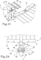
- Figures 1A-1C show a first possible embodiment of the mechanical transmission 2.
- the main bodies 101, 201 of the two connecting rod-crank mechanisms 100, 200 are coplanar and placed side-by-side along a longitudinal axis "Z" of the tool 1.
- the axes of rotation "X", "Y" of the two main bodies 101, 201 are parallel.
- only one of the connecting rod-crank mechanisms 100, 200 defines the sliding path 104, 204 for the respective crank pin 103, 203.
- the first connecting rod-crank mechanism 100 defines the respective sliding path 104.
- the sliding path 104 is defined by a groove or slot 110 obtained on the respective main body 101, to which the second end 102b, of the respective connecting rod 102 is slidably coupled.
- the main bodies 101, 201 of the two connecting rod-crank mechanisms 100, 200 begin to rotate in the corresponding drive direction.
- the connecting rod 102 slidably constrained in the respective sliding path 104, slides along the sliding path 104 from the first end-stop 105 to the second end-stop 106 in a manner not integral with the respective main body 101 so as to remain substantially stationary with respect to the axis of rotation "X" of the main body 101 and so as not to move the respective comb 10, which accumulates a phase delay with respect to the comb 20 connected to the second connecting rod-crank mechanism 200.
- Figures 2A-2C show a second possible embodiment of the mechanical transmission 2.
- the main bodies 101, 201 of the two connecting rod-crank mechanisms 100, 200 are coplanar and placed side-by-side along a longitudinal axis "Z" of the tool 1.
- the axes of rotation "X", "Y" of the two main bodies 101, 201 are parallel.
- the mechanical transmission 2 comprises a pinion 300 operatively connected to and active on both main bodies 101, 201 of the two connecting rod-crank mechanisms 100, 200.
- the pinion 300 is operatively arranged substantially along the longitudinal axis "Z" of the tool 1 and is operatively arranged in a position interposed between the two main bodies 101, 201.
- both connecting rod-crank mechanisms 100, 200 define their own sliding path 104, 204 for the respective crank pins 103, 203.
- the first connecting rod-crank mechanism 100 defines a first sliding path 104 for the respective crank pin 103
- the second connecting rod-crank mechanism 200 defines a second sliding path 204 for the respective crank pin 203:
- the first and second sliding paths 104, 204 extend angularly about the respective axes of rotation "X", "Y" having an angular extension difference comprised between 10° and 210°.
- the two sliding paths 104, 204 have a difference in angular extension of 180° so that in the second tilting configuration, the two combs 10, 20 are mutually moved in counterphase.
- Figure 1A shows the second tilting configuration. Specifically, in the second drive direction of the motor 3, the main bodies 101, 201 rotate clockwise, while in the first drive direction of the motor 3, the main bodies 101, 201 rotate anticlockwise.
- the sliding path 104 of the first connecting rod-crank mechanism 100 extends at an angle of 270° about the respective axis of rotation "X", while the sliding path 204 of the second connecting rod-crank mechanism 200 extends at an angle of 90° about the respective axis of rotation "Y".
- each sliding path 104, 204 is defined by a groove or slot 110, 210 obtained on the respective main body 101, 201, to which the second end 102b, 202b of the respective connecting rod 102, 202 is slidably coupled.
- both connecting rods 102, 202 which are slidably constrained in the respective sliding path 104, 204, slide along the sliding path 104, 204 from the first end-stop 105, 205 to the second end-stop 106, 206 in a manner not integral with the respective main body 101, 201 so as to remain substantially stationary with respect to the axis of rotation "X" of the main body 101, 201 and so as not to move the respective comb 10, 20.
- the connecting rod 202 of the second connecting rod-crank mechanism 200 comes into contact with the respective second end-stop 206 before the connecting rod 102 of the first connecting rod-crank mechanism 100.
- the connecting rod By reversing the drive direction of the motor 3 again, in particular from the second drive direction to the first drive direction, the connecting rod returns to abut against the first end stop 105 of the respective sliding path 104, so that the two combs are again mutually moved in phase.
- Figure 2A shows the second tilting configuration. Specifically, in the second drive direction of the motor 3, the main bodies 101, 201 rotate clockwise, while in the first drive direction of the motor 3, the main bodies 101, 201 rotate anticlockwise.
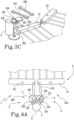
- Figures 3A-3C show a third possible embodiment of the mechanical transmission 2.
- the main bodies 101, 201 of the two connecting rod-crank mechanisms 100, 200 are coplanar and placed side-by-side along a longitudinal axis "Z" of the tool 1.
- the axes of rotation "X", "Y" of the two main bodies 101, 201 are parallel.
- the mechanical transmission 2 comprises a pinion 300 operatively connected to only one of the main bodies 101, 201 of the two connecting rod-crank mechanisms 100, 200 while the other main body 201, 101 is connected in a cascaded system.
- the pinion 300 directly moves the main body 101 of the first connecting rod-crank mechanism 100 while the main body 201 of the second connecting rod-crank mechanism 200 is operatively connected to the main body 101 of the first connecting rod-crank mechanism 100 so as to be moved by it.
- only one of the connecting rod-crank mechanisms 100, 200 defines the sliding path 104, 204 for the respective crank pin 103, 203, as in the embodiment of Figures 1A-1C .
- the first connecting rod-crank mechanism 100 defines the respective sliding path 104.
- the sliding path 104 extends angularly for an angle comprised between 10° and 210° about the respective axis of rotation "X".
- the sliding path 104 extends angularly for 180° about the respective axis of rotation "X" so that in the second tilting configuration the two combs 10, 20 are mutually moved in counterphase.
- this embodiment operates essentially like the embodiment of Figures 1A-1C .
- Figure 3A shows the second tilting configuration. Specifically, in the second drive direction of the motor 3, the main bodies 101, 201 rotate clockwise, while in the first drive direction of the motor 3, the main bodies 101, 201 rotate anticlockwise.
- Figures 4A-4C show a fourth possible embodiment of the mechanical transmission 2.
- the main bodies 101, 201 of the two connecting rod-crank mechanisms 100, 200 are coplanar and placed side-by-side along a longitudinal axis "Z" of the tool 1.
- the axes of rotation "X", "Y" of the two main bodies 101, 201 are parallel.
- the mechanical transmission 2 comprises a pinion 300 operatively connected to and active on both main bodies 101, 201 of the two connecting rod-crank mechanisms 100, 200.
- the pinion 300 is operatively arranged substantially along the longitudinal axis "Z" of the tool 1 and is operatively arranged in a position interposed between the two main bodies 101, 201.
- only one of the connecting rod-crank mechanisms 100, 200 defines the sliding path 104, 204 for the respective crank pin 103, 203.
- the first connecting rod-crank mechanism 100 defines the respective sliding path 104.
- the sliding path 104 extends angularly for an angle comprised between 10° and 210° about the respective axis of rotation "X".
- the sliding path 104 extends angularly for 180° about the respective axis of rotation "X" so that in the second tilting configuration the two combs 10, 20 are mutually moved in counterphase.
- the first connecting rod-crank mechanism 100 comprises an intermediate body 120 hinged to the respective main body 101 so as to be rotatable about the respective axis of rotation "X"; the second end 102b of the respective connecting rod 102 is integrally hinged to the intermediate body 120 in a radially peripheral portion thereof.
- the main body 101 and the respective intermediate body 120 have mutual blocking elements 131, 132, such as protuberances and/or recesses, defining the first end-stop 104a and the second end-stop 104b so that the intermediate body 120 is rotatable relative to the respective main body 101 between two positions defining respectively the two tilting configurations 10, 20.
- mutual blocking elements 131, 132 such as protuberances and/or recesses
- the sliding path 104 is essentially defined by the mutual movement of the intermediate body 120 with respect to the main body 101 on which it is constrained and pivots between the aforementioned two positions, defined in turn by the blocking elements 131, 132.
- the intermediate body 120 has a recess or slot 132 while the main body 101 has a protuberance 131 operatively inserted into the recess or slot 132 of the intermediate body 120.
- the protuberance 131 of the main body 101 defines the aforementioned first end stop 105 and second end stop 106.
- this embodiment operates essentially similarly to the embodiment in Figures 1A-1C .
- Figure 4A shows the second tilting configuration. Specifically, in the second drive direction of the motor 3, the main bodies 101, 201 rotate clockwise, while in the first drive direction of the motor 3, the main bodies 101, 201 rotate anticlockwise.
- the main bodies 101, 201 of the two connecting rod-crank mechanisms 100, 200 are integral or permanently connected so as to be integral and are rotatable about the same axis of rotation "X", "Y"; the main bodies 101, 201 define a double discoidal body to which the connecting rods 102, 202 are rotatably connected on opposite sides of the double discoidal body itself.
- the sliding paths can be realised in accordance with the embodiments described above.
- only one of the connecting rod-crank mechanisms 100, 200 can be provided to describe the respective sliding path 104, 204 in accordance with the above.
- both connecting rod-crank mechanisms 100, 200 describe the respective sliding paths 104, 204 in accordance with the above.
- the present invention achieves the intended purposes by eliminating the drawbacks highlighted by the prior art: in this regard, it should first be noted that the tool 1 as described and/or claimed allows for selectively varying the mutual movement configuration of the combs by reversing the direction of the motor drive, thus making the tool 1 itself extremely versatile and, at the same time, easy to use. It should also be noted that by eliminating the need to have multiple utensils available, each configured for a specific operating configuration, the tool is also inexpensive and more resistant to damage. Finally, the tool in accordance with what is described and/or claimed has a mechanical transmission such that it is versatile and structurally simplified.
Landscapes
- Life Sciences & Earth Sciences (AREA)
- Environmental Sciences (AREA)
- Transmission Devices (AREA)
Claims (12)
- Tragbares landwirtschaftliches Werkzeug (1), wie z.B. eine Mähmaschine, umfassend:- einen Maschinenkörper umfassend einen Motor (3);- einen ersten Kamm (10) und einen zweiten Kamm (20), die mit dem Motor (3) über ein mechanisches Getriebe (2) verbunden sind, das einen ersten Verbindungsstange-Kurbel-Mechanismus (100), der dazu konfiguriert ist, den ersten Kamm (10) zu bewegen, und einen zweiten Verbindungsstange-Kurbel-Mechanismus (200), der dazu konfiguriert ist, den zweiten Kamm (20) zu bewegen, umfasst; jeder Verbindungsstange-Kurbel-Mechanismus (100, 200) umfassend einen Hauptkörper (101, 201), der um eine jeweilige Drehachse (X, Y) drehbar ist, und eine Verbindungsstange (102, 202) aufweisend ein erstes Ende (102a, 202a), das an dem jeweiligen Kamm (10, 20) angelenkt wird, und ein zweites Ende (102b, 202b), das an einem jeweiligen Hauptkörper (101, 201) in einem jeweiligen Kurbelzapfen (103, 203) angelenkt wird; wobei die Hauptkörper (101, 201) im Gebrauch bei der Drehung zueinander übereinstimmen;dadurch gekennzeichnet, dass der Motor (3) dazu konfiguriert ist, selektiv in einer ersten Antriebsrichtung und einer zweiten Antriebsrichtung, die entgegengesetzt zu der ersten Antriebsrichtung ist, zu arbeiten, und dassder Hauptkörper (101, 201) des ersten und/oder des zweiten Verbindungsstange-Kurbel-Mechanismus (100, 200) eine Gleitbahn (104, 204) für den jeweiligen Kurbelzapfen (103, 203) definiert, wobei die Gleitbahn (103, 203) durch einen ersten Endanschlag (104a, 204a) und einen zweiten Endanschlag (104b, 204b) begrenzt wird und sich um die jeweilige Drehachse (X, Y) erstreckt, so dass:wenn der Motor (3) nach der ersten Antriebsrichtung arbeitet, liegt der Kurbelzapfen (103, 203) auf den ersten Endanschlag (104a, 204a) auf, so dass die zwei Kämme (10, 20) gegenseitig eine erste Kippkonfiguration einnehmen; undwenn der Motor (3) in der zweiten Antriebsrichtung arbeitet, liegt der Kurbelzapfen (103, 203) auf den zweiten Endanschlag (104b, 204b) auf, so dass die zwei Kämme (10, 20) gegenseitig eine zweite Kippstellung einnehmen, die gegenüber der ersten Kippstellung versetzt ist.
- Werkzeug (1) nach Anspruch 1, wobei die zwei Kämme (10, 20) in der ersten Kippkonfiguration durch die jeweiligen Verbindungsstange-Kurbel-Mechanismen (100, 200) bewegt werden, sodass sie zueinander in Phase sind.
- Werkzeug (1) nach Anspruch 1 oder 2, wobei jeder Hauptkörper (101, 201) eine Zahnrad-Gestalt aufweist und wobei sich die Gleitbahn (104, 204) in einem Kreisbogen um die jeweilige Drehachse (X, Y) erstreckt; wobei die Hauptkörper (101, 201) der beiden Verbindungsstange-Kurbel-Mechanismen (100, 200) vorzugsweise den gleichen Durchmesser aufweisen und die zwei Verbindungsstange (102, 202) der zwei Verbindungsstange-Kurbel-Mechanismen (100, 200) die gleiche Länge aufweisen.
- Werkzeug (1) nach einem der vorhergehenden Ansprüche, wobei nur einer der Verbindungsstange-Kurbel-Mechanismen (100, 200) die Gleitbahn (104, 204) für den jeweiligen Kurbelzapfen (103, 203) definiert und wobei sich die Gleitbahn (104, 204) in einem Winkel zwischen 10° und 210° um die jeweilige Drehachse (X, Y) erstreckt, wobei sich die Gleitbahn(104, 204) vorzugsweise in einem Winkel von 180° um die jeweilige Drehachse (X, Y) erstreckt, so dass die zwei Kämme (10, 20) in der zweiten Kippkonfiguration gegenseitig zueinander bewegt werden.
- Werkzeug (1) nach einem der vorhergehenden Ansprüche 1 bis 3, wobei der erste Verbindungsstange-Kurbel-Mechanismus (100) eine erste Gleitbahn (104) für den jeweiligen Kurbelzapfen (103) definiert und wobei der zweite Verbindungsstange-Kurbel-Mechanismus (200) eine zweite Gleitbahn (204) für den jeweiligen Kurbelzapfen (203) definiert;
wobei die erste und die zweite Gleitbahnen (104, 204) sich winklig um ihre jeweiligen Drehachsen (X, Y) erstrecken und eine Differenz in der Winkelausdehnung zwischen 10° und 210° aufweisen, wobei vorzugsweise die beiden Gleitbahnen (104, 204) eine Differenz in der Winkelausdehnung von 180° aufweisen, so dass die zwei Kämme (10, 20) in der zweiten Kippkonfiguration gegenseitig zueinander bewegt werden. - Werkzeug (1) nach einem der vorhergehenden Ansprüche, wobei die Gleitbahn (104, 204) durch eine Nut oder einen Schlitz (110, 210) definiert wird, die bzw. der an dem jeweiligen Hauptkörper (101, 201) ausgebildet werden und mit der bzw. dem das zweite Ende (102b, 202b) der jeweiligen Verbindungsstange (102, 202) gleitend gekoppelt wird.
- Werkzeug (1) nach einem der vorhergehenden Ansprüche 1 bis 5, wobei der erste und/oder zweite Verbindungsstange-Kurbel-Mechanismus (100, 200) einen Zwischenkörper (120) umfasst, der an dem jeweiligen Hauptkörper (101) angelenkt wird, sodass er um die jeweilige Drehachse (X) drehbar ist; wobei das zweite Ende (102b) der jeweiligen Verbindungsstange (102) einstückig an dem Zwischenkörper (120) in einem radialen Umfangsabschnitt davon angelenkt wird;
wobei der Hauptkörper (101) und der jeweilige Zwischenkörper (120) gegenseitige Blockierelemente (131, 132), wie Vorsprünge und/oder Ausnehmungen, aufweisen, die den ersten Endanschlag (104a) und den zweiten Endanschlag (104b) definieren, so dass der Zwischenkörper (120) in Bezug auf den jeweiligen Hauptkörper (101) zwischen zwei Positionen drehbar ist, die jeweils die zwei Kippkonfigurationen (10, 20) definieren. - Werkzeug (1) nach einem der vorhergehenden Ansprüche, wobei die Hauptkörper (101, 201) der zwei Verbindungstange-Kurbel-Mechanismen (100, 200) koplanar sind und nebeneinander entlang einer Längsachse (Z) des Werkzeugs (1) angeordnet sind; wobei die Drehachsen (X, Y) der beiden Hauptkörper (101, 201) parallel sind.
- Werkzeug (1) nach einem der vorhergehenden Ansprüche 1 bis 7, wobei die Hauptkörper (101, 201) der zwei Verbindungsstange-Kurbel-Mechanismen (100, 200) einstückig ausgebildet sind oder dauerhaft verbunden sind, so dass sie einstückig ausgebildet sind, und um dieselbe Drehachse (X, Y) drehbar sind; wobei die Hauptkörper (101, 201) einen doppelscheibenförmigen Körper definieren, mit dem die Verbindungsstangen (102, 202) auf gegenüberliegenden Seiten des doppelscheibenförmigen Körpers drehbar verbunden sind.
- Werkzeug (1) nach einem der vorhergehenden Ansprüche, wobei das mechanische Getriebe (2) ein Ritzel (300) umfasst, das operativ mit beiden Hauptkörpern (101, 201) der zwei Verbindungsstange-Kurbel-Mechanismen (100, 200) verbunden ist und auf diese einwirkt.
- Werkzeug (1) nach einem der vorhergehenden Ansprüche 1 bis 9, wobei das mechanische Getriebe (20) ein Ritzel (300) umfasst, das operativ nur mit einem der Hauptkörper (101, 201) der zwei Verbindungsstange-Kurbel-Mechanismen (100, 200) verbunden ist, während der andere Hauptkörper (201, 101) in einem kaskadierten System verbunden ist.
- Werkzeug (1) nach Anspruch 1, wobei die zwei Kämme (10, 20) in der ersten Kippkonfiguration durch die jeweiligen Verbindungsstange-Kurbel-Mechanismen (100, 200) bewegt werden, sodass sie gegenseitig in Gegenphase angeordnet sind.
Applications Claiming Priority (1)
| Application Number | Priority Date | Filing Date | Title |
|---|---|---|---|
| IT202300005727 | 2023-03-27 |
Publications (3)
| Publication Number | Publication Date |
|---|---|
| EP4437829A1 EP4437829A1 (de) | 2024-10-02 |
| EP4437829B1 true EP4437829B1 (de) | 2025-05-14 |
| EP4437829C0 EP4437829C0 (de) | 2025-05-14 |
Family
ID=86942602
Family Applications (1)
| Application Number | Title | Priority Date | Filing Date |
|---|---|---|---|
| EP23219016.5A Active EP4437829B1 (de) | 2023-03-27 | 2023-12-21 | Tragbares landwirtschaftliches werkzeug |
Country Status (2)
| Country | Link |
|---|---|
| EP (1) | EP4437829B1 (de) |
| ES (1) | ES3030270T3 (de) |
Family Cites Families (4)
| Publication number | Priority date | Publication date | Assignee | Title |
|---|---|---|---|---|
| FR2909517B1 (fr) * | 2006-12-11 | 2011-06-24 | Infaco | Appareil a main pour la cueillette mecanique des fruits par gaulage. |
| DE102012017963A1 (de) * | 2012-09-12 | 2014-03-13 | Andreas Stihl Ag & Co. Kg | Handgeführtes Arbeitsgerät mit einer Ansteuerschaltung für einen oszillierende Werkzeuge antreibenden Elektromotor |
| WO2020101591A2 (en) | 2018-06-19 | 2020-05-22 | Demi̇rayak Tarim Maki̇nalari Ve Tarim Ürünleri̇ İthalat İhracat Sanayi̇ Ve Ti̇caret Li̇mi̇ted Şi̇rketi̇ | An olive harvesting machine with a gear box providing freedom of comb movement |
| FR3112266B1 (fr) * | 2020-07-09 | 2023-01-20 | Innovation Fabrication Commercialisation Infaco | Vibreur électroportatif pour la récolte de fruits |
-
2023
- 2023-12-21 EP EP23219016.5A patent/EP4437829B1/de active Active
- 2023-12-21 ES ES23219016T patent/ES3030270T3/es active Active
Also Published As
| Publication number | Publication date |
|---|---|
| ES3030270T3 (en) | 2025-06-27 |
| EP4437829C0 (de) | 2025-05-14 |
| EP4437829A1 (de) | 2024-10-02 |
Similar Documents
| Publication | Publication Date | Title |
|---|---|---|
| US11224161B2 (en) | Cutter assembly for an agricultural harvester | |
| CN107920471B (zh) | 振荡式园艺器具、传动元件和应用振荡式园艺器具的方法 | |
| CN106246851B (zh) | 往复运动作业机 | |
| AU2018363673B2 (en) | Cutting unit for an agricultural harvesting machine | |
| EP4437829B1 (de) | Tragbares landwirtschaftliches werkzeug | |
| US5271154A (en) | Reciprocating saw blade unit | |
| DK3131382T3 (en) | Cutting Leaf Drive | |
| CN118556511A (zh) | 安装于采摘机械手末端的夹剪组合机构 | |
| CN211721120U (zh) | 一种切割器机构及稻麦联合收割机 | |
| CN106068918B (zh) | 收割设备和用于收割设备的耙 | |
| JP4811981B2 (ja) | コンバインにおけるクラッチ操作装置 | |
| WO2026003658A1 (en) | Portable agricultural tool | |
| US3436033A (en) | Line spreading device in fishing reels | |
| KR20130044064A (ko) | 양날회전이 가능한 예초기 칼날 구동장치 및 칼날 구동 방법과 그 칼날 구조 | |
| JP4657094B2 (ja) | 刈込機 | |
| JPH0617434U (ja) | バリカン形刈払機 | |
| JPS6341Y2 (de) | ||
| JP2026020910A (ja) | 刈刃装置 | |
| CN111083988A (zh) | 一种切割器及稻麦联合收割机 | |
| US20260027741A1 (en) | Cutting blade apparatus | |
| JPH0531877Y2 (de) | ||
| JPS6216341Y2 (de) | ||
| CN108672950A (zh) | 一种磁条单头多路径激光切割装置 | |
| JPH09172841A (ja) | 刈払機 | |
| EA040056B1 (ru) | Режущий аппарат для сельскохозяйственной уборочной машины |
Legal Events
| Date | Code | Title | Description |
|---|---|---|---|
| PUAI | Public reference made under article 153(3) epc to a published international application that has entered the european phase |
Free format text: ORIGINAL CODE: 0009012 |
|
| STAA | Information on the status of an ep patent application or granted ep patent |
Free format text: STATUS: THE APPLICATION HAS BEEN PUBLISHED |
|
| AK | Designated contracting states |
Kind code of ref document: A1 Designated state(s): AL AT BE BG CH CY CZ DE DK EE ES FI FR GB GR HR HU IE IS IT LI LT LU LV MC ME MK MT NL NO PL PT RO RS SE SI SK SM TR |
|
| STAA | Information on the status of an ep patent application or granted ep patent |
Free format text: STATUS: REQUEST FOR EXAMINATION WAS MADE |
|
| 17P | Request for examination filed |
Effective date: 20241021 |
|
| RBV | Designated contracting states (corrected) |
Designated state(s): AL AT BE BG CH CY CZ DE DK EE ES FI FR GB GR HR HU IE IS IT LI LT LU LV MC ME MK MT NL NO PL PT RO RS SE SI SK SM TR |
|
| P01 | Opt-out of the competence of the unified patent court (upc) registered |
Free format text: CASE NUMBER: APP_63778/2024 Effective date: 20241202 |
|
| GRAP | Despatch of communication of intention to grant a patent |
Free format text: ORIGINAL CODE: EPIDOSNIGR1 |
|
| STAA | Information on the status of an ep patent application or granted ep patent |
Free format text: STATUS: GRANT OF PATENT IS INTENDED |
|
| RIC1 | Information provided on ipc code assigned before grant |
Ipc: A01D 46/26 20060101AFI20250206BHEP |
|
| INTG | Intention to grant announced |
Effective date: 20250224 |
|
| GRAS | Grant fee paid |
Free format text: ORIGINAL CODE: EPIDOSNIGR3 |
|
| GRAA | (expected) grant |
Free format text: ORIGINAL CODE: 0009210 |
|
| STAA | Information on the status of an ep patent application or granted ep patent |
Free format text: STATUS: THE PATENT HAS BEEN GRANTED |
|
| AK | Designated contracting states |
Kind code of ref document: B1 Designated state(s): AL AT BE BG CH CY CZ DE DK EE ES FI FR GB GR HR HU IE IS IT LI LT LU LV MC ME MK MT NL NO PL PT RO RS SE SI SK SM TR |
|
| REG | Reference to a national code |
Ref country code: GB Ref legal event code: FG4D |
|
| REG | Reference to a national code |
Ref country code: CH Ref legal event code: EP |
|
| REG | Reference to a national code |
Ref country code: IE Ref legal event code: FG4D |
|
| U01 | Request for unitary effect filed |
Effective date: 20250514 |
|
| U07 | Unitary effect registered |
Designated state(s): AT BE BG DE DK EE FI FR IT LT LU LV MT NL PT RO SE SI Effective date: 20250520 |
|
| P04 | Withdrawal of opt-out of the competence of the unified patent court (upc) registered |
Free format text: CASE NUMBER: APP_23411/2025 Effective date: 20250516 |
|
| REG | Reference to a national code |
Ref country code: ES Ref legal event code: FG2A Ref document number: 3030270 Country of ref document: ES Kind code of ref document: T3 Effective date: 20250627 |
|
| PG25 | Lapsed in a contracting state [announced via postgrant information from national office to epo] |
Ref country code: NO Free format text: LAPSE BECAUSE OF FAILURE TO SUBMIT A TRANSLATION OF THE DESCRIPTION OR TO PAY THE FEE WITHIN THE PRESCRIBED TIME-LIMIT Effective date: 20250814 Ref country code: GR Free format text: LAPSE BECAUSE OF FAILURE TO SUBMIT A TRANSLATION OF THE DESCRIPTION OR TO PAY THE FEE WITHIN THE PRESCRIBED TIME-LIMIT Effective date: 20250815 |
|
| PG25 | Lapsed in a contracting state [announced via postgrant information from national office to epo] |
Ref country code: PL Free format text: LAPSE BECAUSE OF FAILURE TO SUBMIT A TRANSLATION OF THE DESCRIPTION OR TO PAY THE FEE WITHIN THE PRESCRIBED TIME-LIMIT Effective date: 20250514 |
|
| PG25 | Lapsed in a contracting state [announced via postgrant information from national office to epo] |
Ref country code: HR Free format text: LAPSE BECAUSE OF FAILURE TO SUBMIT A TRANSLATION OF THE DESCRIPTION OR TO PAY THE FEE WITHIN THE PRESCRIBED TIME-LIMIT Effective date: 20250514 |
|
| PG25 | Lapsed in a contracting state [announced via postgrant information from national office to epo] |
Ref country code: RS Free format text: LAPSE BECAUSE OF FAILURE TO SUBMIT A TRANSLATION OF THE DESCRIPTION OR TO PAY THE FEE WITHIN THE PRESCRIBED TIME-LIMIT Effective date: 20250814 |
|
| PG25 | Lapsed in a contracting state [announced via postgrant information from national office to epo] |
Ref country code: IS Free format text: LAPSE BECAUSE OF FAILURE TO SUBMIT A TRANSLATION OF THE DESCRIPTION OR TO PAY THE FEE WITHIN THE PRESCRIBED TIME-LIMIT Effective date: 20250914 |
|
| U20 | Renewal fee for the european patent with unitary effect paid |
Year of fee payment: 3 Effective date: 20251128 |
|
| PG25 | Lapsed in a contracting state [announced via postgrant information from national office to epo] |
Ref country code: SM Free format text: LAPSE BECAUSE OF FAILURE TO SUBMIT A TRANSLATION OF THE DESCRIPTION OR TO PAY THE FEE WITHIN THE PRESCRIBED TIME-LIMIT Effective date: 20250514 |
|
| PGFP | Annual fee paid to national office [announced via postgrant information from national office to epo] |
Ref country code: TR Payment date: 20251203 Year of fee payment: 3 |
|
| PG25 | Lapsed in a contracting state [announced via postgrant information from national office to epo] |
Ref country code: CZ Free format text: LAPSE BECAUSE OF FAILURE TO SUBMIT A TRANSLATION OF THE DESCRIPTION OR TO PAY THE FEE WITHIN THE PRESCRIBED TIME-LIMIT Effective date: 20250514 |
|
| PG25 | Lapsed in a contracting state [announced via postgrant information from national office to epo] |
Ref country code: SK Free format text: LAPSE BECAUSE OF FAILURE TO SUBMIT A TRANSLATION OF THE DESCRIPTION OR TO PAY THE FEE WITHIN THE PRESCRIBED TIME-LIMIT Effective date: 20250514 |