EP4436282A1 - Drahtloskommunikationsverfahren, erste endgerätevorrichtung und zweite endgerätevorrichtung - Google Patents
Drahtloskommunikationsverfahren, erste endgerätevorrichtung und zweite endgerätevorrichtung Download PDFInfo
- Publication number
- EP4436282A1 EP4436282A1 EP21964436.6A EP21964436A EP4436282A1 EP 4436282 A1 EP4436282 A1 EP 4436282A1 EP 21964436 A EP21964436 A EP 21964436A EP 4436282 A1 EP4436282 A1 EP 4436282A1
- Authority
- EP
- European Patent Office
- Prior art keywords
- resource
- interlace
- code domain
- pssch
- slot
- Prior art date
- Legal status (The legal status is an assumption and is not a legal conclusion. Google has not performed a legal analysis and makes no representation as to the accuracy of the status listed.)
- Pending
Links
Images


Classifications
-
- H—ELECTRICITY
- H04—ELECTRIC COMMUNICATION TECHNIQUE
- H04W—WIRELESS COMMUNICATION NETWORKS
- H04W72/00—Local resource management
- H04W72/40—Resource management for direct mode communication, e.g. D2D or sidelink
-
- H—ELECTRICITY
- H04—ELECTRIC COMMUNICATION TECHNIQUE
- H04L—TRANSMISSION OF DIGITAL INFORMATION, e.g. TELEGRAPHIC COMMUNICATION
- H04L1/00—Arrangements for detecting or preventing errors in the information received
- H04L1/12—Arrangements for detecting or preventing errors in the information received by using return channel
- H04L1/16—Arrangements for detecting or preventing errors in the information received by using return channel in which the return channel carries supervisory signals, e.g. repetition request signals
- H04L1/18—Automatic repetition systems, e.g. Van Duuren systems
- H04L1/1829—Arrangements specially adapted for the receiver end
- H04L1/1854—Scheduling and prioritising arrangements
-
- H—ELECTRICITY
- H04—ELECTRIC COMMUNICATION TECHNIQUE
- H04L—TRANSMISSION OF DIGITAL INFORMATION, e.g. TELEGRAPHIC COMMUNICATION
- H04L1/00—Arrangements for detecting or preventing errors in the information received
- H04L1/12—Arrangements for detecting or preventing errors in the information received by using return channel
- H04L1/16—Arrangements for detecting or preventing errors in the information received by using return channel in which the return channel carries supervisory signals, e.g. repetition request signals
- H04L1/18—Automatic repetition systems, e.g. Van Duuren systems
- H04L1/1829—Arrangements specially adapted for the receiver end
- H04L1/1861—Physical mapping arrangements
-
- H—ELECTRICITY
- H04—ELECTRIC COMMUNICATION TECHNIQUE
- H04W—WIRELESS COMMUNICATION NETWORKS
- H04W4/00—Services specially adapted for wireless communication networks; Facilities therefor
- H04W4/30—Services specially adapted for particular environments, situations or purposes
- H04W4/40—Services specially adapted for particular environments, situations or purposes for vehicles, e.g. vehicle-to-pedestrians [V2P]
- H04W4/48—Services specially adapted for particular environments, situations or purposes for vehicles, e.g. vehicle-to-pedestrians [V2P] for in-vehicle communication
-
- H—ELECTRICITY
- H04—ELECTRIC COMMUNICATION TECHNIQUE
- H04W—WIRELESS COMMUNICATION NETWORKS
- H04W72/00—Local resource management
- H04W72/04—Wireless resource allocation
- H04W72/044—Wireless resource allocation based on the type of the allocated resource
- H04W72/0446—Resources in time domain, e.g. slots or frames
-
- H—ELECTRICITY
- H04—ELECTRIC COMMUNICATION TECHNIQUE
- H04W—WIRELESS COMMUNICATION NETWORKS
- H04W72/00—Local resource management
- H04W72/04—Wireless resource allocation
- H04W72/044—Wireless resource allocation based on the type of the allocated resource
- H04W72/0453—Resources in frequency domain, e.g. a carrier in FDMA
-
- H—ELECTRICITY
- H04—ELECTRIC COMMUNICATION TECHNIQUE
- H04L—TRANSMISSION OF DIGITAL INFORMATION, e.g. TELEGRAPHIC COMMUNICATION
- H04L27/00—Modulated-carrier systems
- H04L27/0006—Assessment of spectral gaps suitable for allocating digitally modulated signals, e.g. for carrier allocation in cognitive radio
-
- H—ELECTRICITY
- H04—ELECTRIC COMMUNICATION TECHNIQUE
- H04L—TRANSMISSION OF DIGITAL INFORMATION, e.g. TELEGRAPHIC COMMUNICATION
- H04L5/00—Arrangements affording multiple use of the transmission path
- H04L5/003—Arrangements for allocating sub-channels of the transmission path
- H04L5/0053—Allocation of signalling, i.e. of overhead other than pilot signals
- H04L5/0055—Physical resource allocation for ACK/NACK
-
- H—ELECTRICITY
- H04—ELECTRIC COMMUNICATION TECHNIQUE
- H04W—WIRELESS COMMUNICATION NETWORKS
- H04W16/00—Network planning, e.g. coverage or traffic planning tools; Network deployment, e.g. resource partitioning or cells structures
- H04W16/14—Spectrum sharing arrangements between different networks
-
- H—ELECTRICITY
- H04—ELECTRIC COMMUNICATION TECHNIQUE
- H04W—WIRELESS COMMUNICATION NETWORKS
- H04W92/00—Interfaces specially adapted for wireless communication networks
- H04W92/16—Interfaces between hierarchically similar devices
- H04W92/18—Interfaces between hierarchically similar devices between terminal devices
Definitions
- Embodiments of this application relate to the field of communications, and more specifically, to a wireless communication method, a first terminal device, and a second terminal device.
- a physical sidelink feedback channel occupies one resource block (Resource Block, RB) in frequency domain, and a transmission resource of a physical sidelink shared channel (Physical Sidelink Shared Channel, PSSCH) is in a one-to-one correspondence with a PSFCH transmission resource. That is, for each PSSCH, a receiving terminal may determine a unique RB, and perform sidelink feedback on the RB.
- PSFCH Physical Sidelink Feedback Channel
- a terminal device may work on an unlicensed spectrum.
- a sidelink transmission technology such as device to device (Device to Device, D2D) or vehicle to everything (Vehicle to Everything, V2X)
- D2D Device to Device
- V2X vehicle to Everything
- a terminal device may work on an unlicensed spectrum.
- how to perform PSFCH transmission on an unlicensed spectrum is an urgent technical problem to be solved in the art.
- Embodiments of this application provide a wireless communication method, a first terminal device, and a second terminal device, so that PSFCH transmission of the first terminal device can be implemented, system performance canbe enhanced, and resource utilization can also be improved.
- this application provides a wireless communication method, including:
- the second slot is determined based on the first slot, and the first PSFCH carries sidelink feedback information that is in response to the first PSSCH.
- this application provides a wireless communication method, including:
- the second slot is determined based on the first slot, and the first PSFCH carries sidelink feedback information that is in response to the first PSSCH.
- this application provides a first terminal device, configured to execute the method in the first aspect or in each implementation of the first aspect.
- the first terminal device includes a function module configured to execute the method according to the first aspect or in each implementation of the first aspect.
- the first terminal device may include a processing unit, and the processing unit is configured to execute a function related to information processing.
- the processing unit may be a processor.
- the first terminal device may include a transmitting unit and/or a receiving unit.
- the transmitting unit is configured to execute a function related to transmitting
- the receiving unit is configured to execute a function related to receiving.
- the transmitting unit may be a transmitting set or a transmitter
- the receiving unit may be a receiving set or a receiver.
- the first terminal device is a communications chip
- the transmitting unit may be an input circuit or an interface of the communications chip
- the transmitting unit may be an output circuit or an interface of the communications chip.
- this application provides a second terminal device, configured to execute the method according to the second aspect or in each implementation of the second aspect.
- the second terminal device includes a function module configured to execute the method according to the second aspect or in each implementation of the second aspect.
- the second terminal device may include a processing unit, and the processing unit is configured to execute a function related to information processing.
- the processing unit may be a processor.
- the second terminal device may include a transmitting unit and/or a receiving unit.
- the transmitting unit is configured to execute a function related to transmitting
- the receiving unit is configured to execute a function related to receiving.
- the transmitting unit may be a transmitting set or a transmitter
- the receiving unit may be a receiving set or a receiver.
- the second terminal device is a communications chip
- the receiving unit may be an input circuit or an interface of the communications chip
- the transmitting unit may be an output circuit or an interface of the communications chip.
- this application provides a first terminal device, including a processor and a memory.
- the memory is configured to store a computer program
- the processor is configured to invoke and run the computer program stored in the memory to execute the method according to the first aspect or in each implementation of the first aspect.
- processors there is one or more processors, and there is one or more memories.
- the memory may be integrated with the processor, or the memory is disposed separately from the processor.
- the first terminal device further includes a transmitting set (transmitter) and a receiving set (receiver).
- this application provides a second terminal device, including a processor and a memory.
- the memory is configured to store a computer program
- the processor is configured to invoke and run the computer program stored in the memory to execute the method according to the second aspect or in each implementation of the second aspect.
- processors there is one or more processors, and there is one or more memories.
- the memory may be integrated with the processor, or the memory is disposed separately from the processor.
- the second terminal device further includes a transmitting set (transmitter) and a receiving set (receiver).
- this application provides a chip, configured to implement the method according to any one of the first aspect and the second aspect or in each implementation of the first aspect and the second aspect.
- the chip includes a processor, configured to invoke and run a computer program from a memory, to cause a device installed with the chip to execute the method according to any one of the first aspect and the second aspect or in each implementation of the first aspect and the second aspect.
- this application provides a computer-readable storage medium, configured to store a computer program, where the computer program causes a computer to execute the method according to any one of the first aspect and the second aspect or in each implementation of the first aspect and the second aspect.
- this application provides a computer program product, including computer program instructions, where the computer program instructions cause a computer to execute the method according to any one of the first aspect and the second aspect or in each implementation of the first aspect and the second aspect.
- this application provides a computer program, and when the computer program runs on a computer, the computer executes the method according to any one of the first aspect and the second aspect or in each implementation of the first aspect and the second aspect.
- a PSFCH transmission resource set is introduced based on a second slot, and a first PSFCH corresponding to a first PSSCH received in a first slot is designed to be transmitted on a first transmission resource determined in the PSFCH transmission resource set.
- a first terminal device may implement transmission of the first PSFCH based on the first transmission resource, thereby improving system performance.
- PSFCHs corresponding to PSSCHs in different slots may be multiplexed and transmitted in a same slot in a same manner, thereby improving resource utilization.
- the embodiments of this application may be applicable to any communications framework from a terminal device to a terminal device, for example, vehicle to a vehicle (Vehicle to Vehicle, V2V), vehicle to everything (Vehicle to Everything, V2X), and device to device (Device to Device, D2D).
- vehicle to a vehicle Vehicle to Vehicle, V2V
- vehicle to everything Vehicle to Everything, V2X
- device to device Device to Device
- a terminal device in this application may be any device or apparatus configured with a physical layer and a media access control layer, and the terminal device may also be referred to as an access terminal, for example, a user equipment (User Equipment, UE), a subscriber unit, a subscriber station, a mobile site, a mobile station, a remote station, a remote terminal, a mobile device, a user terminal, a terminal, a wireless communications device, a user agent, or a user apparatus.
- UE user equipment
- the access terminal may be a cellular phone, a cordless phone, a session initiation protocol (Session Initiation Protocol, SIP) phone, a wireless local loop (Wireless Local Loop, WLL) station, a personal digital assistant (Personal Digital Assistant, PDA), a handheld device having a wireless communication function, a computing device or another linear processing device connected to a wireless modem, a vehicle-mounted device, a wearable device, or the like.
- SIP Session Initiation Protocol
- WLL Wireless Local Loop
- PDA Personal Digital Assistant
- GSM Global System of Mobile communication
- CDMA Code Division Multiple Access
- WCDMA Wideband Code Division Multiple Access
- GPRS General Packet Radio Service
- LTE Long Term Evolution
- LTE-A advanced long term evolution
- NR New Radio
- NR New Radio
- a quantity of connections supported by a conventional communication system is limited and is also easy to implement.
- a mobile communications system not only supports conventional communication, but also supports, for example, device-to-device (Device to Device, D2D) communication, machine to machine (Machine to Machine, M2M) communication, machine type communication (Machine Type Communication, MTC), vehicle to vehicle (Vehicle to Vehicle, V2V) communications, or vehicle to everything (Vehicle to everything, V2X) communication.
- D2D Device to Device
- M2M Machine to Machine
- MTC Machine Type Communication
- V2V Vehicle to Vehicle
- V2X vehicle to everything
- a communications system in this application may be applied to a carrier aggregation (Carrier Aggregation, CA) scenario, a dual connectivity (Dual Connectivity, DC) scenario, or a standalone (Standalone, SA) networking scenario.
- Carrier Aggregation, CA Carrier Aggregation, CA
- DC Dual Connectivity
- SA standalone networking scenario.
- the communications system in this application may be applied to an unlicensed spectrum, and the unlicensed spectrum may also be considered as a shared spectrum.
- the communications system in this application may be applied to a licensed spectrum, and the licensed spectrum may also be considered as a non-shared spectrum.
- the terminal device may also be referred to as a user equipment (User Equipment, UE), an access terminal, a user unit, a user station, a mobile station, a mobile station, a remote station, a remote terminal, a mobile device, a user terminal, a terminal, a wireless communications device, a user agent, a user apparatus, or the like.
- UE User Equipment
- the terminal device may be a station (STATION, ST) in a WLAN, and may be a cellular phone, a cordless phone, a session initiation protocol (Session Initiation Protocol, SIP) phone, a wireless local loop (Wireless Local Loop, WLL) station, a personal digital assistant (Personal Digital Assistant, PDA) device, a handheld device with a wireless communication function, a computing device, another processing device connected to a wireless modem, a vehicle-mounted device, a wearable device, a terminal device in a next-generation communications system such as an NR network, or a terminal device in a public land mobile network (Public Land Mobile Network, PLMN), or the like.
- SIP Session Initiation Protocol
- WLL Wireless Local Loop
- PDA Personal Digital Assistant
- the terminal device may be deployed on land, including being indoors or outdoors, and may be handheld, wearable, or vehicle-mounted.
- the terminal device may also be deployed on water (for example, on a ship).
- the terminal device may also be deployed in the air (for example, on an airplane, an air balloon, or a satellite).
- the terminal device may be a mobile phone (Mobile Phone), a pad (Pad), a computer with a wireless transceiver function, a virtual reality (Virtual Reality, VR) terminal device, an augmented reality (Augmented Reality, AR) terminal device, a wireless terminal device in industrial control (industrial control), a wireless terminal device in self driving (self-driving), a wireless terminal device in remote medical (remote medical), a wireless terminal device in smart grid (smart grid), a wireless terminal device in transportation safety (transportation safety), a wireless terminal device in smart city (smart city), or a wireless terminal device in smart home (smart home) or the like.
- a virtual reality (Virtual Reality, VR) terminal device an augmented reality (Augmented Reality, AR) terminal device
- a wireless terminal device in industrial control industrial control
- a wireless terminal device in remote medical remote medical
- a wireless terminal device in smart grid smart grid
- transportation safety transportation safety
- the terminal device may alternatively be a wearable device.
- the wearable device may also be referred to as an intelligent wearable device, and is a general term for wearable devices such as glasses, gloves, watches, clothes, and shoes that are intelligently designed and developed based on daily wearing by using a wearable technology.
- the wearable device is a portable device that can be directly worn or integrated into clothes or accessories of a user.
- the wearable device can also realize various functions through software support, data interaction, and cloud interaction.
- wearable smart devices may include a full-featured and large-sized device that can provide full or partial functions without relying on a smart phone, for example, a smart watch or smart glasses, and devices that only focus on a specific type of application function and need to cooperate with another device such as a smart phone for use, for example, various smart bracelets and smart jewelries for physical sign monitoring.
- the network device may be a device configured to communicate with a mobile device.
- the network device may be an access point (Access Point, AP) in a WLAN, may be a base transceiver station (Base Transceiver Station, BTS) in GSM or CDMA, may be a NodeB (NodeB, NB) in WCDMA, or may be an evolutional Node B (Evolutional Node B, eNB or eNodeB) in LTE, or a relay station or an access point, or a vehicle-mounted device, a wearable device, a network device or gNB (gNB) in an NR network, or a network device in a future evolved PLMN, or a network device in an NTN, or the like.
- AP Access Point
- BTS Base Transceiver Station
- NodeB NodeB
- NB evolutional Node B
- gNB network device
- gNB network device in an NR network
- future evolved PLMN or a network device in
- the network device may have a mobility characteristic.
- the network device may be a mobile device.
- the network device may be a satellite or a balloon station.
- the satellite may be a low earth orbit (low earth orbit, LEO) satellite, a medium earth orbit (medium earth orbit, MEO) satellite, a geostationary earth orbit (geostationary earth orbit, GEO) satellite, a high elliptical orbit (High Elliptical Orbit, HEO) satellite, or the like.
- the network device may alternatively be a base station disposed in a location such as land or water.
- the network device may provide a service for a cell.
- the terminal device communicates with the network device by using a transmission resource (for example, a frequency domain resource or a spectrum resource) used in the cell.
- the cell may be a cell corresponding to a network device (for example, a base station).
- the cell may belong to a macro base station, or may be a base station corresponding to a small cell (Small cell).
- the small cell herein may include a metro cell (Metro cell), a micro cell (Micro cell), a pico cell (Pico cell), a femto cell (Femto cell), and the like. These small cells have characteristics such as small coverage and low transmit power, and are suitable for providing a high-rate data transmission service.
- system and “network” may often be used interchangeably herein.
- the term “and/or” is merely an association relationship that describes associated objects, and represents that there may be three relationships. For example, A and/or B may represent three cases: only A exists, both A and B exist, and only B exists.
- the character “/” herein generally indicates an "or" relationship between the associated objects.
- the "indication" mentioned in embodiments of this application may be a direct indication or an indirect indication, or indicate an association.
- a indicates B it may mean that A directly indicates B, for example, B can be obtained from A.
- a indicates B indirectly for example, A indicates C and B can be obtained from C.
- corresponding may mean that there is a direct or indirect correspondence between two elements, or that there is an association between two elements, or that there is a relationship of "indicating” and “being indicated”, “configuring” and “being configured”, or the like.
- pre-defined can be implemented by pre-storing a corresponding code or table in a device (for example, including the terminal device and the network device) or in other manners that can be used for indicating related information, and a specific implementation thereof is not limited in this application.
- pre-defined may refer to defined in a protocol.
- the "protocol” may refer to a standard protocol in the communication field, which may include, for example, an LTE protocol, an NR protocol, and a related protocol applied to a future communications system, and the disclosure is not limited in this regard.
- Sidelink communication may be divided, depending on a network coverage status of a communicating terminal, into sidelink communication within network coverage, sidelink communication with partial network coverage, and sidelink communication out of network coverage.
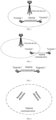
- FIG. 1 to FIG. 5 show system frameworks from a vehicle-mounted terminal to a vehicle-mounted terminal according to this application.
- all terminals in the sidelink communication within network coverage, all terminals (including a terminal 1 and a terminal 2) that perform sidelink communication are in coverage of a network device.
- all terminals may perform sidelink communication based on a same sidelink configuration by receiving configuration signaling from the network device.
- some terminals that perform sidelink communication are located in coverage of a network device. These terminals (namely, a terminal 1) can receive configuration signaling from the network device, and perform sidelink communication according to a configuration of the network device. However, a terminal (namely, a terminal 2) located outside the network coverage cannot receive configuration signaling from the network device. In this case, the terminal outside the network coverage determines, based on pre-configuration (pre-configuration) information and information carried in a physical sidelink broadcast channel (Physical Sidelink Broadcast Channel, PSBCH) transmitted by the terminals located in the network coverage, a sidelink configuration for sidelink communication.
- pre-configuration Physical Sidelink Broadcast Channel
- all terminals including a terminal 1 and a terminal 2 that perform sidelink communication are located outside network coverage, and all terminals perform sidelink communication according to a sidelink configuration determined based on pre-configuration information.
- a plurality of terminals (including a terminal 1, a terminal 2, and a terminal 3) form a communication group, and the communication group has a central control node, which may also be referred to as a cluster header (Cluster Header, CH).
- the central control node has one of following functions: responsible for establishment of the communication group; joining and leaving of a group member; resource coordination, allocation of sidelink transmission resources for another terminal, and reception of sidelink feedback information from the another terminal; resource coordination with another communication group; and other functions.
- the terminal 1 shown in FIG. 4 is a central control node in a communication group formed by the terminal 1, the terminal 2, and the terminal 3.
- Device-to-device communication is a sidelink (Sidelink, SL) transmission technology based on D2D.
- SL Sidelink
- D2D direct communication is adopted, which therefore has higher spectral efficiency and lower transmission latency.
- Two transmission modes are defined in 3GPP: Mode 1 and Mode 2.
- Transmission resources of a terminal are allocated by a network device, and the terminal transmits data on a sidelink based on the resources allocated by the network device.
- the network device may allocate, to the terminal, a resource for single transmission, or may allocate, to the terminal, a resource for semi-static transmission.
- a terminal is located in the network coverage, and a network allocates, to the terminal, a transmission resource used for sidelink transmission.
- a terminal selects a resource from a resource pool for data transmission.
- a terminal is located outside coverage of a cell, and the terminal independently selects a transmission resource from a pre-configured resource pool for sidelink transmission.
- a terminal independently selects a transmission resource from a resource pool configured by a network to perform sidelink transmission.
- LTE-V2X broadcast transmission is supported.
- NR-V2X unicast and multicast transmissions are introduced.
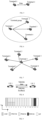
- FIG. 5 is a schematic diagram of unicast transmission according to this application. As shown in FIG. 5 , unicast transmission is performed between a terminal 1 and a terminal 2.
- FIG. 6 is a schematic diagram of multicast transmission according to this application. As shown in FIG. 6 , a terminal 1, a terminal 2, a terminal 3, and a terminal 4 form a communication group, where the terminal 1 transmits data, and other terminal devices in the group are all receiving terminals.
- FIG. 7 is a schematic diagram of broadcast transmission according to this application. As shown in FIG. 7 , a terminal 1 is a transmitting terminal, other terminals, namely, a terminal 2 to a terminal 6, around the terminal 1 are all receiving terminals.
- a sidelink feedback channel is introduced.
- FIG. 8 is a schematic diagram of sidelink feedback according to this application.
- a transmitting terminal transmits sidelink data (including a physical sidelink control channel (Physical Sidelink Control Channel, PSCCH) and a physical sidelink shared channel (Physical Sidelink Shared Channel, PSSCH)) to a receiving terminal, the receiving terminal transmits hybrid automatic repeat request (Hybrid Automatic Repeat reQuest, HARQ) feedback information (including acknowledgement (Acknowledgement, ACK) or negative acknowledgement (Negative Acknowledgement, NACK)) to the transmitting terminal, and the transmitting terminal determines, based on the feedback information from the receiving terminal, whether retransmission needs to be performed.
- the HARQ feedback information is carried on a sidelink feedback channel, for example, a PSFCH.
- sidelink feedback may be activated or deactivated by using pre-configuration information or network configuration information, or sidelink feedback may be activated or deactivated by a transmitting terminal. If the sidelink feedback is activated, the receiving terminal receives sidelink data sent by the transmitting terminal, and feeds back ACK or NACK to the transmitting terminal based on a detection result. The transmitting terminal determines, based on feedback information from the receiving terminal, to transmit retransmission data or new data. If the sidelink feedback is deactivated, the receiving terminal does not need to transmit feedback information, and the transmitting terminal generally transmits data in a blind retransmission manner. For example, the transmitting terminal repeatedly transmits each piece of sidelink data K times, instead of determining, based on feedback information from the receiving terminal, to transmit retransmission data.
- a sidelink feedback channel PSFCH In NR-V2X, a sidelink feedback channel PSFCH is introduced.
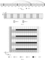
- the PSFCH carries 1-bit hybrid automatic repeat request acknowledgement (Hybrid Automatic Repeat request Acknowledgement, HARQ-ACK) information, occupies two time domain symbols in time domain (the second symbol carries sidelink feedback information, and data on the first symbol is replication of data on the second symbol.
- HARQ-ACK Hybrid Automatic Repeat request Acknowledgement
- the symbol is generally used as automatic gain control (Automatic gain control, AGC) at a receiving terminal), and occupies one resource block (resource block, RB) in frequency domain.
- AGC Automatic gain control
- FIG. 9 is a schematic diagram of a slot structure of a PSFCH and a PSCCH/PSSCH according to this application.
- one slot may include time domain symbols occupied by a PSFCH, a PSCCH, and a PSSCH.
- the last symbol is used as a guard period (Guard Period, GP)
- the last-but-one symbol is used for PSFCH transmission
- data on the last-but-two symbol is the same as data of a PSFCH symbol and used as AGC
- the last-but-three symbol is also used as GP.
- Data on the first symbol in the slot is the same as data on the second time domain symbol in the slot, and generally used as AGC.
- the PSCCH occupies three time domain symbols, and a remaining symbol may be used for PSSCH transmission. It should be understood that the figure only schematically shows time domain symbol information occupied by a PSFCH channel and a PSCCH/PSSCH channel in one slot, and does not reflect a relationship between frequency domain resources occupied by different channels.
- FIG. 10 is a schematic diagram of a resource of a sidelink feedback channel according to this application.
- An unlicensed spectrum is a spectrum that is classified by a country and a region and that can be used for communication of a radio device.
- the spectrum is generally considered as a shared spectrum, that is, a communications device in different communications systems can use the spectrum provided that a regulatory requirement set for the spectrum by a country or a region is met, and there is no need to apply for a dedicated spectrum grant to a government.
- a communications device follows a rule of "listen before talk (Listen Before Talk, LBT)", that is, before the communications device transmits a signal on a channel in an unlicensed spectrum, channel listening needs to be performed first, and the communications device can perform signal transmission only when a channel listening result is that the channel is idle; if the channel listening result of the communications device on the channel of the unlicensed spectrum is that the channel is busy, the communications device cannot perform signal transmission.
- LBT Listen Before Talk
- SL-U system a sidelink transmission system (referred to as an SL-U system) based on an unlicensed spectrum is studied.
- Communication on an unlicensed spectrum generally needs to meet a corresponding regulatory requirement.
- a range of a frequency band occupied by the terminal needs to be greater than or equal to 80% of system bandwidth. Therefore, in order to enable more users to access a channel in a same time as possible, an interlace (interlace)-based resource configuration manner is introduced in this application.
- One interlace includes N RBs, and a total of M interlaces are included in a frequency band range.
- the m th interlace includes ⁇ m, M+m, 2M+m, 3M+m, ... ⁇ .
- the interlace includes a plurality of resource blocks, which are referred to as interlaced resource blocks (Interlaced Resource Blocks, IRBs).
- IRBs Interlaced Resource Blocks
- a quantity of resource blocks between two consecutive interlaced resource blocks in one interlace is fixed as M, and a specific value of M is determined based on a subcarrier spacing. When the subcarrier spacing is 15 KHz, M is 10; when the subcarrier spacing is 30 KHz, M is 5.
- M interlaces may be orthogonally multiplexed in frequency domain, and the M interlace indexes range from 0 to M-1.
- interlace, the interlace resource, or the interlace index described in embodiments of this application may be replaced with each other, which is not limited in embodiments of this application.
- one interlace includes a plurality of RBs, which may be replaced with that one interlace resource includes a plurality of RBs, or one interlace index includes a plurality of RBs.
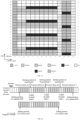
- FIG. 11 is an example of an interlace-based transmission resource according to an embodiment of this application.
- M the number of interlaces between two adjacent RBs
- each interlace may include six RBs.
- FIG. 12 and FIG. 13 are schematic diagrams of an interlace-based frame structure according to an embodiment of this application.
- FIG. 12 is a schematic diagram of a frame structure that includes only a PSCCH and a PSSCH and does not include a PSFCH in a slot; and
- FIG. 13 is a schematic diagram of a frame structure that includes a PSCCH, a PSSCH, and a PSFCH in a slot.
- Each interlace includes four RBs, where a digit on the left denotes an RB index, and a digit on the right denotes an interlace index.
- a system configures that the PSCCH occupies one interlace, and occupies two OFDM symbols in time domain.
- the PSSCH is in a unit of interlace. Data on the first symbol in the slot is the same as data on the second time domain symbol in the slot, and generally used as AGC.
- the last symbol is a GP symbol.
- a PSSCH 1 occupies an interlace 0 and an interlace 1
- a PSCCH 1 corresponding to the PSSCH 1 occupies the interlace 0, that is, a frequency domain starting position of the PSCCH and the PSSCH scheduled by the PSCCH is the same.
- FIG. 13 is a corresponding slot structure including a PSFCH resource.
- One PSFCH occupies one interlace, for example, a PSFCH 0 occupies an interlace 0, and occupies two time domain symbols in time domain. Data transmitted on two time domain symbols is the same. For example, data on the first symbol is a repetition of data on the second symbol, or data on the second symbol is a repetition of data on the first symbol.
- a symbol before the first time domain symbol occupied by the PSFCH is a GP symbol, and a symbol after the last time domain symbol occupied by the PSFCH is a GP symbol.
- data on the first time domain symbol shown in FIG. 12 and FIG. 13 may be a repetition of the data on the second symbol, and the symbol is generally used as AGC.
- FIG. 12 and FIG. 13 are merely examples in this application, and should not be construed as a limitation to this application.
- the frame structures shown in the figures may further include a resource occupied by second-stage sidelink control information (Sidelink Control Information, SCI) and a resource occupied by a PSCCH demodulation reference signal (Demodulation Reference Signal, DMRS) and a PSSCH DMRS.
- SCI second-stage sidelink control information
- DMRS Demodulation Reference Signal
- embodiments of this application provide a wireless communication method, a first terminal device, and a second terminal device, in which an interlace used to transmit a PSFCH is specified, so that system performance can be enhanced, and resource utilization can also be improved.
- a resource pool may be configured on an unlicensed spectrum or a shared spectrum by using pre-configuration information or network configuration information, and the resource pool may be used for sidelink transmission.
- the resource pool includes M1 resource block sets (Resource Block Set, RB set), one resource block set includes M2 resource blocks (Resource Block, RB), and M1 and M2 are positive integers.
- one resource block set corresponds to one channel (channel) on an unlicensed spectrum (or a shared spectrum), or one resource block set corresponds to a minimum frequency domain granularity for performing LBT, or one resource block set corresponds to an LBT sub-band.
- a bandwidth corresponding to a channel on an unlicensed spectrum is 20 MHz, that is, a bandwidth corresponding to one resource block set is also 20 MHz.
- a bandwidth of a channel on an unlicensed spectrum is 20 MHz, which is corresponding to M3 RBs.
- one resource block set corresponds to a quantity of RBs included in 20 MHz.
- the resource block set may also be referred to as a channel or an LBT sub-band, which is not limited in embodiments of this application.
- a frequency domain starting position of the resource pool is the same as a frequency domain starting position of a first resource block set in the M1 resource block sets, and the first resource block set may be a resource block set with the lowest frequency domain position in the M1 resource block sets.
- a frequency domain end position of the resource pool is the same as a frequency domain end position of a second resource block set in the M1 resource block sets, and the second resource block set may be a resource block set with the highest frequency domain position in the M1 resource block sets.
- FIG. 14 is an example of a resource pool configured on an unlicensed spectrum according to an embodiment of this application.
- a frequency domain position of the resource block set 0 is the lowest, and a frequency domain position of the resource block set 2 is the highest. Therefore, a frequency domain starting position of the resource pool is the same as a frequency domain starting position of the resource block set 0, or a frequency domain starting position of the resource pool is determined based on a frequency domain starting position of the resource block set 0.
- a frequency domain ending position of the resource pool is the same as a frequency domain ending position of the resource block set 2, or a frequency domain ending position of the resource pool is determined based on a frequency domain ending position of the resource block set 2.
- a guard band (Guard Band, GB) is included between two adjacent resource block sets in the M1 resource block sets included in the resource pool.
- a frequency domain starting position and a frequency domain size of the guard band may be determined based on pre-configuration information or network configuration information.
- a terminal device acquires pre-configuration information or network configuration information, and the pre-configuration information or network configuration information is used to configure a guard band (Guard Band, GB).
- the guard band is used to separate resource block sets (RB sets).
- a frequency domain starting position and ending position of each resource block set may be determined according to a frequency domain starting position of a sidelink BWP (namely, a starting position of the sidelink BWP shown in the figure) and a frequency domain starting position of each guard band (namely, a starting position of a guard band shown in the figure) and a frequency domain size of a guard band (namely, a length of a guard band shown in the figure).
- the resource pool includes three resource block sets, namely, a resource block set 0 to a resource block set 2, a frequency domain starting position of the resource pool (namely, a starting position of the resource pool shown in the figure) corresponds to the frequency domain starting position of the resource block set 0, and a frequency domain ending position of the resource pool (namely, an ending position of the resource pool shown in the figure) corresponds to the frequency domain ending position of the resource block set 2.
- one resource block set includes a plurality of interlaces.
- each resource block set from the resource block set 0 to the resource block set 2 may include a plurality of interlaces.
- one PSSCH may be transmitted in one or more resource block sets.
- one PSSCH may occupy a transmission resource in one or more resource block sets.
- one PSSCH may be transmitted in one or more resource block sets, and the one PSSCH occupies one or more interlaces in the one or more resource block sets.
- the resource pool includes three resource block sets, namely, a resource block set 0, a resource block set 1, and a resource block set 2.
- a size of subcarrier spacing is 15 kHz
- 100 RBs are included in one resource block set, and corresponding to 10 interlaces, namely, an interlace 0 to an interlace 9.
- One PSSCH may be transmitted in one resource block set. Further, the one PSSCH may occupy a resource corresponding to some or all interlaces in the resource block set.
- a PSSCH 1 is transmitted in the resource block set 0, and the PSSCH 1 occupies a resource corresponding to all interlaces in the resource block set 0, that is, the PSSCH 1 occupies a resource corresponding to the interlace 0 to the interlace 9 in the resource block set 0.
- a PSSCH 2 is transmitted in the resource block set 1, and the PSSCH 2 occupies a resource corresponding to two interlaces in the resource block set 1, for example, the PSSCH 2 occupies a resource corresponding to the interlace 0 and the interlace 1 in the resource block set 1.
- APSSCH 3 is transmitted in the resource block set 1 and the resource block set 2, and the PSSCH 3 separately occupies resources corresponding to three interlaces in the two resource block sets. For example, the PSSCH 3 separately occupies resources corresponding to the interlace 3, the interlace 4, and the interlace 5 in the resource block set 1 and the resource block set 2.
- FIG. 15 is a schematic flowchart of a wireless communication method 200 according to an embodiment of this application.
- the method 200 may be performed by a first terminal device.
- the first terminal device may be a receiving terminal for receiving a PSSCH.
- the first terminal device may be the terminal B mentioned above, or the first terminal device may be the terminal A mentioned above.
- S210 Receive a first physical sidelink shared channel PSSCH in a first slot.
- S220 Determine a first transmission resource from a PSFCH transmission resource set included in a second slot.
- S230 Transmit a first PSFCH on the first transmission resource.
- the second slot is determined based on the first slot, and the first PSFCH carries sidelink feedback information that is in response to the first PSSCH.
- the PSFCH transmission resource set is introduced based on the second slot, and the first PSFCH corresponding to the first PSSCH received in the first slot is designed to be transmitted on the first transmission resource determined in the PSFCH transmission resource set.
- the first terminal device may implement transmission of the first PSFCH based on the first transmission resource, thereby improving system performance.
- PSFCHs corresponding to PSSCHs in different slots may be multiplexed and transmitted in a same slot in a same manner, thereby improving resource utilization.
- the first PSFCH carries sidelink feedback information corresponding to the first PSSCH, and the sidelink feedback information includes ACK or NACK.
- a size of a frequency domain resource of the first PSFCH is a physical resource block.
- the first transmission resource in this application may include a time domain resource, a frequency domain resource, or a code domain resource.
- the second slot may be determined based on a first slot where the first PSSCH is located.
- the first terminal device may determine, based on a slot where the first PSSCH is located and a minimum time interval between a PSSCH and a PSFCH, a slot where the first PSFCH is located. For example, the minimum time interval between the PSSCH and the PSFCH is k slots. If the first terminal device receives the first PSSCH in a slot n, the slot where the first PSFCH is located, namely, the second slot, is the first slot that is located after slot n+k (including the slot n+k) and that includes a PSFCH transmission resource.
- the first PSSCH may also be replaced with another physical sidelink channel on which feedback needs to be performed, that is, the first PSSCH may be replaced with a first physical sidelink channel;
- the first PSFCH may also be replaced with any other physical sidelink channel that can carry feedback information, that is, the first PSFCH may be replaced with a second physical sidelink channel, and the second physical sidelink channel is used to carry feedback information corresponding to the first physical sidelink channel;
- the first slot and the second slot may be respectively replaced with time units of another granularity, that is, the first slot and the second slot may be respectively replaced with a first time unit and a second time unit.
- the first time unit includes but is not limited to a time domain time unit such as a frame, a subframe, a slot, and a symbol.
- the second time unit includes but is not limited to a time domain time unit such as a frame, a subframe, a slot, and a symbol.
- the first terminal device may receive the first physical sidelink channel on the first time unit, determine the first transmission resource from a transmission resource set included in the second time unit and used to transmit feedback information, and transmit, on the first transmission resource, feedback information corresponding to the first physical sidelink channel.
- the first physical sidelink channel may be a PSSCH.
- the feedback information may be carried on a second physical sidelink channel, and the second physical sidelink channel may be a PSFCH.
- the first time unit includes but is not limited to a time domain time unit such as a frame, a subframe, a slot, and a symbol.
- the second time unit includes but is not limited to a time domain time unit such as a frame, a subframe, a slot, and a symbol.
- the first PSSCH occupies at least one sub-channel (sub-channel).
- the step S220 may include: determining a first transmission resource set based on information about a resource block set where the first PSSCH is located and index information corresponding to a sub-channel occupied by the first PSSCH, where the first transmission resource set includes the first transmission resource, and the index information corresponding to the sub-channel occupied by the first PSSCH includes at least one of following information:
- one resource block set may include one or more sub-channels, and each sub-channel includes a plurality of RBs that are consecutive in frequency domain.
- one resource pool may include a plurality of resource block sets, and one resource block set may include a plurality of sub-channels.
- the first terminal device may determine, from the PSFCH transmission resource set included in the second slot, the first transmission resource set available for transmission of the first PSFCH based on the information about the resource block set where the first PSSCH is located and the index information corresponding to the sub-channel occupied by the first PSSCH.
- the first transmission resource set includes a frequency domain resource available for transmission of the first PSFCH and a code domain resource available for transmission of the first PSFCH.
- the frequency domain resource available for transmission of the first PSFCH is determined based on the information about the resource block set where the first PSSCH is located and/or the index information corresponding to the sub-channel occupied by the first PSSCH.
- the resource block set where the first PSSCH is located includes at least one first resource block set
- the first transmission resource set includes at least one second resource block set
- the at least one second resource block set is determined based on information about the at least one first resource block set.
- one resource pool may include a plurality of resource block sets, and the transmission resource of the first PSSCH may occupy one or more resource block sets. Therefore, when determining the first transmission resource, the first terminal device may determine, from the PSFCH transmission resource set included in the second slot and based on at least one first resource block set occupied by the first PSSCH, at least one second resource block set corresponding to the at least one first resource block set, and further may determine, from the at least one second resource block set, a frequency domain resource corresponding to the first PSFCH and a corresponding code domain resource.
- a PSFCH transmission resource may be configured in two manners:
- Each resource block set in the B resource block sets is configured with a corresponding PSFCH transmission resource.
- the PSFCH transmission resource includes a physical resource block available for transmission of a PSFCH.
- a same PSFCH transmission resource is configured for each resource block set in the B resource block sets.
- the first terminal device may determine, based on information about at least one first resource block set where the first PSSCH is located, information about at least one second resource block set used to transmit the first PSFCH. Further, the first terminal device may determine, based on index information corresponding to a sub-channel occupied by the first PSSCH in the at least one first resource block set, information about a physical resource block in at least one corresponding second resource block set.
- Only one group of physical resource blocks available for transmission of a PSFCH is configured during configuration of a PSFCH transmission resource. For example, when determining a transmission resource of the first PSFCH based on the transmission resource of the first PSSCH, the first terminal device may determine information about a corresponding physical resource block from a physical resource block set available for transmission of a PSFCH based on information about at least one first resource block set where the first PSSCH is located and index information corresponding to a sub-channel occupied by the first PSSCH.
- a parameter sl-PSFCH-RB-Set in resource pool configuration information is used to configure a physical resource block set available for transmission of the PSFCH.
- each resource block set has a corresponding parameter sl-PSFCH-RB-Set, or the resource pool configuration information includes only one parameter sl-PSFCH-RB-Set.
- a physical resource block set configured by using the parameter is applicable to each resource block set in the B resource block sets.
- the resource pool configuration information includes only one parameter sl-PSFCH-RB-Set, and a PSFCH transmission resource corresponding to the PSSCH transmitted in the A resource block sets is located in a physical resource block set indicated by the parameter sl-PSFCH-RB-Set.
- the first terminal device may further determine a first transmission resource set (one transmission resource includes a frequency domain resource and a code domain resource) based on code domain resource information (or cyclic shift pair information) supported in one physical resource block, and then the first terminal device may determine a specific transmission resource in the first transmission resource set based on identities of a transmitting terminal and a receiving terminal.
- a first transmission resource set one transmission resource includes a frequency domain resource and a code domain resource
- code domain resource information or cyclic shift pair information
- the method 200 may further include:
- transmission resources included in the first transmission resource set are indexed in following order: indexing first according to a frequency domain resource, and then according to a code domain resource.
- FIG. 16 shows an example of an index of a transmission resource set available for transmission of a PSFCH according to an embodiment of this application.
- a range of indexes of the N ⁇ frequency domain resources is 0, 1, ..., N f -1
- each of the N ⁇ frequency domain resources supports Ncs cyclic shift pairs
- a range of index values of the Ncs cyclic shift pairs is 0, 1, ..., Ncs-1.
- an ascending resource index order of the transmission resources in the first transmission resource set corresponds to an order that is indexed first in an ascending order of frequency domain resources, and then in an ascending order of cyclic shift pairs.
- the cyclic shift pair in this application may also be referred to as a code domain resource.
- the indexing first according to a frequency domain resource includes: indexing first according to an ascending order of a resource block set index, and then according to an ascending order of a physical resource block index; or indexing first according to an ascending order of a physical resource block index, and then according to an ascending order of a resource block set index.
- the N ⁇ frequency domain resources may be physical resource blocks obtained by indexing first according to an ascending order of a resource block set index, and then according to an ascending order of a physical resource block index; or the N ⁇ frequency domain resources may be physical resource blocks obtained by indexing first according to an ascending order of a physical resource block index, and then according to an ascending order of a resource block set index.
- N CS may denote a quantity of cyclic shift pairs supported in one resource block.
- the method 200 may further include: determining the first transmission resource in the first transmission resource set based on identity information of the first terminal device and/or identity information of a second terminal device, where the second terminal device is a terminal device that transmits the first PSSCH.
- the first terminal device may determine the first transmission resource from a first transmission resource set available for transmission of the first PSFCH based on identity information of a transmitting terminal of the first PSFCH (corresponding to a receiving terminal of the first PSSCH) and identity information of a receiving terminal of the first PSFCH (corresponding to a transmitting terminal of the first PSSCH).
- S denotes an index of the first transmission resource
- P ID denotes the identity of the second terminal device
- M ID denotes the identity of the first terminal device
- N total denotes a quantity of PSFCH transmission resources included in the first transmission resource set
- mod denotes a modulo operation
- the identity information of the first terminal device is determined based on a member identity of the first terminal device in a communication group, or the identity information of the first terminal device is 0.
- the identity information of the first terminal device is the member identity of the first terminal device in a communication group.
- the identity information of the first terminal device is determined based on a member ID (member identity) of the first terminal device in a communication group; for the multicast communication, when the first terminal device feeds back only NACK (namely, a NACK-only feedback manner), the identity information of the first terminal device is 0; and for unicast communication, the identity information of the first terminal device is 0.
- the identity information of the first terminal device may alternatively be set to another value, which is not limited in this application.
- the identity information of the second terminal device is determined based on source identity information carried in sidelink control information SCI corresponding to the first PSSCH.
- the identity information of the second terminal device is source identity information carried in sidelink control information SCI corresponding to the first PSSCH.
- the identity information of the second terminal device is determined based on the source identity information carried in the SCI associated with the first PSSCH, and the identity information of the first terminal device is determined based on identity information of a group member of the first terminal device, or the identity information of the first terminal device is 0.
- the first PSSCH occupies at least one first interlace.
- the S220 may include: determining a second transmission resource set in the second slot based on at least one of following information:
- the second transmission resource set includes the first transmission resource.
- one resource block set may include one or more interlaces, and each interlace includes a plurality of RBs that are discrete in frequency domain.
- a resource pool may include a plurality of resource block sets, and a resource block set may include one or more interlaces.
- the first terminal device may determine, from the PSFCH transmission resource set included in the second slot, the second transmission resource set available for transmission of the first PSFCH based on at least one of following information:
- the second transmission resource set may include a frequency domain resource and a code domain resource
- the frequency domain resource in the second transmission resource set may include a resource block set available for transmission of the first PSFCH and an interlace available for transmission of the first PSFCH.
- the interlace available for transmission of the first PSFCH may be an interlace in a resource block set available for transmission of the first PSFCH.
- the code domain resource in the second transmission resource set may include a code domain resource available for transmission of the first PSFCH in one interlace or a code domain resource available for transmission of the first PSFCH in one resource block.
- the code domain resource in the second transmission resource set may include a code domain resource available for transmission of the first PSFCH in one interlace available for transmission of the first PSFCH, or the code domain resource in the second transmission resource set may include a code domain resource available for transmission of the first PSFCH in one resource block available for transmission of the first PSFCH.
- information used to determine the frequency domain resource in the second resource set may include: information used to determine the resource block set available for transmission of the first PSFCH; and information used to determine an interlace available for transmission of the first PSFCH.
- Information used to determine the code domain resource of the second transmission resource set may include information used to determine, in one interlace or one resource block, a code domain resource available for transmission of the first PSFCH.
- the information about the at least one first interlace includes at least one of following information:
- the transmission resources included in the second transmission resource set are indexed in following order: indexing first according to a frequency domain resource, and then according to a code domain resource.
- N total NrNcs, that is, including N ⁇ frequency domain resources.
- a range of indexes of the N ⁇ frequency domain resources is 0, 1, ..., N f -1.
- Each frequency domain resource (including one interlace or one physical resource block) of the N ⁇ frequency domain resources supports Ncs cyclic shift pairs, and a range of index values of the Ncs cyclic shift pairs is 0, 1, ..., Ncs-1.
- an ascending resource index order of the transmission resources in the second transmission resource set corresponds to an order that is indexed first in an ascending order of frequency domain resources, and then in an ascending order of cyclic shift pairs.
- the cyclic shift pair in this application may also be referred to as a code domain resource.
- the indexing first according to a frequency domain resource includes: indexing first according to an ascending order of a resource block set index, and then according to an ascending order of an interlace index; or indexing first according to an ascending order of an interlace index, and then according to an ascending order of a resource block set index.
- the N ⁇ frequency domain resources may be interlaces obtained by indexing first according to an ascending order of a resource block set index, and then according to an ascending order of an interlace index; or the N ⁇ frequency domain resources may be interlaces obtained by indexing first according to an ascending order of an interlace index, and then according to an ascending order of a resource block set index.
- the resource block set where the first PSSCH is located includes at least one third resource block set
- the second transmission resource set includes at least one fourth resource block set
- the at least one fourth resource block set is determined based on information about the at least one third resource block set.
- a resource pool may include a plurality of resource block sets, and a resource block set may include one or more interlaces.
- the first terminal device may determine, from the PSFCH transmission resource set included in the second slot and based on at least one third resource block set occupied by the first PSSCH, at least one fourth resource block set corresponding to the at least one third resource block set. Further, the first terminal device may determine, from the at least one fourth resource block set, at least one second interlace available for transmission of the first PSFCH and a corresponding code domain resource.
- the code domain resource in this application may be a code domain resource supported in one resource block, or may be a code domain resource supported in one interlace. This is not limited in this application.
- the method 200 may further include: determining the at least one fourth resource block set based on index information corresponding to the at least one third resource block set, where the index information corresponding to the at least one third resource block set includes at least one of following information:
- the second transmission resource set includes at least one second interlace, and the second interlace is determined based on at least one of following information:
- the at least one second interlace may be determined from the PSFCH transmission resource set based on the information about the at least one first interlace.
- an interlace occupied by the first PSSCH may correspond to an interlace of the first PSFCH, that is, an interlace where a transmission resource of the first PSSCH is located and an interlace where a transmission resource of the first PSFCH is located may correspond to each other. That is to say, the interlace where the transmission resource of the first PSFCH is located may be determined based on the interlace where the transmission resource of the first PSSCH is located.
- the interlace where the transmission resource of the first PSFCH is located may be determined based on an interlace index corresponding to a frequency domain starting position of the transmission resource of the first PSSCH, or the interlace where the transmission resource of the first PSFCH is located may be determined based on an index of all interlaces corresponding to the transmission resource of the first PSSCH.
- the second transmission resource set includes the at least one second interlace in each of the at least one fourth resource block set.
- the information about the at least one first interlace includes at least one of following:
- the information about the at least one first interlace may also be referred to as information about the first interlace occupied by the first PSSCH. That is to say, the information about the at least one first interlace includes at least one of following:
- an index of the at least one second interlace may be determined based on an index of the first first interlace in the at least one first interlace. For example, if the first PSSCH occupies an interlace 0 and an interlace 1, the index of the at least one second interlace is determined based on the interlace 0. For example, the index of the first first interlace in the at least one first interlace is determined as the index of the at least one second interlace, that is, the index of the at least one second interlace is the interlace 0.
- the index of the at least one second interlace may be determined based on indexes of all interlaces in the at least one first interlace. For example, if the first PSSCH occupies an interlace 0 and an interlace 1, the index of the at least one second interlace is determined based on the interlace 0 and the interlace 1. For example, the indexes of all interlaces in the at least one first interlace are determined as the index of the at least one second interlace, that is, the index of the at least one second interlace includes the interlace 0 and the interlace 1.
- the first PSSCH occupies N 1 interlace
- a PSSCH resource pool includes N 4 interlaces
- a PSFCH slot includes N 5 interlaces
- N 4 K 1 ⁇ N 5 , and K 1 are positive integers
- every K 1 first interlaces in the PSSCH slot are corresponding to one interlace in the PSFCH slot.
- N 5 K 2 ⁇ N 4 , and K 2 are positive integers
- one first interlace in the PSSCH slot is corresponding to K 2 interlaces in the PSFCH slot.
- a second interlace resource used to transmit a PSFCH may be determined based on information about a first interlace occupied by a PSSCH.
- the quantity N 4 of interlaces included in the PSSCH resource pool and the quantity N 5 of interlaces included in the PSFCH slot are determined by using resource pool configuration information.
- N 4 is an integer multiple of N 5
- N 5 is an integer multiple of N 4 . That is, a quantity of interlaces in the PSSCH resource pool configured by using the resource pool configuration information may be exactly divided by a quantity of interlaces included in the PSFCH slot, or a quantity of interlaces included in the PSFCH slot configured by using the resource pool configuration information may be exactly divided by a quantity of interlaces in the PSSCH resource pool.
- an interlace in a resource pool where a PSSCH is located there is a correspondence between an interlace in a resource pool where a PSSCH is located and an interlace used to transmit a PSFCH.
- one interlace in the resource pool where the PSSCH is located may correspond to one interlace used to transmit the PSFCH, or a plurality of interlaces in the resource pool where the PSSCH is located may correspond to one interlace used to transmit the PSFCH, or one interlace in the resource pool where the PSSCH is located may correspond to a plurality of interlaces used to transmit the PSFCH.
- an interlace resource corresponding to the first PSFCH and associated with the first PSSCH may be determined based on an interlace resource occupied by the first PSSCH.
- the PSSCH resource pool includes N 4 interlaces, and a transmission resource available for transmission of the PSFCH in the PSFCH slot includes N 5 interlaces.
- Each interlace in the PSSCH resource pool has a corresponding interlace in the PSFCH slot. If the first PSSCH occupies N 1 interlaces, N 3 interlaces corresponding to the N 1 interlaces may be determined in the PSFCH slot.
- a transmission resource, associated with the first PSSCH, of the first PSFCH is located in the N 3 interlaces, where N 1 , N 3 , N 4 , and N 5 are positive integers.
- an interlace X in the PSSCH slot corresponds to an interlace Y in the PSFCH slot, which represents that an available transmission resource of a PSFCH that corresponds to a PSSCH transmitted on the interlace X in the PSSCH slot includes the interlace Y in the PSFCH slot;
- an interlace X and an interlace Y in the PSSCH slot are corresponding to an interlace Z in the PSFCH slot, which represents that an available transmission resource of a PSFCH that corresponds to a PSSCH transmitted on the interlace X in the PSSCH slot and/or on the interlace Y in the PSSCH slot includes the interlace Z in the PSFCH slot;
- an interlace X in the PSSCH slot corresponds to an interlace Y and an interlace Z in the PSFCH slot, which represents that an available transmission resource of a PSFCH that corresponds to a PSSCH transmitted on the interlace X in the PSSCH slot includes the interlace Y and/or the interlace Z in the PSFCH slot, where X, Y
- the first PSSCH may occupy N 1 interlaces, and a size of N 1 is related to a size of a transport block corresponding to sidelink data carried in the first PSSCH.
- an interlace included in the PSSCH resource pool and an interlace in the PSFCH slot may be in a one-to-one correspondence, or may be in a many-to-one correspondence, or may be in a one-to-many correspondence, which is not limited in this application.
- an interlace included in the PSSCH resource pool and an interlace in the PSFCH slot are a one-to-one correspondence.
- FIG. 17 shows an example in which there is a one-to-one correspondence between an interlace included in a PSSCH resource pool and an interlace in a PSFCH slot according to an embodiment of this application.
- PSSCH transmission resources include a slot 7 to a slot 10 in time domain, and an interlace 0 to an interlace 3 in frequency domain.
- PSFCH transmission resources include an interlace 0 to an interlace 3 in a slot 12.
- PSFCHs corresponding to PSSCHs transmitted in the slot 7 to the slot 10 are all transmitted in the slot 12, that is to say, PSSCH slots associated with a PSFCH slot 12 include the slot 7 to the slot 10.
- interlace resources shown in the figure belong to one resource block set.
- the interlace resources shown in the figure may be interlace resources included in any resource block set.
- a structure of interlace resources in any resource block set in a resource pool is shown in FIG. 17 .
- an interlace where a transmission resource of a PSSCH is located there is a one-to-one correspondence between an interlace where a transmission resource of a PSSCH is located and an interlace where a transmission resource, of a PSFCH corresponding to the PSSCH, is located. That is, for a PSSCH transmitted on the interlace 0 and in the slot 7 to the slot 10, an available transmission resource of a PSFCH corresponding to the PSSCH includes the interlace 0 of the slot 12. For a PSSCH transmitted on the interlace 1 and in the slot 7 to the slot 10, an available transmission resource of a PSFCH corresponding to the PSSCH includes the interlace 1 of the slot 12.
- an available transmission resource of a PSFCH corresponding to the PSSCH includes the interlace 2 of the slot 12.
- an available transmission resource of a PSFCH corresponding to the PSSCH includes the interlace 3 of the slot 12.
- the second slot is determined based on a first slot where the first PSSCH is located.
- a slot where a transmission resource of the first PSSCH is located is a slot from the slot 7 to the slot 10
- a PSFCH period P is set to four slots
- a minimum time interval between a PSSCH and a PSFCH is two slots.
- the second slot is the slot 12, that is, a slot including a transmission resource of the PSFCH is the slot 12.
- interlaces in each PSSCH slot include an interlace 0, an interlace 1, an interlace 2, and an interlace 3, and the PSFCH slot (that is, interlaces corresponding to the second slot) includes the interlace 0, the interlace 1, the interlace 2, and the interlace 3.
- the at least one second interlace may also include the interlace 1.
- FIG. 18 shows an example in which there is a many-to-one correspondence between an interlace included in a PSSCH resource pool and an interlace in a PSFCH slot according to an embodiment of this application.
- PSSCH transmission resources include a slot 7 to a slot 10 in time domain, and an interlace 0 to an interlace 3 in frequency domain.
- PSFCH transmission resources include an interlace 0 to an interlace 1 in a slot 12.
- PSFCHs corresponding to PSSCHs transmitted in the slot 7 to the slot 10 are all transmitted in the slot 12, that is to say, PSSCH slots associated with a PSFCH slot 12 include the slot 7 to the slot 10.
- interlace resources shown in the figure belong to one resource block set.
- the interlace resources shown in the figure may be interlace resources included in any resource block set.
- a structure of interlace resources in any resource block set in a resource pool is shown in FIG. 18 .
- an available transmission resource of a PSFCH corresponding to the PSSCH includes the interlace 0 of the slot 12.
- an available transmission resource of a PSFCH corresponding to the PSSCH includes the interlace 1 of the slot 12.
- the second slot is determined based on a first slot where the first PSSCH is located.
- a slot where a transmission resource of the first PSSCH is located is a slot from the slot 7 to the slot 10
- a PSFCH period P is set to four slots
- a minimum time interval between a PSSCH and a PSFCH is two slots.
- the second slot is the slot 12, that is, a slot including a transmission resource of the PSFCH is the slot 12.
- interlaces in each PSSCH slot include an interlace 0, an interlace 1, an interlace 2, and an interlace 3, and the PSFCH transmission resource set (namely, interlaces corresponding to the second slot) includes the interlace 0 and the interlace 1.
- the at least one second interlace may include the interlace 0.
- FIG. 19 shows an example in which there is a one-to-many correspondence between an interlace included in a PSSCH resource pool and an interlace in a PSFCH slot according to an embodiment of this application.
- PSSCH transmission resources include a slot 7 to a slot 10 in time domain, and an interlace 0 and an interlace 1 in frequency domain.
- PSFCH transmission resources include an interlace 0 to an interlace 3 in a slot 12.
- PSFCHs corresponding to PSSCHs transmitted in the slot 7 to the slot 10 are all transmitted in the slot 12, that is to say, PSSCH slots associated with a PSFCH slot 12 include the slot 7 to the slot 10.
- interlace resources shown in the figure belong to one resource block set.
- the interlace resources shown in the figure may be interlace resources included in any resource block set.
- a structure of interlace resources in any resource block set in a resource pool is shown in FIG. 19 .
- an available transmission resource of a PSFCH corresponding to the PSSCH includes the interlace 0 and the interlace 1 of the slot 12.
- an available transmission resource of a PSFCH corresponding to the PSSCH includes the interlace 2 and the interlace 3 of the slot 12.
- an available transmission resource of a PSFCH corresponding to the PSSCH includes the interlace 2 and the interlace 3 of the slot 12.
- transmission resources of a PSFCH corresponding to the PSSCH include the interlace 0, the interlace 1, the interlace 2, and the interlace 3.
- the second slot is determined based on a first slot where the first PSSCH is located.
- a slot where a transmission resource of the first PSSCH is located is a slot from the slot 7 to the slot 10
- a PSFCH period P is set to four slots
- a minimum time interval between a PSSCH and a PSFCH is two slots.
- the second slot is the slot 12, that is, a slot including a transmission resource of the PSFCH is the slot 12.
- interlaces in each PSSCH slot include an interlace 0 and an interlace 1
- the PSFCH transmission resource set (namely, interlaces corresponding to the second slot) includes an interlace 0, an interlace 1, an interlace 2, and an interlace 3.
- the at least one second interlace may include the interlace 0 and the interlace 1.
- the at least one second interlace is determined based on the at least one first interlace and the first slot.
- PSSCH transmission resources include a slot 7 to a slot 10 in time domain, and an interlace 0 and an interlace 1 in frequency domain.
- PSFCH transmission resources include an interlace 0 to an interlace 3 in a slot 12.
- PSFCHs corresponding to PSSCHs transmitted in the slot 7 to the slot 10 are all transmitted in the slot 12, that is to say, PSSCH slots associated with a PSFCH slot 12 include the slot 7 to the slot 10.
- interlace resources shown in the figure belong to one resource block set.
- the interlace resources shown in the figure may be interlace resources included in any resource block set.
- a structure of interlace resources in any resource block set in a resource pool is shown in FIG. 19 .
- transmission resources of PSFCHs corresponding to PSSCHs transmitted in different PSSCH slots may correspond to different interlaces in the PSFCH slot.
- a transmission resource of a PSFCH corresponding to a PSSCH transmitted on the interlace 0 of the slot 7 includes the interlace 0 of the slot 12; a transmission resource of a PSFCH corresponding to a PSSCH transmitted on the interlace 1 of the slot 7 includes the interlace 1 of the slot 12; a transmission resource of a PSFCH corresponding to a PSSCH transmitted on the interlace 0 of the slot 8 includes the interlace 2 of the slot 12; a transmission resource of a PSFCH corresponding to a PSSCH transmitted on the interlace 1 of the slot 8 includes the interlace 3 of the slot 12; a transmission resource of a PSFCH corresponding to a PSSCH transmitted on the interlace 0 of the slot 9 includes the interlace 0 of the slot 12; a transmission resource of a PSFCH corresponding to a PSSCH transmitted on the interlace 1 of the slot 9 includes the interlace 1 of the slot 12; a transmission resource of a PSFCH corresponding to a PSSCH transmitted on the interlace 0 of the slot
- transmission resources of PSFCHs corresponding to PSSCHs transmitted in the slot 7 and the slot 8 are corresponding to different interlaces in the slot 12, that is, PSFCHs corresponding to PSSCHs transmitted in the slot 7 and the slot 8 are frequency division multiplexed in the slot 12; and transmission resources of PSFCHs corresponding to PSSCHs transmitted in the slot 9 and the slot 10 are corresponding to different interlaces in the slot 12, that is, PSFCHs corresponding to PSSCHs transmitted in the slot 9 and the slot 10 are frequency division multiplexed in the slot 12.
- transmission resources of PSFCHs corresponding to PSSCHs transmitted on a same interlace in the slot 7 and the slot 9 are corresponding to a same interlace in the slot 12.
- different code domain resource sets may be determined in the same interlace, so that transmission resources of PSFCHs corresponding to PSSCHs transmitted on a same interlace in the slot 7 and the slot 9 are code division multiplexed in the slot 12; and transmission resources of PSFCHs corresponding to PSSCHs transmitted on a same interlace in the slot 8 and the slot 10 are corresponding to a same interlace in the slot 12. Further, different code domain resource sets may be determined in the same interlace, so that transmission resources of PSFCHs corresponding to PSSCHs transmitted on a same interlace in the slot 8 and the slot 10 are code division multiplexed in the slot 12.
- transmission resources of PSFCHs corresponding to PSSCHs transmitted in different PSSCH slots may be frequency division multiplexed or code division multiplexed in the PSFCH slot, and interlace resources, in the PSFCH slot, of the PSFCHs corresponding to the PSSCHs may be determined based on information of slots where the PSSCHs are located and information about interlaces occupied by the PSSCHs.
- FIG. 17 to FIG. 19 are merely examples of this application, and should not be construed as a limitation to this application.
- one interlace in FIG. 17 to FIG. 19 includes one RB.
- a plurality of RBs included in one interlace should be evenly distributed in a frequency domain range. Details are not described in this application.
- FIG. 17 to FIG. 19 show examples in which a frequency domain resource in one slot includes four or two interlaces.
- a frequency domain resource in one slot may alternatively include another quantity of interlaces.
- FIG. 17 to FIG. 19 are merely examples of this application, and should not be construed as a limitation to this application.
- one interlace in FIG. 17 to FIG. 19 includes one RB.
- a plurality of RBs included in one interlace should be evenly distributed in a frequency domain range. Details are not described in this application.
- FIG. 17 to FIG. 19 show examples in which a frequency domain resource in one slot includes four or two interlaces.
- FIG. 17 shows that one interlace where a PSSCH transmission resource is located corresponds to one interlace in a PSFCH slot, that is, there is a one-to-one correspondence between an interlace where a PSFCH transmission resource is located and an interlace where a PSSCH transmission resource is located.
- FIG. 18 shows that two interlaces where PSSCH transmission resources are located correspond to one interlace in the PSFCH slot, that is, one interlace where a PSFCH transmission resource is located corresponds to two interlaces where the PSSCH transmission resources are located.
- FIG. 19 shows that one interlace where a PSSCH transmission resource is located corresponds to two interlaces in a PSFCH slot, that is, two interlaces where PSFCH transmission resources are located correspond to one interlace where the PSSCH transmission resource is located.
- the second transmission resource set includes a first code domain resource set, and the first code domain resource set is determined based on at least one of following information:
- the first code domain resource set may be a code domain resource set corresponding to one interlace (for example, an interlace used to transmit a PSSCH).
- the first PSSCH occupies at least one first interlace in at least one third resource block set
- the first PSFCH occupies at least one second interlace in at least one fourth resource block set
- the first code domain resource set includes a code domain resource, in one second interlace, corresponding to one first interlace in the at least one first interlace.
- the first code domain resource set includes a code domain resource, in one second interlace in a PSFCH slot, corresponding to one first interlace in a PSSCH slot.
- the first code domain resource set includes a code domain resource, in one second interlace in the second slot, corresponding to one first interlace in the first slot.
- the first code domain resource set includes a code domain resource, in one second interlace, corresponding to one first interlace in the at least one first interlace.
- the first code domain resource set is a code domain resource set corresponding to one interlace in the at least one fourth resource block set.
- the first code domain resource set may be a code domain resource set corresponding to a slot (for example, a slot used to transmit a PSSCH).
- the first PSSCH occupies at least one first interlace in the at least one third resource block set
- the first PSFCH occupies at least one second interlace in the at least one fourth resource block set
- the first code domain resource set includes a code domain resource, corresponding to the first slot, in one second interlace in the at least one second interlace.
- the first code domain resource set includes a code domain resource, in one second interlace in a PSFCH slot, corresponding to a first slot where the first PSSCH is located.
- the first code domain resource set includes a code domain resource, corresponding to the first slot, in one second interlace in the second slot.
- the first PSSCH occupies at least one first resource block of at least one first interlace in the at least one third resource block set
- the first PSFCH occupies at least one second resource block of at least one second interlace in the at least one fourth resource block set.
- the first code domain resource set includes a code domain resource, corresponding to the first slot, in one second resource block of the at least one second resource block.
- the first code domain resource set includes a code domain resource, in one second resource block in a PSFCH slot, corresponding to a first slot where the first PSSCH is located.
- the first code domain resource set includes a code domain resource, corresponding to the first slot, in one second resource block in the second slot.
- the first code domain resource set may be a code domain resource set corresponding to one resource block (for example, one resource block in one interlace used to transmit a PSSCH).
- the first PSSCH occupies at least one first resource block of at least one first interlace in the at least one third resource block set
- the first PSFCH occupies at least one second resource block of at least one second interlace in the at least one fourth resource block set.
- the first code domain resource set includes a code domain resource, in one second resource block, corresponding to one first resource block of the at least one first resource block.
- the first code domain resource set includes a code domain resource, in one second resource block in a PSFCH slot, corresponding to one first resource block in a PSSCH slot.
- the first code domain resource set includes a code domain resource, in one second resource block in the second slot, corresponding to one first resource block in the first slot.
- the first code domain resource set includes a code domain resource, in one second resource block, corresponding to one first resource block of the at least one first resource block.
- the first code domain resource set is a code domain resource set, of one resource block in one interlace, in the at least one fourth resource block set.
- the first code domain resource set may be a code domain resource set corresponding to one interlace, one slot, or even one resource block
- a frequency domain resource and a code domain resource of one transmission resource in the second transmission resource set are definite.
- different transmission resources in the second transmission resource set have different code domain resources and/or different frequency domain resources, which is equivalent to that, in this embodiment, one PSFCH in a slot including a PSFCH transmission resource may correspond to PSSCHs transmitted in P slots. That is, in this embodiment, PSFCHs corresponding to PSSCHs in a plurality of slots can be carried in one slot, so as to implement frequency division multiplexing and/or code division multiplexing on the PSFCHs in a PSFCH slot.
- the quantity of code domain resources supported in one interlace is determined based on pre-configuration information or network configuration information.
- the quantity of code domain resources supported in one interlace may be a quantity of code domain resources supported in one second interlace, and the second interlace is an interlace used to transmit a PSFCH.
- the quantity of code domain resources supported in one interlace may be a quantity of code domain resources supported in one second interlace of the at least one second interlace.
- the quantity of code domain resources supported in one interlace may be a quantity of code domain resources supported in one interlace in the at least one fourth resource block set.
- the code domain resource information supported by one interlace may be understood as code domain resource information supported by one second interlace.
- the second interlace is an interlace used to transmit a PSFCH, and the code domain resource information may include index information of a code domain resource, such as an index number or an index value.
- the code domain resource information supported by one interlace may be code domain resource information supported by one second interlace of the at least one second interlace.
- the code domain resource information supported by one interlace may be code domain resource information supported by one interlace in the at least one fourth resource block set.
- the quantity of code domain resources supported in one resource block is determined based on pre-configuration information or network configuration information.
- the quantity of code domain resources supported in one resource block may be understood as a quantity of code domain resources supported in one resource block in the at least one second interlace.
- the second interlace is an interlace used to transmit a PSFCH.
- the quantity of code domain resources supported in one resource block may be a quantity of code domain resources supported in one resource block in one second interlace of the at least one second interlace.
- the quantity of code domain resources supported in one resource block may be a quantity of code domain resources supported in one resource block in one interlace of the at least one fourth resource block set.
- the code domain resource information supported by one resource block may be understood as code domain resource information supported by one resource block in the at least one second interlace.
- the second interlace is an interlace used to transmit a PSFCH
- the code domain resource information may include index information of a code domain resource, such as an index number or an index value.
- the code domain resource information supported by one interlace may be code domain resource information supported by one resource block in one second interlace of the at least one second interlace.
- the code domain resource information supported by one interlace may be code domain resource information supported by one resource block of one interlace in the at least one fourth resource block set.
- the first code domain resource set may be a code domain resource set corresponding to an interlace used to transmit a PSSCH, a slot used to transmit a PSSCH, or a resource block used to transmit a PSSCH. Therefore, a quantity of code domain resources in the first code domain resource set may be a quantity of code domain resources corresponding to a slot used to transmit a PSSCH, or may be a quantity of code domain resources corresponding to one interlace in a slot used to transmit a PSSCH, or may even be a quantity of code domain resources corresponding to one resource block in one interlace in a slot used to transmit a PSSCH.
- the quantity of code domain resources in the first code domain resource set is determined based on the quantity of code domain resources supported in one interlace or the quantity of code domain resources supported in one resource block.
- the quantity of code domain resources in the first code domain resource set is determined based on the quantity of code domain resources supported in one second interlace of the at least one second interlace, or the quantity of code domain resources in the first code domain resource set is determined based on the quantity of code domain resources supported in one resource block in one second interlace of the at least one second interlace.
- the quantity of code domain resources included in the first code domain resource set is directly proportional to the quantity of code domain resources supported in one interlace or the quantity of code domain resources supported in one resource block.
- the larger the quantity of code domain resources supported in one interlace or the larger the quantity of code domain resources supported in one resource block the larger the quantity of code domain resources included in the first code domain resource set.
- the smaller the quantity of code domain resources supported in one interlace or the smaller the quantity of code domain resources supported in one resource block the smaller the quantity of code domain resources included in the first code domain resource set.
- the quantity of code domain resources in the first code domain resource set is determined based on following information: the quantity of code domain resources supported in one interlace or the quantity of code domain resources supported in one resource block, and the PSFCH period.
- the first terminal device may determine, based on the PSFCH period and the quantity of code domain resources supported in one interlace, a quantity of code domain resources occupied by each slot in the PSFCH period in the code domain resources supported in one interlace or the code domain resources supported in one resource block.
- the quantity of code domain resources supported in one interlace is Ncsi
- the PSFCH period is P
- a quantity of code domain resources corresponding to each PSSCH slot in the PSFCH period is Ncsi/P, that is, a quantity of code domain resources included in the first code domain resource set corresponding to a first slot where the first PSSCH is located is Ncsi/P.
- the quantity Ncsi of code domain resources supported in one interlace and the PSFCH period P may be determined based on resource pool configuration information, where Ncsi can be exactly divided by P. It should be understood that the foregoing formula indicates a case in which Ncsi can be exactly divided by P. If Ncsi cannot be exactly divided by P, rounding up or rounding down needs to be further performed for the foregoing formula, which is not limited in this application.
- a quantity of code domain resources in the first code domain resource set is determined based on following information: the quantity of code domain resources supported in one interlace or the quantity of code domain resources supported in one resource block, the PSFCH period, the quantity of interlaces included in a PSSCH resource pool, and the quantity of interlaces included in a PSFCH slot.
- the quantity of code domain resources in the first code domain resource set is (N CS1 /(P ⁇ K)), where Ncsi denotes the quantity of code domain resources supported in one interlace or the quantity of code domain resources supported in one resource block, P denotes the PSFCH period, K is determined based on N 4 and N 5 , N 4 denotes the quantity of interlaces included in a PSSCH resource pool, and N 5 denotes the quantity of interlaces included in a PSFCH slot.
- K max(1, N 4 /N 5 ).
- N 4 and N 5 may be equal or not equal, which is not limited in this application.
- a quantity of code domain resources included in a PSFCH transmission resource set, in a PSFCH slot, corresponding to one interlace in one PSSCH slot is ( N 5 ⁇ N CS 1 )/( N 4 ⁇ P ) .
- N 5 ⁇ N CS 1 can be exactly divided by N 4 ⁇ P
- the quantity of code domain resources included in a PSFCH transmission resource set, in a PSFCH slot, corresponding to one interlace in one PSSCH slot is N CS 1 /( P ⁇ K 1 ) or ( N 5 ⁇ N CS1 )/( N 4 ⁇ P ); otherwise, the quantity of code domain resources included in a PSFCH transmission resource set, in aPSFCH slot, corresponding to one interlace in one PSSCH slot is N CS 1 / P.
- N 4 K 1 ⁇ N 5
- K 1 a positive integer
- the quantity of code domain resources included in a PSFCH transmission resource set, in a PSFCH slot, corresponding to one interlace in one PSSCH slot may be: ( N 5 ⁇ N CS1 )/( N 4 ⁇ P )
- N 5 K 2 ⁇ N 4
- K 2 a positive integer
- the quantity of code domain resources included in a PSFCH transmission resource set, in a PSFCH slot, corresponding to one interlace in one PSSCH slot may be: N CS1 / P.
- the quantity of code domain resources included in a PSFCH transmission resource set, in a PSFCH slot, corresponding to one interlace in one PSSCH slot is: ( N 5 ⁇ N CS1 )/( N 4 ⁇ P ); otherwise, the quantity of code domain resources included in a PSFCH transmission resource set, in a PSFCH slot, corresponding to one interlace in one PSSCH slot is N CS 1 / P.
- the quantity of code domain resources included in a PSFCH transmission resource set, in a PSFCH slot, corresponding to one interlace in one PSSCH slot may be: ( N 5 ⁇ N CS 1 )/( N 4 ⁇ P ); if N 4 is less than or equal to N 5 , the quantity of code domain resources included in a PSFCH transmission resource set, in a PSFCH slot, corresponding to one interlace in one PSSCH slot may be: N CS1 / P.
- the first PSSCH occupies at least one first interlace in each third resource block set in the at least one third resource block set, and a slot where the first PSFCH is located is a second slot.
- the second transmission resource set includes at least one second interlace in each fourth resource block set in the at least one fourth resource block set, and the first code domain resource set is a quantity of code domain resources occupied by one first interlace in the at least one first interlace in a PSFCH transmission set included in the second slot.
- the quantity of code domain resources included in the second transmission resource set is determined based on the at least one fourth resource block set, a quantity of at least one second interlace, and the quantity of code domain resources included in the first code domain resource set.
- a quantity of transmission resources included in a PSFCH transmission set corresponding to the first PSSCH is N 7 ⁇ N 3 ⁇ ( N CS1 /( P ⁇ K )) , where N 7 denotes a quantity of fourth resource block sets corresponding to N 6 third resource block sets occupied by the first PSSCH, N 3 denotes a quantity of second interlaces corresponding to N 1 first interlaces occupied by the first PSSCH, K is determined based on N 4 and N 5 , N 4 denotes the quantity of interlaces included in a PSSCH resource pool, and N 5 denotes the quantity of interlaces included in a PSFCH slot.
- K max(1, N 4 / N 5 ).
- a quantity of transmission resources included in the second transmission resource set may be N 7 ⁇ N 3 ⁇ (N CS1 /(P ⁇ K)) or N 7 ⁇ N 3 ⁇ (N CS1 /P).
- N 4 KrNs, where K 1 is a positive integer, N 4 denotes the quantity of interlaces included in a PSSCH resource pool, and N 5 denotes the quantity of interlaces included in a PSFCH slot. That is to say, the quantity of interlaces included in a PSSCH resource pool is greater than the quantity of interlaces included in a PSFCH resource pool, that is, every K 1 first interlace in the PSSCH resource pool is corresponding to one second interlace in the PSFCH slot.
- code division multiplexing (Code Division Multiplexing, CDM) also needs to be performed on transmission resources in the PSFCH slot corresponding to different interlaces in one PSSCH slot, in addition to transmission resources in the PSFCH slot corresponding to PSSCHs in different slots, so as to implement transmitting, in one slot in a code division multiplexing manner, PSFCHs corresponding to PSSCHs in a plurality of slots.
- CDM Code Division Multiplexing
- the interlace 0 and the interlace 1 in a PSSCH slot are corresponding to the interlace 0 in a PSFCH slot
- the interlace 2 and the interlace 3 in the PSSCH slot are corresponding to the interlace 1 in the PSFCH slot.
- the first terminal device may group, according to the PSFCH period and Ki, code domain resources supported in one interlace to determine the quantity of code domain resources in the first code domain resource set.
- every two interlaces in a PSSCH slot are corresponding to one interlace in a PSFCH slot.
- the interlace 0 and the interlace 1 in a PSSCH slot are corresponding to the interlace 0 in a PSFCH slot, that is, for a PSSCH transmitted on the interlace 0 and/or the interlace 1 in the PSSCH slot, a transmission resource of a PSFCH corresponding to the PSSCH includes the interlace 0 in the PSFCH slot; and the interlace 2 and the interlace 3 in the PSSCH slot are corresponding to the interlace 1 in the PSFCH slot, that is, for a PSSCH transmitted on the interlace 2 and/or the interlace 3 in the PSSCH slot, a transmission resource of a PSFCH corresponding to the PSSCH includes the interlace 1 in the PSFCH slot.
- Ncsi 24
- the interlace 0 in a PSSCH slot 7 is corresponding to code domain resources [0, 2] of the interlace 0 in the PSFCH slot, and the interlace 1 in the PSSCH slot 7 is corresponding to code domain resources [3, 5] of the interlace 0 in the PSFCH slot;
- the interlace 0 in a PSSCH slot 8 is corresponding to code domain resources [6, 8] of the interlace 0 in the PSFCH slot, and the interlace 1 in the PSSCH slot 8 is corresponding to code domain resources [9, 11] of the interlace 0 in the PSFCH slot;
- the interlace 0 in a PSSCH slot 9 is corresponding to code domain resources [12, 14] of the interlace 0 in the PSFCH slot, and the interlace 1 in the PSSCH slot 9 is corresponding to code domain resources [15, 17] of the interlace 0 in the PSFCH slot;
- the interlace 0 in a PSSCH slot 10 is corresponding to code domain resources [18, 20] of the interlace 0 in
- the interlace 2 in the PSSCH slot 7 is corresponding to code domain resources [0, 2] of the interlace 1 in the PSFCH slot
- the interlace 3 in the PSSCH slot 7 is corresponding to code domain resources [3, 5] of the interlace 1 in the PSFCH slot
- the interlace 2 in the PSSCH slot 8 is corresponding to code domain resources [6, 8] of the interlace 1 in the PSFCH slot
- the interlace 3 in the PSSCH slot 8 is corresponding to code domain resources [9, 11] of the interlace 1 in the PSFCH slot
- the interlace 2 in the PSSCH slot 9 is corresponding to code domain resources [12, 14] of the interlace 1 in the PSFCH slot
- the interlace 3 in the PSSCH slot 9 is corresponding to code domain resources [15, 17] of the interlace 1 in the PSFCH slot
- the interlace 2 in the PSSCH slot 10 is corresponding to code domain resources [18, 20] of the interlace 1 in the PSFCH slot
- the interlace 3 in the PSSCH slot 10 is
- an interlace Y in a PSSCH slot X is corresponding to code domain resources [A, B] of an interlace Z in a PSFCH slot, which indicates that for a PSSCH transmitted on the interlace Y in the PSSCH slot X, an available transmission resource of a PSFCH corresponding to the PSSCH includes the interlace Z in the PSFCH slot, and an available code domain resource of the PSFCH corresponding to the PSSCH includes a code domain resource in the code domain resource set [A, B], where X denotes a slot index, Y and Z denote interlace indexes, and A and B denote code domain resource indexes.
- each of the interlace 0 and the interlace 1 in the slot 7 to the slot 10 may correspond to 24 code domain resources of the interlace 0 in the slot 12
- each of the interlace 2 and the interlace 3 in the slot 7 to the slot 10 may correspond to 24 code domain resources of the interlace 1 in the slot 12, so that PSFCHs corresponding to PSSCHs in a plurality of slots can be transmitted in one slot in a code division multiplexing manner.
- N 5 K 2 ⁇ N 4 , where K 2 is a positive integer, N 4 denotes the quantity of interlaces included in a PSSCH resource pool, and N 5 denotes the quantity of interlaces included in a PSFCH slot. That is to say, the quantity of interlaces included in a PSSCH resource pool is less than the quantity of interlaces included in a PSFCH slot, that is, one interlace in the PSSCH resource pool is corresponding to K 2 interlaces in the PSFCH slot.
- code division multiplexing may be performed only on transmission resources in a PSFCH slot corresponding to PSSCHs in different slots, that is, PSFCHs corresponding to PSSCHs in a plurality of slots may be transmitted in one slot in a code division multiplexing manner.
- K 2 K 2
- the interlace 0 in a PSSCH slot is corresponding to the interlace 0 and the interlace 1 in a PSFCH slot, that is, for a PSSCH transmitted on the interlace 0 in the PSSCH slot, transmission resources of a PSFCH corresponding to the PSSCH include the interlace 0 and the interlace 1 in the PSFCH slot; and the interlace 1 in the PSSCH slot is corresponding to the interlace 2 and the interlace 3 in the PSFCH slot, that is, for a PSSCH transmitted on the interlace 1 in the PSSCH slot, transmission resources of a PSFCH corresponding to the PSSCH include the interlace 2 and the interlace 3 in the PSFCH slot.
- the first terminal device may determine, according to the PSFCH period, the quantity of code domain resources in the first code domain resource set.
- the quantity of code domain resources in the first code domain resource set may be Ncsi/P.
- one interlace of a PSSCH is corresponding to two interlaces of a PSFCH slot.
- the interlace 0 in the PSSCH slot is corresponding to the interlace 0 and the interlace 1 in the PSFCH slot; and the interlace 1 in the PSSCH slot is corresponding to the interlace 2 and the interlace 3 in the PSFCH slot.
- Ncsi 24
- the interlace 0 in a PSSCH slot 7 is corresponding to code domain resources [0, 5] of the interlace 0 and code domain resources [0, 5] of the interlace 1 in the PSFCH slot;
- the interlace 0 in a PSSCH slot 8 is corresponding to code domain resources [6, 11] of the interlace 0 and code domain resources [6, 11] of the interlace 1 in the PSFCH slot;
- the interlace 0 in a PSSCH slot 9 is corresponding to code domain resources [12, 17] of the interlace 0 and code domain resources [12, 17] of the interlace 1 in the PSFCH slot;
- the interlace 0 in a PSSCH slot 10 is corresponding to code domain resources [18, 23] of the interlace 0 and code domain resources [18, 23] of the interlace 1 in the PSFCH slot.
- the interlace 1 in the PSSCH slot 7 is corresponding to code domain resources [0, 5] of the interlace 2 and code domain resources [0, 5] of the interlace 3 in the PSFCH slot;
- the interlace 1 in the PSSCH slot 8 is corresponding to code domain resources [6, 11] of the interlace 2 and code domain resources [6, 11] of the interlace 3 in the PSFCH slot;
- the interlace 1 in the PSSCH slot 9 is corresponding to code domain resources [12, 17] of the interlace 2 and code domain resources [12, 17] of the interlace 3 in the PSFCH slot;
- the interlace 1 in the PSSCH slot 10 is corresponding to code domain resources [18, 23] of the interlace 2 and code domain resources [18, 23] of the interlace 3 in the PSFCH slot.
- an interlace Y in a PSSCH slot X is corresponding to code domain resources [A, B] of an interlace Z and code domain resources [C, D] of an interlace Q in a PSFCH slot, which indicates that for a PSSCH transmitted on the interlace Y in the PSSCH slot X, available transmission resources of a PSFCH corresponding to the PSSCH include the interlace Z and the interlace Q in the PSFCH slot, and available code domain resources of the PSFCH corresponding to the PSSCH include a code domain resource in the code domain resource set [A, B] of the interlace Z and a code domain resource in the code domain resource set [C, D] of the interlace Q, where X denotes a slot index, Y, Z, and Q denote interlace indexes, and A, B, C, and D denote code domain resource indexes.
- the interlaces 0 in the slot 7 to the slot 10 may be separately corresponding to 24 code domain resources of the interlace 0 and 24 code domain resources of the interlace 1 in the slot 12, and the interlaces 1 in the slot 7 to the slot 10 may be separately corresponding to 24 code domain resources of the interlace 2 and 24 code domain resources of the interlace 3 in the slot 12, so that PSFCHs corresponding to PSSCHs in a plurality of slots can be transmitted in one slot in a code division multiplexing manner.
- N 5 K 2 ⁇ N 4 , where K 2 is a positive integer, N 4 denotes the quantity of interlaces included in a PSSCH resource pool, and N 5 denotes the quantity of interlaces included in a PSFCH slot.
- FDM frequency division multiplexing
- CDM code division multiplexing
- a transmission resource of a PSFCH corresponding to a PSSCH transmitted on the interlace 0 of a PSSCH slot 7 includes the interlace 0 of a PSFCH slot 12; a transmission resource of a PSFCH corresponding to a PSSCH transmitted on the interlace 1 of the PSSCH slot 7 includes the interlace 1 of the PSFCH slot 12; a transmission resource of a PSFCH corresponding to a PSSCH transmitted on the interlace 0 of a PSSCH slot 8 includes the interlace 2 of a PSFCH slot 12; a transmission resource of a PSFCH corresponding to a PSSCH transmitted on the interlace 1 of the PSSCH slot 8 includes the interlace 3 of the PSFCH slot 12; a transmission resource of a PSFCH corresponding to a PSSCH transmitted on the interlace 0 of a PSSCH slot 9 includes the interlace 0 of a PSFCH slot 12; a transmission resource of a PSFCH corresponding to a PSSCH transmitted on the interlace 1 of the PSSCH slot 9 includes the interlace
- the first terminal device may determine, based on following information, the quantity of code domain resources in the first code domain resource set: the PSFCH period, the quantity N 4 of interlaces included in a PSSCH resource pool, and the quantity N 5 of interlaces included in a PSFCH slot.
- Ncsi 24
- the interlace 0 in a PSSCH slot 7 is corresponding to code domain resources [0, 11] of the interlace 0 in a PSFCH slot 12;
- the interlace 1 in the PSSCH slot 7 is corresponding to code domain resources [0, 11] of the interlace 1 in the PSFCH slot 12;
- the interlace 0 in a PSSCH slot 8 is corresponding to code domain resources [0, 11] of the interlace 2 in the PSFCH slot 12;
- the interlace 1 in the PSSCH slot 8 is corresponding to code domain resources [0, 11] of the interlace 3 in the PSFCH slot 12;
- the interlace 0 in a PSSCH slot 9 is corresponding to code domain resources [12, 23] of the interlace 0 in the PSFCH slot 12;
- the interlace 1 in the PSSCH slot 9 is corresponding to code domain resources [12, 23] of the interlace 1 in the PSFCH slot 12;
- the interlace 0 in a PSSCH slot 10 is corresponding to code domain resources [12, 23
- a PSFCH, corresponding to a PSSCH transmitted on an interlace in the slot 7 and a PSSCH transmitted on an interlace in the slot 8 is corresponding to different interlaces in the slot 12, that is, using frequency division multiplexing
- a PSFCH, corresponding to a PSSCH transmitted on an interlace in the slot 9 and a PSSCH transmitted on an interlace in the slot 10 is corresponding to different interlaces in the slot 12, that is, using frequency division multiplexing
- a PSFCH, corresponding to a PSSCH transmitted on an interlace in the slot 7 and a PSSCH transmitted on an interlace in the slot 9 is corresponding to a same interlace in the slot 12, but corresponding to different code domain resources, that is, using code division multiplexing
- a PSFCH, corresponding to a PSSCH transmitted on an interlace in the slot 8 and a PSSCH transmitted on an interlace in the slot 10 is corresponding to a same interlace in the slot 12, but corresponding to different code domain resources, that is, using code division multiplexing
- an interlace Y in a PSSCH slot X is corresponding to code domain resources [A, B] of an interlace Q in a PSFCH slot Z, which indicates that for a PSSCH transmitted on the interlace Y in the PSSCH slot X, an available transmission resource of a PSFCH corresponding to the PSSCH includes the interlace Q in the PSFCH slot Z, and an available code domain resource of the PSFCH corresponding to the PSSCH includes a code domain resource in the code domain resource set [A, B], where X and Z denote slot indexes, Y and Q denote interlace indexes, and A and B denote code domain resource indexes.
- the method 200 may further include: determine, based on at least one of following information, index information corresponding to a code domain resource in the first code domain resource set:
- the information about the at least one first interlace includes at least one of following:
- the code domain resource information supported by one interlace may be understood as code domain resource information supported by one second interlace of the at least one second interlace.
- the code domain resource information may be index information of a code domain resource, such as an index number or an index value.
- the first terminal device may group code domain resources supported in one interlace according to a PSFCH period, and determine, in a grouping process, index information corresponding to the code domain resources in the first code domain resource set. Code domain resources in each group are separately corresponding to one PSSCH slot in P PSSCH slots associated with a PSFCH slot.
- R denotes an index of a code domain resource included in the first code domain resource set
- N CS2 denotes a quantity of code domain resources in the first code domain resource set
- p denotes an index of the first slot
- a value range of p is 0, 1, ..., P-1
- P denotes the PSFCH period.
- p denotes the p th PSSCH slot in the P PSSCH slots corresponding to one PSFCH slot.
- a value range of p may alternatively be 1, 2, ..., P, which is not specifically limited in this application.
- the first PSSCH occupies at least one first interlace; and the first terminal device may determine, based on the PSFCH period and information about the at least one first interlace, index information corresponding to a code domain resource in the first code domain resource set.
- R denotes an index of a code domain resource included in the first code domain resource set
- N CS2 denotes a quantity of code domain resources in the first code domain resource set
- p denotes an index of the first slot
- a value range of p is 0, 1, ..., P-1
- P denotes the PSFCH period.
- p denotes the p th PSSCH slot in the P PSSCH slots corresponding to one PSFCH slot.
- a value range of p may alternatively be 1, 2, ..., P, which is not specifically limited in this application.
- I interlace denotes index information determined based on the at least one first interlace.
- a quantity Ncsi of code domain resources supported in one interlace in the PSFCH slot is 24, and an index range of corresponding code domain resources includes [0, 23]
- the interlace 0 in a PSSCH slot 7 is corresponding to code domain resources [0, 2] of the interlace 0 in the PSFCH slot, and the interlace 1 in the PSSCH slot 7 is corresponding to code domain resources [3, 5] of the interlace 0 in the PSFCH slot;
- the interlace 0 in a PSSCH slot 8 is corresponding to code domain resources [6, 8] of the interlace 0 in the PSFCH slot, and the interlace 1 in the PSSCH slot 8 is corresponding to code domain resources [9, 11] of the interlace 0 in the PSFCH slot;
- the interlace 0 in a PSSCH slot 9 is corresponding to code domain resources [12, 14] of the interlace 0 in the PSFCH slot, and the interlace 1 in the PSSCH slot 9 is corresponding to code domain resources [15, 17] of the interlace 0 in the PSFCH slot;
- the interlace 0 in a PSSCH slot 10 is corresponding to code domain resources [18, 20] of the interlace 0 in
- the interlace 2 in the PSSCH slot 7 is corresponding to code domain resources [0, 2] of the interlace 1 in the PSFCH slot
- the interlace 3 in the PSSCH slot 7 is corresponding to code domain resources [3, 5] of the interlace 1 in the PSFCH slot
- the interlace 2 in the PSSCH slot 8 is corresponding to code domain resources [6, 8] of the interlace 1 in the PSFCH slot
- the interlace 3 in the PSSCH slot 8 is corresponding to code domain resources [9, 11] of the interlace 1 in the PSFCH slot
- the interlace 2 in the PSSCH slot 9 is corresponding to code domain resources [12, 14] of the interlace 1 in the PSFCH slot
- the interlace 3 in the PSSCH slot 9 is corresponding to code domain resources [15, 17] of the interlace 1 in the PSFCH slot
- the interlace 2 in the PSSCH slot 10 is corresponding to code domain resources [18, 20] of the interlace 1 in the PSFCH slot
- the interlace 3 in the PSSCH slot 10 is
- index information corresponding to a code domain resource in a first code domain resource set is determined based on information about a first interlace occupied by the first PSSCH. For example, if the first interlace occupied by the first PSSCH includes the interlace 0 in the slot 7, index information corresponding to code domain resources in a first code domain resource set corresponding to the interlace 0 is [0, 2]; if the first interlace occupied by the first PSSCH includes the interlace 1 in the slot 7, index information corresponding to code domain resources in a corresponding first code domain resource set is [3, 5]; if the first interlaces occupied by the first PSSCH include the interlace 0 and the interlace 1 in the slot 7, index information corresponding to code domain resources in a corresponding first code domain resource set is [0, 5]; if the first interlaces occupied by the first PSSCH include the interlace 1 and the interlace 2 in the slot 7, index information corresponding to code domain resources in a corresponding first code domain resource set includes code domain resources [3, 5] of the interlace
- an interlace Y in a PSSCH slot X is corresponding to code domain resources [A, B] of an interlace Z in a PSFCH slot, which indicates that for a PSSCH transmitted on the interlace Y in the PSSCH slot X, an available transmission resource of a PSFCH corresponding to the PSSCH includes the interlace Z in the PSFCH slot, and an available code domain resource of the PSFCH corresponding to the PSSCH includes a code domain resource in the code domain resource set [A, B], where X denotes a slot index, Y and Z denote interlace indexes, and A and B denote code domain resource indexes.
- the method 200 may further include: obtaining, based on pre-configuration information or network configuration information, the code domain resource information supported by one interlace or the code domain resource information supported by one resource block.
- the code domain resource information supported by one interlace or the code domain resource information supported by one resource block is obtained by using pre-configuration information or network configuration information.
- the first terminal device may obtain, based on resource pool configuration information in the pre-configuration information or the network configuration information, the code domain resource information supported by one interlace or the code domain resource information supported by one resource block.
- the resource pool configuration information includes indication information used to indicate a cyclic shift pair supported by one interlace, and the indication information may indicate the code domain resource information supported by one interlace.
- the method 200 may further include:
- the correspondence may include at least one code domain resource, index information of each code domain resource in the at least one code domain resource, and a quantity of code domain resources supported in one interlace.
- the code domain resource may be represented by using a cyclic shift pair.
- the index information of a code domain resource may also be referred to as an index of a cyclic shift pair.
- the quantity of code domain resources supported in one interlace may also be understood as a quantity of cyclic shift pairs supported in one interlace.
- a first code domain resource in the first code domain resource set includes a first cyclic shift pair, and a first cyclic shift value in the first cyclic shift pair is determined based on index information of the first code domain resource.
- a second cyclic shift value in the first cyclic shift pair is determined based on the first cyclic shift value and a maximum quantity of cyclic shift pairs supported in one interlace, and the maximum quantity of cyclic shift pairs supported in one interlace is determined based on a maximum quantity of code domain resources supported in one interlace.
- the second cyclic shift value is determined based on the first cyclic shift value and a maximum quantity of cyclic shift pairs supported in one resource block, and the maximum quantity of cyclic shift pairs supported in one resource block is determined based on a maximum quantity of code domain resources supported in one resource block.
- the maximum quantity of cyclic shift pairs supported in one interlace is equal to the maximum quantity of code domain resources supported in one interlace. In some implementations, the maximum quantity of cyclic shift pairs supported in one interlace is determined based on predefined or pre-configured information, or network configuration information. In some implementations, the maximum quantity of code domain resources supported in one interlace is determined based on predefined or pre-configured information, or network configuration information.
- the maximum quantity of cyclic shift pairs supported in one resource block is equal to the maximum quantity of code domain resources supported in one resource block. In some implementations, the maximum quantity of cyclic shift pairs supported in one resource block is determined based on predefined or pre-configured information, or network configuration information. In some implementations, the maximum quantity of code domain resources supported in one resource block is determined based on predefined or pre-configured information, or network configuration information.
- the first terminal device may first determine, based on the index information of the first code domain resource and the quantity of code domain resources supported in one interlace, a value m0 corresponding to the first cyclic shift value, and then determine the first cyclic shift value based on the value m0 corresponding to the first cyclic shift value.
- the first terminal device may determine, based on the value m0 corresponding to the first cyclic shift value and the maximum quantity of cyclic shift pairs supported in one interlace (or the maximum quantity of code domain resources supported in one resource block), a value m1 corresponding to the second cyclic shift value, and then determine the second cyclic shift value based on the value m1 corresponding to the second cyclic shift value; or the first terminal device may determine the second cyclic shift value based on the value m0 corresponding to the first cyclic shift value and the maximum quantity of cyclic shift pairs supported in one interlace (or the maximum quantity of code domain resources supported in one resource block).
- the first terminal device may determine a sum of the first cyclic shift value and the maximum quantity of cyclic shift pairs supported in one interlace (or the maximum quantity of code domain resources supported in one resource block) as the value m1 corresponding to the second cyclic shift value.
- the value m1 corresponding to the second cyclic shift value may be equal to m0+N CS , total, where Ncs, total denotes the maximum quantity of cyclic shift pairs supported in one interlace (or the maximum quantity of code domain resources supported in one resource block).
- the quantity of code domain resources supported in one interlace is Ncsi, where Ncsi is less than or equal to N CS, total .
- the first cyclic shift value is determined based on the index information of the first code domain resource and the quantity of cyclic shift pairs supported by one interlace.
- the quantity of cyclic shift pairs supported in one interlace is determined based on the quantity of code domain resources supported in one interlace. For example, the quantity of cyclic shift pairs supported in one interlace is equal to the quantity of code domain resources supported in one interlace.
- one interlace includes four RBs
- the PSFCH corresponds to a sequence whose length is 48.
- the quantity of code domain resources supported in one interlace is obtained based on pre-configuration information or network configuration information.
- Table 1 Correspondence between a code domain resource index and a code domain resource Ncsi m0 Index 0 Index 1 Index 2 Index 3 Index 4 Index 5 Index 6 Index 7 1 0 - - - - - - 2 0 12 - - - - - - 3 0 8 16 - - - - - 6 0 4 8 12 16 20 - - 8 0 3 6 9 12 15 18 21
- Ncs total is 24.
- N CS1 of cyclic shift pairs supported in one interlace 6
- PSSCH transmission resources include a slot 7 to a slot 10 in time domain, and an interlace 0 to an interlace 3 in frequency domain.
- PSFCH transmission resources include an interlace 0 to an interlace 3 in a slot 12. In other words, PSFCHs corresponding to PSSCHs transmitted in the slot 7 to the slot 10 are all transmitted in the slot 12.
- indexes [0, 1, ..., N CS2 -1]+p ⁇ N CS2 , of code domain resources included in a code domain resource set corresponding to each of four PSSCH slots that are associated with a PSFCH slot, and m0 corresponding to the indexes are as follows.
- Indexes of code domain resources included in a code domain resource set corresponding to the first PSSCH slot are 0 and 1; and values of m0 corresponding to the indexes are 0 and 3.
- Indexes of code domain resources included in a code domain resource set corresponding to the second PSSCH slot are 2 and 3; and values of m0 corresponding to the indexes are 6 and 9.
- Indexes of code domain resources included in a code domain resource set corresponding to the third PSSCH slot are 4 and 5; and values of m0 corresponding to the indexes are 12 and 15.
- Indexes of code domain resources included in a code domain resource set corresponding to the fourth PSSCH slot are 6 and 7; and values of m0 corresponding to the indexes are 18 and 21.
- PSSCH transmission resources include a slot 7 to a slot 10 in time domain, and an interlace 0 to an interlace 3 in frequency domain.
- PSFCH transmission resources include an interlace 0 to an interlace 3 in a slot 12. In other words, PSFCHs corresponding to PSSCHs transmitted in the slot 7 to the slot 10 are all transmitted in the slot 12.
- indexes [0, 1, ..., (N CS2 -1) ⁇ P]+p, of code domain resources included in a code domain resource set corresponding to each of four PSSCH slots that are corresponding to a PSFCH slot, and m0 corresponding to the indexes are as follows.
- Indexes of code domain resources included in a code domain resource set corresponding to the first PSSCH slot are 0 and 4; and values of m0 corresponding to the indexes are 0 and 12.
- Indexes of code domain resources included in a code domain resource set corresponding to the second PSSCH slot are 1 and 5; and values of m0 corresponding to the indexes are 3 and 15.
- Indexes of code domain resources included in a code domain resource set corresponding to the third PSSCH slot are 2 and 6; and values of m0 corresponding to the indexes are 6 and 18.
- Indexes of code domain resources included in a code domain resource set corresponding to the fourth PSSCH slot are 3 and 7; and values of m0 corresponding to the indexes are 9 and 21.
- PSSCH transmission resources include a slot 7 to a slot 10 in time domain, and an interlace 0 to an interlace 3 in frequency domain.
- PSFCH transmission resources include an interlace 0 to an interlace 3 in a slot 12.
- PSFCHs corresponding to PSSCHs transmitted in the slot 7 to the slot 10 are all transmitted in the slot 12.
- a PSSCH (that is, the PSSCH transmitted in the slot 7) transmitted in the first PSSCH slot in one PSFCH period
- R [0, 1, ..., N CS2 -1]+p ⁇ N CS2 that, it is determined that indexes of two code domain resources included in transmission resource of a PSFCH corresponding to the PSSCH are an index 0 and an index 1, respectively.
- Ncsi 8
- m0 corresponding to two first cyclic shift values included in the two code domain resources are 0 and 3, respectively.
- m1 corresponding to two second cyclic shift values included in the two code domain resources is m0+24, that is, values of m1 corresponding to two second cyclic shift values included in the two code domain resources are 24 and 27, respectively.
- N RB IRB denotes a quantity of RBs included in one interlace
- N sc RB denotes a quantity of subcarriers included in one RB
- ⁇ denotes a cyclic shift.
- ⁇ is determined based on a first cyclic shift value m0 or a second cyclic shift value m1 of the cyclic shift pair.
- the first cyclic shift value is used to determine a negative acknowledgement NACK sequence corresponding to the first PSSCH
- the second cyclic shift value is used to determine an acknowledgement ACK sequence corresponding to the first PSSCH.
- the first cyclic shift value may be used to determine an acknowledgement ACK sequence corresponding to the first PSSCH
- the second cyclic shift value is used to determine a negative acknowledgement NACK sequence corresponding to the first PSSCH. This is not specifically limited in this application.
- different sequences may be generated by using different cyclic shift values.
- the ACK sequence and the NACK sequence are respectively corresponding to different sequences. Therefore, it may be determined that two cyclic shift values included in one cyclic shift pair is one code domain resource, that is, the ACK sequence and the NACK sequence may be respectively generated based on two cyclic shift values included in one code domain resource.
- the first code domain resource may be any code domain resource in the first code domain resource set.
- the code domain resource supported in one interlace or the code domain resource supported in one resource block includes the first code domain resource.
- the code domain resource information supported by one interlace or the code domain resource information supported by one resource block includes index information of the first code domain resource.
- the index information of the first code domain resource may be an index value or an index number of the first code domain resource.
- the method 200 may further include: determining the first transmission resource in the second transmission resource set based on identity information of the first terminal device and/or identity information of a second terminal device, where the second terminal device is a terminal device that transmits the first PSSCH.
- the first terminal device may determine the first transmission resource from a second transmission resource set available for transmission of the first PSFCH based on identity information of a transmitting terminal of the first PSFCH and identity information of a receiving terminal of the first PSFCH.
- S denotes an index of the first transmission resource
- P ID denotes the identity of the second terminal device
- M ID denotes the identity of the first terminal device
- N total denotes a quantity of PSFCH transmission resources included in the second transmission resource set
- mod denotes a modulo operation.
- the identity information of the first terminal device is determined based on a member identity of the first terminal device in a communication group, or the identity information of the first terminal device is 0.
- the identity information of the first terminal device is the member identity of the first terminal device in a communication group.
- the identity information of the first terminal device is determined based on a member ID (member identity) of the first terminal device in a communication group; for the multicast communication, when the first terminal device feeds back only NACK (namely, a NACK-only feedback manner), the identity information of the first terminal device is 0; and for unicast communication, the identity information of the first terminal device is 0.
- the identity information of the first terminal device may alternatively be set to another value, which is not limited in this application.
- the identity information of the second terminal device is determined based on source identity information carried in sidelink control information SCI corresponding to the first PSSCH.
- the identity information of the second terminal device is source identity information carried in sidelink control information SCI corresponding to the first PSSCH.
- FIG. 20 is a schematic flowchart of a wireless communication method 300 according to an embodiment of this application.
- the method 300 may be executed by a second terminal device.
- the second terminal device may be a transmitting terminal used to transmit a PSSCH.
- the second terminal device may be the foregoing terminal B, or the second terminal device may be the foregoing terminal A.
- the method 300 may include following steps:
- the second slot is determined based on the first slot, and the first PSFCH carries sidelink feedback information that is in response to the first PSSCH.
- the first PSSCH occupies at least one sub-channel.
- the S320 may include: determining a first transmission resource set based on information about a resource block set where the first PSSCH is located and index information corresponding to a sub-channel occupied by the first PSSCH.
- the first transmission resource set includes the first transmission resource, and the index information corresponding to the sub-channel occupied by the first PSSCH includes at least one of following information:
- the resource block set where the first PSSCH is located includes at least one first resource block set
- the first transmission resource set includes at least one second resource block set
- the at least one second resource block set is determined based on information about the at least one first resource block set.
- the method 300 may further include: determining the at least one second resource block set based on index information corresponding to the at least one first resource block set, where the index information corresponding to the at least one first resource block set includes at least one of following information:
- transmission resources included in the first transmission resource set are indexed in following order: indexing first according to a frequency domain resource, and then according to a code domain resource.
- the first indexing according to a frequency domain resource includes:
- the method 300 may further include: determining the first transmission resource in the first transmission resource set based on identity information of the first terminal device and/or identity information of a second terminal device, where the second terminal device is a terminal device that transmits the first PSSCH.
- the identity information of the second terminal device is determined based on source identity information carried in SCI associated with the first PSSCH, and the identity information of the first terminal device is determined based on identity information of a group member of the first terminal device, or the identity information of the first terminal device is 0.
- the first PSSCH occupies at least one first interlace.
- the S320 may include: determining a second transmission resource set in the second slot based on at least one of following information:
- the second transmission resource set includes the first transmission resource.
- the information about the at least one first interlace includes at least one of following information:
- the transmission resources included in the second transmission resource set are indexed in following order: indexing first according to a frequency domain resource, and then according to a code domain resource.
- the first indexing according to a frequency domain resource includes:
- the resource block set where the first PSSCH is located includes at least one third resource block set
- the second transmission resource set includes at least one fourth resource block set
- the at least one fourth resource block set is determined based on information about the at least one third resource block set.
- the method 300 may further include: determining the at least one fourth resource block set based on index information corresponding to the at least one third resource block set, where the index information corresponding to the at least one third resource block set includes at least one of following information:
- the second transmission resource set includes at least one second interlace, and the second interlace is determined based on at least one of following information:
- the second transmission resource set includes a first code domain resource set, and the first code domain resource set is determined based on at least one of following information:
- a quantity of code domain resources in the first code domain resource set is determined based on following information: the quantity of code domain resources supported in one interlace or the quantity of code domain resources supported in one resource block, the PSFCH period, the quantity of interlaces included in a PSSCH resource pool, and the quantity of interlaces included in a PSFCH slot.
- the quantity of code domain resources in the first code domain resource set is (N CS1 /(P ⁇ K)), where N CS1 denotes the quantity of code domain resources supported in one interlace or the quantity of code domain resources supported in one resource block, P denotes the PSFCH period, K is determined based on N 4 and N 5 , N 4 denotes the quantity of interlaces included in a PSSCH resource pool, and N 5 denotes the quantity of interlaces included in a PSFCH slot.
- K max(1, N 4 /N 5 ).
- the method 300 may further include: determining, based on at least one of following information, index information corresponding to a code domain resource in the first code domain resource set:
- the method 300 may further include: obtaining, based on pre-configuration information or network configuration information, the code domain resource information supported by one interlace or the code domain resource information supported by one resource block.
- the method 300 may further include:
- a first code domain resource in the first code domain resource set includes a first cyclic shift pair, and a first cyclic shift value in the first cyclic shift pair is determined based on index information of the first code domain resource; and a second cyclic shift value in the first cyclic shift pair is determined based on the first cyclic shift value and a maximum quantity of cyclic shift pairs supported in one interlace.
- the maximum quantity of cyclic shift pairs supported in one interlace is determined based on a maximum quantity of code domain resources supported in one interlace; or the second cyclic shift value is determined based on the first cyclic shift value and a maximum quantity of cyclic shift pairs supported in one resource block, and the maximum quantity of cyclic shift pairs supported in one resource block is determined based on a maximum quantity of code domain resources supported in one resource block.
- a first cyclic shift value in the first cyclic shift pair is determined based on index information of the first code domain resource includes:
- the first cyclic shift value is used to determine a negative acknowledgement NACK sequence corresponding to the first PSSCH
- the second cyclic shift value is used to determine an acknowledgement ACK sequence corresponding to the first PSSCH.
- the method 300 may further include: determining the first transmission resource in the second transmission resource set based on identity information of the first terminal device and/or identity information of a second terminal device, where the second terminal device is a terminal device that transmits the first PSSCH.
- the identity information of the second terminal device is determined based on source identity information carried in SCI associated with the first PSSCH, and the identity information of the first terminal device is determined based on identity information of a group member of the first terminal device, or the identity information of the first terminal device is 0.
- the method 200 and the method 300 are merely examples of this application.
- a process of determining at least one second interlace only all or some of steps in the method 200 or 300 may be included. One or more of the foregoing steps may be combined into one step. This is not specifically limited in this application.
- a slot may represent a logical slot in a resource pool
- an interlace resource may represent an interlace resource in a resource pool
- sequence numbers of the foregoing processes do not mean execution sequences.
- the execution sequences of the processes should be determined according to functions and internal logic of the processes, and should not be construed as any limitation on the implementation processes of the embodiments of this application.
- the terms “downlink” and “uplink” are used to indicate a transmission direction of a signal or data, where “downlink” is used to indicate that a transmission direction of a signal or data is a first direction from a station to a user equipment in a cell, and “uplink” is used to indicate that a transmission direction of a signal or data is a second direction from a user equipment in the cell to a station.
- downlink signal indicates that a transmission direction of the signal is the first direction.
- the term “and/or” is merely used to describe an association relationship between associated objects, indicating that there may be three relationships. Specifically, A and/or B may indicate that: only A exists, both A and B exist, and only B exists.
- the character “/" herein generally indicates an "or" relationship between the associated objects.
- FIG. 21 is a schematic block diagram of a first terminal device 400 according to an embodiment of this application.
- the first terminal device 400 may include:
- the second slot is determined based on the first slot, and the first PSFCH carries sidelink feedback information that is in response to the first PSSCH.
- the first PSSCH occupies at least one sub-channel.
- the determining unit 420 is specifically configured to: determine a first transmission resource set based on information about a resource block set where the first PSSCH is located and index information corresponding to a sub-channel occupied by the first PSSCH.
- the first transmission resource set includes the first transmission resource, and the index information corresponding to the sub-channel occupied by the first PSSCH includes at least one of following information:
- the resource block set where the first PSSCH is located includes at least one first resource block set
- the first transmission resource set includes at least one second resource block set
- the at least one second resource block set is determined based on information about the at least one first resource block set.
- the determining unit 420 is further configured to: determine the at least one second resource block set based on index information corresponding to the at least one first resource block set, where the index information corresponding to the at least one first resource block set includes at least one of following information:
- transmission resources included in the first transmission resource set are indexed in following order: indexing first according to a frequency domain resource, and then according to a code domain resource.
- the first indexing according to a frequency domain resource includes:
- the determining unit 420 is further configured to: determine the first transmission resource in the first transmission resource set based on identity information of the first terminal device and/or identity information of a second terminal device, where the second terminal device is a terminal device that transmits the first PSSCH.
- the identity information of the second terminal device is determined based on source identity information carried in SCI associated with the first PSSCH, and the identity information of the first terminal device is determined based on identity information of a group member of the first terminal device, or the identity information of the first terminal device is 0.
- the first PSSCH occupies at least one first interlace.
- the determining unit 420 is specifically configured to: determine a second transmission resource set in the second slot based on at least one of following information:
- the second transmission resource set includes the first transmission resource.
- the information about the at least one first interlace includes at least one of following information:
- the transmission resources included in the second transmission resource set are indexed in following order: indexing first according to a frequency domain resource, and then according to a code domain resource.
- the first indexing according to a frequency domain resource includes:
- the resource block set where the first PSSCH is located includes at least one third resource block set
- the second transmission resource set includes at least one fourth resource block set
- the at least one fourth resource block set is determined based on information about the at least one third resource block set.
- the determining unit 420 is further configured to: determine the at least one fourth resource block set based on index information corresponding to the at least one third resource block set, where the index information corresponding to the at least one third resource block set includes at least one of following information:
- the second transmission resource set includes at least one second interlace, and the second interlace is determined based on at least one of following information:
- the second transmission resource set includes a first code domain resource set, and the first code domain resource set is determined based on at least one of following information:
- a quantity of code domain resources in the first code domain resource set is determined based on following information: the quantity of code domain resources supported in one interlace or the quantity of code domain resources supported in one resource block, the PSFCH period, the quantity of interlaces included in a PSSCH resource pool, and the quantity of interlaces included in a PSFCH slot.
- the quantity of code domain resources in the first code domain resource set is (N CS1 /(P ⁇ K)), where N CS1 denotes the quantity of code domain resources supported in one interlace or the quantity of code domain resources supported in one resource block, P denotes the PSFCH period, K is determined based on N 4 and N 5 , N 4 denotes the quantity of interlaces included in a PSSCH resource pool, and N 5 denotes the quantity of interlaces included in a PSFCH slot.
- K max(1, N 4 /N 5 ).
- the determining unit 420 is further configured to: determine, based on at least one of following information, index information corresponding to a code domain resource in the first code domain resource set:
- the determining unit 420 is further configured to: obtain, based on pre-configuration information or network configuration information, the code domain resource information supported by one interlace or the code domain resource information supported by one resource block.
- the determining unit 420 is further configured to:
- a first code domain resource in the first code domain resource set includes a first cyclic shift pair, and a first cyclic shift value in the first cyclic shift pair is determined based on index information of the first code domain resource.
- a second cyclic shift value in the first cyclic shift pair is determined based on the first cyclic shift value and a maximum quantity of cyclic shift pairs supported in one interlace, and the maximum quantity of cyclic shift pairs supported in one interlace is determined based on a maximum quantity of code domain resources supported in one interlace.
- the second cyclic shift value is determined based on the first cyclic shift value and a maximum quantity of cyclic shift pairs supported in one resource block, and the maximum quantity of cyclic shift pairs supported in one resource block is determined based on a maximum quantity of code domain resources supported in one resource block.
- the determining unit 420 is specifically configured to:
- the first cyclic shift value is used to determine a negative acknowledgement NACK sequence corresponding to the first PSSCH
- the second cyclic shift value is used to determine an acknowledgement ACK sequence corresponding to the first PSSCH.
- the determining unit 420 is further configured to: determine the first transmission resource in the second transmission resource set based on identity information of the first terminal device and/or identity information of a second terminal device, where the second terminal device is a terminal device that transmits the first PSSCH.
- the identity information of the second terminal device is determined based on source identity information carried in SCI associated with the first PSSCH, and the identity information of the first terminal device is determined based on identity information of a group member of the first terminal device, or the identity information of the first terminal device is 0.
- the apparatus embodiments may correspond to the method embodiments, and for similar descriptions, reference may be made to the method embodiments.
- the first terminal device 400 shown in FIG. 21 may correspond to a corresponding body that executes the method 200 or 300 in embodiments of this application, and the foregoing and other operations and/or functions of units in the first terminal device 400 are respectively used to implement corresponding processes in methods in FIG. 13 or FIG. 20 .
- FIG. 21 For brevity, details are not described herein again.
- FIG. 22 is a schematic block diagram of a second terminal device 500 according to an embodiment of this application.
- the second terminal device 500 may include:
- the second slot is determined based on the first slot, and the first PSFCH carries sidelink feedback information that is in response to the first PSSCH.
- the first PSSCH occupies at least one sub-channel.
- the determining unit 520 is specifically configured to: determine a first transmission resource set based on information about a resource block set where the first PSSCH is located and index information corresponding to a sub-channel occupied by the first PSSCH.
- the first transmission resource set includes the first transmission resource, and the index information corresponding to the sub-channel occupied by the first PSSCH includes at least one of following information:
- the resource block set where the first PSSCH is located includes at least one first resource block set
- the first transmission resource set includes at least one second resource block set
- the at least one second resource block set is determined based on information about the at least one first resource block set.
- the determining unit 520 is further configured to: determine the at least one second resource block set based on index information corresponding to the at least one first resource block set, where the index information corresponding to the at least one first resource block set includes at least one of following information:
- transmission resources included in the first transmission resource set are indexed in following order: indexing first according to a frequency domain resource, and then according to a code domain resource.
- the first indexing according to a frequency domain resource includes:
- the determining unit 520 is further configured to: determine the first transmission resource in the first transmission resource set based on identity information of the first terminal device and/or identity information of a second terminal device, where the second terminal device is a terminal device that transmits the first PSSCH.
- the identity information of the second terminal device is determined based on source identity information carried in SCI associated with the first PSSCH, and the identity information of the first terminal device is determined based on identity information of a group member of the first terminal device, or the identity information of the first terminal device is 0.
- the first PSSCH occupies at least one first interlace.
- the determining unit 520 is specifically configured to: determine a second transmission resource set in the second slot based on at least one of following information:
- the second transmission resource set includes the first transmission resource.
- the information about the at least one first interlace includes at least one of following information:
- the transmission resources included in the second transmission resource set are indexed in following order: indexing first according to a frequency domain resource, and then according to a code domain resource.
- the first indexing according to a frequency domain resource includes:
- the resource block set where the first PSSCH is located includes at least one third resource block set
- the second transmission resource set includes at least one fourth resource block set
- the at least one fourth resource block set is determined based on information about the at least one third resource block set.
- the determining unit 520 is further configured to: determine the at least one fourth resource block set based on index information corresponding to the at least one third resource block set, where the index information corresponding to the at least one third resource block set includes at least one of following information:
- the second transmission resource set includes at least one second interlace, and the second interlace is determined based on at least one of following information:
- the second transmission resource set includes a first code domain resource set, and the first code domain resource set is determined based on at least one of following information:
- a quantity of code domain resources in the first code domain resource set is determined based on following information: the quantity of code domain resources supported in one interlace or the quantity of code domain resources supported in one resource block, the PSFCH period, the quantity of interlaces included in a PSSCH resource pool, and the quantity of interlaces included in a PSFCH slot.
- the quantity of code domain resources in the first code domain resource set is (N CS1 /(P ⁇ K)), where N CS1 denotes the quantity of code domain resources supported in one interlace or the quantity of code domain resources supported in one resource block, P denotes the PSFCH period, K is determined based on N 4 and N 5 , N 4 denotes the quantity of interlaces included in a PSSCH resource pool, and N 5 denotes the quantity of interlaces included in a PSFCH slot.
- K max(1, N 4 /N 5 ).
- the determining unit 520 is further configured to: determine, based on at least one of following information, index information corresponding to a code domain resource in the first code domain resource set:
- the determining unit 520 is further configured to: obtain, based on pre-configuration information or network configuration information, the code domain resource information supported by one interlace or the code domain resource information supported by one resource block.
- the determining unit 520 is further configured to:
- a first code domain resource in the first code domain resource set includes a first cyclic shift pair, and a first cyclic shift value in the first cyclic shift pair is determined based on index information of the first code domain resource.
- a second cyclic shift value in the first cyclic shift pair is determined based on the first cyclic shift value and a maximum quantity of cyclic shift pairs supported in one interlace, and the maximum quantity of cyclic shift pairs supported in one interlace is determined based on a maximum quantity of code domain resources supported in one interlace.
- the second cyclic shift value is determined based on the first cyclic shift value and a maximum quantity of cyclic shift pairs supported in one resource block, and the maximum quantity of cyclic shift pairs supported in one resource block is determined based on a maximum quantity of code domain resources supported in one resource block.
- the determining unit 520 is specifically configured to:
- the first cyclic shift value is used to determine a negative acknowledgement NACK sequence corresponding to the first PSSCH
- the second cyclic shift value is used to determine an acknowledgement ACK sequence corresponding to the first PSSCH.
- the determining unit 520 is further configured to: determine the first transmission resource in the second transmission resource set based on identity information of the first terminal device and/or identity information of a second terminal device, where the second terminal device is a terminal device that transmits the first PSSCH.
- the identity information of the second terminal device is determined based on source identity information carried in SCI associated with the first PSSCH, and the identity information of the first terminal device is determined based on identity information of a group member of the first terminal device, or the identity information of the first terminal device is 0.
- the apparatus embodiments may correspond to the method embodiments, and for similar descriptions, reference may be made to the method embodiments.
- the second terminal device 500 shown in FIG. 22 may correspond to a corresponding body that executes the method 200 or 300 in embodiments of this application, and the foregoing and other operations and/or functions of units in the second terminal device 500 are respectively used to implement corresponding processes in methods in FIG. 13 or FIG. 20 .
- FIG. 13 or FIG. 20 For brevity, details are not described herein again.
- the function module may be implemented in a hardware form, may be implemented in an instruction in a software form, or may be implemented in a combination of hardware and a software module.
- the steps of the method embodiments in embodiments of this application may be completed by using an integrated logic circuit of hardware in a processor and/or an instruction in a form of software.
- the steps of methods disclosed with reference to embodiments of this application may be directly executed by a hardware decoding processor, or may be executed by using a combination of hardware and a software module in a decoding processor.
- the software module may be located in a known storage medium in the art such as a random access memory, a flash memory, a read-only memory, a programmable read-only memory, an electrically erasable programmable memory, or a register.
- the storage medium is located in a memory.
- the processor reads information from the memory, and performs the steps in foregoing method embodiments in combination with its hardware.
- the receiving unit 410, the transmitting unit 430, the transmitting unit 510, or the receiving unit 530 described above may be implemented by a transceiver, and the determining unit 420 or the determining unit 520 described above may be implemented by the processor.
- FIG. 23 is a schematic structural diagram of a communications device 600 according to an embodiment of this application.
- the communications device 600 may include a processor 610.
- the processor 610 may invoke a computer program from a memory and run the computer program to implement a method in embodiments of this application.
- the communications device 600 may further include a memory 620.
- the memory 620 may be configured to store indication information, and may be further configured to store code, an instruction, and the like that are executed by the processor 610.
- the processor 610 may invoke a computer program from the memory 620 and run the computer program to implement a method in embodiments of this application.
- the memory 620 may be a separate component independent of the processor 610, or may be integrated into the processor 610.
- the communications device 600 may further include a transceiver 630.
- the processor 610 may control the transceiver 630 to communicate with another device. Specifically, the processor 610 may transmit information or data to the another device, or receive information or data transmitted by the another device.
- the transceiver 630 may include a transmitter and a receiver.
- the transceiver 630 may further include an antenna, and a quantity of antennas may be one or more.
- the bus system includes a power bus, a control bus, and a status signal bus.
- the communications device 600 may be the first terminal device in embodiments of this application, and the communications device 600 may implement a corresponding procedure implemented by the first terminal device in methods in embodiments of this application.
- the communications device 600 in the embodiment of this application may correspond to the first terminal device 400 in embodiments of this application, and may correspond to a corresponding body for executing the method 200 or 300 according to embodiments of this application.
- the communications device 600 may be the second terminal device in embodiments of this application, and the communications device 600 may implement a corresponding procedure implemented by the second terminal device in methods in embodiments of this application.
- the communications device 600 in the embodiment of this application may correspond to the second terminal device 500 in embodiments of this application, and may correspond to a corresponding body for executing the method 200 or 300 according to embodiments of this application.
- the communications device 600 in the embodiment of this application may correspond to the second terminal device 500 in embodiments of this application, and may correspond to a corresponding body for executing the method 200 or 300 according to embodiments of this application.
- an embodiment of this application further provides a chip.
- the chip may be an integrated circuit chip, has a signal processing capability, and may implement or execute the methods, steps, and logical block diagrams disclosed in embodiments of this application.
- the chip may also be referred to as a system-level chip, a system chip, a chip system, or a system-on-chip, or the like.
- the chip may be applied to various communications devices, so that a communications device on which the chip is installed can execute the methods, steps, and logical block diagrams disclosed in embodiments of this application.
- FIG. 24 is a schematic structural diagram of a chip 700 according to an embodiment of this application.
- the chip 700 includes a processor 710.
- the processor 710 may invoke and run a computer program from a memory, so as to implement a method in embodiments of this application.
- the chip 700 may further include a memory 720.
- the processor 710 may invoke a computer program from the memory 720 and run the computer program to implement a method in embodiments of this application.
- the memory 720 may be configured to store indication information, and may be further configured to store code, an instruction, and the like that are executed by the processor 710.
- the memory 720 may be a separate component independent of the processor 710, or may be integrated into the processor 710.
- the chip 700 may further include an input interface 730.
- the processor 710 may control the input interface 730 to communicate with another device or chip, and specifically, may obtain information or data transmitted by the another device or chip.
- the chip 700 may further include an output interface 740.
- the processor 710 may control the output interface 740 to communicate with another device or chip, and specifically, may output information or data to the another device or chip.
- the chip 700 may be applied to the first terminal device or the second terminal device in embodiments of this application.
- the chip may implement a corresponding procedure implemented by the first terminal device in methods in embodiments of this application, or may implement a corresponding procedure implemented by the second terminal device in methods in embodiments of this application.
- details are not described herein again.
- bus system In addition to a data bus, the bus system further includes a power bus, a control bus, and a status signal bus.
- the foregoing processor may include but is not limited to a general purpose processor, a digital signal processor (Digital Signal Processor, DSP), an application-specific integrated circuit (Application Specific Integrated Circuit, ASIC), a field programmable gate array (Field Programmable Gate Array, FPGA) or another programmable logic device, a discrete gate or transistor logic device, a discrete hardware component, or the like.
- DSP Digital Signal Processor
- ASIC Application Specific Integrated Circuit
- FPGA Field Programmable Gate Array
- FPGA Field Programmable Gate Array
- the processor may be configured to implement or execute the methods, steps, and logical block diagrams disclosed in the embodiments of this application.
- the steps of methods disclosed with reference to embodiments of this application may be directly implemented by a hardware decoding processor, or may be implemented by a combination of hardware and software modules in a decoding processor.
- the software module may be located in a mature storage medium in the art, for example, a random access memory, a flash memory, a read-only memory, a programmable read-only memory, an erasable programmable memory, or a register.
- the storage medium is located in a memory.
- the processor reads information from the memory, and completes the steps of the foregoing methods in combination with hardware in the processor.
- the foregoing memory includes but is not limited to a volatile memory and/or a non-volatile memory.
- the non-volatile memory may be a read-only memory (Read-Only Memory, ROM), a programmable read-only memory (Programmable ROM, PROM), an erasable programmable read-only memory (Erasable PROM, EPROM), an electrically erasable programmable read-only memory (Electrically EPROM, EEPROM), or a flash memory.
- the volatile memory may be a random access memory (Random Access Memory, RAM), and is used as an external cache.
- RAMs may be used, for example, a static random access memory (Static RAM, SRAM), a dynamic random access memory (Dynamic RAM, DRAM), a synchronous dynamic random access memory (Synchronous DRAM, SDRAM), a double data rate synchronous dynamic random access memory (Double Data Rate SDRAM, DDR SDRAM), an enhanced synchronous dynamic random access memory (Enhanced SDRAM, ESDRAM), a synchlink dynamic random access memory (Synch link DRAM, SLDRAM), and a direct rambus random access memory (Direct Rambus RAM, DR RAM).
- Static RAM static random access memory
- DRAM dynamic random access memory
- DRAM synchronous dynamic random access memory
- SDRAM synchronous dynamic random access memory
- DDR SDRAM double data rate synchronous dynamic random access memory
- Enhanced SDRAM, ESDRAM enhanced synchronous dynamic random access memory
- Synchlink dynamic random access memory Synch link DRAM, SLDRAM
- Direct Rambus RAM Direct Rambus RAM
- An embodiment of this application further provides a computer-readable storage medium, configured to store a computer program.
- the computer-readable storage medium stores one or more programs, and the one or more programs include an instruction.
- the instruction is executed by a portable electronic device including a plurality of application programs, the portable electronic device can execute the wireless communication method provided in this application.
- the computer-readable storage medium may be applied to the first terminal device in embodiments of this application, and the computer program causes a computer to execute a corresponding procedure implemented by the first terminal device in methods in embodiments of this application.
- the computer-readable storage medium may be applied to the second terminal device in embodiments of this application, and the computer program causes a computer to execute a corresponding procedure implemented by the second terminal device in methods in embodiments of this application.
- details are not described herein again.
- An embodiment of this application further provides a computer program product, including a computer program.
- the computer program When the computer program is executed by a computer, the computer may perform the wireless communication method provided in this application.
- the computer program product may be applied to the first terminal device in embodiments of this application, and the computer program causes the computer to execute a corresponding procedure implemented by the first terminal device in methods in embodiments of this application.
- the computer program product may be applied to the second terminal device in embodiments of this application, and the computer program causes the computer to execute a corresponding procedure implemented by the second terminal device in the methods in embodiments of this application.
- details are not described herein again.
- An embodiment of this application further provides a computer program.
- the computer program When the computer program is executed by a computer, the computer may perform the wireless communication method provided in this application.
- the computer program may be applied to a first terminal device in embodiments of this application.
- the computer program runs on a computer, the computer executes corresponding procedures implemented by the first terminal device in methods in embodiments of this application.
- the computer program may be applied to a second terminal device in embodiments of this application.
- the computer program runs on the computer, the computer executes corresponding procedures implemented by the second terminal device in methods in embodiments of this application.
- details are not described herein again.
- An embodiment of this application further provides a communications system, and the communications system may include the first terminal device and the second terminal device described above.
- the communications system may include the first terminal device and the second terminal device described above.
- the terms “system” and the like in this specification may also be referred to as a "network management architecture", a “network system”, or the like.
- the computer software product is stored in a storage medium and includes several instructions for instructing a computer device (which may be a personal computer, a server, a network device, or the like) to perform all or some of the steps of the methods described in embodiments of this application.
- a computer device which may be a personal computer, a server, a network device, or the like
- the foregoing storage medium includes any medium that can store program code, such as a USB flash drive, a removable hard disk, a read-only memory, a random access memory, a magnetic disk, or an optical disc.
- the foregoing units/modules/components described as separate/display components may be or may not be physically separated, that is, may be located in one place, or may be distributed on a plurality of network units. Some or all of the units/modules/components may be selected according to an actual need to achieve the objectives of embodiments of this application.
- the foregoing displayed or discussed mutual coupling or direct coupling or communication connections may be implemented by using some interfaces.
- the indirect couplings or communication connections between the apparatus or units may be implemented in electronic, mechanical, or other forms.
Landscapes
- Engineering & Computer Science (AREA)
- Signal Processing (AREA)
- Computer Networks & Wireless Communication (AREA)
- Mobile Radio Communication Systems (AREA)
Applications Claiming Priority (1)
| Application Number | Priority Date | Filing Date | Title |
|---|---|---|---|
| PCT/CN2021/131920 WO2023087282A1 (zh) | 2021-11-19 | 2021-11-19 | 无线通信方法、第一终端设备及第二终端设备 |
Publications (2)
| Publication Number | Publication Date |
|---|---|
| EP4436282A1 true EP4436282A1 (de) | 2024-09-25 |
| EP4436282A4 EP4436282A4 (de) | 2025-10-15 |
Family
ID=86396028
Family Applications (1)
| Application Number | Title | Priority Date | Filing Date |
|---|---|---|---|
| EP21964436.6A Pending EP4436282A4 (de) | 2021-11-19 | 2021-11-19 | Drahtloskommunikationsverfahren, erste endgerätevorrichtung und zweite endgerätevorrichtung |
Country Status (4)
| Country | Link |
|---|---|
| US (1) | US20240276527A1 (de) |
| EP (1) | EP4436282A4 (de) |
| CN (2) | CN120957245A (de) |
| WO (1) | WO2023087282A1 (de) |
Cited By (2)
| Publication number | Priority date | Publication date | Assignee | Title |
|---|---|---|---|---|
| EP4510730A4 (de) * | 2022-04-14 | 2025-05-07 | Beijing Xiaomi Mobile Software Co., Ltd. | Ressourcenkonfigurationsverfahren und -vorrichtung |
| EP4480259A4 (de) * | 2022-03-18 | 2026-03-04 | Samsung Electronics Co Ltd | Verfahren und vorrichtung zur frequenzbereichsressourcenbestimmung für einen physikalischen sidelink-feedbackkanal |
Families Citing this family (1)
| Publication number | Priority date | Publication date | Assignee | Title |
|---|---|---|---|---|
| US12557125B2 (en) * | 2022-04-27 | 2026-02-17 | Apple Inc. | Resource allocation for feedback channels in sidelink communications |
Family Cites Families (10)
| Publication number | Priority date | Publication date | Assignee | Title |
|---|---|---|---|---|
| KR102868568B1 (ko) * | 2018-11-02 | 2025-10-10 | 주식회사 아이티엘 | Nr v2x 시스템에서 harq 피드백 절차 수행 방법 및 그 장치 |
| CN111865504B (zh) * | 2019-04-30 | 2024-08-02 | 北京三星通信技术研究有限公司 | 用于旁路通信的方法、接收设备和发送设备 |
| CN112087799B (zh) * | 2019-06-14 | 2023-11-28 | 华为技术有限公司 | 反馈资源的配置方法及终端装置 |
| WO2021067912A1 (en) * | 2019-10-03 | 2021-04-08 | Ofinno, Llc | Radio resource mapping of a feedback channel |
| WO2021072620A1 (en) * | 2019-10-15 | 2021-04-22 | Mediatek Singapore Pte. Ltd. | Physical channnel structures for sidelink communication |
| KR20220159995A (ko) * | 2020-03-27 | 2022-12-05 | 레노보(베이징)리미티드 | 사이드링크 통신을 위한 harq-ack 피드백을 송신하기 위한 방법 및 장치 |
| US11677508B2 (en) * | 2020-07-22 | 2023-06-13 | Qualcomm Incorporated | Hybrid automatic repeat request responses for primary carrier assisted sidelink access |
| CN115915397A (zh) * | 2021-08-02 | 2023-04-04 | 维沃移动通信有限公司 | 旁链路资源确定方法、装置、终端及存储介质 |
| WO2023060482A1 (en) * | 2021-10-13 | 2023-04-20 | Nec Corporation | Methods, devices, and medium for communication |
| KR20230060998A (ko) * | 2021-10-28 | 2023-05-08 | 삼성전자주식회사 | 비면허 대역에서 사이드링크 정보 송수신 방법 및 장치 |
-
2021
- 2021-11-19 CN CN202511111757.2A patent/CN120957245A/zh active Pending
- 2021-11-19 WO PCT/CN2021/131920 patent/WO2023087282A1/zh not_active Ceased
- 2021-11-19 CN CN202180101953.5A patent/CN118202751A/zh active Pending
- 2021-11-19 EP EP21964436.6A patent/EP4436282A4/de active Pending
-
2024
- 2024-04-22 US US18/641,627 patent/US20240276527A1/en active Pending
Cited By (2)
| Publication number | Priority date | Publication date | Assignee | Title |
|---|---|---|---|---|
| EP4480259A4 (de) * | 2022-03-18 | 2026-03-04 | Samsung Electronics Co Ltd | Verfahren und vorrichtung zur frequenzbereichsressourcenbestimmung für einen physikalischen sidelink-feedbackkanal |
| EP4510730A4 (de) * | 2022-04-14 | 2025-05-07 | Beijing Xiaomi Mobile Software Co., Ltd. | Ressourcenkonfigurationsverfahren und -vorrichtung |
Also Published As
| Publication number | Publication date |
|---|---|
| EP4436282A4 (de) | 2025-10-15 |
| CN118202751A (zh) | 2024-06-14 |
| US20240276527A1 (en) | 2024-08-15 |
| CN120957245A (zh) | 2025-11-14 |
| WO2023087282A1 (zh) | 2023-05-25 |
Similar Documents
| Publication | Publication Date | Title |
|---|---|---|
| US12610383B2 (en) | Physical sidelink feedback channel (PSFCH) transmission method and terminal device | |
| US20240276527A1 (en) | Wireless communication method, first terminal device, and second terminal device | |
| US20240276472A1 (en) | Method for resource indication, terminal device, and network device | |
| US20240314812A1 (en) | Wireless communication method, first terminal device, and second terminal device | |
| US20240224333A1 (en) | Wireless communication method and terminal device | |
| EP4436297A1 (de) | Drahtloskommunikationsverfahren und endgerätevorrichtung | |
| CN117676905A (zh) | 无线通信的方法、终端设备和网络设备 | |
| CN117242851A (zh) | 无线通信方法、第一设备和第二设备 | |
| US20240306171A1 (en) | Wireless communication method, terminal device, and network device | |
| US20240064749A1 (en) | Method for wireless communication, terminal device, and network device | |
| WO2023023903A1 (zh) | 无线通信方法、第一设备和第二设备 | |
| US20240292438A1 (en) | Wireless communication method, first terminal device and second terminal device | |
| US20250142597A1 (en) | Sidelink transmission method and terminal | |
| US20250317712A1 (en) | Wireless communication method, terminal device, and network device | |
| US20230224908A1 (en) | Method for repeatedly transmitting control channel, terminal device, and network device | |
| WO2025065152A9 (zh) | 侧行通信方法和终端 | |
| WO2025065154A1 (zh) | 通信方法和终端 | |
| CN119014089A (zh) | 侧行通信方法和终端设备 | |
| WO2023279403A1 (zh) | 无线通信方法、终端设备和网络设备 |
Legal Events
| Date | Code | Title | Description |
|---|---|---|---|
| STAA | Information on the status of an ep patent application or granted ep patent |
Free format text: STATUS: THE INTERNATIONAL PUBLICATION HAS BEEN MADE |
|
| PUAI | Public reference made under article 153(3) epc to a published international application that has entered the european phase |
Free format text: ORIGINAL CODE: 0009012 |
|
| STAA | Information on the status of an ep patent application or granted ep patent |
Free format text: STATUS: REQUEST FOR EXAMINATION WAS MADE |
|
| 17P | Request for examination filed |
Effective date: 20240322 |
|
| AK | Designated contracting states |
Kind code of ref document: A1 Designated state(s): AL AT BE BG CH CY CZ DE DK EE ES FI FR GB GR HR HU IE IS IT LI LT LU LV MC MK MT NL NO PL PT RO RS SE SI SK SM TR |
|
| DAV | Request for validation of the european patent (deleted) | ||
| DAX | Request for extension of the european patent (deleted) | ||
| A4 | Supplementary search report drawn up and despatched |
Effective date: 20250916 |
|
| RIC1 | Information provided on ipc code assigned before grant |
Ipc: H04W 72/04 20230101AFI20250910BHEP Ipc: H04W 4/48 20180101ALI20250910BHEP Ipc: H04L 5/00 20060101ALI20250910BHEP Ipc: H04L 1/18 20230101ALI20250910BHEP |