EP4436014A1 - Insulation structure - Google Patents
Insulation structure Download PDFInfo
- Publication number
- EP4436014A1 EP4436014A1 EP24151526.1A EP24151526A EP4436014A1 EP 4436014 A1 EP4436014 A1 EP 4436014A1 EP 24151526 A EP24151526 A EP 24151526A EP 4436014 A1 EP4436014 A1 EP 4436014A1
- Authority
- EP
- European Patent Office
- Prior art keywords
- conducting part
- coil assembly
- insulating
- end coil
- insulation structure
- Prior art date
- Legal status (The legal status is an assumption and is not a legal conclusion. Google has not performed a legal analysis and makes no representation as to the accuracy of the status listed.)
- Granted
Links
Images



Classifications
-
- H—ELECTRICITY
- H02—GENERATION; CONVERSION OR DISTRIBUTION OF ELECTRIC POWER
- H02K—DYNAMO-ELECTRIC MACHINES
- H02K3/00—Details of windings
- H02K3/42—Means for preventing or reducing eddy-current losses in the winding heads, e.g. by shielding
-
- H—ELECTRICITY
- H02—GENERATION; CONVERSION OR DISTRIBUTION OF ELECTRIC POWER
- H02K—DYNAMO-ELECTRIC MACHINES
- H02K3/00—Details of windings
- H02K3/32—Windings characterised by the shape, form or construction of the insulation
- H02K3/38—Windings characterised by the shape, form or construction of the insulation around winding heads, equalising connectors, or connections thereto
-
- H—ELECTRICITY
- H02—GENERATION; CONVERSION OR DISTRIBUTION OF ELECTRIC POWER
- H02K—DYNAMO-ELECTRIC MACHINES
- H02K3/00—Details of windings
- H02K3/32—Windings characterised by the shape, form or construction of the insulation
- H02K3/34—Windings characterised by the shape, form or construction of the insulation between conductors or between conductor and core, e.g. slot insulation
- H02K3/345—Windings characterised by the shape, form or construction of the insulation between conductors or between conductor and core, e.g. slot insulation between conductor and core, e.g. slot insulation
-
- H—ELECTRICITY
- H01—ELECTRIC ELEMENTS
- H01F—MAGNETS; INDUCTANCES; TRANSFORMERS; SELECTION OF MATERIALS FOR THEIR MAGNETIC PROPERTIES
- H01F27/00—Details of transformers or inductances, in general
- H01F27/34—Special means for preventing or reducing unwanted electric or magnetic effects, e.g. no-load losses, reactive currents, harmonics, oscillations, leakage fields
- H01F27/36—Electric or magnetic shields or screens
- H01F27/363—Electric or magnetic shields or screens made of electrically conductive material
-
- H—ELECTRICITY
- H01—ELECTRIC ELEMENTS
- H01F—MAGNETS; INDUCTANCES; TRANSFORMERS; SELECTION OF MATERIALS FOR THEIR MAGNETIC PROPERTIES
- H01F5/00—Coils
-
- H—ELECTRICITY
- H02—GENERATION; CONVERSION OR DISTRIBUTION OF ELECTRIC POWER
- H02K—DYNAMO-ELECTRIC MACHINES
- H02K11/00—Structural association of dynamo-electric machines with electric components or with devices for shielding, monitoring or protection
- H02K11/01—Structural association of dynamo-electric machines with electric components or with devices for shielding, monitoring or protection for shielding from electromagnetic fields, i.e. structural association with shields
- H02K11/014—Shields associated with stationary parts, e.g. stator cores
-
- H—ELECTRICITY
- H02—GENERATION; CONVERSION OR DISTRIBUTION OF ELECTRIC POWER
- H02K—DYNAMO-ELECTRIC MACHINES
- H02K3/00—Details of windings
- H02K3/04—Windings characterised by the conductor shape, form or construction, e.g. with bar conductors
- H02K3/28—Layout of windings or of connections between windings
-
- H—ELECTRICITY
- H02—GENERATION; CONVERSION OR DISTRIBUTION OF ELECTRIC POWER
- H02K—DYNAMO-ELECTRIC MACHINES
- H02K3/00—Details of windings
- H02K3/32—Windings characterised by the shape, form or construction of the insulation
-
- H—ELECTRICITY
- H02—GENERATION; CONVERSION OR DISTRIBUTION OF ELECTRIC POWER
- H02K—DYNAMO-ELECTRIC MACHINES
- H02K15/00—Processes or apparatus specially adapted for manufacturing, assembling, maintaining or repairing of dynamo-electric machines
- H02K15/10—Applying solid insulation to windings, stators or rotors, e.g. applying insulating tapes
- H02K15/105—Applying solid insulation to windings, stators or rotors, e.g. applying insulating tapes to the windings
-
- H—ELECTRICITY
- H02—GENERATION; CONVERSION OR DISTRIBUTION OF ELECTRIC POWER
- H02K—DYNAMO-ELECTRIC MACHINES
- H02K2205/00—Specific aspects not provided for in the other groups of this subclass relating to casings, enclosures, supports
- H02K2205/12—Machines characterised by means for reducing windage losses or windage noise
-
- H—ELECTRICITY
- H02—GENERATION; CONVERSION OR DISTRIBUTION OF ELECTRIC POWER
- H02K—DYNAMO-ELECTRIC MACHINES
- H02K2213/00—Specific aspects, not otherwise provided for and not covered by codes H02K2201/00 - H02K2211/00
- H02K2213/03—Machines characterised by numerical values, ranges, mathematical expressions or similar information
-
- H—ELECTRICITY
- H02—GENERATION; CONVERSION OR DISTRIBUTION OF ELECTRIC POWER
- H02K—DYNAMO-ELECTRIC MACHINES
- H02K3/00—Details of windings
- H02K3/30—Windings characterised by the insulating material
-
- H—ELECTRICITY
- H02—GENERATION; CONVERSION OR DISTRIBUTION OF ELECTRIC POWER
- H02K—DYNAMO-ELECTRIC MACHINES
- H02K5/00—Casings; Enclosures; Supports
- H02K5/04—Casings or enclosures characterised by the shape, form or construction thereof
- H02K5/16—Means for supporting bearings, e.g. insulating supports or means for fitting bearings in the bearing-shields
- H02K5/161—Means for supporting bearings, e.g. insulating supports or means for fitting bearings in the bearing-shields radially supporting the rotary shaft at both ends of the rotor
Definitions
- the following disclosure relates to an insulation structure applied to a motor.
- a prior interior permanent magnet (IPM)-type motor has a permanent magnet embedded in a rotor, and may be driven by pulse width modulation (PWM) control of an inverter delivering power to a coil assembly.
- PWM pulse width modulation
- a common mode voltage may be applied to parasitic capacitance of the motor by the PWM control, thus generating an axis voltage between the shaft axis and bearing of the motor.
- a voltage of the power applied to the motor may be increased, and a carrier frequency used by the inverter may tend to be increased.
- the axis voltage and the axis current which are main causes of the bearing corrosion, may also be increased, resulting in an increase in the frequency of failures caused by the bearing corrosion.
- the prior art may use a ceramic bearing, an SGR bearing, or an RGC bearing.
- a material cost may be increased.
- a motor adopting an oil cooling method may have an oil film formed between its structure and a rotor assembly, and thus have a significantly lower anti-corrosion effect.
- An embodiment of the present disclosure is directed to providing an insulation structure which may reduce a production cost by adopting a method of reducing a magnitude of an axis voltage itself instead of using an expensive ceramic bearing and proposing an insulation structure that may be directly applied to an end coil to thus minimize a motor failure caused by corrosion, and simultaneously use an inexpensive steel ball bearing.
- an insulation structure applied to each of two ends of a stator in an axial direction to block an electric field of an end coil assembly from being applied to a motor shaft includes: a conducting part extending in a predetermined induction direction parallel to a direction in which the end coil assembly is pulled out from the stator and inducing the electric field of the end coil assembly to be directed in the induction direction; and an insulating part positioned between the conducting part and the end coil assembly to insulate the conducting part.
- the conducting part may be positioned inside the end coil assembly, and the insulating part may surround the conducting part, and include an insulating paper having a first surface in contact with an inner surface of the end coil assembly.
- the insulating paper may include a first insulating part bent and surrounding an entire outer surface of the conducting part, and a coupling part formed by pulling out and coupling both ends of the first insulating part to each other.
- the conducting part may extend in the induction direction to be longer than a maximum length of the end coil assembly pulled out from each of the two ends of the stator.
- a second surface of the insulating paper may be in contact with the motor housing, and one of the first and second surfaces of the insulating paper may be spaced apart from the motor shaft and a rotor structure by a predetermined distance.
- the insulating paper may include a second insulating part bent and surrounding a first surface of the conducting part, and a third insulating part formed by pulling out both ends of the second insulating part and bending the ends to partially surround a second surface of the conducting part.
- the conducting part may include a first conducting part positioned inside the end coil assembly, a second conducting part positioned on each of the two ends of the stator and positioned outside the end coil assembly, and a connecting part having two ends to which the first conducting part and the second conducting part are respectively connected, and the insulating paper surrounds the conducting part, and is in contact with the inner surface of the end coil assembly and each of the two ends of the stator.
- the insulating paper may include a fourth insulating part surrounding an entire outer surface of the first conducting part and in contact with the inner surface of the end coil assembly, a fifth insulating part surrounding an entire outer surface of the second conducting part and in contact with either end of the stator, and a sixth insulating part surrounding an entire outer surface of the connecting part.
- a thickness of the insulating paper may be smaller than a shoe thickness of a stator core of the stator.
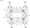
- the insulation structure 1000 of the present disclosure may be applied to each of two ends of a stator S in an axial direction to block an electric field of an end coil assembly C from being applied to a motor shaft, and serve to prevent the electric field from the coil assembly inserted into the stator S from being delivered to a rotor structure R.
- the insulation structure 1000 of the present disclosure may include a conducting part 100 and an insulating part 200.
- the conducting part 100 may extend in an induction direction parallel to a direction in which the end coil assembly C is pulled out from the stator S, and thus induce the electric field of the end coil assembly C to be directed in the induction direction.
- the insulating part 200 may be positioned between the conducting part 100 and the end coil assembly C to insulate the conducting part 100.
- the conducting part 100 may be positioned inside the end coil assembly C (to be close to the rotor structure R), and the insulating part 200 may surround the conducting part 100.
- the insulating part 200 may include an insulating paper having one surface in contact with an inner surface of the end coil assembly C.
- the insulating paper may include a first insulating part 210 bent and surrounding an entire outer surface of the conducting part 100, and a coupling part 220 formed by pulling out and coupling both ends the first insulating part 210 to each other.
- the coupling part 220 may be formed by bond-coupling both the ends of the first insulating part 210 to each other.
- the electric field of the end coil assembly C may be moved along the conducting part 100 by adopting a first embodiment of the insulation structure 1000 of the present disclosure, thus minimizing the electric field delivered to the rotor structure R.
- the insulating part 200 may surround the entire surface of the conducting part 100, and the conducting part 100 and the end coil assembly C may thus be insulated from each other without a current flowing therebetween. Accordingly, compared to a method of inducing the electric field by grounding to the end coil, it is possible to induce the electric field without connecting each end coil strand with the conducting part 100, thereby increasing manufacturing convenience and stability.
- the insulating part 200 may protect the conducting part 100 from an external stimulus such as cooling oil, thus maintaining durability of a motor.
- the coupling part 220 may be disposed at each of two ends of the conducting part 100 in an extension direction, and in contact with each of the two ends of the stator S. Accordingly, the coupling part 220 may not interfere with an electric field delivery path, thus maximizing an axis voltage reduction effect, and prevent the bonding of the coupling part 220 from being damaged by the cooling oil or a motor housing H.
- the following is a comparison of changes in a charge on a surface of the rotor structure R based on whether a first embodiment of the insulation structure 1000 of the present disclosure is applied thereto. As a result, it is confirmed that the charge remains on the surface of the rotor structure R when the insulation structure 1000 is not applied to the end coil assembly C. On the other hand, it may be confirmed that the charge on the surface of the rotor structure R is reduced when a first embodiment of the insulation structure 1000 is applied to the end coil assembly C. It is confirmed also from an experiment that the axis voltage is decreased by about 69% in an experimental group to which a first embodiment of the insulation structure 1000 of the present disclosure is applied, compared to a non-experimental group.
- the insulating part 200 of the insulation structure 1000 of the present disclosure may be formed by depositing insulation coating of the end coil assembly C, and the conducting part 100 may be in contact with the deposited insulation coating of the end coil assembly C.
- the conducting part 100 may extend in the induction direction to be longer than the maximum length of the end coil assembly C pulled out from each of the two ends of the stator S. Accordingly, the insulation structure 1000 of the present disclosure may more reliably shield the electric field of the end coil assembly C from being delivered to the rotor structure R.
- the other surface of the insulating paper may be in contact with the motor housing H by an extension length of the conducting part 100, and one surface or the other surface of the insulating paper may be spaced apart from the motor shaft and the rotor structure R by a predetermined distance. Accordingly, as shown by an arrow in FIG. 2 , the electric field may be moved (or delivered in an order of the end coil assembly C, the insulation structure 1000, and then the motor housing H). Therefore, an electric field movement path may be more clearly secured compared to a basic form of a first embodiment.
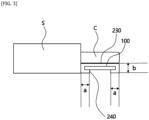
- the insulating paper may include a second insulating part 230 bent and surrounding one surface of the conducting part 100, and a third insulating part 240 formed by pulling out both ends of the second insulating part 230 and bending the same to partially surround the other surface of the conducting part 100.
- a length 'a' of the third insulating part 240 surrounding the other surface of the conducting part 100 may be 2 mm or more, and may be less than 0.5 times the extension length of the conducting part 100.
- a length a+b of the third insulating part 240 extending from the second insulating part 230 may be 2 mm or more.
- an open portion of the conducting part 100 may be bonded to protect the conducting part 100 from an external environment such as the cooling oil.
- the insulating part 200 may be partially open, and the conducting part 100 may thus be easily attached and detached even after the insulating part 200 is bent, thereby increasing convenience in product repair and supplementation.
- the conducting part 100 may include a first conducting part 110 positioned inside the end coil assembly C, a second conducting part 120 positioned on each of the two ends of the stator S and positioned outside the end coil assembly C, and a connecting part 130 connecting the first conducting part 110 with the second conducting part 120.
- the insulating paper may surround the conducting part 100, and be in contact with the inner surface of the end coil assembly C and each of the two ends of the stator S.
- the insulating paper may include a fourth insulating part 250 surrounding an entire outer surface of the first conducting part 110 and in contact with the inner surface of the end coil assembly C, a fifth insulating part 260 surrounding an entire outer surface of the second conducting part 120 and in contact with either end of the stator S, and a sixth insulating part 270 surrounding an entire outer surface of the connecting part 130.
- connecting parts 130 may be provided and spaced apart from each other at equal intervals. It is thus possible to lower a failure rate of the electric field movement path. Only one connecting part 130 may be provided when the failure rate does not need to be considered (that is, when production accuracy is secured). In addition, a width of connecting part 130 may be smaller than 80% of a tooth thickness of the stator S. Accordingly, the insulating part 200 may not interfere with the pulling out of the end coil assembly C.
- the electric field may be moved in an order of the end coil assembly C, the first conducting part 110, the connecting part 130, the second conducting part 120, and then the motor housing H by adopting a third embodiment of the insulation structure 1000 of the present disclosure. That is, the electric field may be induced outside the stator S (that is, opposite to the rotor structure R, and toward the motor housing H). Accordingly, there may be no limitation in designing the motor using the insulation structure 1000 of the present disclosure. That is, it is possible to clearly secure the electric field movement path, and minimize the delivery of the electric field to the rotor structure R even when the two ends of the end coil assembly C and motor housing H of the motor are not adjacent to each other. It is confirmed also from an experiment that the axis voltage is decreased by about 28% in an experimental group to which a third embodiment of the insulation structure 1000 of the present disclosure is applied, compared to a non-experimental group.
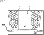
- the insulating paper of the insulating part 200 may have a circular band shape, and its inner diameter may be larger than an inner diameter of a stator core by a predetermined error range, and the error range may be at least 0.4 mm.
- a thickness d1 of the insulating paper may be smaller than a shoe thickness d2 of the stator core of the stator S.
- the thickness of the insulating paper may be 0.3 mm or more for ease of manufacture.
- the insulation structure of the present disclosure including the above configuration may reduce the production cost by adopting the method of reducing the magnitude of the axis voltage itself instead of using the expensive ceramic bearing and proposing the insulation structure that may be directly applied to the end coil to thus minimize the motor failure caused by the corrosion, and simultaneously use the inexpensive steel ball bearing.
Landscapes
- Engineering & Computer Science (AREA)
- Power Engineering (AREA)
- Physics & Mathematics (AREA)
- Electromagnetism (AREA)
- Insulation, Fastening Of Motor, Generator Windings (AREA)
Abstract
Description
- The following disclosure relates to an insulation structure applied to a motor.
- A prior interior permanent magnet (IPM)-type motor has a permanent magnet embedded in a rotor, and may be driven by pulse width modulation (PWM) control of an inverter delivering power to a coil assembly. A common mode voltage may be applied to parasitic capacitance of the motor by the PWM control, thus generating an axis voltage between the shaft axis and bearing of the motor.
- When the axis voltage is generated between the shaft axis of the motor and the bearing, and a bearing ball and an inner/outer ring come into contact with each other in a case where the motor is running, an axis current may flow through the bearing due to the axis voltage, which may cause bearing corrosion. The bearing corrosion may cause a bearing noise and excessive vibration, which may cause motor failure in the long term.
- In addition, as specifications required for the motor are gradually increased, a voltage of the power applied to the motor may be increased, and a carrier frequency used by the inverter may tend to be increased. As a result, the axis voltage and the axis current, which are main causes of the bearing corrosion, may also be increased, resulting in an increase in the frequency of failures caused by the bearing corrosion.
- In order to solve this problem, the prior art may use a ceramic bearing, an SGR bearing, or an RGC bearing. However, in this case, a material cost may be increased. In addition, even though using such an anti-corrosion structure, a motor adopting an oil cooling method may have an oil film formed between its structure and a rotor assembly, and thus have a significantly lower anti-corrosion effect.
- This Summary is provided to introduce a selection of concepts in simplified form that are further described below in the Detailed Description. This Summary is not intended to identify key features or essential features of the claimed subject matter, nor is it intended to be used as an aid in determining the scope of the claimed subject matter.
- An embodiment of the present disclosure is directed to providing an insulation structure which may reduce a production cost by adopting a method of reducing a magnitude of an axis voltage itself instead of using an expensive ceramic bearing and proposing an insulation structure that may be directly applied to an end coil to thus minimize a motor failure caused by corrosion, and simultaneously use an inexpensive steel ball bearing.
- In one general aspect, an insulation structure applied to each of two ends of a stator in an axial direction to block an electric field of an end coil assembly from being applied to a motor shaft includes: a conducting part extending in a predetermined induction direction parallel to a direction in which the end coil assembly is pulled out from the stator and inducing the electric field of the end coil assembly to be directed in the induction direction; and an insulating part positioned between the conducting part and the end coil assembly to insulate the conducting part.
- The conducting part may be positioned inside the end coil assembly, and the insulating part may surround the conducting part, and include an insulating paper having a first surface in contact with an inner surface of the end coil assembly.
- The insulating paper may include a first insulating part bent and surrounding an entire outer surface of the conducting part, and a coupling part formed by pulling out and coupling both ends of the first insulating part to each other.
- The conducting part may extend in the induction direction to be longer than a maximum length of the end coil assembly pulled out from each of the two ends of the stator.
- A second surface of the insulating paper may be in contact with the motor housing, and one of the first and second surfaces of the insulating paper may be spaced apart from the motor shaft and a rotor structure by a predetermined distance.
- The insulating paper may include a second insulating part bent and surrounding a first surface of the conducting part, and a third insulating part formed by pulling out both ends of the second insulating part and bending the ends to partially surround a second surface of the conducting part.
- The conducting part may include a first conducting part positioned inside the end coil assembly, a second conducting part positioned on each of the two ends of the stator and positioned outside the end coil assembly, and a connecting part having two ends to which the first conducting part and the second conducting part are respectively connected, and the insulating paper surrounds the conducting part, and is in contact with the inner surface of the end coil assembly and each of the two ends of the stator.
- The insulating paper may include a fourth insulating part surrounding an entire outer surface of the first conducting part and in contact with the inner surface of the end coil assembly, a fifth insulating part surrounding an entire outer surface of the second conducting part and in contact with either end of the stator, and a sixth insulating part surrounding an entire outer surface of the connecting part.
- A thickness of the insulating paper may be smaller than a shoe thickness of a stator core of the stator.
- Other features and aspects will be apparent from the following detailed description, the drawings, and the claims.
-
-
FIG. 1 is a cross-sectional view showing an internal structure of a motor using a first embodiment of an insulation structure of the present disclosure. -
FIG. 2 is a schematic view showing an application form of a first embodiment of the insulation structure of the present disclosure. -
FIG. 3 is a schematic view showing a second embodiment of the insulation structure of the present disclosure. -
FIG. 4 is a schematic view showing a third embodiment of the insulation structure of the present disclosure. -
FIG. 5 is a perspective view showing a third embodiment of the insulation structure of the present disclosure. -
FIG. 6 is a perspective view of a stator using a third embodiment of the insulation structure of the present disclosure. -
FIG. 7 is a partial plan view of a stator using the insulation structure of the present disclosure. - Hereinafter, the spirit of the present disclosure is described in more detail with reference to the accompanying drawings. Terms and words used in the specification and claims are not to be construed as general or dictionary meanings, and are to be construed as meanings and concepts meeting the spirit of the present disclosure based on a principle in which the inventors may appropriately define the concepts of terms in order to describe their inventions in the best mode.
- Hereinafter, the description describes a basic configuration of an
insulation structure 1000 and a first embodiment of the present disclosure with reference toFIG. 1 . - The
insulation structure 1000 of the present disclosure may be applied to each of two ends of a stator S in an axial direction to block an electric field of an end coil assembly C from being applied to a motor shaft, and serve to prevent the electric field from the coil assembly inserted into the stator S from being delivered to a rotor structure R. In detail, theinsulation structure 1000 of the present disclosure may include a conductingpart 100 and aninsulating part 200. The conductingpart 100 may extend in an induction direction parallel to a direction in which the end coil assembly C is pulled out from the stator S, and thus induce the electric field of the end coil assembly C to be directed in the induction direction. In addition, theinsulating part 200 may be positioned between the conductingpart 100 and the end coil assembly C to insulate the conductingpart 100. - In detail, as shown in a first embodiment shown in
FIG. 1 , in the present disclosure of theinsulation structure 1000, the conductingpart 100 may be positioned inside the end coil assembly C (to be close to the rotor structure R), and theinsulating part 200 may surround the conductingpart 100. Here, theinsulating part 200 may include an insulating paper having one surface in contact with an inner surface of the end coil assembly C. Here, the insulating paper may include a first insulatingpart 210 bent and surrounding an entire outer surface of the conductingpart 100, and acoupling part 220 formed by pulling out and coupling both ends the first insulatingpart 210 to each other. Thecoupling part 220 may be formed by bond-coupling both the ends of the first insulatingpart 210 to each other. - The electric field of the end coil assembly C may be moved along the conducting
part 100 by adopting a first embodiment of theinsulation structure 1000 of the present disclosure, thus minimizing the electric field delivered to the rotor structure R. In addition, theinsulating part 200 may surround the entire surface of the conductingpart 100, and the conductingpart 100 and the end coil assembly C may thus be insulated from each other without a current flowing therebetween. Accordingly, compared to a method of inducing the electric field by grounding to the end coil, it is possible to induce the electric field without connecting each end coil strand with the conductingpart 100, thereby increasing manufacturing convenience and stability. In addition, theinsulating part 200 may protect the conductingpart 100 from an external stimulus such as cooling oil, thus maintaining durability of a motor. - Further, the
coupling part 220 may be disposed at each of two ends of the conductingpart 100 in an extension direction, and in contact with each of the two ends of the stator S. Accordingly, thecoupling part 220 may not interfere with an electric field delivery path, thus maximizing an axis voltage reduction effect, and prevent the bonding of thecoupling part 220 from being damaged by the cooling oil or a motor housing H. - The following is a comparison of changes in a charge on a surface of the rotor structure R based on whether a first embodiment of the
insulation structure 1000 of the present disclosure is applied thereto. As a result, it is confirmed that the charge remains on the surface of the rotor structure R when theinsulation structure 1000 is not applied to the end coil assembly C. On the other hand, it may be confirmed that the charge on the surface of the rotor structure R is reduced when a first embodiment of theinsulation structure 1000 is applied to the end coil assembly C. It is confirmed also from an experiment that the axis voltage is decreased by about 69% in an experimental group to which a first embodiment of theinsulation structure 1000 of the present disclosure is applied, compared to a non-experimental group. - In addition, the
insulating part 200 of theinsulation structure 1000 of the present disclosure may be formed by depositing insulation coating of the end coil assembly C, and the conductingpart 100 may be in contact with the deposited insulation coating of the end coil assembly C. - Hereinafter, the description describes an application form of a first embodiment of the
insulation structure 1000 of the present disclosure in more detail with reference toFIG. 2 . - In a first-1-th embodiment of the
insulation structure 1000 of the present disclosure shown inFIG. 2 , the conductingpart 100 may extend in the induction direction to be longer than the maximum length of the end coil assembly C pulled out from each of the two ends of the stator S. Accordingly, theinsulation structure 1000 of the present disclosure may more reliably shield the electric field of the end coil assembly C from being delivered to the rotor structure R. - Further, in a first-2-th embodiment of the
insulation structure 1000 of the present disclosure shown inFIG. 2 , the other surface of the insulating paper may be in contact with the motor housing H by an extension length of the conductingpart 100, and one surface or the other surface of the insulating paper may be spaced apart from the motor shaft and the rotor structure R by a predetermined distance. Accordingly, as shown by an arrow inFIG. 2 , the electric field may be moved (or delivered in an order of the end coil assembly C, theinsulation structure 1000, and then the motor housing H). Therefore, an electric field movement path may be more clearly secured compared to a basic form of a first embodiment. - Hereinafter, the description describes a second embodiment of the
insulation structure 1000 of the present disclosure in more detail with reference toFIG. 3 . - In a second embodiment of the
insulation structure 1000 of the present disclosure shown inFIG. 3 , the insulating paper may include a second insulatingpart 230 bent and surrounding one surface of the conductingpart 100, and a third insulatingpart 240 formed by pulling out both ends of the second insulatingpart 230 and bending the same to partially surround the other surface of the conductingpart 100. Here, a length 'a' of the third insulatingpart 240 surrounding the other surface of the conductingpart 100 may be 2 mm or more, and may be less than 0.5 times the extension length of the conductingpart 100. In addition, a length a+b of the third insulatingpart 240 extending from the secondinsulating part 230 may be 2 mm or more. In addition, an open portion of the conductingpart 100 may be bonded to protect the conductingpart 100 from an external environment such as the cooling oil. - It is thus possible to lower a cost of materials used for the
insulating part 200 by adopting a second embodiment of theinsulation structure 1000 of the present disclosure. In addition, theinsulating part 200 may be partially open, and the conductingpart 100 may thus be easily attached and detached even after the insulatingpart 200 is bent, thereby increasing convenience in product repair and supplementation. - Hereinafter, the description describes a third embodiment of the
insulation structure 1000 of the present disclosure in more detail with reference toFIGS. 4 to 6 . - In a third embodiment of the
insulation structure 1000 of the present disclosure shown inFIG. 4 , the conductingpart 100 may include a first conductingpart 110 positioned inside the end coil assembly C, a second conductingpart 120 positioned on each of the two ends of the stator S and positioned outside the end coil assembly C, and a connectingpart 130 connecting the first conductingpart 110 with the second conductingpart 120. Here, the insulating paper may surround the conductingpart 100, and be in contact with the inner surface of the end coil assembly C and each of the two ends of the stator S. - In detail, as shown in
FIG. 5 , the insulating paper may include a fourth insulatingpart 250 surrounding an entire outer surface of the first conductingpart 110 and in contact with the inner surface of the end coil assembly C, a fifth insulatingpart 260 surrounding an entire outer surface of thesecond conducting part 120 and in contact with either end of the stator S, and a sixth insulatingpart 270 surrounding an entire outer surface of the connectingpart 130. - Here, two or more connecting
parts 130 may be provided and spaced apart from each other at equal intervals. It is thus possible to lower a failure rate of the electric field movement path. Only one connectingpart 130 may be provided when the failure rate does not need to be considered (that is, when production accuracy is secured). In addition, a width of connectingpart 130 may be smaller than 80% of a tooth thickness of the stator S. Accordingly, the insulatingpart 200 may not interfere with the pulling out of the end coil assembly C. - As shown by an arrow in
FIG. 6 , the electric field may be moved in an order of the end coil assembly C, the first conductingpart 110, the connectingpart 130, thesecond conducting part 120, and then the motor housing H by adopting a third embodiment of theinsulation structure 1000 of the present disclosure. That is, the electric field may be induced outside the stator S (that is, opposite to the rotor structure R, and toward the motor housing H). Accordingly, there may be no limitation in designing the motor using theinsulation structure 1000 of the present disclosure. That is, it is possible to clearly secure the electric field movement path, and minimize the delivery of the electric field to the rotor structure R even when the two ends of the end coil assembly C and motor housing H of the motor are not adjacent to each other. It is confirmed also from an experiment that the axis voltage is decreased by about 28% in an experimental group to which a third embodiment of theinsulation structure 1000 of the present disclosure is applied, compared to a non-experimental group. - Hereinafter, the description describes a fourth embodiment of the
insulation structure 1000 of the present disclosure in more detail with reference toFIG. 7 . - As described above, the insulating paper of the insulating
part 200 may have a circular band shape, and its inner diameter may be larger than an inner diameter of a stator core by a predetermined error range, and the error range may be at least 0.4 mm. In addition, as shown in FIG. 9, a thickness d1 of the insulating paper may be smaller than a shoe thickness d2 of the stator core of the stator S. In addition, the thickness of the insulating paper may be 0.3 mm or more for ease of manufacture. - As set forth above, the insulation structure of the present disclosure including the above configuration may reduce the production cost by adopting the method of reducing the magnitude of the axis voltage itself instead of using the expensive ceramic bearing and proposing the insulation structure that may be directly applied to the end coil to thus minimize the motor failure caused by the corrosion, and simultaneously use the inexpensive steel ball bearing.
- The spirit of the present disclosure should not be limited to the embodiments described above. The present disclosure may be applied to various fields, and may be variously modified by those skilled in the art without departing from the scope of the present disclosure claimed in the claims. Therefore, it is obvious to those skilled in the art that these alterations and modifications fall within the scope of the present disclosure.
Claims (9)
- An insulation structure applied to each of two ends of a stator in an axial direction to block an electric field of an end coil assembly from being applied to a motor shaft, the structure comprising:a conducting part extending in a predetermined induction direction parallel to a direction in which the end coil assembly is pulled out from the stator; andan insulating part positioned between the conducting part and the end coil assembly to insulate the conducting part.
- The insulation structure of claim 1, wherein the conducting part is positioned inside the end coil assembly, and
the insulating part surrounds the conducting part, and includes an insulating paper having a first surface in contact with an inner surface of the end coil assembly. - The insulation structure of claim 2, wherein the insulating paper includes:a first insulating part bent and surrounding an entire outer surface of the conducting part; anda coupling part formed by pulling out and coupling both ends of the first insulating part to each other.
- The insulation structure of any one of claims 1 to 3, wherein the conducting part extends in the induction direction to be longer than a maximum length of the end coil assembly pulled out from each of the two ends of the stator.
- The insulation structure of any one of claims 2 to 4, wherein a second surface of the insulating paper is in contact with the motor housing, and
one of the first and second surfaces of the insulating paper is spaced apart from the motor shaft and a rotor structure by a predetermined distance. - The insulation structure of any one of claims 2 to 5, wherein the insulating paper includes:a second insulating part bent and surrounding a first surface of the conducting part; anda third insulating part formed by pulling out both ends of the second insulating part and bending the ends to partially surround a second surface of the conducting part.
- The insulation structure of any one of claims 2 to 6, wherein the conducting part includes:a first conducting part positioned inside the end coil assembly;a second conducting part positioned on each of the two ends of the stator and positioned outside the end coil assembly; anda connecting part having two ends to which the first conducting part and the second conducting part are respectively connected, whereinthe insulating paper surrounds the conducting part, and is in contact with the inner surface of the end coil assembly and each of the two ends of the stator.
- The insulation structure of claim 7, wherein the insulating paper includes:a fourth insulating part surrounding an entire outer surface of the first conducting part and in contact with the inner surface of the end coil assembly;a fifth insulating part surrounding an entire outer surface of the second conducting part and in contact with either end of the stator; anda sixth insulating part surrounding an entire outer surface of the connecting part.
- The insulation structure of any one of claims 2 to 8, wherein a thickness of the insulating paper is smaller than a shoe thickness of a stator core of the stator.
Applications Claiming Priority (1)
| Application Number | Priority Date | Filing Date | Title |
|---|---|---|---|
| KR1020230037202A KR102781729B1 (en) | 2023-03-22 | 2023-03-22 | insulation structure |
Publications (2)
| Publication Number | Publication Date |
|---|---|
| EP4436014A1 true EP4436014A1 (en) | 2024-09-25 |
| EP4436014B1 EP4436014B1 (en) | 2026-04-01 |
Family
ID=89619117
Family Applications (1)
| Application Number | Title | Priority Date | Filing Date |
|---|---|---|---|
| EP24151526.1A Active EP4436014B1 (en) | 2023-03-22 | 2024-01-12 | Insulation structure |
Country Status (4)
| Country | Link |
|---|---|
| US (1) | US12614944B2 (en) |
| EP (1) | EP4436014B1 (en) |
| KR (1) | KR102781729B1 (en) |
| CN (1) | CN118694052A (en) |
Citations (7)
| Publication number | Priority date | Publication date | Assignee | Title |
|---|---|---|---|---|
| US5979087A (en) * | 1998-01-16 | 1999-11-09 | Reliance Electric Industrial Company | Electric motor having electrostatic shield arrangement |
| US7113365B1 (en) * | 2002-12-24 | 2006-09-26 | Western Digital Technologies, Inc. | Disk drive comprising a spindle motor having a windings shield for reduced disk voltage coupling |
| US20080238230A1 (en) * | 2007-03-27 | 2008-10-02 | Sony Corporation | Motor |
| WO2016091360A2 (en) * | 2014-12-10 | 2016-06-16 | Audi Ag | Electric machine and motor vehicle |
| EP3185405A1 (en) * | 2015-12-23 | 2017-06-28 | Grundfos Holding A/S | Electric motor |
| WO2022024365A1 (en) * | 2020-07-31 | 2022-02-03 | 三菱電機株式会社 | Rotating electrical machine |
| US20220255394A1 (en) * | 2021-02-11 | 2022-08-11 | Ebm-Papst Mulfingen Gmbh & Co. Kg | Electrical machine with grounded shield arrangement |
Family Cites Families (5)
| Publication number | Priority date | Publication date | Assignee | Title |
|---|---|---|---|---|
| JP4665566B2 (en) * | 2005-03-15 | 2011-04-06 | パナソニック株式会社 | Rotating electric machine |
| JP5564341B2 (en) * | 2010-06-21 | 2014-07-30 | 株式会社日立産機システム | Rotating electric machine |
| JP6457422B2 (en) * | 2016-04-07 | 2019-01-23 | ファナック株式会社 | Motor having interphase insulating paper at coil end and manufacturing method thereof |
| KR20220136837A (en) | 2021-04-01 | 2022-10-11 | 박찬희 | Axial current discharge system of Motor and Generator using assistance bearing of electric currentness |
| DE102021113691A1 (en) * | 2021-05-27 | 2022-12-01 | Dr. Ing. H.C. F. Porsche Aktiengesellschaft | Stator of an electric drive machine and method of manufacturing the same |
-
2023
- 2023-03-22 KR KR1020230037202A patent/KR102781729B1/en active Active
- 2023-10-25 US US18/494,338 patent/US12614944B2/en active Active
-
2024
- 2024-01-12 EP EP24151526.1A patent/EP4436014B1/en active Active
- 2024-02-29 CN CN202410230867.XA patent/CN118694052A/en active Pending
Patent Citations (7)
| Publication number | Priority date | Publication date | Assignee | Title |
|---|---|---|---|---|
| US5979087A (en) * | 1998-01-16 | 1999-11-09 | Reliance Electric Industrial Company | Electric motor having electrostatic shield arrangement |
| US7113365B1 (en) * | 2002-12-24 | 2006-09-26 | Western Digital Technologies, Inc. | Disk drive comprising a spindle motor having a windings shield for reduced disk voltage coupling |
| US20080238230A1 (en) * | 2007-03-27 | 2008-10-02 | Sony Corporation | Motor |
| WO2016091360A2 (en) * | 2014-12-10 | 2016-06-16 | Audi Ag | Electric machine and motor vehicle |
| EP3185405A1 (en) * | 2015-12-23 | 2017-06-28 | Grundfos Holding A/S | Electric motor |
| WO2022024365A1 (en) * | 2020-07-31 | 2022-02-03 | 三菱電機株式会社 | Rotating electrical machine |
| US20220255394A1 (en) * | 2021-02-11 | 2022-08-11 | Ebm-Papst Mulfingen Gmbh & Co. Kg | Electrical machine with grounded shield arrangement |
Also Published As
| Publication number | Publication date |
|---|---|
| KR20240142760A (en) | 2024-10-02 |
| EP4436014B1 (en) | 2026-04-01 |
| US20240322631A1 (en) | 2024-09-26 |
| KR102781729B1 (en) | 2025-03-17 |
| US12614944B2 (en) | 2026-04-28 |
| CN118694052A (en) | 2024-09-24 |
Similar Documents
| Publication | Publication Date | Title |
|---|---|---|
| US11444502B2 (en) | Coil bobbin, stator core of distributed winding radial gap-type rotating electric machine, and distributed winding radial gap-type rotating electric machine | |
| US8461734B2 (en) | Electric motor having a circuit apparatus | |
| CN103688445B (en) | The stator of motor and permanent magnet type electric rotary machine | |
| JP6373854B2 (en) | Stator or rotor | |
| US20200350804A1 (en) | Electric motor and turbo-compressor | |
| EP3148057B1 (en) | Electric motor | |
| WO2018037449A1 (en) | Consequent-pole-type rotor, electric motor, and air conditioner | |
| WO2021205708A1 (en) | Stator of rotating electrical machine | |
| EP3148056A1 (en) | Electric motor | |
| CN106849526A (en) | Rotor, the motor comprising this rotor and the method for manufacturing rotor | |
| WO2012105193A1 (en) | Molded motor | |
| CN116114151A (en) | rotating electrical machine | |
| WO2021095733A1 (en) | Method for manufacturing dynamo-electric machine | |
| US20230179032A1 (en) | Motor | |
| JP6373494B2 (en) | Rotating electric machine | |
| US12614944B2 (en) | Insulation structure | |
| JP7437502B2 (en) | Compressor drive device and method for manufacturing the device | |
| WO2022168464A1 (en) | Dyanamo-electric machine | |
| JP2020124057A (en) | Rotary electric machine insulator | |
| JP3839800B2 (en) | Ignition circuit unit integrated ignition coil | |
| CN219643674U (en) | Rotor core, rotor, motor and vehicle | |
| KR102869031B1 (en) | Stator of electric motor | |
| WO2021095736A1 (en) | Rotating electric machine | |
| US20240146140A1 (en) | Stator | |
| US8368279B2 (en) | Commutator for an electrical machine, and electrical machine |
Legal Events
| Date | Code | Title | Description |
|---|---|---|---|
| PUAI | Public reference made under article 153(3) epc to a published international application that has entered the european phase |
Free format text: ORIGINAL CODE: 0009012 |
|
| STAA | Information on the status of an ep patent application or granted ep patent |
Free format text: STATUS: THE APPLICATION HAS BEEN PUBLISHED |
|
| AK | Designated contracting states |
Kind code of ref document: A1 Designated state(s): AL AT BE BG CH CY CZ DE DK EE ES FI FR GB GR HR HU IE IS IT LI LT LU LV MC ME MK MT NL NO PL PT RO RS SE SI SK SM TR |
|
| STAA | Information on the status of an ep patent application or granted ep patent |
Free format text: STATUS: REQUEST FOR EXAMINATION WAS MADE |
|
| 17P | Request for examination filed |
Effective date: 20250321 |
|
| STAA | Information on the status of an ep patent application or granted ep patent |
Free format text: STATUS: EXAMINATION IS IN PROGRESS |
|
| 17Q | First examination report despatched |
Effective date: 20250606 |
|
| GRAP | Despatch of communication of intention to grant a patent |
Free format text: ORIGINAL CODE: EPIDOSNIGR1 |
|
| STAA | Information on the status of an ep patent application or granted ep patent |
Free format text: STATUS: GRANT OF PATENT IS INTENDED |
|
| RIC1 | Information provided on ipc code assigned before grant |
Ipc: H02K 11/01 20160101AFI20251017BHEP Ipc: H02K 3/38 20060101ALI20251017BHEP Ipc: H02K 3/42 20060101ALI20251017BHEP Ipc: H01F 5/00 20060101ALI20251017BHEP Ipc: H02K 5/16 20060101ALN20251017BHEP Ipc: H02K 3/30 20060101ALN20251017BHEP Ipc: H01F 27/36 20060101ALN20251017BHEP |
|
| INTG | Intention to grant announced |
Effective date: 20251103 |
|
| GRAS | Grant fee paid |
Free format text: ORIGINAL CODE: EPIDOSNIGR3 |
|
| GRAA | (expected) grant |
Free format text: ORIGINAL CODE: 0009210 |
|
| STAA | Information on the status of an ep patent application or granted ep patent |
Free format text: STATUS: THE PATENT HAS BEEN GRANTED |
|
| P01 | Opt-out of the competence of the unified patent court (upc) registered |
Free format text: CASE NUMBER: UPC_APP_0004243_4436014/2026 Effective date: 20260205 |
|
| AK | Designated contracting states |
Kind code of ref document: B1 Designated state(s): AL AT BE BG CH CY CZ DE DK EE ES FI FR GB GR HR HU IE IS IT LI LT LU LV MC ME MK MT NL NO PL PT RO RS SE SI SK SM TR |
|
| REG | Reference to a national code |
Ref country code: CH Ref legal event code: F10 Free format text: ST27 STATUS EVENT CODE: U-0-0-F10-F00 (AS PROVIDED BY THE NATIONAL OFFICE) Effective date: 20260401 Ref country code: GB Ref legal event code: FG4D |
|
| REG | Reference to a national code |
Ref country code: IE Ref legal event code: FG4D |
|
| REG | Reference to a national code |
Ref country code: DE Ref legal event code: R096 Ref document number: 602024003484 Country of ref document: DE |
|
| REG | Reference to a national code |
Ref country code: NL Ref legal event code: MP Effective date: 20260401 |