EP4435915A2 - Electrode assembly, electrochemical apparatus and electrical device - Google Patents
Electrode assembly, electrochemical apparatus and electrical device Download PDFInfo
- Publication number
- EP4435915A2 EP4435915A2 EP24164467.3A EP24164467A EP4435915A2 EP 4435915 A2 EP4435915 A2 EP 4435915A2 EP 24164467 A EP24164467 A EP 24164467A EP 4435915 A2 EP4435915 A2 EP 4435915A2
- Authority
- EP
- European Patent Office
- Prior art keywords
- section
- dissociative
- electrode
- electrode plate
- wall
- Prior art date
- Legal status (The legal status is an assumption and is not a legal conclusion. Google has not performed a legal analysis and makes no representation as to the accuracy of the status listed.)
- Pending
Links
- 239000013543 active substance Substances 0.000 claims abstract description 93
- 239000011888 foil Substances 0.000 claims abstract description 59
- 230000007423 decrease Effects 0.000 claims description 8
- 239000000853 adhesive Substances 0.000 description 25
- 230000001070 adhesive effect Effects 0.000 description 25
- 229910052751 metal Inorganic materials 0.000 description 22
- 239000002184 metal Substances 0.000 description 22
- 238000005520 cutting process Methods 0.000 description 20
- 238000003466 welding Methods 0.000 description 11
- 238000000034 method Methods 0.000 description 9
- 238000010586 diagram Methods 0.000 description 8
- 238000000926 separation method Methods 0.000 description 7
- 238000004804 winding Methods 0.000 description 7
- 238000004080 punching Methods 0.000 description 6
- PXHVJJICTQNCMI-UHFFFAOYSA-N Nickel Chemical compound [Ni] PXHVJJICTQNCMI-UHFFFAOYSA-N 0.000 description 4
- 230000009286 beneficial effect Effects 0.000 description 4
- 238000005336 cracking Methods 0.000 description 4
- 239000011267 electrode slurry Substances 0.000 description 4
- 239000000463 material Substances 0.000 description 4
- BASFCYQUMIYNBI-UHFFFAOYSA-N platinum Chemical compound [Pt] BASFCYQUMIYNBI-UHFFFAOYSA-N 0.000 description 4
- 230000007704 transition Effects 0.000 description 4
- RYGMFSIKBFXOCR-UHFFFAOYSA-N Copper Chemical compound [Cu] RYGMFSIKBFXOCR-UHFFFAOYSA-N 0.000 description 2
- RTAQQCXQSZGOHL-UHFFFAOYSA-N Titanium Chemical compound [Ti] RTAQQCXQSZGOHL-UHFFFAOYSA-N 0.000 description 2
- 229910052782 aluminium Inorganic materials 0.000 description 2
- XAGFODPZIPBFFR-UHFFFAOYSA-N aluminium Chemical compound [Al] XAGFODPZIPBFFR-UHFFFAOYSA-N 0.000 description 2
- 230000015572 biosynthetic process Effects 0.000 description 2
- 238000000576 coating method Methods 0.000 description 2
- 229910052802 copper Inorganic materials 0.000 description 2
- 239000010949 copper Substances 0.000 description 2
- 230000000694 effects Effects 0.000 description 2
- 238000005516 engineering process Methods 0.000 description 2
- 238000004519 manufacturing process Methods 0.000 description 2
- 239000000155 melt Substances 0.000 description 2
- 229910052759 nickel Inorganic materials 0.000 description 2
- 229910052697 platinum Inorganic materials 0.000 description 2
- -1 polyethylene Polymers 0.000 description 2
- 230000000717 retained effect Effects 0.000 description 2
- 229910052715 tantalum Inorganic materials 0.000 description 2
- GUVRBAGPIYLISA-UHFFFAOYSA-N tantalum atom Chemical compound [Ta] GUVRBAGPIYLISA-UHFFFAOYSA-N 0.000 description 2
- 229910052719 titanium Inorganic materials 0.000 description 2
- 239000010936 titanium Substances 0.000 description 2
- 229910052727 yttrium Inorganic materials 0.000 description 2
- 239000004698 Polyethylene Substances 0.000 description 1
- 239000004743 Polypropylene Substances 0.000 description 1
- 238000004140 cleaning Methods 0.000 description 1
- 238000004146 energy storage Methods 0.000 description 1
- 230000014509 gene expression Effects 0.000 description 1
- 239000011521 glass Substances 0.000 description 1
- 238000002844 melting Methods 0.000 description 1
- 230000008018 melting Effects 0.000 description 1
- 238000012986 modification Methods 0.000 description 1
- 230000004048 modification Effects 0.000 description 1
- 239000002985 plastic film Substances 0.000 description 1
- 229920006255 plastic film Polymers 0.000 description 1
- 229920006267 polyester film Polymers 0.000 description 1
- 229920000573 polyethylene Polymers 0.000 description 1
- 229920001721 polyimide Polymers 0.000 description 1
- 229920001155 polypropylene Polymers 0.000 description 1
Images



Classifications
-
- H—ELECTRICITY
- H01—ELECTRIC ELEMENTS
- H01M—PROCESSES OR MEANS, e.g. BATTERIES, FOR THE DIRECT CONVERSION OF CHEMICAL ENERGY INTO ELECTRICAL ENERGY
- H01M4/00—Electrodes
- H01M4/02—Electrodes composed of, or comprising, active material
- H01M4/64—Carriers or collectors
- H01M4/70—Carriers or collectors characterised by shape or form
-
- H—ELECTRICITY
- H01—ELECTRIC ELEMENTS
- H01M—PROCESSES OR MEANS, e.g. BATTERIES, FOR THE DIRECT CONVERSION OF CHEMICAL ENERGY INTO ELECTRICAL ENERGY
- H01M10/00—Secondary cells; Manufacture thereof
- H01M10/04—Construction or manufacture in general
- H01M10/0431—Cells with wound or folded electrodes
-
- H—ELECTRICITY
- H01—ELECTRIC ELEMENTS
- H01M—PROCESSES OR MEANS, e.g. BATTERIES, FOR THE DIRECT CONVERSION OF CHEMICAL ENERGY INTO ELECTRICAL ENERGY
- H01M10/00—Secondary cells; Manufacture thereof
- H01M10/05—Accumulators with non-aqueous electrolyte
- H01M10/058—Construction or manufacture
- H01M10/0587—Construction or manufacture of accumulators having only wound construction elements, i.e. wound positive electrodes, wound negative electrodes and wound separators
-
- H—ELECTRICITY
- H01—ELECTRIC ELEMENTS
- H01M—PROCESSES OR MEANS, e.g. BATTERIES, FOR THE DIRECT CONVERSION OF CHEMICAL ENERGY INTO ELECTRICAL ENERGY
- H01M50/00—Constructional details or processes of manufacture of the non-active parts of electrochemical cells other than fuel cells, e.g. hybrid cells
- H01M50/50—Current conducting connections for cells or batteries
- H01M50/531—Electrode connections inside a battery casing
-
- H—ELECTRICITY
- H01—ELECTRIC ELEMENTS
- H01M—PROCESSES OR MEANS, e.g. BATTERIES, FOR THE DIRECT CONVERSION OF CHEMICAL ENERGY INTO ELECTRICAL ENERGY
- H01M50/00—Constructional details or processes of manufacture of the non-active parts of electrochemical cells other than fuel cells, e.g. hybrid cells
- H01M50/50—Current conducting connections for cells or batteries
- H01M50/531—Electrode connections inside a battery casing
- H01M50/533—Electrode connections inside a battery casing characterised by the shape of the leads or tabs
-
- Y—GENERAL TAGGING OF NEW TECHNOLOGICAL DEVELOPMENTS; GENERAL TAGGING OF CROSS-SECTIONAL TECHNOLOGIES SPANNING OVER SEVERAL SECTIONS OF THE IPC; TECHNICAL SUBJECTS COVERED BY FORMER USPC CROSS-REFERENCE ART COLLECTIONS [XRACs] AND DIGESTS
- Y02—TECHNOLOGIES OR APPLICATIONS FOR MITIGATION OR ADAPTATION AGAINST CLIMATE CHANGE
- Y02E—REDUCTION OF GREENHOUSE GAS [GHG] EMISSIONS, RELATED TO ENERGY GENERATION, TRANSMISSION OR DISTRIBUTION
- Y02E60/00—Enabling technologies; Technologies with a potential or indirect contribution to GHG emissions mitigation
- Y02E60/10—Energy storage using batteries
-
- Y—GENERAL TAGGING OF NEW TECHNOLOGICAL DEVELOPMENTS; GENERAL TAGGING OF CROSS-SECTIONAL TECHNOLOGIES SPANNING OVER SEVERAL SECTIONS OF THE IPC; TECHNICAL SUBJECTS COVERED BY FORMER USPC CROSS-REFERENCE ART COLLECTIONS [XRACs] AND DIGESTS
- Y02—TECHNOLOGIES OR APPLICATIONS FOR MITIGATION OR ADAPTATION AGAINST CLIMATE CHANGE
- Y02P—CLIMATE CHANGE MITIGATION TECHNOLOGIES IN THE PRODUCTION OR PROCESSING OF GOODS
- Y02P70/00—Climate change mitigation technologies in the production process for final industrial or consumer products
- Y02P70/50—Manufacturing or production processes characterised by the final manufactured product
Definitions
- This application relates to the technical field of energy storage, in particular to an electrode assembly, an electrochemical apparatus and an electrical device.
- the electrode assembly of the wound cell includes an electrode plate and an electrode tab connected to the electrode plate.
- the method for the connection between the electrode tab and the electrode plate is usually to remove the active substance layer on the electrode plate to obtain an empty foil area in which the current collector is exposed, and to weld the electrode tab to the empty foil area. Since the electrode tab itself occupies a certain thickness, in a case that the active substance layer on the electrode plate is thin, the electrode tab may go beyond the electrode plate in the thickness direction, resulting in low space utilization rate of the electrode assembly in the thickness direction.
- Some embodiments of this application provide an electrode assembly, including a first electrode tab, a first electrode plate, a second electrode plate and a separator, the separator being located between the first electrode plate and the second electrode plate, the first electrode plate, the separator and the second electrode plate being stacked and wound, the first electrode plate including a first current collector and a first active substance layer, the first current collector including a first section, a second section and a third section, a surface of the first section being at least partially provided with the first active substance layer, a surface of the second section being at least partially provided with the first active substance layer; along a first direction, the third section being located between the first section and the second section; along a second direction, the third section including a first dissociative portion and a first connection portion connected sequentially, the first connection portion connecting the first section and the second section; along the first direction, one side of the first dissociative portion being dissociated from the first section, the side of the first dissociative portion opposite to the first section being dissociated from the second section; the first
- the first dissociative portion is dissociated from the first section and the second section, which is conducive to making the first dissociative portion move along the third direction relative to the first section and the second section, thus improving the moving distance of the first electrode tab along the third direction relative to the first section and the second section, enabling the first electrode tab to not go beyond the first active substance layer of the first section and the second section in the third direction, and improving the spatial utilization rate of the electrode component in the third direction.
- the first electrode tab is connected to the first dissociative portion and the first dissociative portion is dissociated from the first section and the second section, which is conducive to reducing the deformation of the third section when the first dissociative portion moves along the third direction, thus reducing the risk that the first active substance layer at the boundary of the area without the first active substance layer and the area with the first active substance layer is separated from the first current collector.
- a first gap is provided between the first dissociative portion and the first section, and a second gap is provided between the first dissociative portion and the second section.
- the first dissociative portion is dissociated from the first section through the first gap and the first dissociative portion is dissociated from the second section through the second gap, which is conducive to reducing the cut-off part of the first electrode plate and increasing the retained part of the first electrode plate, thus improving the energy density of the electrode assembly.
- the first gap and the second gap both extend along the second direction.
- the first gap and the second gap both extend along the second direction, which is conducive to making the shape of the first dissociative portion more regular, thus facilitating the connection between the first electrode tab and the first empty foil area of the first dissociative portion.
- an extension direction of the first gap and an extension direction of the second gap are both inclined relative to the second direction; along the second direction, a distance between the first gap and the first electrode tab in the first direction gradually decreases, and a distance between the second gap and the first electrode tab in the first direction gradually decreases.
- the distance between the first gap and the first electrode tab in the first direction gradually decreases, and the distance between the second gap and the first electrode tab in the first direction gradually decreases, which is conducive to reducing the risk that the separation tool such as cutting knife or punching head interferes with the first electrode tab adhesive in the process of forming the first gap and the second gap.
- a projection of the first electrode tab on the first electrode plate has a length of Wi along the second direction, and along the second direction, a length of the first dissociative portion is W 2 , which satisfies W 1 /2 ⁇ W 2 ⁇ 3W 1 /2.
- W 1 and W 2 satisfy W 1 /2 ⁇ W 2 ⁇ 3W 1 /2, which is conducive to making the moving distance of the first dissociative portion along the third direction satisfy the requirement that the first electrode tab moves to a position in the third direction without going beyond the first active substance layer of the first section and the second section, and also to reducing the risk that the third section is separated from the first section and the second section since the length of the first gap and the second gap along the second direction is too large.
- the first dissociative portion has a first wall facing to the first section, the first section has a second wall facing to the first dissociative portion, a third wall is connected between the first wall and the second wall, and along the first direction, the distance between the first wall and the second wall is D 1 , which satisfies W 2 ⁇ D 1 ⁇ W 2 /20.
- a gap is formed between the first dissociative portion and the first section.
- D 1 and W 2 are enabled to satisfy W 2 ⁇ D 1 ⁇ W 2 /20, which is conducive to reducing the risk of cracking at the third wall due to stress concentration at the third wall since D 1 is too small.
- D 1 is not too large, which is conducive to reducing the risk that the part of the first electrode plate originally provided with the first active substance layer is removed, thus improving the energy density of the electrode assembly.
- the first dissociative portion has a first wall facing to the first section, the first section has a second wall facing to the first dissociative portion, a third wall is connected between the first wall and the second wall, and the third wall is a concave arc-shaped wall.
- the third wall is a concave arc-shaped wall, which is conducive to reducing the stress on the third wall, thus reducing the risk of cracking at the third wall.
- the distance between the first wall and the second wall is D 1
- a diameter corresponding to the third wall is T 1 , which satisfies D 1 ⁇ T 1 ⁇ 5D 1 .
- the diameter T 1 corresponding to the third walls satisfies D 1 ⁇ T 1 ⁇ 5D 1 , which can achieve the effect that the third wall is an arc-shaped wall, and is conducive to reducing the risk of stress concentration since the transition between the third wall and the first wall is not mild enough due to the excessive curvature of the third wall, or to reducing the risk of stress concentration since the transition between the third wall and the second wall is not mild enough.
- the first dissociative portion further has a collection layer area with the first active substance layer, and along the second direction, the collection layer area is located between the first connection portion and the first empty foil area.
- the provided collection layer area is conducive to increasing the area of the first active substance layer, thus improving the energy density of the electrode assembly.
- the collection layer area is provided between the first connection portion and the first empty foil area, rather than on the side of the first empty foil area facing to the first section or the side of the first empty foil area facing to the second section, thus reducing the risk that the first active substance layer in the collection layer area interferes with the movement of the first electrode tab in the third direction, and ensuring that the first electrode tab does not go beyond the first active substance layer of the first section and the second section in the third direction.
- the surface of the first section has a first side empty foil area without the first active substance layer, and along the first direction, the first side empty foil area is located on one side of the first empty foil area, and the first side empty foil area is dissociated from the first empty foil area.
- the first side empty foil area is provided, so that the two opposite sides of the part where the first dissociative portion is separated from the first section are not provided with the first active substance layer, thus reducing the risk that the first active substance layer interferes with the separation process, and facilitating the separation between the first dissociative portion and the first section.
- common methods such as cutting, punching and laser may be used to achieve the separation between the first dissociative portion and the first section.
- the first dissociative portion and the first connection portion are not provided with the first active substance layer.
- the first dissociative portion and the first connection portion are not provided with the first active substance layer, so that the first electrode tab can extend out of the first electrode plate along the second direction, thus making the same first electrode tab have two positions from which the polarity of the first electrode plate can be led out.
- this application further provides an electrochemical apparatus capable of improving energy density and reliability.
- Some embodiments of this application provide an electrochemical apparatus, including a housing and the electrode assembly in any one of the embodiments above, at least a portion of the electrode assembly being provided in the housing.
- the first electrode tab of the electrode assembly does not go beyond the first active substance layer of the first section and the second section in the third direction, thus improving the spatial utilization rate of the electrode assembly in the third direction, and improving the energy density of the electrochemical apparatus.
- the first dissociative portion is dissociated from the first section and the second section, which is conducive to reducing the deformation of the third section when the first dissociative portion moves along the third direction, thus reducing the risk that the first active substance layer at the boundary of the area without the first active substance layer and the area with the first active substance layer is separated from the first current collector, and improving the reliability of the electrochemical apparatus.
- this application further provides an electrical device capable of improving the use duration after charging and the service life.
- Some embodiments of this application provide an electrical device, including a device main body and the electrochemical apparatus in any one of the embodiments above, the electrochemical apparatus being mounted to the device main body.
- the energy density and reliability of the electrochemical apparatus are improved, which is conducive to improving the use duration after charging and the service life of the electrical device, and reducing the failure rate of the electrical device.
- an electrode assembly includes a first electrode tab, and a first electrode plate, a second electrode plate and a separator which are wound.
- the first electrode plate includes a first section, a second section and a third section.
- the third section includes a first dissociative portion and a first connection portion connected sequentially,
- one side of the first dissociative portion is dissociated from the first section, the side of the first dissociative portion opposite to the first section is dissociated from the second section, and a first empty foil area on the first dissociative portion is connected with the first electrode tab.
- the first dissociative portion being dissociated from the first section and the second section is conducive to increasing the moving distance of the first electrode tab along the third direction relative to the first section and the second section, so that the first electrode tab does not go beyond the first active substance layer of the first section and the second section in the third direction, thus improving the spatial utilization rate of the electrode assembly in the third direction.
- the first dissociative portion being dissociated from the first section and the second section is conducive to reducing the deformation of the third section when the first dissociative portion moves along the third direction, thus reducing the risk that the first active substance layer at the boundary of the area without the first active substance layer and the area with the first active substance layer is separated from the first current collector.
- perpendicular is used to describe the ideal state between two components. In actual production or use, there may be an approximately perpendicular state between two components. For example, by describing in conjunction with numerical values, “perpendicular” may refer to that an included angle is between two straight lines is 90° ⁇ 10°, “perpendicular” may also refer to that a dihedral angle between two planes is 90° ⁇ 10°, and “perpendicular” may also refer to that an included angle between a straight line and a plane is 90° ⁇ 10°.
- the two components described as “perpendicular” may not be absolute straight lines or planes, but may be roughly straight lines or planes. From a macro perspective, if the overall extension direction is straight lines or planes, the components may be considered as "straight lines” or "planes".
- the electrode assembly includes a first electrode tab, a first electrode plate, a second electrode plate and a separator.
- the separator is located between the first electrode plate and the second electrode plate.
- the first electrode plate, the separator and the second electrode plate are stacked and wound.
- the first electrode plate includes a first current collector and a first active substance layer.
- the first current collector includes a first section, a second section and a third section. A surface of the first section is at least partially provided with the first active substance layer. A surface of the second section is at least partially provided with the first active substance layer.
- the third section is located between the first section and the second section.
- the third section includes a first dissociative portion and a first connection portion connected sequentially.
- the first connection portion connects the first section and the second section. Along the first direction, one side of the first dissociative portion is dissociated from the first section, and the side of the first dissociative portion opposite to the first section is dissociated from the second section.
- the first dissociative portion has a first empty foil area without the first active substance layer.
- One side of the first empty foil area in a third direction is connected to the first electrode tab.
- the third direction is a thickness direction of the first electrode plate. Every two of the third direction, the first direction and the second direction are perpendicular to each other.
- the first dissociative portion is dissociated from the first section and the second section, which is conducive to making the first dissociative portion move along the third direction relative to the first section and the second section, thus improving the moving distance of the first electrode tab along the third direction relative to the first section and the second section, enabling the first electrode tab to not go beyond the first active substance layer of the first section and the second section in the third direction, and improving the spatial utilization rate of the electrode assembly in the third direction.
- the first electrode tab is connected to the first dissociative portion and the first dissociative portion is dissociated from the first section and the second section, which is conducive to reducing the deformation of the third section when the first dissociative portion moves along the third direction, thus reducing the risk that the first active substance layer at the boundary of the area without the active substance layer and the area with the active substance layer is separated.
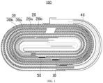
- the electrode assembly 100 includes a first electrode tab 10, a first electrode plate 20, a second electrode plate 30 and a separator 40.
- the separator 40 is located between the first electrode plate 20 and the second electrode plate 30.
- the first electrode plate 20, the separator 40 and the second electrode plate 30 are stacked and wound.
- the first electrode tab 10 is connected to the first electrode plate 20.
- the polarity of the first electrode tab 10 can be positive or negative, and the polarity of the first electrode tab 10 is the same as that of the first electrode plate 20.
- the first electrode tab 10 includes a first metal part 11 and a first electrode tab adhesive 12.
- the first metal part 11 is connected to the first electrode plate 20.
- the material of the first metal part 11 is the same as that of the first electrode plate 20.
- the first electrode tab adhesive 12 is coated on the first metal part 11.
- the first metal part 11 and the first electrode plate 20 are connected by welding.
- the welding method may be resistance welding, laser welding, arc welding or ultrasonic welding.
- the first electrode plate 20 may be a positive electrode plate or a negative electrode plate
- the second electrode plate 30 may be a positive electrode plate or a negative electrode plate
- the polarity of the first electrode plate 20 is opposite to that of the second electrode plate 30.
- the first electrode plate 20 is a positive electrode plate
- the second electrode plate 30 is a negative electrode plate
- the first electrode plate 20 is a negative electrode plate
- the second electrode plate 30 is a positive electrode plate.
- the first electrode plate 20 includes a first current collector 20a and a first active substance layer 20b.
- the first active substance layer 20b is provided on a surface of the first current collector 20a.
- the second electrode plate 30 includes a second current collector 30a and a second active substance layer 30b.
- the second active substance layer 30b is provided on a surface of the second current collector 30a.
- Each of the first current collector 20a and the second current collector 30a includes a metal layer.
- a material of the first active substance layer 20b is different from that of the second active substance layer 30b.
- the positive electrode plate may be combined onto a metal layer of at least one of aluminum, platinum, nickel, tantalum, titanium and the like by using positive electrode slurry.
- the positive electrode slurry combined onto the metal layer forms a positive electrode active substance layer.
- the negative electrode plate may be combined onto a metal layer of at least one of copper, platinum, nickel, tantalum, titanium and the like by using negative electrode slurry.
- the negative electrode slurry combined onto the metal layer forms a negative electrode active substance layer.
- the first electrode plate 20 is a positive electrode plate
- the first current collector 20a includes a metal aluminum layer
- the second electrode plate 30 is a negative electrode plate
- the second current collector 30a includes a metal copper layer.
- the first active substance layer 20b is coated on a surface of the first current collector 20a through a coating process
- the second active substance layer 30b is coated on a surface of the second current collector 30a through a coating process
- the separator 40 is provided between the first electrode plate 20 and the second electrode plate 30 to separate the first electrode plate 20 and the second electrode plate 30 with different polarities.
- the separator 40 is a film material that can insulate, such as a polyethylene film, a polypropylene film, a polyester film or a polyimide film, so as to separate the first electrode plate 20 and the second electrode plate 30.
- the first current collector 20a includes a first section 21, a second section 22, and a third section 23.
- the third section 23 is located between the first section 21 and the second section 22.
- One of the first section 21 and the second section 22 serves as a starting section for the winding of the first electrode plate 20, while the other of the first section 21 and the second section 22 serves as an ending section for the winding of the first electrode plate 20.
- the surfaces of the first section 21 and the second section 22 are at least partially provided with the first active substance layer 20b.
- the third section 23 is connected to the first electrode tab 10.
- the third section 23 is provided with a first empty foil area 2311 without the first active substance layer 20b.
- the first empty foil area 2311 is connected to the first section 21 and the second section 22.
- the first electrode tab 10 is connected to the first empty foil area 2311.
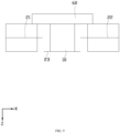
- the first electrode tab 10 goes beyond the first active substance layer 20b of the first section 21 and the second section 22 along the thickness direction of the first electrode plate.
- the first electrode tab 10 is squeezed along the thickness direction of the first electrode plate, causing the first electrode tab 10 to move a certain distance along the thickness direction of the first electrode plate.
- the moving distance of the first electrode tab 10 is limited by the first section 21 and the second section 22, Therefore, the first electrode tab 10 still goes beyond the first active substance layer 20b of the first section 21 and the second section 22 along the thickness direction of the first electrode plate, and the movement of the first electrode tab 10 drives the deformation of the third section 23, which easily causes the first active substance layer 20b at the boundary of the first empty foil area 2311 to separate.
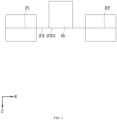
- the third section 23 includes a first dissociative portion 231 and a first connection portion 232 sequentially connected along a second direction Y.
- the first connection portion 232 connects the first section 21 and the second section 22.
- the third direction Z is a thickness direction of the first electrode plate.
- the surface of the first dissociative portion 231 has a first empty foil area 2311 without the first active substance layer 20b.
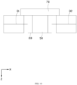
- One side of the first empty foil area 2311 in the third direction Z is connected with the first electrode tab 10, which is conducive to increasing the moving distance of the first electrode tab 10 along the third direction Z relative to the first section 21 and the second section 22.
- the first electrode tab 10 is squeezed along the third direction Z or in a direction opposite to the third direction Z, causing the first electrode tab 10 to move along the third direction Z until the first electrode tab 10 does not go beyond the first active substance layer 20b of the first section 21 and the second section 22 in the third direction Z.
- the first electrode tab 10 not going beyond the first active substance layer 20b of the first section 21 and the second section 22 in the third direction Z is conducive to improving the spatial utilization rate of the electrode assembly 100 in the third direction Z.
- first electrode tab 10 is connected to the first dissociative portion 231 and the first dissociative portion 231 is dissociated from the first section 21 and the second section 22, which is conducive to reducing the deformation of the third section 23 when the first dissociative portion 231 moves along the third direction Z, thus reducing the risk that the first active substance layer 20b at the boundary of the area without the first active substance layer 20b and the area with the first active substance layer 20b is separated from the first current collector 20a.
- a first gap 233 is provided between the first dissociative portion 231 and the first section 21, and a second gap 234 is provided between the first dissociative portion 231 and the second section 22.
- the first dissociative portion 231 is dissociated from the first section 21 through the first gap 233
- the first dissociative portion 231 is dissociated from the second section 22 through the second gap 234, which is conducive to reducing the cut-off part of the first electrode plate 20, increasing the retained part of the first electrode plate 20, and improving the energy density of the electrode assembly 100.
- the first gap 233 and the second gap 234 are formed by using a cutting knife 101 to cut the first electrode plate 20 along the second direction Y and cut off a part of the first electrode plate 20, so that the first gap 233 and the second gap 234 are formed in the first electrode plate 20.
- Cutting the first electrode plate 20 along the second direction Y is conducive to reducing the risk of deformation under stress when the first electrode plate 20 is cut.
- the first gap 233 and the second gap 234 are formed by using the cutting knife 101 to cut the first electrode plate 20 along a direction forming an included angle with the second direction Y and perpendicular to the third direction Z, and cut off a part of the first electrode plate 20, so that the first gap 233 and the second gap 234 are formed in the first electrode plate 20.
- Cutting the first electrode plate 20 in a direction forming an included angle with the second direction Y and perpendicular to the third direction Z is conducive to reducing the risk of deformation under stress when the first electrode plate 20 is cut.
- the first gap 233 and the second gap 234 are formed by using the cutting knife 101 to cut the first electrode plate 20 along the third direction Z, and cut off a part of the first electrode plate 20, so that the first gap 233 and the second gap 234 are formed in the first electrode plate 20.
- the first electrode tab 10 includes a first metal part 11 and a first electrode tab adhesive 12
- the first metal part 11 of the first electrode tab 10 is welded to the first electrode plate 20.
- the first electrode tab adhesive 12 is located on one side of the first electrode plate 20 along a direction opposite to the second direction Y. Cutting the first electrode plate 20 along the third direction Z is conducive to reducing the risk that the cutting knife 101 interferes with the first electrode tab adhesive 12 in the cutting process of the first gap 233 and the second gap 234.
- the cutting knife 101 is placed at a position to be dissociated of the first electrode plate 20, and the first electrode plate 20 is wound to wind the cutting knife 101 into the wound structure.
- the cutting knife 101 is extracted from the wound structure and cuts off a part of the first electrode plate 20, so that the first gap 233 and the second gap 234 are formed in the first electrode plate 20. Cutting the first electrode plate 20 after winding is conducive to reducing the risk that the cut-off part of the first electrode plate 20 punctures the separator 40 in the winding process.
- the first gap 233 and the second gap 234 are formed by using a laser emission tool to emit laser towards the first electrode plate 20 along the second direction Y, or in a direction forming an included angle with the second direction Y and perpendicular to the third direction Z.
- the laser melts a part of the first electrode plate 20, thus forming the first gap 233 and the second gap 234 in the first electrode plate 20.
- the first gap 233 and the second gap 234 are formed by using the laser emission tool to emit laser towards the first electrode plate 20 along the third direction Z, and then moving the laser emission tool along the second direction Y or in a direction forming an included angle with the second direction Y and perpendicular to the third direction Z.
- the laser melts a part of the first electrode plate 20, thus forming the first gap 233 and the second gap 234 in the first electrode plate 20.
- the methods for forming the first gap 233 and the second gap 234 are not limited to the method of cutting by using the cutting knife 101 and the laser melting method, and may be other methods such as punching that can form the first gap 233 and the second gap 234, which are omitted here.
- the first gap 233 and the second gap 234 both extend along the second direction Y, which is conducive to making the shape of the first dissociative portion 231 more regular, thus facilitating the connection between the first electrode tab 10 and the first empty foil area 2311 of the first dissociative portion 231.
- an extension direction of the first gap 233 and an extension direction of the second gap 234 are both inclined relative to the second direction Y, and along the second direction Y, the distance between the first gap 233 and the first electrode tab 10 in the first direction X gradually decreases, and the distance between the second gap 234 and the first electrode tab 10 in the first direction X gradually decreases.
- the first electrode tab 10 includes a first metal part 11 and a first electrode tab adhesive 12
- the first metal part 11 of the first electrode tab 10 is welded to the first electrode plate 20.
- the first electrode tab adhesive 12 is located on one side of the first electrode plate 20.
- a projection of the first electrode tab 10 on the first electrode plate 20 has a length of Wi along the second direction Y, and along the second direction Y, the length of the first dissociative portion 231 is W 2 , which satisfies formula 1: W 1 /2 ⁇ W 2 ⁇ 3W 1 /2.
- the length W 2 of the first dissociative portion 231 along the second direction Y is equal to the length of the first gap 233 and the second gap 234 along the second direction Y.
- the first dissociative portion 231 has a first wall 2312 facing to the first section 21, the first section 21 has a second wall 211 facing to the first dissociative portion 231, and a third wall 24 is connected between the first wall 2312 and the second wall 211.
- the distance between the first wall 2312 and the second wall 211 is D 1 , which satisfies formula 2: W 2 ⁇ D 1 ⁇ W 2 /20.
- D 1 is conducive to reducing the risk of cracking at the third wall due to stress concentration at the third wall 24 since D 1 is too small.
- D 1 is not too large, which reduces the risk that the part of the first electrode plate 20 originally provided with the first active substance layer is removed, thus improving the energy density of the electrode assembly 100.
- the first dissociative portion 231 has a first wall 2312 facing to the first section 21, the first section 21 has a second wall 211 facing to the first dissociative portion 231, a third wall 24 is connected between the first wall 2312 and the second wall 211, and the third wall 24 is a concave arc-shaped wall.
- the third wall 24 being a concave arc-shaped wall is conducive to reducing the stress on the third wall 24, thus reducing the risk of cracking at the third wall 24.
- the distance between the first wall 2312 and the second wall 211 is D 1
- the diameter corresponding to the third wall 24 is T 1 , which satisfies formula 3: D 1 ⁇ T 1 ⁇ 5D 1 .
- the diameter T 1 corresponding to the third wall 24 satisfies formula 3
- the first dissociative portion 231 further has a collection layer area 2313 with the first active substance layer 20b, and along the second direction Y, the collection layer area 2313 is located between the first connection portion 232 and the first empty foil area 2311. Providing the collection layer area 2313 on the first dissociative portion 231 is conducive to increasing the area of the first active substance layer 20b, thus improving the energy density of the electrode assembly 100.
- the collection layer area 2313 is provided between the first connection portion 232 and the first empty foil area 2311, rather than on the side of the first empty foil area 2311 facing to the first section 21 or the side of the first empty foil area 2311 facing to the second section 22, thus reducing the risk that the first active substance layer 20b in the collection layer area 2313 interferes with the movement of the first electrode tab 10 in the third direction Z, and ensuring that the first electrode tab 10 does not go beyond the first active substance layer 20b of the first section 21 and the second section 22 in the third direction Z.
- the surface of the first section 21 has a first side empty foil area 212 without the first active substance layer 20b, and along the first direction X, the first side empty foil area 212 is located on one side of the first empty foil area 2311, and the first empty foil area 2311 is dissociated from the first side empty foil area 212.
- the first side empty foil area 212 is provided, so that the two opposite sides of the part where the first dissociative portion 231 is separated from the first section 21 are not provided with the first active substance layer 20b, thus reducing the risk that the first active substance layer 20b interferes with the separation tool such as the cutting knife 101 or punching head, and facilitating the formation of the first gap 233 and the second gap 234.
- the surface of the second section 22 has a second side empty foil area 221 without the first active substance layer 20b, and along the first direction X, the second side empty foil area 221 is located on one side of the first empty foil area 2311 opposite to the first side empty foil area 212, and the first empty foil area 2311 is dissociated from the second side empty foil area 221.
- the second side empty foil area 221 is provided, so that the two opposite sides of the part where the first dissociative portion 231 is separated from the second section 22 are not provided with the first active substance layer 20b, thus reducing the risk that the first active substance layer 20b interferes with the separation tool such as the cutting knife 101 or punching head, and facilitating the formation of the first gap 233 and the second gap 234.
- the first dissociative portion 231 and the first connection portion 232 are not provided with the first active substance layer 20b, so that the first electrode tab 10 can extend out of the first electrode plate 20 along the second direction Y, thus making the same first electrode tab 10 have two positions from which the polarity of the first electrode plate 20 can be led out.
- the electrode assembly 100 further includes a second electrode tab 50, and the second electrode tab 50 is connected to the second electrode plate 30.
- the polarity of the second electrode tab 50 may be positive or negative, and the polarity of the second electrode tab 50 is opposite to that of the first electrode tab 10.
- the first electrode tab 10 is a positive electrode tab
- the second electrode tab 50 is a negative electrode tab.
- the first electrode tab 10 is a negative electrode tab
- the second electrode tab 50 is a positive electrode tab.
- the second electrode tab 50 includes a second metal part 51 and a second electrode tab adhesive 52.
- the second metal part 51 is connected to the second electrode plate 30.
- the material of the second metal part 51 is the same as that of the second electrode plate 30.
- the second electrode tab adhesive 52 is coated on the second metal part 51.
- the second electrode tab 50 and the second electrode plate 30 are connected by welding such as resistance welding, laser welding, arc welding or ultrasonic welding.
- the second current collector 30a includes a fourth section 31, a fifth section 32 and a sixth section 33.
- the sixth section 33 is located between the fourth section 31 and the fifth section 32.
- One of the fourth section 31 and the fifth section 32 serves as a starting section for the winding of the second electrode plate 30, while the other of the fourth section 31 and the fifth section 32 serves as an ending section for the winding of the second electrode plate 30.
- Both the fourth section 31 and the fifth section 32 are at least partially provided with a second active substance layer 30b.
- the sixth section 33 is connected to the second electrode tab 50.
- the sixth section 33 includes a second dissociative portion 331 and a second connection portion 332 sequentially connected along the second direction Y.
- the second connection portion 332 connects the fourth section 31 and the fifth section 32.
- the second dissociative portion 331 has a second empty foil area 3311 without the second active substance layer 30b.
- One side of the second empty foil area 3311 in the third direction Z is connected to the second electrode tab 50.
- one side of the second dissociative portion 331 is dissociated from the fourth section 31, which is conducive to making the second dissociative portion 331 move along the third direction Z relative to the first section 21 and the second section 22, thus increasing the moving distance of the second electrode tab 50 along the third direction Z relative to the fourth section 31 and the fifth section 32.
- the second electrode tab 50 is squeezed along the third direction Z or in a direction opposite to the third direction Z, causing the second electrode tab 50 to move along the third direction Z until the second electrode tab 50 does not go beyond the second active substance layer 30b of the fourth section 31 and the fifth section 32 in the third direction Z.
- the second electrode tab 50 not going beyond the second active substance layer 30b of the fourth section 31 and the fifth section 32 in the third direction Z is conducive to improving the spatial utilization rate of the electrode assembly 100 in the third direction Z.
- the second electrode tab 50 is connected to the second dissociative portion 331 and the second dissociative portion 331 is dissociated from the fourth section 31 and the fifth section 32, which is conducive to reducing the deformation of the sixth section 33 when the second dissociative portion 331 moves along the third direction Z, thus reducing the risk that the second active substance layer 30b at the boundary of the area without the second active substance layer 30b and the area with the second active substance layer 30b is separated from the second current collector 30a.
- the electrode assembly 100 further includes a first insulating adhesive 60, the first insulating adhesive 60 is located on the side of the first electrode tab 10 opposite to the third section 23, and the first insulating adhesive 60 is connected to the first section 21, the second section 22 and the first electrode tab 10.
- the first insulating adhesive 60 pays a role of fixing the first electrode tab 10.
- the first insulating adhesive 60 can reduce the risk that the first electrode tab 10 damages the separator 40 or the second electrode plate 30.
- the electrode assembly 100 further includes a second insulating adhesive 70, the second insulating adhesive 70 is located on the side of the second electrode tab 50 opposite to the sixth section 33, and the second insulating adhesive 70 is connected to the fourth section 31, the fifth section 32 and the second electrode tab 50.
- the second insulating adhesive 70 plays a role of fixing the second electrode tab 50.
- the second insulating adhesive 70 can reduce the risk that the second electrode tab 50 damages the separator 40 or the first electrode plate 20.
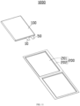
- An embodiment of this application further provides an electrochemical apparatus 1000.
- the electrochemical apparatus 1000 includes a housing 200 and the electrode assembly 100 in any one of the embodiments above. At least a portion of the electrode assembly 100 is provided in the housing 200.
- the first electrode tab 10 of the electrode assembly 100 does not go beyond the first active substance layer 20b of the first section 21 and the second section 22 in the third direction Z, thus improving the spatial utilization rate of the electrode assembly 100 in the third direction Z, and improving the energy density of the electrochemical apparatus 1000.
- the first dissociative portion 231 is dissociated from the first section 21 and the second section 22, which is conducive to reducing the deformation of the third section 23 when the first dissociative portion 231 moves along the third direction Z, thus reducing the risk that the first active substance layer 20b at the boundary of the area without the first active substance layer 20b and the area with the first active substance layer 20b is separated from the first current collector 20a, and improving the reliability of the electrochemical apparatus 1000.
- the housing 200 includes a first portion 201 and a second portion 202 extending outwards from the first portion 201.
- the wound structure formed by stacking and winding the first electrode plate 20, the separator 40 and the second electrode plate 30 is accommodated in the first portion 201.
- the first electrode tab 10 and the second electrode tab 50 extend out of the housing 200 from the second portion 202.
- the housing 200 includes an aluminum-plastic film
- the electrochemical apparatus 1000 includes a flexible battery.
- the electrochemical apparatus 1000 adopts the technical solution in any embodiment of the electrode assembly 100, it has at least the beneficial effects brought by the technical solution in any embodiment of the electrode assembly 100, which will not be repeated here.
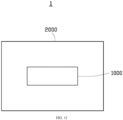
- An embodiment of this application further provide an electrical device 1.
- the electrical device 1 includes a device main body 2000 and the electrochemical apparatus 1000 in any one of the embodiments above.
- the electrochemical apparatus 1000 is mounted to the device main body 2000.
- the energy density and reliability of the electrochemical apparatus 1000 are improved, which is conducive to improving the use duration after charging and the service life of the electrical device 1, and reducing the failure rate of the electrical device 1.
- the electrical device 1 adopts the technical solution in any embodiment of the electrochemical apparatus 1000, it has at least the beneficial effects brought by the technical solution in any embodiment of the electrochemical apparatus 1000, which will not be repeated here.
- the electrical device 1 may be a smartphone, a laptop computer, head-mounted VR glasses, a smart bracelet, a drone, a cleaning robot, an electric car, an electric two-wheeled vehicle, an electric motorcycle, or a wireless vacuum cleaner.
Landscapes
- Chemical & Material Sciences (AREA)
- Chemical Kinetics & Catalysis (AREA)
- Electrochemistry (AREA)
- General Chemical & Material Sciences (AREA)
- Engineering & Computer Science (AREA)
- Manufacturing & Machinery (AREA)
- Battery Electrode And Active Subsutance (AREA)
- Connection Of Batteries Or Terminals (AREA)
- Secondary Cells (AREA)
- Electric Double-Layer Capacitors Or The Like (AREA)
Abstract
Description
- This application relates to the technical field of energy storage, in particular to an electrode assembly, an electrochemical apparatus and an electrical device.
- In order to adapt to the miniaturization and portability of electronic devices such as mobile phones, laptop computers and wearable devices, as well as the development trend of long endurance of power equipment such as electric vehicles and electric motorcycles, it is required that the cell should develop towards the direction of increasing energy density. Improving the spatial utilization rate of the internal structure of the cell is an important means to improve the energy density of the cell.
- At present, the electrode assembly of the wound cell includes an electrode plate and an electrode tab connected to the electrode plate. The method for the connection between the electrode tab and the electrode plate is usually to remove the active substance layer on the electrode plate to obtain an empty foil area in which the current collector is exposed, and to weld the electrode tab to the empty foil area. Since the electrode tab itself occupies a certain thickness, in a case that the active substance layer on the electrode plate is thin, the electrode tab may go beyond the electrode plate in the thickness direction, resulting in low space utilization rate of the electrode assembly in the thickness direction.
- In view of this, it is necessary to provide an electrode assembly conducive to improving the spatial utilization rate.
- Some embodiments of this application provide an electrode assembly, including a first electrode tab, a first electrode plate, a second electrode plate and a separator, the separator being located between the first electrode plate and the second electrode plate, the first electrode plate, the separator and the second electrode plate being stacked and wound, the first electrode plate including a first current collector and a first active substance layer, the first current collector including a first section, a second section and a third section, a surface of the first section being at least partially provided with the first active substance layer, a surface of the second section being at least partially provided with the first active substance layer; along a first direction, the third section being located between the first section and the second section; along a second direction, the third section including a first dissociative portion and a first connection portion connected sequentially, the first connection portion connecting the first section and the second section; along the first direction, one side of the first dissociative portion being dissociated from the first section, the side of the first dissociative portion opposite to the first section being dissociated from the second section; the first dissociative portion having a first empty foil area without the first active substance layer, one side of the first empty foil area in a third direction being connected to the first electrode tab, the third direction being a thickness direction of the first electrode plate, every two of the third direction, the first direction and the second direction being perpendicular to each other.
- In the embodiments above, the first dissociative portion is dissociated from the first section and the second section, which is conducive to making the first dissociative portion move along the third direction relative to the first section and the second section, thus improving the moving distance of the first electrode tab along the third direction relative to the first section and the second section, enabling the first electrode tab to not go beyond the first active substance layer of the first section and the second section in the third direction, and improving the spatial utilization rate of the electrode component in the third direction. In addition, the first electrode tab is connected to the first dissociative portion and the first dissociative portion is dissociated from the first section and the second section, which is conducive to reducing the deformation of the third section when the first dissociative portion moves along the third direction, thus reducing the risk that the first active substance layer at the boundary of the area without the first active substance layer and the area with the first active substance layer is separated from the first current collector.
- In some embodiments, a first gap is provided between the first dissociative portion and the first section, and a second gap is provided between the first dissociative portion and the second section.
- In the embodiments above, the first dissociative portion is dissociated from the first section through the first gap and the first dissociative portion is dissociated from the second section through the second gap, which is conducive to reducing the cut-off part of the first electrode plate and increasing the retained part of the first electrode plate, thus improving the energy density of the electrode assembly.
- In some embodiments, the first gap and the second gap both extend along the second direction.
- In the embodiments above, the first gap and the second gap both extend along the second direction, which is conducive to making the shape of the first dissociative portion more regular, thus facilitating the connection between the first electrode tab and the first empty foil area of the first dissociative portion.
- In some embodiments, an extension direction of the first gap and an extension direction of the second gap are both inclined relative to the second direction; along the second direction, a distance between the first gap and the first electrode tab in the first direction gradually decreases, and a distance between the second gap and the first electrode tab in the first direction gradually decreases.
- In the embodiments above, the distance between the first gap and the first electrode tab in the first direction gradually decreases, and the distance between the second gap and the first electrode tab in the first direction gradually decreases, which is conducive to reducing the risk that the separation tool such as cutting knife or punching head interferes with the first electrode tab adhesive in the process of forming the first gap and the second gap.
- In some embodiments, when viewed along the third direction, a projection of the first electrode tab on the first electrode plate has a length of Wi along the second direction, and along the second direction, a length of the first dissociative portion is W2, which satisfies W1/2≤W2≤3W1/2.
- In the embodiments above, W1 and W2 satisfy W1/2≤W2≤3W1/2, which is conducive to making the moving distance of the first dissociative portion along the third direction satisfy the requirement that the first electrode tab moves to a position in the third direction without going beyond the first active substance layer of the first section and the second section, and also to reducing the risk that the third section is separated from the first section and the second section since the length of the first gap and the second gap along the second direction is too large.
- In some embodiments, the first dissociative portion has a first wall facing to the first section, the first section has a second wall facing to the first dissociative portion, a third wall is connected between the first wall and the second wall, and along the first direction, the distance between the first wall and the second wall is D1, which satisfies W2≥D1≥W2/20.
- In the embodiments above, a gap is formed between the first dissociative portion and the first section. When the first electrode plate is stressed, D1 and W2 are enabled to satisfy W2≥D1≥W2/20, which is conducive to reducing the risk of cracking at the third wall due to stress concentration at the third wall since D1 is too small. In addition, by limiting D1≤W2, D1 is not too large, which is conducive to reducing the risk that the part of the first electrode plate originally provided with the first active substance layer is removed, thus improving the energy density of the electrode assembly.
- In some embodiments, the first dissociative portion has a first wall facing to the first section, the first section has a second wall facing to the first dissociative portion, a third wall is connected between the first wall and the second wall, and the third wall is a concave arc-shaped wall.
- In the embodiments above, the third wall is a concave arc-shaped wall, which is conducive to reducing the stress on the third wall, thus reducing the risk of cracking at the third wall.
- In some embodiments, along the first direction, the distance between the first wall and the second wall is D1, and a diameter corresponding to the third wall is T1, which satisfies D1≤T1≤5D1.
- In the embodiments above, the diameter T1 corresponding to the third walls satisfies D1≤T1≤5D1, which can achieve the effect that the third wall is an arc-shaped wall, and is conducive to reducing the risk of stress concentration since the transition between the third wall and the first wall is not mild enough due to the excessive curvature of the third wall, or to reducing the risk of stress concentration since the transition between the third wall and the second wall is not mild enough.
- In some embodiments, the first dissociative portion further has a collection layer area with the first active substance layer, and along the second direction, the collection layer area is located between the first connection portion and the first empty foil area.
- In the embodiments above, the provided collection layer area is conducive to increasing the area of the first active substance layer, thus improving the energy density of the electrode assembly. In addition, the collection layer area is provided between the first connection portion and the first empty foil area, rather than on the side of the first empty foil area facing to the first section or the side of the first empty foil area facing to the second section, thus reducing the risk that the first active substance layer in the collection layer area interferes with the movement of the first electrode tab in the third direction, and ensuring that the first electrode tab does not go beyond the first active substance layer of the first section and the second section in the third direction.
- In some embodiments, the surface of the first section has a first side empty foil area without the first active substance layer, and along the first direction, the first side empty foil area is located on one side of the first empty foil area, and the first side empty foil area is dissociated from the first empty foil area.
- In the embodiments above, the first side empty foil area is provided, so that the two opposite sides of the part where the first dissociative portion is separated from the first section are not provided with the first active substance layer, thus reducing the risk that the first active substance layer interferes with the separation process, and facilitating the separation between the first dissociative portion and the first section. In the actual production process, common methods such as cutting, punching and laser may be used to achieve the separation between the first dissociative portion and the first section.
- In some embodiments, the first dissociative portion and the first connection portion are not provided with the first active substance layer.
- In the embodiments above, the first dissociative portion and the first connection portion are not provided with the first active substance layer, so that the first electrode tab can extend out of the first electrode plate along the second direction, thus making the same first electrode tab have two positions from which the polarity of the first electrode plate can be led out.
- In addition, this application further provides an electrochemical apparatus capable of improving energy density and reliability.
- Some embodiments of this application provide an electrochemical apparatus, including a housing and the electrode assembly in any one of the embodiments above, at least a portion of the electrode assembly being provided in the housing.
- In the embodiments above, the first electrode tab of the electrode assembly does not go beyond the first active substance layer of the first section and the second section in the third direction, thus improving the spatial utilization rate of the electrode assembly in the third direction, and improving the energy density of the electrochemical apparatus. The first dissociative portion is dissociated from the first section and the second section, which is conducive to reducing the deformation of the third section when the first dissociative portion moves along the third direction, thus reducing the risk that the first active substance layer at the boundary of the area without the first active substance layer and the area with the first active substance layer is separated from the first current collector, and improving the reliability of the electrochemical apparatus.
- In addition, this application further provides an electrical device capable of improving the use duration after charging and the service life.
- Some embodiments of this application provide an electrical device, including a device main body and the electrochemical apparatus in any one of the embodiments above, the electrochemical apparatus being mounted to the device main body.
- In the embodiments above, the energy density and reliability of the electrochemical apparatus are improved, which is conducive to improving the use duration after charging and the service life of the electrical device, and reducing the failure rate of the electrical device.
- In this application, an electrode assembly includes a first electrode tab, and a first electrode plate, a second electrode plate and a separator which are wound. The first electrode plate includes a first section, a second section and a third section. Along the second direction, the third section includes a first dissociative portion and a first connection portion connected sequentially, Along the first direction, one side of the first dissociative portion is dissociated from the first section, the side of the first dissociative portion opposite to the first section is dissociated from the second section, and a first empty foil area on the first dissociative portion is connected with the first electrode tab. The first dissociative portion being dissociated from the first section and the second section is conducive to increasing the moving distance of the first electrode tab along the third direction relative to the first section and the second section, so that the first electrode tab does not go beyond the first active substance layer of the first section and the second section in the third direction, thus improving the spatial utilization rate of the electrode assembly in the third direction. In addition, the first dissociative portion being dissociated from the first section and the second section is conducive to reducing the deformation of the third section when the first dissociative portion moves along the third direction, thus reducing the risk that the first active substance layer at the boundary of the area without the first active substance layer and the area with the first active substance layer is separated from the first current collector.
-
-
FIG. 1 illustrates a sectional schematic diagram of an electrode assembly according to an embodiment of this application. -
FIG. 2 illustrates a partial schematic diagram of an electrode assembly according to an embodiment of this application. -
FIG. 3 illustrates a partial side view of an electrode assembly in the existing technology. -
FIG. 4 illustrates a partial side view of an electrode assembly according to an embodiment of this application. -
FIG. 5 illustrates a partial schematic diagram of an electrode assembly according to an embodiment of this application. -
FIG. 6 illustrates a partial schematic diagram of an electrode assembly according to an embodiment of this application. -
FIG. 7 illustrates a partial schematic diagram of an electrode assembly according to an embodiment of this application. -
FIG. 8 illustrates a partial schematic diagram of an electrode assembly according to an embodiment of this application. -
FIG. 9 illustrates a partial side view of an electrode assembly according to an embodiment of this application. -
FIG. 10 illustrates a partial side view of an electrode assembly according to an embodiment of this application. -
FIG. 11 illustrates an exploded schematic diagram of an electrochemical apparatus according to an embodiment of this application. -
FIG. 12 illustrates a schematic diagram of an electrical device according to an embodiment of this application. - Description of reference signs of main components: 100-electrode assembly, 10-first electrode tab, 11-first metal part, 12-first electrode tab adhesive, 20-first electrode plate, 21-first section, 211-second wall, 212-first side empty foil area, 22-second section, 221-second side empty foil area, 23-third section, 231-first dissociative portion, 2311-first empty foil area, 2312-first wall, 2313-collection layer area, 232-first connection portion, 233-first gap, 234-second gap, 24-third wall, 20a-first current collector, 20b-first active substance layer, 30-second electrode plate, 31-fourth section, 32-fifth section, 33-sixth section, 331-second dissociative portion, 3311-second empty foil area, 332-second connection portion, 30a-second current collector, 30b-second active substance layer, 40-separator, 50-second electrode tab, 51-second metal part, 52-second electrode tab adhesive, 60-first insulating adhesive, 70-second insulating adhesive, 101-cutting knife, 200-housing, 201-first portion, 202-second portion, 1000-electrochemical apparatus, 2000-device main body, 1-electrical device, X-first direction, Y-second direction, Z-third direction.
- The technical solution in the embodiments of this application will be described below with reference to the drawings in the embodiments of this application. Obviously, the described embodiments are only a part of the embodiments of this application, not all of them.
- It should be noted that when a component is considered to be "connected" to another component, it may be directly connected to another component or there may be an intermediate component at the same time. When a component is considered "provided" on another component, it may be directly provided on another component or there may be an intermediate component at the same time. The terms "top", "bottom", "up", "down", "left", "right", "front", "back", and similar expressions used herein are for descriptive purposes only.
- The term "perpendicular" is used to describe the ideal state between two components. In actual production or use, there may be an approximately perpendicular state between two components. For example, by describing in conjunction with numerical values, "perpendicular" may refer to that an included angle is between two straight lines is 90°±10°, "perpendicular" may also refer to that a dihedral angle between two planes is 90°±10°, and "perpendicular" may also refer to that an included angle between a straight line and a plane is 90°±10°. The two components described as "perpendicular" may not be absolute straight lines or planes, but may be roughly straight lines or planes. From a macro perspective, if the overall extension direction is straight lines or planes, the components may be considered as "straight lines" or "planes".
- It should be noted that when a parameter is more than, equal to, or less than a certain endpoint value, it should be understood that a tolerance of ±5% is allowed for the endpoint value.
- Unless otherwise defined, all technical and scientific terms used herein have the same meanings as those commonly understood by technical personnel in the technical field to which this application belongs. The terms used in the description of this application herein are only for the purpose of describing specific embodiments and are not intended to limit this application.
- This application discloses an electrode assembly. The electrode assembly includes a first electrode tab, a first electrode plate, a second electrode plate and a separator. The separator is located between the first electrode plate and the second electrode plate. The first electrode plate, the separator and the second electrode plate are stacked and wound. The first electrode plate includes a first current collector and a first active substance layer. The first current collector includes a first section, a second section and a third section. A surface of the first section is at least partially provided with the first active substance layer. A surface of the second section is at least partially provided with the first active substance layer. Along a first direction, the third section is located between the first section and the second section. Along a second direction, the third section includes a first dissociative portion and a first connection portion connected sequentially. The first connection portion connects the first section and the second section. Along the first direction, one side of the first dissociative portion is dissociated from the first section, and the side of the first dissociative portion opposite to the first section is dissociated from the second section. The first dissociative portion has a first empty foil area without the first active substance layer. One side of the first empty foil area in a third direction is connected to the first electrode tab. The third direction is a thickness direction of the first electrode plate. Every two of the third direction, the first direction and the second direction are perpendicular to each other.
- The first dissociative portion is dissociated from the first section and the second section, which is conducive to making the first dissociative portion move along the third direction relative to the first section and the second section, thus improving the moving distance of the first electrode tab along the third direction relative to the first section and the second section, enabling the first electrode tab to not go beyond the first active substance layer of the first section and the second section in the third direction, and improving the spatial utilization rate of the electrode assembly in the third direction. In addition, the first electrode tab is connected to the first dissociative portion and the first dissociative portion is dissociated from the first section and the second section, which is conducive to reducing the deformation of the third section when the first dissociative portion moves along the third direction, thus reducing the risk that the first active substance layer at the boundary of the area without the active substance layer and the area with the active substance layer is separated.
- Some embodiments of this application will be described below with reference to the drawings. Without causing conflict, the following embodiments and the features in the embodiments may be combined with each other.
- Please refer to
FIG. 1 . An embodiment of this application provides anelectrode assembly 100. Theelectrode assembly 100 includes afirst electrode tab 10, afirst electrode plate 20, asecond electrode plate 30 and aseparator 40. Theseparator 40 is located between thefirst electrode plate 20 and thesecond electrode plate 30. Thefirst electrode plate 20, theseparator 40 and thesecond electrode plate 30 are stacked and wound. Thefirst electrode tab 10 is connected to thefirst electrode plate 20. - The polarity of the
first electrode tab 10 can be positive or negative, and the polarity of thefirst electrode tab 10 is the same as that of thefirst electrode plate 20. - In some embodiments, referring to
FIG. 2 , thefirst electrode tab 10 includes afirst metal part 11 and a firstelectrode tab adhesive 12. Thefirst metal part 11 is connected to thefirst electrode plate 20. The material of thefirst metal part 11 is the same as that of thefirst electrode plate 20. The firstelectrode tab adhesive 12 is coated on thefirst metal part 11. - In some embodiments, the
first metal part 11 and thefirst electrode plate 20 are connected by welding. The welding method may be resistance welding, laser welding, arc welding or ultrasonic welding. - In some embodiments, the
first electrode plate 20 may be a positive electrode plate or a negative electrode plate, thesecond electrode plate 30 may be a positive electrode plate or a negative electrode plate, and the polarity of thefirst electrode plate 20 is opposite to that of thesecond electrode plate 30. For example, thefirst electrode plate 20 is a positive electrode plate, and thesecond electrode plate 30 is a negative electrode plate. For another example, thefirst electrode plate 20 is a negative electrode plate, and thesecond electrode plate 30 is a positive electrode plate. - In some embodiments, the
first electrode plate 20 includes a firstcurrent collector 20a and a firstactive substance layer 20b. The firstactive substance layer 20b is provided on a surface of the firstcurrent collector 20a. Thesecond electrode plate 30 includes a secondcurrent collector 30a and a secondactive substance layer 30b. The secondactive substance layer 30b is provided on a surface of the secondcurrent collector 30a. Each of the firstcurrent collector 20a and the secondcurrent collector 30a includes a metal layer. A material of the firstactive substance layer 20b is different from that of the secondactive substance layer 30b. - The positive electrode plate may be combined onto a metal layer of at least one of aluminum, platinum, nickel, tantalum, titanium and the like by using positive electrode slurry. The positive electrode slurry combined onto the metal layer forms a positive electrode active substance layer. The negative electrode plate may be combined onto a metal layer of at least one of copper, platinum, nickel, tantalum, titanium and the like by using negative electrode slurry. The negative electrode slurry combined onto the metal layer forms a negative electrode active substance layer. As an example, the
first electrode plate 20 is a positive electrode plate, the firstcurrent collector 20a includes a metal aluminum layer, thesecond electrode plate 30 is a negative electrode plate, and the secondcurrent collector 30a includes a metal copper layer. - In some embodiments, the first
active substance layer 20b is coated on a surface of the firstcurrent collector 20a through a coating process, and the secondactive substance layer 30b is coated on a surface of the secondcurrent collector 30a through a coating process. - Referring to
FIG. 1 , theseparator 40 is provided between thefirst electrode plate 20 and thesecond electrode plate 30 to separate thefirst electrode plate 20 and thesecond electrode plate 30 with different polarities. - In some embodiments, the
separator 40 is a film material that can insulate, such as a polyethylene film, a polypropylene film, a polyester film or a polyimide film, so as to separate thefirst electrode plate 20 and thesecond electrode plate 30. - Referring to
FIG. 1 andFIG. 2 , the firstcurrent collector 20a includes afirst section 21, asecond section 22, and athird section 23. Along a first direction X, thethird section 23 is located between thefirst section 21 and thesecond section 22. One of thefirst section 21 and thesecond section 22 serves as a starting section for the winding of thefirst electrode plate 20, while the other of thefirst section 21 and thesecond section 22 serves as an ending section for the winding of thefirst electrode plate 20. The surfaces of thefirst section 21 and thesecond section 22 are at least partially provided with the firstactive substance layer 20b. Thethird section 23 is connected to thefirst electrode tab 10. - In the existing technology, referring to
FIG. 3 , thethird section 23 is provided with a firstempty foil area 2311 without the firstactive substance layer 20b. The firstempty foil area 2311 is connected to thefirst section 21 and thesecond section 22. Thefirst electrode tab 10 is connected to the firstempty foil area 2311. Thefirst electrode tab 10 goes beyond the firstactive substance layer 20b of thefirst section 21 and thesecond section 22 along the thickness direction of the first electrode plate. In the first electrode plate of a wound structure, thefirst electrode tab 10 is squeezed along the thickness direction of the first electrode plate, causing thefirst electrode tab 10 to move a certain distance along the thickness direction of the first electrode plate. Since the firstempty foil area 2311 is connected to thefirst section 21 and thesecond section 22, the moving distance of thefirst electrode tab 10 is limited by thefirst section 21 and thesecond section 22, Therefore, thefirst electrode tab 10 still goes beyond the firstactive substance layer 20b of thefirst section 21 and thesecond section 22 along the thickness direction of the first electrode plate, and the movement of thefirst electrode tab 10 drives the deformation of thethird section 23, which easily causes the firstactive substance layer 20b at the boundary of the firstempty foil area 2311 to separate. - In this application, referring to
FIG. 2 andFIG. 4 , thethird section 23 includes a firstdissociative portion 231 and afirst connection portion 232 sequentially connected along a second direction Y. Thefirst connection portion 232 connects thefirst section 21 and thesecond section 22. Along the first direction X, one side of the firstdissociative portion 231 is dissociated from thefirst section 21, and the side of the firstdissociative portion 231 opposite to thefirst section 21 is dissociated from thesecond section 22, which is conducive to making the firstdissociative portion 231 move in a third direction Z relative to thefirst section 21 and thesecond section 22. The third direction Z is a thickness direction of the first electrode plate. Every two of the third direction Z, the first direction X and the second direction Y are perpendicular to each other. The surface of the firstdissociative portion 231 has a firstempty foil area 2311 without the firstactive substance layer 20b. One side of the firstempty foil area 2311 in the third direction Z is connected with thefirst electrode tab 10, which is conducive to increasing the moving distance of thefirst electrode tab 10 along the third direction Z relative to thefirst section 21 and thesecond section 22. In the first electrode plate of a wound structure, thefirst electrode tab 10 is squeezed along the third direction Z or in a direction opposite to the third direction Z, causing thefirst electrode tab 10 to move along the third direction Z until thefirst electrode tab 10 does not go beyond the firstactive substance layer 20b of thefirst section 21 and thesecond section 22 in the third direction Z. Thefirst electrode tab 10 not going beyond the firstactive substance layer 20b of thefirst section 21 and thesecond section 22 in the third direction Z is conducive to improving the spatial utilization rate of theelectrode assembly 100 in the third direction Z. In addition, thefirst electrode tab 10 is connected to the firstdissociative portion 231 and the firstdissociative portion 231 is dissociated from thefirst section 21 and thesecond section 22, which is conducive to reducing the deformation of thethird section 23 when the firstdissociative portion 231 moves along the third direction Z, thus reducing the risk that the firstactive substance layer 20b at the boundary of the area without the firstactive substance layer 20b and the area with the firstactive substance layer 20b is separated from the firstcurrent collector 20a. - In some embodiments, referring to
FIG. 2 , afirst gap 233 is provided between the firstdissociative portion 231 and thefirst section 21, and asecond gap 234 is provided between the firstdissociative portion 231 and thesecond section 22. In this embodiment, the firstdissociative portion 231 is dissociated from thefirst section 21 through thefirst gap 233, and the firstdissociative portion 231 is dissociated from thesecond section 22 through thesecond gap 234, which is conducive to reducing the cut-off part of thefirst electrode plate 20, increasing the retained part of thefirst electrode plate 20, and improving the energy density of theelectrode assembly 100. - In some embodiments, referring to
FIG. 1 andFIG. 2 , thefirst gap 233 and thesecond gap 234 are formed by using a cuttingknife 101 to cut thefirst electrode plate 20 along the second direction Y and cut off a part of thefirst electrode plate 20, so that thefirst gap 233 and thesecond gap 234 are formed in thefirst electrode plate 20. Cutting thefirst electrode plate 20 along the second direction Y is conducive to reducing the risk of deformation under stress when thefirst electrode plate 20 is cut. - In some embodiments, the
first gap 233 and thesecond gap 234 are formed by using the cuttingknife 101 to cut thefirst electrode plate 20 along a direction forming an included angle with the second direction Y and perpendicular to the third direction Z, and cut off a part of thefirst electrode plate 20, so that thefirst gap 233 and thesecond gap 234 are formed in thefirst electrode plate 20. Cutting thefirst electrode plate 20 in a direction forming an included angle with the second direction Y and perpendicular to the third direction Z is conducive to reducing the risk of deformation under stress when thefirst electrode plate 20 is cut. - In some embodiments, the
first gap 233 and thesecond gap 234 are formed by using the cuttingknife 101 to cut thefirst electrode plate 20 along the third direction Z, and cut off a part of thefirst electrode plate 20, so that thefirst gap 233 and thesecond gap 234 are formed in thefirst electrode plate 20. In the embodiment in which thefirst electrode tab 10 includes afirst metal part 11 and a firstelectrode tab adhesive 12, thefirst metal part 11 of thefirst electrode tab 10 is welded to thefirst electrode plate 20. The firstelectrode tab adhesive 12 is located on one side of thefirst electrode plate 20 along a direction opposite to the second direction Y. Cutting thefirst electrode plate 20 along the third direction Z is conducive to reducing the risk that the cuttingknife 101 interferes with the first electrode tab adhesive 12 in the cutting process of thefirst gap 233 and thesecond gap 234. - In some embodiments, the cutting
knife 101 is placed at a position to be dissociated of thefirst electrode plate 20, and thefirst electrode plate 20 is wound to wind the cuttingknife 101 into the wound structure. The cuttingknife 101 is extracted from the wound structure and cuts off a part of thefirst electrode plate 20, so that thefirst gap 233 and thesecond gap 234 are formed in thefirst electrode plate 20. Cutting thefirst electrode plate 20 after winding is conducive to reducing the risk that the cut-off part of thefirst electrode plate 20 punctures theseparator 40 in the winding process. - In some embodiments, the
first gap 233 and thesecond gap 234 are formed by using a laser emission tool to emit laser towards thefirst electrode plate 20 along the second direction Y, or in a direction forming an included angle with the second direction Y and perpendicular to the third direction Z. The laser melts a part of thefirst electrode plate 20, thus forming thefirst gap 233 and thesecond gap 234 in thefirst electrode plate 20. - In some embodiments, the
first gap 233 and thesecond gap 234 are formed by using the laser emission tool to emit laser towards thefirst electrode plate 20 along the third direction Z, and then moving the laser emission tool along the second direction Y or in a direction forming an included angle with the second direction Y and perpendicular to the third direction Z. The laser melts a part of thefirst electrode plate 20, thus forming thefirst gap 233 and thesecond gap 234 in thefirst electrode plate 20. - It should be noted that the methods for forming the
first gap 233 and thesecond gap 234 are not limited to the method of cutting by using the cuttingknife 101 and the laser melting method, and may be other methods such as punching that can form thefirst gap 233 and thesecond gap 234, which are omitted here. - In some embodiments, referring to
FIG. 2 , thefirst gap 233 and thesecond gap 234 both extend along the second direction Y, which is conducive to making the shape of the firstdissociative portion 231 more regular, thus facilitating the connection between thefirst electrode tab 10 and the firstempty foil area 2311 of the firstdissociative portion 231. - In some embodiments, referring to
FIG. 5 , an extension direction of thefirst gap 233 and an extension direction of thesecond gap 234 are both inclined relative to the second direction Y, and along the second direction Y, the distance between thefirst gap 233 and thefirst electrode tab 10 in the first direction X gradually decreases, and the distance between thesecond gap 234 and thefirst electrode tab 10 in the first direction X gradually decreases. In the embodiment in which thefirst electrode tab 10 includes afirst metal part 11 and a firstelectrode tab adhesive 12, thefirst metal part 11 of thefirst electrode tab 10 is welded to thefirst electrode plate 20. Along a direction opposite to the second direction Y, the firstelectrode tab adhesive 12 is located on one side of thefirst electrode plate 20. By setting the extension directions of thefirst gap 233 and thesecond gap 234 according to the above embodiment, it is conducive to reducing the risk that the cuttingknife 101 or other separation tool such as punching head interferes with the first electrode tab adhesive 12 in the cutting process of thefirst gap 233 and thesecond gap 234. - In some embodiments, referring to
FIG. 6 , when viewed along the third direction Z, a projection of thefirst electrode tab 10 on thefirst electrode plate 20 has a length of Wi along the second direction Y, and along the second direction Y, the length of the firstdissociative portion 231 is W2, which satisfies formula 1: W1/2≤W2≤3W1/2. The length W2 of the firstdissociative portion 231 along the second direction Y is equal to the length of thefirst gap 233 and thesecond gap 234 along the second direction Y. In a case that W1 and W2 satisfyformula 1, it is conducive to making the moving distance of the firstdissociative portion 231 along the third direction Z satisfy the requirement that thefirst electrode tab 10 moves to a position in the third direction Z without going beyond the firstactive substance layer 20b of thefirst section 21 and thesecond section 22, also to reducing the risk that thethird section 23 is separated from thefirst section 21 and thesecond section 22 since the length of thefirst gap 233 and thesecond gap 234 along the second direction Y is too large. - In some embodiments, referring to
FIG. 6 and FIG. 7 , the firstdissociative portion 231 has afirst wall 2312 facing to thefirst section 21, thefirst section 21 has asecond wall 211 facing to the firstdissociative portion 231, and athird wall 24 is connected between thefirst wall 2312 and thesecond wall 211. Along the first direction X, the distance between thefirst wall 2312 and thesecond wall 211 is D1, which satisfies formula 2: W2≥D1≥W2/20. In a case that thefirst electrode plate 20 is stressed, making D1 and W2 satisfy formula 2 is conducive to reducing the risk of cracking at the third wall due to stress concentration at thethird wall 24 since D1 is too small. In addition, by limiting D1≤W2, D1 is not too large, which reduces the risk that the part of thefirst electrode plate 20 originally provided with the first active substance layer is removed, thus improving the energy density of theelectrode assembly 100. - In some embodiments, referring to
FIG. 6 and FIG. 7 , the firstdissociative portion 231 has afirst wall 2312 facing to thefirst section 21, thefirst section 21 has asecond wall 211 facing to the firstdissociative portion 231, athird wall 24 is connected between thefirst wall 2312 and thesecond wall 211, and thethird wall 24 is a concave arc-shaped wall. In a case that thethird section 23 is stressed, thethird wall 24 being a concave arc-shaped wall is conducive to reducing the stress on thethird wall 24, thus reducing the risk of cracking at thethird wall 24. - In some embodiments, referring to
FIG. 6 and FIG. 7 , along the first direction X, the distance between thefirst wall 2312 and thesecond wall 211 is D1, and the diameter corresponding to thethird wall 24 is T1, which satisfies formula 3: D1≤T1≤5D1. In a case that the diameter T1 corresponding to thethird wall 24 satisfies formula 3, it can achieve the effect that thethird wall 24 is an arc-shaped wall, and is conducive to reducing the risk of stress concentration since the transition between thethird wall 24 and thefirst wall 2312 is not mild enough due to the excessive curvature of thethird wall 24, or to reducing the risk of stress concentration since the transition between thethird wall 24 and thesecond wall 211 is not mild enough. - In some embodiments, referring to
FIG. 6 , the firstdissociative portion 231 further has acollection layer area 2313 with the firstactive substance layer 20b, and along the second direction Y, thecollection layer area 2313 is located between thefirst connection portion 232 and the firstempty foil area 2311. Providing thecollection layer area 2313 on the firstdissociative portion 231 is conducive to increasing the area of the firstactive substance layer 20b, thus improving the energy density of theelectrode assembly 100. In addition, thecollection layer area 2313 is provided between thefirst connection portion 232 and the firstempty foil area 2311, rather than on the side of the firstempty foil area 2311 facing to thefirst section 21 or the side of the firstempty foil area 2311 facing to thesecond section 22, thus reducing the risk that the firstactive substance layer 20b in thecollection layer area 2313 interferes with the movement of thefirst electrode tab 10 in the third direction Z, and ensuring that thefirst electrode tab 10 does not go beyond the firstactive substance layer 20b of thefirst section 21 and thesecond section 22 in the third direction Z. - In some embodiments, referring to
FIG. 6 , the surface of thefirst section 21 has a first sideempty foil area 212 without the firstactive substance layer 20b, and along the first direction X, the first sideempty foil area 212 is located on one side of the firstempty foil area 2311, and the firstempty foil area 2311 is dissociated from the first sideempty foil area 212. The first sideempty foil area 212 is provided, so that the two opposite sides of the part where the firstdissociative portion 231 is separated from thefirst section 21 are not provided with the firstactive substance layer 20b, thus reducing the risk that the firstactive substance layer 20b interferes with the separation tool such as the cuttingknife 101 or punching head, and facilitating the formation of thefirst gap 233 and thesecond gap 234. - In some embodiments, referring to
FIG. 6 , the surface of thesecond section 22 has a second sideempty foil area 221 without the firstactive substance layer 20b, and along the first direction X, the second sideempty foil area 221 is located on one side of the firstempty foil area 2311 opposite to the first sideempty foil area 212, and the firstempty foil area 2311 is dissociated from the second sideempty foil area 221. The second sideempty foil area 221 is provided, so that the two opposite sides of the part where the firstdissociative portion 231 is separated from thesecond section 22 are not provided with the firstactive substance layer 20b, thus reducing the risk that the firstactive substance layer 20b interferes with the separation tool such as the cuttingknife 101 or punching head, and facilitating the formation of thefirst gap 233 and thesecond gap 234. - In some embodiments, the first
dissociative portion 231 and thefirst connection portion 232 are not provided with the firstactive substance layer 20b, so that thefirst electrode tab 10 can extend out of thefirst electrode plate 20 along the second direction Y, thus making the samefirst electrode tab 10 have two positions from which the polarity of thefirst electrode plate 20 can be led out. - In some embodiments, referring to
FIG. 1 andFIG. 8 , theelectrode assembly 100 further includes asecond electrode tab 50, and thesecond electrode tab 50 is connected to thesecond electrode plate 30. The polarity of thesecond electrode tab 50 may be positive or negative, and the polarity of thesecond electrode tab 50 is opposite to that of thefirst electrode tab 10. For example, thefirst electrode tab 10 is a positive electrode tab, and thesecond electrode tab 50 is a negative electrode tab. For another example, thefirst electrode tab 10 is a negative electrode tab, and thesecond electrode tab 50 is a positive electrode tab. - In some embodiments, referring to
FIG. 8 , thesecond electrode tab 50 includes asecond metal part 51 and a secondelectrode tab adhesive 52. Thesecond metal part 51 is connected to thesecond electrode plate 30. The material of thesecond metal part 51 is the same as that of thesecond electrode plate 30. The secondelectrode tab adhesive 52 is coated on thesecond metal part 51. Thesecond electrode tab 50 and thesecond electrode plate 30 are connected by welding such as resistance welding, laser welding, arc welding or ultrasonic welding. - In some embodiments, referring to
FIG. 1 andFIG. 8 , the secondcurrent collector 30a includes afourth section 31, afifth section 32 and asixth section 33. Along the first direction X, thesixth section 33 is located between thefourth section 31 and thefifth section 32. One of thefourth section 31 and thefifth section 32 serves as a starting section for the winding of thesecond electrode plate 30, while the other of thefourth section 31 and thefifth section 32 serves as an ending section for the winding of thesecond electrode plate 30. Both thefourth section 31 and thefifth section 32 are at least partially provided with a secondactive substance layer 30b. Thesixth section 33 is connected to thesecond electrode tab 50. Thesixth section 33 includes a seconddissociative portion 331 and asecond connection portion 332 sequentially connected along the second direction Y. Thesecond connection portion 332 connects thefourth section 31 and thefifth section 32. Along the first direction X, one side of the seconddissociative portion 331 is dissociated from thefourth section 31, and the side of the seconddissociative portion 331 opposite to thefourth section 31 is dissociated from thefifth section 32. The seconddissociative portion 331 has a secondempty foil area 3311 without the secondactive substance layer 30b. One side of the secondempty foil area 3311 in the third direction Z is connected to thesecond electrode tab 50. - In the embodiments above, along the first direction X, one side of the second
dissociative portion 331 is dissociated from thefourth section 31, which is conducive to making the seconddissociative portion 331 move along the third direction Z relative to thefirst section 21 and thesecond section 22, thus increasing the moving distance of thesecond electrode tab 50 along the third direction Z relative to thefourth section 31 and thefifth section 32. In thesecond electrode plate 30 of the wound structure, thesecond electrode tab 50 is squeezed along the third direction Z or in a direction opposite to the third direction Z, causing thesecond electrode tab 50 to move along the third direction Z until thesecond electrode tab 50 does not go beyond the secondactive substance layer 30b of thefourth section 31 and thefifth section 32 in the third direction Z. Thesecond electrode tab 50 not going beyond the secondactive substance layer 30b of thefourth section 31 and thefifth section 32 in the third direction Z is conducive to improving the spatial utilization rate of theelectrode assembly 100 in the third direction Z. In addition, thesecond electrode tab 50 is connected to the seconddissociative portion 331 and the seconddissociative portion 331 is dissociated from thefourth section 31 and thefifth section 32, which is conducive to reducing the deformation of thesixth section 33 when the seconddissociative portion 331 moves along the third direction Z, thus reducing the risk that the secondactive substance layer 30b at the boundary of the area without the secondactive substance layer 30b and the area with the secondactive substance layer 30b is separated from the secondcurrent collector 30a. - It should be noted that, for other embodiments and beneficial effects of structures between the
second electrode tab 50 and thesecond electrode plate 30 of this application, a reference may be made to the embodiments and beneficial effects of the structures between thefirst electrode tab 10 and thefirst electrode plate 20 mentioned above, which will not be repeated here. - In some embodiments, referring to
FIG. 9 , theelectrode assembly 100 further includes a first insulatingadhesive 60, the first insulatingadhesive 60 is located on the side of thefirst electrode tab 10 opposite to thethird section 23, and the first insulatingadhesive 60 is connected to thefirst section 21, thesecond section 22 and thefirst electrode tab 10. The first insulatingadhesive 60 pays a role of fixing thefirst electrode tab 10. In addition, the first insulatingadhesive 60 can reduce the risk that thefirst electrode tab 10 damages theseparator 40 or thesecond electrode plate 30. - In some embodiments, referring to
FIG. 10 , theelectrode assembly 100 further includes a second insulatingadhesive 70, the second insulatingadhesive 70 is located on the side of thesecond electrode tab 50 opposite to thesixth section 33, and the second insulatingadhesive 70 is connected to thefourth section 31, thefifth section 32 and thesecond electrode tab 50. The second insulatingadhesive 70 plays a role of fixing thesecond electrode tab 50. In addition, the second insulatingadhesive 70 can reduce the risk that thesecond electrode tab 50 damages theseparator 40 or thefirst electrode plate 20. - Please refer to
FIG. 11 . An embodiment of this application further provides anelectrochemical apparatus 1000. Theelectrochemical apparatus 1000 includes a housing 200 and theelectrode assembly 100 in any one of the embodiments above. At least a portion of theelectrode assembly 100 is provided in the housing 200. - The
first electrode tab 10 of theelectrode assembly 100 does not go beyond the firstactive substance layer 20b of thefirst section 21 and thesecond section 22 in the third direction Z, thus improving the spatial utilization rate of theelectrode assembly 100 in the third direction Z, and improving the energy density of theelectrochemical apparatus 1000. The firstdissociative portion 231 is dissociated from thefirst section 21 and thesecond section 22, which is conducive to reducing the deformation of thethird section 23 when the firstdissociative portion 231 moves along the third direction Z, thus reducing the risk that the firstactive substance layer 20b at the boundary of the area without the firstactive substance layer 20b and the area with the firstactive substance layer 20b is separated from the firstcurrent collector 20a, and improving the reliability of theelectrochemical apparatus 1000. - In some embodiments, referring to
FIG. 11 , the housing 200 includes afirst portion 201 and a second portion 202 extending outwards from thefirst portion 201. The wound structure formed by stacking and winding thefirst electrode plate 20, theseparator 40 and thesecond electrode plate 30 is accommodated in thefirst portion 201. Thefirst electrode tab 10 and thesecond electrode tab 50 extend out of the housing 200 from the second portion 202. - In some embodiments, the housing 200 includes an aluminum-plastic film, and the
electrochemical apparatus 1000 includes a flexible battery. - Since the
electrochemical apparatus 1000 adopts the technical solution in any embodiment of theelectrode assembly 100, it has at least the beneficial effects brought by the technical solution in any embodiment of theelectrode assembly 100, which will not be repeated here. - Refer to
FIG. 12 . An embodiment of this application further provide anelectrical device 1. Theelectrical device 1 includes a devicemain body 2000 and theelectrochemical apparatus 1000 in any one of the embodiments above. Theelectrochemical apparatus 1000 is mounted to the devicemain body 2000. The energy density and reliability of theelectrochemical apparatus 1000 are improved, which is conducive to improving the use duration after charging and the service life of theelectrical device 1, and reducing the failure rate of theelectrical device 1. - Since the
electrical device 1 adopts the technical solution in any embodiment of theelectrochemical apparatus 1000, it has at least the beneficial effects brought by the technical solution in any embodiment of theelectrochemical apparatus 1000, which will not be repeated here. - The
electrical device 1 may be a smartphone, a laptop computer, head-mounted VR glasses, a smart bracelet, a drone, a cleaning robot, an electric car, an electric two-wheeled vehicle, an electric motorcycle, or a wireless vacuum cleaner. - In addition, those skilled in the art should understand that the above embodiments are only used for describing this application, instead of limiting this application. Any appropriate changes and modifications made to the above embodiments still fall within the scope of protection of this application, as long as they are within the substantive scope of this application.
Claims (13)
- An electrode assembly (100), comprising a first electrode tab (10), a first electrode plate (20), a second electrode plate (30) and a separator (40); the separator (40) being located between the first electrode plate (20) and the second electrode plate (30); the first electrode plate (20), the separator (40) and the second electrode plate (30) being stacked and wound; the first electrode plate (20) comprising a first current collector (20a) and a first active substance layer (20b); characterized in that, the first current collector (20a) comprising:a first section (21), a surface of the first section (21) is at least partially provided with the first active substance layer (20b);a second section (22), a surface of the second section (22) is at least partially provided with the first active substance layer (20b);a third section (23), along a first direction (X), the third section (23) is located between the first section (21) and the second section (22);along a second direction (Y), the third section (23) comprising a first dissociative portion (231) and a first connection portion (232) connected sequentially;the first connection portion (232) connecting the first section (21) and the second section (22);along the first direction (X), the first dissociative portion (231) comprises a first side facing the first section (21) and a second side facing the second section (22), the first side is dissociated from the first section (21) and the second side is dissociated from the second section (22);the first dissociative portion (231) having a first empty foil area (2311) without the first active substance layer (20b);one side of the first empty foil area (2311) in a third direction (Z) being connected to the first electrode tab (10);the third direction (Z) being a thickness direction of the first electrode plate (20);the first direction (X), the second direction (Y), and the third direction (Z) being perpendicular to each other.
- The electrode assembly (100) according to claim 1, characterized in that,a first gap (233) is provided between the first dissociative portion (231) and the first section (21); anda second gap (234) is provided between the first dissociative portion (231) and the second section (22).
- The electrode assembly (100) according to claim 2, characterized in that, the first gap (233) and the second gap (234) both extend along the second direction (Y).
- The electrode assembly (100) according to claim 2, characterized in that,an extension direction of the first gap (233) and an extension direction of the second gap (234) are both inclined relative to the second direction (Y);along the second direction (Y), a distance between the first gap (233) and the first electrode tab (10) in the first direction (X) gradually decreases; anda distance between the second gap (234) and the first electrode tab (10) in the first direction (X) gradually decreases.
- The electrode assembly (100) according to any one of claims 1-4, characterized in that,when viewed along the third direction (Z), a projection of the first electrode tab (10) on the first electrode plate (20) has a length of Wi along the second direction (Y);along the second direction (Y), a length of the first dissociative portion (231) is W2; characterized in that,
W1/2≤W2≤3W1/2. - The electrode assembly (100) according to claim 5, characterized in that,the first dissociative portion (231) has a first wall (2312) facing towards the first section (21);the first section (21) has a second wall (211) facing towards the first dissociative portion (231);a third wall (24) is connected between the first wall (2312) and the second wall (211); andalong the first direction (X), a distance between the first wall (2312) and the second wall (211) is D1; characterized in that,
W2≥D1≥W2/20. - The electrode assembly (100) according to any one of claims 1-5, characterized in that,the first dissociative portion (231) has a first wall (2312) facing towards the first section (21);the first section (21) has a second wall (211) facing towards the first dissociative portion (231);a third wall (24) is connected between the first wall (2312) and the second wall (211); andthe third wall (24) is a concave arc-shaped wall.
- The electrode assembly (100) according to claim 7, characterized in that, along the first direction (X), a distance between the first wall (2312) and the second wall (211) is D1;
a diameter corresponding to the concave arc-shaped wall (24) is T1; and D1≤T1≤5D1. - The electrode assembly (100) according to any one of claims 1-8, characterized in that,the first dissociative portion (231) further has a collection layer area (2313) with the first active substance layer (20b) on the surface; andalong the second direction (Y), the collection layer area (2313) is located between the first connection portion (232) and the first empty foil area (2311).
- The electrode assembly (100) according to claim 9, characterized in that,the surface of the first section (21) has a first side empty foil area (212) without the first active substance layer (20b);along the first direction (X), the first side empty foil area (212) is located on one side of the first empty foil area (2311); andthe first side empty foil area (212) is dissociated from the first empty foil area (2311).
- The electrode assembly (100) according to any one of claims 1-8, characterized in that, the first dissociative portion (231) and the first connection portion (232) are not provided with the first active substance layer (20b).
- An electrochemical apparatus (1000), characterized in that, comprising a housing (200) and the electrode assembly (100) according to any one of claims 1-11, at least a portion of the electrode assembly (100) being provided in the housing (200).
- An electrical device, characterized in that, comprising a device main body (2000) and the electrochemical apparatus (1000) according to claim 12, the electrochemical apparatus (1000) being mounted to the device main body (2000).
Applications Claiming Priority (1)
| Application Number | Priority Date | Filing Date | Title |
|---|---|---|---|
| CN202310269177.0A CN115986330B (en) | 2023-03-20 | 2023-03-20 | Electrode assembly, electrochemical device and electric equipment |
Publications (2)
| Publication Number | Publication Date |
|---|---|
| EP4435915A2 true EP4435915A2 (en) | 2024-09-25 |
| EP4435915A3 EP4435915A3 (en) | 2025-04-23 |
Family
ID=85966874
Family Applications (1)
| Application Number | Title | Priority Date | Filing Date |
|---|---|---|---|
| EP24164467.3A Pending EP4435915A3 (en) | 2023-03-20 | 2024-03-19 | Electrode assembly, electrochemical apparatus and electrical device |
Country Status (3)
| Country | Link |
|---|---|
| US (1) | US20240322189A1 (en) |
| EP (1) | EP4435915A3 (en) |
| CN (1) | CN115986330B (en) |
Families Citing this family (1)
| Publication number | Priority date | Publication date | Assignee | Title |
|---|---|---|---|---|
| CN116598674B (en) * | 2023-07-03 | 2023-10-27 | 宁德新能源科技有限公司 | Secondary batteries and electrochemical devices |
Family Cites Families (14)
| Publication number | Priority date | Publication date | Assignee | Title |
|---|---|---|---|---|
| CN207303263U (en) * | 2017-03-12 | 2018-05-01 | 深圳格林德能源有限公司 | A kind of fast charge polymer lithium ion battery electric core structure |
| CN206697567U (en) * | 2017-03-31 | 2017-12-01 | 宁德新能源科技有限公司 | Takeup type battery core |
| CN111740066B (en) * | 2019-03-25 | 2023-05-12 | 宁德新能源科技有限公司 | Pole piece and electrode assembly with same |
| WO2021146873A1 (en) * | 2020-01-20 | 2021-07-29 | 宁德新能源科技有限公司 | Electrode assembly and battery |
| CN112635774A (en) * | 2020-12-24 | 2021-04-09 | 湖南立方新能源科技有限责任公司 | Pole piece for button battery, button battery and preparation method of pole piece |
| CN214957264U (en) * | 2021-03-02 | 2021-11-30 | 昆山宝创新能源科技有限公司 | Battery cell and battery |
| CN113054328B (en) * | 2021-04-20 | 2025-11-04 | 珠海冠宇电池股份有限公司 | A tab, electrode sheet and lithium-ion battery |
| CN215869464U (en) * | 2021-09-27 | 2022-02-18 | 珠海冠宇电池股份有限公司 | Pole piece assembly and battery |
| CN114094045A (en) * | 2021-11-18 | 2022-02-25 | 珠海冠宇电池股份有限公司 | Pole piece and battery |
| CN118553853A (en) * | 2022-03-01 | 2024-08-27 | 珠海冠宇电池股份有限公司 | Electrode sheets, wound cells and batteries |
| CN218039277U (en) * | 2022-06-27 | 2022-12-13 | 曙鹏科技(深圳)有限公司 | A battery pole piece and a battery pole piece coating device |
| CN217955938U (en) * | 2022-07-25 | 2022-12-02 | 江苏正力新能电池技术有限公司 | Secondary battery's electric core and secondary battery |
| CN217903385U (en) * | 2022-09-14 | 2022-11-25 | 宁德时代新能源科技股份有限公司 | Battery cell, battery and power consumption device |
| CN115810879B (en) * | 2022-12-31 | 2025-04-08 | 宁德新能源科技有限公司 | Battery cells and electrical equipment |
-
2023
- 2023-03-20 CN CN202310269177.0A patent/CN115986330B/en active Active
-
2024
- 2024-03-19 EP EP24164467.3A patent/EP4435915A3/en active Pending
- 2024-03-19 US US18/609,069 patent/US20240322189A1/en active Pending
Also Published As
| Publication number | Publication date |
|---|---|
| EP4435915A3 (en) | 2025-04-23 |
| CN115986330A (en) | 2023-04-18 |
| US20240322189A1 (en) | 2024-09-26 |
| CN115986330B (en) | 2023-05-16 |
Similar Documents
| Publication | Publication Date | Title |
|---|---|---|
| CN113871762B (en) | Cell, battery, cell manufacturing method and electronic device | |
| CN115224453B (en) | Battery cell, battery, power consumption device and welding equipment | |
| KR101465172B1 (en) | Secondary battery of pouch type having sealing margin for improving durability | |
| CN113611986B (en) | Battery cell, battery and electronic equipment | |
| WO2023036267A1 (en) | Battery electrode plate, battery, and method for manufacturing battery electrode plate | |
| CN111740066A (en) | Pole piece and electrode assembly having the pole piece | |
| WO2021073470A1 (en) | Secondary battery, electrode member thereof, battery module and related apparatus | |
| WO2024207972A1 (en) | Battery cell and electrical device | |
| WO2023131049A1 (en) | Pole sheet and battery | |
| CN113597709B (en) | Battery and electronic device with same | |
| US20190067746A1 (en) | Wound-type cell | |
| WO2024045738A1 (en) | Battery and battery manufacturing method | |
| CN111799429B (en) | Pouch battery and method for assembling pouch battery | |
| CN217507441U (en) | Battery cell and lithium ion battery | |
| CN106848385A (en) | A kind of power soft bag lithium ionic cell of multireel cored structure | |
| WO2024087957A1 (en) | Wound battery cell, battery, battery assembly, and electrical apparatus | |
| US20240322189A1 (en) | Electrode assembly, electrochemical apparatus and electrical device | |
| WO2023123274A1 (en) | Plate, electrode assembly, battery, power consuming device and manufacturing method for plate | |
| KR20140088343A (en) | Electrode Assembly Having Separators Attached to Each Other and Battery Cell Comprising the Same | |
| US20240347785A1 (en) | Electrode core, battery apparatus, and electronic device | |
| WO2024086971A1 (en) | Cylindrical battery cell and cylindrical secondary battery | |
| CN216488280U (en) | A battery cell with a novel battery cover plate connection structure | |
| CN113661605B (en) | Electrochemical device and electronic device | |
| US20230061397A1 (en) | Cell, battery, manufacturing method of cell, and electronic device | |
| CN116706088A (en) | Electrode, electrochemical device and electrical equipment |
Legal Events
| Date | Code | Title | Description |
|---|---|---|---|
| PUAI | Public reference made under article 153(3) epc to a published international application that has entered the european phase |
Free format text: ORIGINAL CODE: 0009012 |
|
| STAA | Information on the status of an ep patent application or granted ep patent |
Free format text: STATUS: REQUEST FOR EXAMINATION WAS MADE |
|
| 17P | Request for examination filed |
Effective date: 20240319 |
|
| AK | Designated contracting states |
Kind code of ref document: A2 Designated state(s): AL AT BE BG CH CY CZ DE DK EE ES FI FR GB GR HR HU IE IS IT LI LT LU LV MC ME MK MT NL NO PL PT RO RS SE SI SK SM TR |
|
| PUAL | Search report despatched |
Free format text: ORIGINAL CODE: 0009013 |
|
| AK | Designated contracting states |
Kind code of ref document: A3 Designated state(s): AL AT BE BG CH CY CZ DE DK EE ES FI FR GB GR HR HU IE IS IT LI LT LU LV MC ME MK MT NL NO PL PT RO RS SE SI SK SM TR |
|
| RIC1 | Information provided on ipc code assigned before grant |
Ipc: H01M 50/533 20210101ALI20250317BHEP Ipc: H01M 50/531 20210101ALI20250317BHEP Ipc: H01M 10/0587 20100101ALI20250317BHEP Ipc: H01M 10/04 20060101AFI20250317BHEP |