EP4435818A1 - Halbleiterschaltermodul zur integration in einen leistungswandler - Google Patents
Halbleiterschaltermodul zur integration in einen leistungswandler Download PDFInfo
- Publication number
- EP4435818A1 EP4435818A1 EP23305382.6A EP23305382A EP4435818A1 EP 4435818 A1 EP4435818 A1 EP 4435818A1 EP 23305382 A EP23305382 A EP 23305382A EP 4435818 A1 EP4435818 A1 EP 4435818A1
- Authority
- EP
- European Patent Office
- Prior art keywords
- circuit breaker
- breaker module
- protective relay
- gas chamber
- overcurrent
- Prior art date
- Legal status (The legal status is an assumption and is not a legal conclusion. Google has not performed a legal analysis and makes no representation as to the accuracy of the status listed.)
- Pending
Links
Images


Classifications
-
- H—ELECTRICITY
- H01—ELECTRIC ELEMENTS
- H01H—ELECTRIC SWITCHES; RELAYS; SELECTORS; EMERGENCY PROTECTIVE DEVICES
- H01H9/00—Details of switching devices, not covered by groups H01H1/00 - H01H7/00
- H01H9/54—Circuit arrangements not adapted to a particular application of the switching device and for which no provision exists elsewhere
- H01H9/548—Electromechanical and static switch connected in series
-
- H—ELECTRICITY
- H01—ELECTRIC ELEMENTS
- H01H—ELECTRIC SWITCHES; RELAYS; SELECTORS; EMERGENCY PROTECTIVE DEVICES
- H01H51/00—Electromagnetic relays
- H01H51/29—Relays having armature, contacts, and operating coil within a sealed casing
-
- H—ELECTRICITY
- H01—ELECTRIC ELEMENTS
- H01H—ELECTRIC SWITCHES; RELAYS; SELECTORS; EMERGENCY PROTECTIVE DEVICES
- H01H85/00—Protective devices in which the current flows through a part of fusible material and this current is interrupted by displacement of the fusible material when this current becomes excessive
- H01H85/02—Details
- H01H85/0241—Structural association of a fuse and another component or apparatus
- H01H2085/0283—Structural association with a semiconductor device
-
- H—ELECTRICITY
- H01—ELECTRIC ELEMENTS
- H01H—ELECTRIC SWITCHES; RELAYS; SELECTORS; EMERGENCY PROTECTIVE DEVICES
- H01H71/00—Details of the protective switches or relays covered by groups H01H73/00 - H01H83/00
- H01H71/10—Operating or release mechanisms
- H01H71/12—Automatic release mechanisms with or without manual release
- H01H71/24—Electromagnetic mechanisms
- H01H71/32—Electromagnetic mechanisms having permanently magnetised part
- H01H71/325—Housings, assembly or disposition of different elements in the housing
- H01H71/326—Sealed housings
Definitions
- This disclosure pertains to the field of solid-state circuit breakers. More particularly, it relates to solid-state circuit breakers that are used as devices for protecting electrical power sources in direct current electrical distribution networks against electrical faults such as overloads and short circuits.
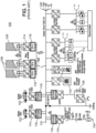
- FIG. 1 shows a typical direct current, or DC, electrical distribution network 100, which might be implemented in an office building or a residential building.
- a DC network 100 has one or more power sources, such as the batteries of electric vehicles 102, the public electrical grid 104, a storage battery 106, or photovoltaic panels 108.
- the DC network 100 also has a central power distribution bus 110 to distribute the power from the power sources 102, 104, 106, 108 to various loads 112.
- Each power source 102, 104, 106, 108 is connected to the central bus 110 via a power converter 114.
- Each power converter 114 converts the current delivered by the corresponding power source to match the voltage rating of the central bus 110.
- the power sources 102, 104, 106, 108 must be protected against overcurrent, which typically may be caused by overloads and short circuits in the DC network 100.
- a circuit breaker 116 is connected between each power source 102, 104, 106, 108 and the central bus 110, namely to the output of each power converter 114.
- circuit breakers 116 With their corresponding power converters 114. This would reduce the number of separate components of the DC network 100, make it more compact and the setup easier.
- the proposed circuit breaker should be easy to integrate into existing power converters.
- this object is achieved with a solid-state circuit breaker module for integration into a power converter, the circuit breaker module having an outer housing, the outer housing containing a semiconductor switch, which acts as a main overcurrent protection device, an electromechanical protective relay, which acts as a fallback overcurrent protection device, a fuse, which acts as an ultimate overcurrent protection device, a current sensor for detecting an overcurrent, a controller for tripping the semiconductor switch and the protective relay when the current sensor detects an overcurrent, and a sealed gas chamber filled with an arc-extinguishing gas, the gas chamber containing the semiconductor switch, the protective relay, and the fuse.
- the main, fallback and ultimate overcurrent protection device viz., the semiconductor switch, the protective relay and the fuse
- the circuit breaker becomes an integral part of the power converter.
- solid-state circuit breaker modules that will now be described in detail are self-contained electrical units, which are meant to be integrated into larger electrical devices.
- these solid-state circuit breaker modules can be integrated into power converters. More precisely, the output of a power converter may be protected against overcurrents by fitting a solid-state circuit breaker module of the present disclosure between the DC-link capacitor and the output terminals of the power converter.
- a solid-state circuit breaker module of the present disclosure may for example be mounted on the printed circuit board of the power converter that is to be protected.
- Solid-state circuit breaker modules as described herein, when used as protection devices in electrical distribution networks, will each be mounted next to the source that they protect.
- This distributed/decentralised protection architecture is advantageous in that it dispenses with the traditional central distribution cabinets housing many individual circuit breakers.
- a solid-state circuit breaker module of the present disclosure typically has an electrical circuit like the one shown in figure 2 .
- This electrical circuit 1 (delimited by a dashed rectangle) is a DC circuit with two inputs L+IN and L-IN, and two outputs L+OUT and L-OUT. It is a protection circuit, which protects a source 3 connected to its inputs L+IN and L-IN from overcurrents.
- the protection circuit 1 may provide bidirectional protection, i.e., may not only protect the source 3 from overcurrents, but also a load 5 connected to its outputs L+OUT and L-OUT. This will be explained in more detail further below.
- the protection circuit 1 includes a main overcurrent protection device, namely one or more semiconductor switches 7, a fallback overcurrent protection device, namely an electromechanical protective relay 9, a current sensor 11 for detecting an overcurrent, a current rise delaying/time- buyer inductor 13, and a controller 15 connected to the semiconductor switches 7, the current sensor 11 and the protective relay 9.
- a main overcurrent protection device namely one or more semiconductor switches 7, a fallback overcurrent protection device, namely an electromechanical protective relay 9, a current sensor 11 for detecting an overcurrent, a current rise delaying/time- buyer inductor 13, and a controller 15 connected to the semiconductor switches 7, the current sensor 11 and the protective relay 9.
- the main overcurrent protection device comprises two semiconductor switches 7.1 and 7.2.
- Each semiconductor switch 7.1 and 7.2 is implemented as a transistor, here an N-channel MOSFET in depletion mode. Other transistors or other semiconductor devices may alternatively be used.
- the first semiconductor switch 7.1 protects the source 3 from an overcurrent
- the second semiconductor switch 7.2 protects the load 5 from an overcurrent. Indeed, as apparent from figure 2 , the two transistors 7.1, 7.2 are connected in anti-series.
- the controller 15 can act on the gates of the transistors 7.1 and 7.2 to trip one, or the other, or both in the case of an overcurrent.
- the main overcurrent protection device may also have a single semiconductor switch 7.1 instead of two semiconductor switches.
- the single semiconductor switch 7.1 which, again, may preferably be a transistor, will then only protect the source 3 from an overcurrent but not the load 5.
- a diode 8 may be added in series with the single transistor 7.1 to ensure that power may only flow in one direction, from the source 3 to the load 5.
- the current sensor 11 is connected in series with the semiconductor switches 7.1 and 7.2.
- the current sensor 11 may be implemented as a resistor.
- the controller 15 monitors the voltage across the resistor 11, and thus the current flow.
- the protective relay 9 is connected downstream of and in series with the transistors 7.1 and 7.2 and the current sensing resistor 11.
- the controller 15 trips the protective relay 9 when the current sensor 11 detects an overcurrent, concurrently with the first and/or second transistors 7.1, 7.2.
- the time-buyer inductor 13 is connected in series between the protective relay 9 and the output L+OUT.
- the time-buyer inductor 13 delays the current rise in case of an overcurrent so that the current interrupting components, i.e., the semiconductor switches 7.1, 7.2 and, if applicable, the protective relay 9, have sufficient time to react and break the circuit.
- the solid-state circuit breaker module 17 shown in figures 3 to 5 is a self-contained device, which may be bought individually. It may be mounted on a printed circuit board together with other modules or electronic components.
- the solid-state circuit breaker module 17 contains the protection circuit 1 of Fig. 2 .
- the circuit breaker module 17 is delimited by an outer housing 19.
- a pair of input terminals 21.1 and 21.2 is arranged at one end of the outer housing 19.
- a pair of output terminals 23.1, 23.2 is arranged at the other end of the outer housing 19.
- a source 3 may be connected to the input terminals 21 and a load 5 to the output terminals 23 (cf. figure 3 ).
- the circuit breaker module 17 will interrupt the current flow from the source 3 to the load 5.
- the circuit breaker module 17 is arranged between the source 3 and the load 5 and may disconnect the load 5 from the source 3, e.g., in case of a short circuit or if the load 5 is overloading the source 3.
- the circuit breaker module 17 may comprise a cooling plate 22, which may be arranged at the bottom of the outer housing 19.
- the cooling plate 22 may be implemented as a metal substrate.
- the function of the cooling plate 22 is to absorb the heat generated by the protection circuit 1 during operation of the circuit breaker module 17.
- the circuit breaker module 17 is integrated into a larger device, such as a power converter, its cooling plate 22 may be brought into contact with a heat sink 24 of the larger device, cf. Fig. 5 . In such a configuration, the heat generated by the circuit breaker module 17 is dissipated by the larger device's heat sink 24.
- One may thus design the circuit breaker module 17 without any heat sink.
- the circuit breaker module 17 may also have an input-output connector 25 located on the outer housing 19.
- the input-output connector 25 includes a set of connecting pins 27.
- the input-output connector 25 is an interface to allow communication between the circuit breaker module's controller 15 and an external device, such as the microcontroller of the power converter into which the circuit breaker module 17 is integrated. An external device may thus be connected to the circuit breaker module 17 via the input-output connector 25.
- the pins 27 of the input-output connector 25 may be used for example to supply power to the circuit breaker module 17, to synchronise the voltage with that of the electrical grid to which the circuit breaker module 17 is connected, to indicate errors to the external device (overload, overcurrent, overvoltage, overtemperature), or to switch the circuit breaker module 17 on or off.
- a sealed gas chamber 29, filled with an arc-extinguishing gas, is located inside the outer housing 19.
- the sealed gas chamber 29 is identified in figure 2 by a dashed rectangle.
- the arc-extinguishing gas in the gas chamber 29 may be an inert gas, such as sulphur hexafluoride (SF 6 ).
- the gas chamber 29 contains the main components of the circuit breaker module 17 that are relevant to interrupting the current, in particular the one or more semiconductor switches 7 and the protective relay 9.
- the time-buyer inductor 13 is also arranged inside the single gas chamber 29.
- the circuit breaker module 17 becomes very compact.
- the resulting small size of the circuit breaker module 17 allows it to be easily integrated e.g., into a power converter.
- the controller 15 is located inside the outer housing 19 but outside of the sealed gas chamber 29. The controller 15 may sit on top of the sealed gas chamber 29.
- a rotatable key socket 31 is arranged on the outer housing 19.
- a hand key 33 (cf. figures 4 and 5 ) can be inserted into the rotatable socket 31. Turning the inserted hand key 33 results in rotation of the socket 31, which in turn resets the protective relay 9, when it has tripped.
- the sealed gas chamber 29 also contains a fuse 35, which acts as an ultimate overcurrent protection device.
- the fuse 35 will blow if, in case of an overcurrent, both the one or more semiconductor switches 7 and the protective relay 9 failed to break the circuit.
- the fuse 35 is implemented as a bond wire interconnecting the one or more semiconductor switches 7 and the protective relay 9.
- the bond wire 35 is designed to melt in the presence of a sustained overcurrent.
- An exemplary bond wire fuse 35 is shown in figure 7 .
- This particular bond wire 35 has a segment 37 with a reduced cross-section. If an overcurrent I flows through the bond wire fuse 35, the thinner segment 37 will heat excessively and melt. Consequently, the bond wire 35 will be cut in two and the current will cease flowing therethrough.
- the protective relay 9 comprises two spaced-apart fixed contacts 39.1 and 39.2, a displaceable contact 41, and a displacement device for displacing the displaceable contact 41.
- the present embodiment discloses two fixed contacts 39.1 and 39.2, it should be understood that the protective relay can comprise more than two fixed contacts, such as 2xn contacts with n being an integer greater than 1. Having more contacts allows to reduce the stroke of the displacement device with respect to the required dielectric insulation when the protective relay 9 is tripped.
- the function of the locking bolt 49 is to maintain the rotatable bar 43 in the wound-up position, and thus the protective relay 9 in the closed position. To maintain the rotatable bar 43 in the wound-up position, the locking bolt 49 is inserted into a complementary groove 51 of the rotatable bar 43.
- the protective relay 9 can be tripped by removing the locking bolt 49 from the groove 51 in the rotatable bar 43. Indeed, when the locking bolt 49 is removed from the groove 51, the rotatable bar 43 will rotate into the unwound position under the urge of the spiral spring 45, which in turn will bring the displaceable contact 41 into the open state.
- the insertion of the locking bolt 49 into the groove 51 and the removal therefrom is controlled by the electromagnetic coil 47.
- the electromagnetic coil 47 surrounds the locking bolt 49.
- the locking bolt 49 behaves like a plunger inside the electromagnetic coil 47.
- the electromagnetic coil 47 When the electromagnetic coil 47 is energised, it pushes the locking bolt 49 into the corresponding groove 51.
- the electromagnetic coil 47 is de-energised by the controller 15, the locking bolt 49 drops back into the coil 47, as indicated by arrow G in figure 6 .
- the controller 15 trips the protective relay 9 by de-energising the electromagnetic coil 47.
- the rotatable bar 43 of the just-described displacement device cooperates with a rotatable permanent magnet 53, such as a bar magnet, which is fitted to the rotatable key socket 31, cf. Fig. 5 .
- the permanent magnet 53 rotates in unison with the key socket 31. Hence, a twisting of the hand key 33 results in a corresponding rotation of the key socket 31 and the permanent magnet 53.
- the permanent magnet 53 is located close to the rotatable bar 43 of the protective relay 9.
- the permanent magnet 53 and the rotatable bar 43 are located on opposite sides of an upper wall 55 of the gas chamber 29. More precisely, the permanent magnet 53 is arranged in proximity to the gas chamber wall 55, outside of the gas chamber 29, and the rotatable bar 43 is also arranged in proximity to the gas chamber wall 55, but inside the gas chamber 29. In other words, the permanent magnet 53 and the rotatable bar 43 face each other while being separated by the gas chamber wall 55.
- the rotatable bar 43 comprises a ferromagnetic material. Accordingly, the rotatable bar 43 is susceptible to a magnetic force exerted by the permanent magnet 53 across the gas chamber wall 55.
- a contact sensor 44 is arranged inside the gas chamber 29, above the protective relay 9.
- the contact sensor 44 is adapted to detect the current state of the protective relay 9, i.e., whether the relay 9 is in the operational or tripped state.
- the contact sensor 44 may for example be a device that monitors the electric current drawn by the electromagnetic coil 47.
- Resetting the protective relay 9 is done in the following way: a user inserts the hand key 33 into the key socket 31 and turns the hand key 33. This results in a rotation of the key socket 31, which is followed by the permanent magnet 53. The rotation of the permanent magnet 53 magnetically induces, across the gas chamber wall 55, a rotation of the rotatable bar 43. The rotation of the rotatable bar 43 then moves the displaceable contact 41 into its closed state, against the urge of the spiral spring 45. This re-establishes an electrical connection between the two fixed contacts 39.1 and 39.2, and thus the protective relay 9 is reset.
- the just-described arrangement with an external permanent magnet 53 acting on a magnetic bar 43 inside the gas chamber 29 is particularly advantageous since it allows resetting the protective relay 9 from outside of the gas chamber 29 without compromising the tightness of the gas chamber 29. Thanks to this arrangement, the protective relay 9 can be located inside the sealed gas chamber 29 and still be controlled from the outside.
- FIGs. 8 and 9 show a second embodiment, which also has a protective relay 9 inside a sealed gas chamber 29 and a mechanism to reset the protective relay 9 from outside of the gas chamber 29, this mechanism maintaining the tightness of the gas chamber 29.
- the permanent magnet 53 and the magnetic bar 43 are replaced by an elastic sealing bellows 57.
- the gas chamber 29 is the delimited by a rigid enclosure 59 and the elastic sealing bellows 57, set into the rigid enclosure 59.
- the bellows 57 is in mechanical contact with the protective relay 9 to allow resetting of the protective relay 9 from outside of the gas chamber 29 by mechanical action on the bellows 57.
- Figure 8 shows the bellows 57 and the protective relay 9 in the normal operating state, where the protective relay 9 is closed.
- a mechanical latch (not illustrated) can be used instead of an electromagnetic coil 47 to retain the displaceable contact 41 in a closed state with the fixed contacts 39, thus allowing reducing electromagnetic power consumption.
- Figure 9 shows the bellows 57 and the protective relay 9 in a tripped state, where the protective relay 9 is open.
- the spiral spring 45 urges the displaceable contact 41 away from the fixed contacts 39.
- the stiffness of the spiral spring 45 can be designed to find a trade-off between a sufficient opening speed to move from the normal operating state to the tripped state, and a reduced power consumption of electromagnetic coil 47.
- a mechanical action can be applied on the displaceable contact 41 from outside of the sealed gas chamber 29.
- the displaceable contact 41 remains in the normal operating state as the bellows 57 and the electromagnetic coil 47 (or mechanical latch) exert a cumulative force that is greater than the one from the spiral spring 45 on the displaceable contact 41.
- the module 17 can include a mechanical position indicator to know the state of the protective relay 9.
- This indicator may be the bellows 57, which may be directly visible through the enclosure 59. This arrangement thus allows to directly and mechanically reflect the state of the displaceable contact 41 by the position of the bottom of the bellows 57.
Landscapes
- Physics & Mathematics (AREA)
- Electromagnetism (AREA)
- Engineering & Computer Science (AREA)
- Power Engineering (AREA)
- Emergency Protection Circuit Devices (AREA)
- Protection Of Static Devices (AREA)
- Power Conversion In General (AREA)
Priority Applications (4)
| Application Number | Priority Date | Filing Date | Title |
|---|---|---|---|
| EP23305382.6A EP4435818A1 (de) | 2023-03-21 | 2023-03-21 | Halbleiterschaltermodul zur integration in einen leistungswandler |
| CN202480020134.1A CN120826756A (zh) | 2023-03-21 | 2024-03-07 | 用于集成到电力转换器中的固态断路器模块 |
| PCT/EP2024/056034 WO2024194033A1 (en) | 2023-03-21 | 2024-03-07 | A solid-state circuit breaker module for integration into a power converter |
| TW113109966A TW202445939A (zh) | 2023-03-21 | 2024-03-18 | 用於整合到電源轉換器中的固態斷路器模組 |
Applications Claiming Priority (1)
| Application Number | Priority Date | Filing Date | Title |
|---|---|---|---|
| EP23305382.6A EP4435818A1 (de) | 2023-03-21 | 2023-03-21 | Halbleiterschaltermodul zur integration in einen leistungswandler |
Publications (1)
| Publication Number | Publication Date |
|---|---|
| EP4435818A1 true EP4435818A1 (de) | 2024-09-25 |
Family
ID=85792635
Family Applications (1)
| Application Number | Title | Priority Date | Filing Date |
|---|---|---|---|
| EP23305382.6A Pending EP4435818A1 (de) | 2023-03-21 | 2023-03-21 | Halbleiterschaltermodul zur integration in einen leistungswandler |
Country Status (4)
| Country | Link |
|---|---|
| EP (1) | EP4435818A1 (de) |
| CN (1) | CN120826756A (de) |
| TW (1) | TW202445939A (de) |
| WO (1) | WO2024194033A1 (de) |
Families Citing this family (1)
| Publication number | Priority date | Publication date | Assignee | Title |
|---|---|---|---|---|
| CN120954949B (zh) * | 2025-10-16 | 2026-01-23 | 浙江中贝能源科技有限公司 | 单激励源的主被动一体保护智能熔断器 |
Citations (3)
| Publication number | Priority date | Publication date | Assignee | Title |
|---|---|---|---|---|
| US20080143462A1 (en) * | 2006-12-14 | 2008-06-19 | Hamilton Sundstrand Corporation | High voltage DC contactor hybrid without a DC arc break |
| EP2234136A1 (de) * | 2007-12-28 | 2010-09-29 | Panasonic Electric Works Co., Ltd | Gleichstromschalter |
| US20210057904A1 (en) * | 2019-08-20 | 2021-02-25 | Hyundai Motor Company | Apparatus for protecting device of motor drive inverter |
-
2023
- 2023-03-21 EP EP23305382.6A patent/EP4435818A1/de active Pending
-
2024
- 2024-03-07 WO PCT/EP2024/056034 patent/WO2024194033A1/en not_active Ceased
- 2024-03-07 CN CN202480020134.1A patent/CN120826756A/zh active Pending
- 2024-03-18 TW TW113109966A patent/TW202445939A/zh unknown
Patent Citations (3)
| Publication number | Priority date | Publication date | Assignee | Title |
|---|---|---|---|---|
| US20080143462A1 (en) * | 2006-12-14 | 2008-06-19 | Hamilton Sundstrand Corporation | High voltage DC contactor hybrid without a DC arc break |
| EP2234136A1 (de) * | 2007-12-28 | 2010-09-29 | Panasonic Electric Works Co., Ltd | Gleichstromschalter |
| US20210057904A1 (en) * | 2019-08-20 | 2021-02-25 | Hyundai Motor Company | Apparatus for protecting device of motor drive inverter |
Also Published As
| Publication number | Publication date |
|---|---|
| TW202445939A (zh) | 2024-11-16 |
| WO2024194033A1 (en) | 2024-09-26 |
| CN120826756A (zh) | 2025-10-21 |
Similar Documents
| Publication | Publication Date | Title |
|---|---|---|
| US8213133B2 (en) | Load breaker arrangement | |
| US20240274389A1 (en) | Electrical protection devices and systems | |
| JP2023511939A (ja) | 固体回路遮断器 | |
| WO2015077203A1 (en) | Circuit breaker assembly including a plurality of controllable circuit breakers for local and/or remote control | |
| CN117321717A (zh) | 具有集成切断模块的电气保护设备和系统 | |
| CN103329237B (zh) | 提供跳闸单元外部的区域选择性联锁接口的附件模块以及包括该附件模块的系统和电路断续器 | |
| EP4435818A1 (de) | Halbleiterschaltermodul zur integration in einen leistungswandler | |
| EP2132761B1 (de) | Reststromeinrichtung | |
| EP1399940A1 (de) | Miniatur-leistungsschalterpol | |
| EP4176501B1 (de) | Lastzentrum zur reduzierung der auslösezeit bei kurzschlussfehlern | |
| US11955954B2 (en) | Semiconductor circuit breaker | |
| Chandran et al. | Design considerations for relay and circuit breaker | |
| US20240112873A1 (en) | Insulating-material housing and compact circuit breaker | |
| CN118830044A (zh) | 电子开关轨道式设备和绝缘材料壳体 | |
| CN116435149A (zh) | 低压保护开关设备和组装方法 | |
| US20250246389A1 (en) | High current disconnect module | |
| US20250182992A1 (en) | Modular electrical protection device with control and power modules | |
| EP4607554A1 (de) | Hochstromtrennmodul | |
| SU1304127A1 (ru) | Устройство дл дистанционного отключени выключател | |
| CN116435121A (zh) | 单极壳体模块和低压保护开关设备 | |
| US11538649B2 (en) | Circuit breaker housing | |
| Wafer | The impact of solid-state technology on molded case circuit breakers | |
| SU760230A1 (ru) | Автоматический выключатель1 | |
| KR200377582Y1 (ko) | 전력용 기기의 차단 제어회로 장치 | |
| KR200146435Y1 (ko) | 차단기 |
Legal Events
| Date | Code | Title | Description |
|---|---|---|---|
| PUAI | Public reference made under article 153(3) epc to a published international application that has entered the european phase |
Free format text: ORIGINAL CODE: 0009012 |
|
| STAA | Information on the status of an ep patent application or granted ep patent |
Free format text: STATUS: THE APPLICATION HAS BEEN PUBLISHED |
|
| AK | Designated contracting states |
Kind code of ref document: A1 Designated state(s): AL AT BE BG CH CY CZ DE DK EE ES FI FR GB GR HR HU IE IS IT LI LT LU LV MC ME MK MT NL NO PL PT RO RS SE SI SK SM TR |
|
| STAA | Information on the status of an ep patent application or granted ep patent |
Free format text: STATUS: REQUEST FOR EXAMINATION WAS MADE |
|
| 17P | Request for examination filed |
Effective date: 20241007 |
|
| RBV | Designated contracting states (corrected) |
Designated state(s): AL AT BE BG CH CY CZ DE DK EE ES FI FR GB GR HR HU IE IS IT LI LT LU LV MC ME MK MT NL NO PL PT RO RS SE SI SK SM TR |
|
| GRAP | Despatch of communication of intention to grant a patent |
Free format text: ORIGINAL CODE: EPIDOSNIGR1 |
|
| STAA | Information on the status of an ep patent application or granted ep patent |
Free format text: STATUS: GRANT OF PATENT IS INTENDED |
|
| INTG | Intention to grant announced |
Effective date: 20251110 |