EP4435375A1 - Interferometervorrichtung - Google Patents
Interferometervorrichtung Download PDFInfo
- Publication number
- EP4435375A1 EP4435375A1 EP24164048.1A EP24164048A EP4435375A1 EP 4435375 A1 EP4435375 A1 EP 4435375A1 EP 24164048 A EP24164048 A EP 24164048A EP 4435375 A1 EP4435375 A1 EP 4435375A1
- Authority
- EP
- European Patent Office
- Prior art keywords
- birefringent
- adjustable
- optical
- birefringent component
- compensation
- Prior art date
- Legal status (The legal status is an assumption and is not a legal conclusion. Google has not performed a legal analysis and makes no representation as to the accuracy of the status listed.)
- Pending
Links
Images





Classifications
-
- G—PHYSICS
- G01—MEASURING; TESTING
- G01B—MEASURING LENGTH, THICKNESS OR SIMILAR LINEAR DIMENSIONS; MEASURING ANGLES; MEASURING AREAS; MEASURING IRREGULARITIES OF SURFACES OR CONTOURS
- G01B9/00—Measuring instruments characterised by the use of optical techniques
- G01B9/02—Interferometers
- G01B9/02097—Self-interferometers
-
- G—PHYSICS
- G01—MEASURING; TESTING
- G01B—MEASURING LENGTH, THICKNESS OR SIMILAR LINEAR DIMENSIONS; MEASURING ANGLES; MEASURING AREAS; MEASURING IRREGULARITIES OF SURFACES OR CONTOURS
- G01B9/00—Measuring instruments characterised by the use of optical techniques
- G01B9/02—Interferometers
- G01B9/02001—Interferometers characterised by controlling or generating intrinsic radiation properties
- G01B9/02011—Interferometers characterised by controlling or generating intrinsic radiation properties using temporal polarization variation
-
- G—PHYSICS
- G01—MEASURING; TESTING
- G01B—MEASURING LENGTH, THICKNESS OR SIMILAR LINEAR DIMENSIONS; MEASURING ANGLES; MEASURING AREAS; MEASURING IRREGULARITIES OF SURFACES OR CONTOURS
- G01B9/00—Measuring instruments characterised by the use of optical techniques
- G01B9/02—Interferometers
-
- G—PHYSICS
- G01—MEASURING; TESTING
- G01B—MEASURING LENGTH, THICKNESS OR SIMILAR LINEAR DIMENSIONS; MEASURING ANGLES; MEASURING AREAS; MEASURING IRREGULARITIES OF SURFACES OR CONTOURS
- G01B9/00—Measuring instruments characterised by the use of optical techniques
- G01B9/02—Interferometers
- G01B9/02055—Reduction or prevention of errors; Testing; Calibration
- G01B9/02056—Passive reduction of errors
- G01B9/02061—Reduction or prevention of effects of tilts or misalignment
-
- G—PHYSICS
- G01—MEASURING; TESTING
- G01B—MEASURING LENGTH, THICKNESS OR SIMILAR LINEAR DIMENSIONS; MEASURING ANGLES; MEASURING AREAS; MEASURING IRREGULARITIES OF SURFACES OR CONTOURS
- G01B9/00—Measuring instruments characterised by the use of optical techniques
- G01B9/02—Interferometers
- G01B9/02055—Reduction or prevention of errors; Testing; Calibration
- G01B9/02056—Passive reduction of errors
- G01B9/02058—Passive reduction of errors by particular optical compensation or alignment elements, e.g. dispersion compensation
-
- G—PHYSICS
- G01—MEASURING; TESTING
- G01J—MEASUREMENT OF INTENSITY, VELOCITY, SPECTRAL CONTENT, POLARISATION, PHASE OR PULSE CHARACTERISTICS OF INFRARED, VISIBLE OR ULTRAVIOLET LIGHT; COLORIMETRY; RADIATION PYROMETRY
- G01J3/00—Spectrometry; Spectrophotometry; Monochromators; Measuring colours
- G01J3/28—Investigating the spectrum
- G01J3/45—Interferometric spectrometry
-
- G—PHYSICS
- G01—MEASURING; TESTING
- G01N—INVESTIGATING OR ANALYSING MATERIALS BY DETERMINING THEIR CHEMICAL OR PHYSICAL PROPERTIES
- G01N21/00—Investigating or analysing materials by the use of optical means, i.e. using sub-millimetre waves, infrared, visible or ultraviolet light
- G01N21/62—Systems in which the material investigated is excited whereby it emits light or causes a change in wavelength of the incident light
- G01N21/63—Systems in which the material investigated is excited whereby it emits light or causes a change in wavelength of the incident light optically excited
- G01N21/64—Fluorescence; Phosphorescence
- G01N2021/6417—Spectrofluorimetric devices
- G01N2021/6421—Measuring at two or more wavelengths
-
- G—PHYSICS
- G01—MEASURING; TESTING
- G01N—INVESTIGATING OR ANALYSING MATERIALS BY DETERMINING THEIR CHEMICAL OR PHYSICAL PROPERTIES
- G01N21/00—Investigating or analysing materials by the use of optical means, i.e. using sub-millimetre waves, infrared, visible or ultraviolet light
- G01N21/62—Systems in which the material investigated is excited whereby it emits light or causes a change in wavelength of the incident light
- G01N21/63—Systems in which the material investigated is excited whereby it emits light or causes a change in wavelength of the incident light optically excited
- G01N21/64—Fluorescence; Phosphorescence
- G01N21/6445—Measuring fluorescence polarisation
-
- G—PHYSICS
- G01—MEASURING; TESTING
- G01N—INVESTIGATING OR ANALYSING MATERIALS BY DETERMINING THEIR CHEMICAL OR PHYSICAL PROPERTIES
- G01N21/00—Investigating or analysing materials by the use of optical means, i.e. using sub-millimetre waves, infrared, visible or ultraviolet light
- G01N21/62—Systems in which the material investigated is excited whereby it emits light or causes a change in wavelength of the incident light
- G01N21/63—Systems in which the material investigated is excited whereby it emits light or causes a change in wavelength of the incident light optically excited
- G01N21/64—Fluorescence; Phosphorescence
- G01N21/645—Specially adapted constructive features of fluorimeters
- G01N21/6456—Spatial resolved fluorescence measurements; Imaging
Definitions
- the present invention relates to an interferometer apparatus.
- Interferometers are widely used both in academia and industry for a great variety of applications. They can be used to measure the spectral component of the light, measure the speed of light, evaluate imperfections of transparent materials such as optical elements, measure lengths and more.
- Michelson's interferometers and their variations are the most used.
- two replicas are created employing a beam splitter, and they travel along different paths.
- the path travelled by one of the two replicas can be varied and the two are then recombined into one output beam making interference possible.
- the two replicas travel along two distinct paths, they can experience different perturbations and this can negatively affect the quality of the interference.
- the two replicas travel along the same path and experience the same perturbations, so they are phase locked. This assures great delay stability and interference quality and these devices can work well even with shorter wavelengths down to the visible and ultraviolet range. Moreover, these devices are compact and robust and can be applied also in industrial environments and under harsh conditions.
- a modified version of a Babinet-Soleil compensator interferometer is described in document US20213/329228 adding other birefringent elements to compensate for the group velocity dispersion and to lock the propagation delay of one of the two polarizations, useful for pump-probe spectroscopy.
- the Applicant has noticed that the Babinet-Soleil based interferometers of the above cited documents are very sensitive to the light travelling direction inside the interferometer.
- This light direction sensitivity is because the birefringence of the used material and the path length inside the crystals is angle-dependent and since such interferometers use two birefringent optical crystals (the second one to permit also negative delays) the dependency is even worsened.
- the light cannot be collimated and consists of beams travelling having a multitude of angular directions.
- the interfering output beam shows several spatial fringes alternating high and low intensity for constructive and destructive interference, respectively.
- the Applicant observes that these fringes are present because the light propagates inside the interferometer with different angular directions and the interferometer delay depends strongly depends on them. So, for certain directions, there is a constructive interference condition and the intensity is high while in others there is destructive interference and the intensity is low.
- a single pixel detector spatially integrates the intensity profiles of the output beam and this decreases the interference contrast.
- the beam size must be reduced by using a small aperture selecting only the portion of the output beam corresponding to a single fringe.
- the angle dependency of the optical delay is particularly problematic in using the common-path interferometer in imaging such as for spectral imaging or microscopy as described in document US11346719 .
- an imaging lens which collects the light coming from each point of a large scene of interest.
- Each ray bundle coming from a specific point comprises a collection of rays propagating with different angles inside the interferometer. This is especially accentuated in imaging closer objects since, for each point of the scene, the range of angles of the collected rays by the lens is bigger.
- FIG. 12 Another example of a scanning common path interferometer is shown in publication " Birefringent Fourier-transform imaging spectrometer", Vol. 12, Issue 22, pp. 5368-5374 (2004) by A. R Harvey et Al.
- the interferometer is based on two Wollaston prisms placed in between two polarizers. The first prism separates angularly the replicas and the second one is used to make the two beams collinear again but separated by a distance that depends on the distance between the two Wollaston prisms. A lens is used to recombine spatially the beams and let them interfere with a detector. The second prism is scanned across the beam and due to its configuration, this introduces an optical path difference between the two replicas.
- the two light replicas interfere at the detector coming from different directions; therefore, also the wavefront of the two beams are inclined accordingly and this causes a loss of the interferometric modulation at the detector that reduces the signal-to-background ratio.
- the Wollaston prisms separate angularly the different spectral components of the light and this further reduces the interferometric modulation at the detector, because the same colour of the two orthogonally polarized replicas impinges on a slightly different position of the camera, thus reducing the interferometric signal.
- this known interferometer introduces strongly angular dependent delays and this limits the performance of the system for non-point like sources. It is important to note that these two problems increase when the two Wollaston prisms are made bigger in order to increase the maximum interferometric delay and therefore the maximum resolution.
- the present invention addresses the problem of providing an interferometer apparatus, of the type comprising an adjustable birefringent device producing replicas with orthogonal polarizations, in which the radiation direction dependency is eliminated or reduced so increasing the interference quality and, as an example, obtaining an apparatus that effectively work for single-point radiation sources as well as extended radiation sources.
- the present invention relates to an interferometer apparatus as defined by the appended claim 1. Particular embodiments of the apparatus are described by the dependent claims 2-14.
- Figure 1 shows a first embodiment of an interferometer apparatus 100 which can be employed for example as a spectrometer, for measuring the photoluminescence of sample, as fluorimeter.
- the interferometer apparatus 100 can be applied for spectral images of samples in microscopy and macroscopy.
- the interferometer apparatus 100 comprises a first adjustable birefringent device 110 and a first compensation optical device 120, which is optically coupled with the first adjustable birefringent device 110.
- the interferometer apparatus 100 comprises a source module 130 which can be an electromagnetic radiation source or an optical imaging system.
- the source module 130 is an electromagnetic radiation source, it is configured to generate a radiation (also called "light", without limitation to visible light wavelengths) propagating along the first adjustable birefringent device 110 and the first compensation optical device 120.
- the electromagnetic radiation source 130 can be a coherent source (e.g. a laser) or an incoherent source (e.g. a lamp).
- the electromagnetic radiation source 130 can generate polychromatic radiation or monochromatic radiation of either linear or other types of polarizations.
- the source module 130 can be even a sample emitting, reflecting or scattering light.
- an optical imaging system is added in front and/or after the interferometer apparatus 100 and the image of the sample is formed on a bi-dimensional detector.
- the interferometer apparatus 100 can be configured to operate in one of the wavelength ranges selected from: 180-3500 nm, 500-5000 nm, 400-20000 nm.
- a radiation R comprising a bundle of rays, emerges from the source module 130.
- the radiation IN R defines a main propagation direction ⁇ .
- the first adjustable birefringent device 110 is configured to receive an input radiation IN R and produce corresponding replicas having reciprocally orthogonal polarizations. Such replicas are delayed from each other by an adjustable time delay depending on a configuration assumed by the first adjustable birefringent device 110.
- the first adjustable birefringent device 110 introduces an additional time delay between said replicas.
- the first adjustable birefringent device 110 is provided with an adjustable wedge pair BL1 and an optical element BL2.
- the adjustable wedge pair BL1 is configured to provide an adjustable time delay between radiation components passing through it and having reciprocally orthogonal polarizations.
- the adjustable wedge pair BL1 comprises a first optical wedge 101 and a second optical wedge 102.
- Both first 101 and second 102 optical wedges are made of a birefringent material.
- the first 101 and second 102 optical wedges have corresponding optical axis o 1 of the birefringence material parallel to each other.
- the first optical wedge 101 and the second optical wedge 102 are optical prisms, having, preferably, the same apex angle.
- the first optical wedge 101 coupled to the second optical wedge 102 is equivalent to an optical plate having variable thickness.
- At least one of the two optical wedges 101 and 102 is movable (e.g. it can be translated) along a direction transversal to the main direction ⁇ by means of an actuator 104, schematically represented in figure 1 .
- the first optical wedge 101 is movable and the second optical wedge 102 is fixed.
- the adjustable time delay introduced by the adjustable wedge pair BL1 is dependent on the variable position of the first optical wedge 101.
- the actuator 104 may be connected to a computer-controlled precision translation stage.
- first 101 and the second optical wedges 102 can be arranged to be very close to each other in order to reduce chromatic dispersion and spatial separation of the replicas.
- first optical wedge 101 and the second optical wedge 102 can be at a distance between the corresponding adjacent tilted faces of 0-1 mm.
- optical element BL2 is a birefringent plate (e.g. with fixed thickness) having a respective optical axis o2 of the birefringent material perpendicular to the optical axis o1 of adjustable wedge pair BL1 and the main direction ⁇ .
- the optical element BL2 is coupled with the adjustable wedge pair BL1 and, according to the considered example, is configured to introduce a fixed phase delay between the radiations having reciprocally orthogonal polarizations.
- the adjustable wedge pair BL1 (i.e. first optical wedge 101 and second optical wedge 102) is made by a birefringence material having a first ordinary index n o and a first extraordinary index n e and has an adjustable thickness t1v.
- t1 one specific value that the variable thickness tlv can assume during the movement of the first optical wedge 101 is considered.
- the optical element BL2 is a plate having a thickness t2 equal to the specific thickness t1 of the adjustable wedge pair BL1 and is made by a birefringence material having the same first ordinary index n o and first extraordinary index n e defined for the adjustable wedge pair BL1.
- the adjustable wedge pair BL1 and the optical element BL2 are made by the same material such as an example: ⁇ -BBO.
- a first birefringence range ⁇ n can be defined as the difference n e - n o , that can have a positive or a negative sign.
- the first compensation optical device 120 is optically coupled to said first adjustable birefringent device 110 and configured to have a respective structural thickness and respective ordinary and extraordinary refractive indexes so as to introduce a compensation time delay between said replicas having a sign opposite to a sign of the additional time delay, so as to reduce the dependence on said angle of incidence in said interferometer apparatus.
- the first compensation optical device 120 comprises a polarization flipper 121, a first compensation birefringent plate BL3 and a second compensation birefringent plate BL4.
- the polarization flipper 121 is an optical device that converts the vertical polarization to a horizontal polarization and vice-versa.
- the polarization flipper 121 can be made with a half-wave plate at 45° or with a Fresnel romb. According to the shown example, an input port of the polarization flipper 121 optically coupled with an output of the optical element BL2.
- the first compensation birefringent plate BL3 has an input port optically coupled to an output port of the polarizing flipper 121 and second compensation birefringent plate BL4 has an input port optically coupled to an output port of the first compensation birefringent plate BL.
- the first compensation birefringent plate BL3 is designed to compensate for the angular dependence introduced by optical element BL2 and the second compensation birefringent plate BL4 is designed to compensate for the angular dependence introduced by the adjustable wedge pair BL1.
- the first compensation birefringent plate BL3 and the second compensation birefringent plate BL4 are designed so as to satisfy the following conditions:
- a condition more general than the conditions E) and F) is that the interferometer apparatus 100 of figure 1 is operated such as that the sum of the thickness tlv and t2 assumes a value equal to the sum of the thicknesses t3 and t4, for a specific operative configuration: i.e. when the thickness tlv assumes the specific value t1.
- the interferometer apparatus 100 is further equipped with an input polarizer 105 (particularly, placed between the source module 130 and the first adjustable birefringent device 110) to provide an output radiation of linear polarization transversal to the optical axes o1 and o2 of the first adjustable birefringent device 110 and, preferably, having tilt of 45° with respect to such axes.
- an input polarizer 105 particularly, placed between the source module 130 and the first adjustable birefringent device 110 to provide an output radiation of linear polarization transversal to the optical axes o1 and o2 of the first adjustable birefringent device 110 and, preferably, having tilt of 45° with respect to such axes.
- the interferometer apparatus 100 also includes an output polarizer 106 placed, as an example, at the output of the second compensation birefringent plate BL4 and designed to project the two replicas into a common polarization state so as they can interfere.
- an output polarizer 106 placed, as an example, at the output of the second compensation birefringent plate BL4 and designed to project the two replicas into a common polarization state so as they can interfere.
- the interferometer apparatus 100 can be equipped with a detector 107 and an analysis device 108.
- the detector 107 receive the radiation exiting the output polarizer 106 and convert such interfering radiation into an electrical signal that is provided to the analysis device 108 that performs elaborations depending on the particular application.
- the order of the elements of the interferometer apparatus 00 can be different from the one shown in the drawings.
- some of the above described components may be glued together.
- the first adjustable birefringent device 110 and the first compensation optical device 120 may be inserted into an interferometer apparatus different from the one depicted in figure 1 .
- the radiation R produced by the source module 130 passes through the input polarizer 105.
- the adjustable wedge pair BL1 introduces a time delay between the two orthogonally polarized components of the light oriented along the ordinary and the extraordinary axes of the birefringent material.
- the optical element BL2 introduces a fixed time delay between the two orthogonally polarized components of the radiation having a sign opposite to the one introduced by the adjustable wedge pair BL1.
- the combination of the adjustable wedge pair BL1 and the optical element BL2 allows setting time delays ranging from positive to negative values.
- the delay introduced by the first adjustable birefringent device 110 is different for each propagation angle and the delay also depends both on an azimuthal and polar angles of the radiation that enters the first adjustable birefringent device 110, as will further described later.
- the polarizations of the two replicas (i.e. the two orthogonally polarized components) exiting the first adjustable birefringent device 110 are exchanged by the polarization flipper 121.
- the corresponding components exit the first adjustable birefringent device 110 and pass through the compensation optical device 120.
- the first compensation birefringent plate BL3 acts on the radiation passing through it by at least partially compensating the time delay amount due to the angular dependence introduced by the optical element BL2.
- the second compensation birefringent plate BL4 acts on the radiation passing through it by at least partially compensating the time delay amount due to the angular dependence introduced by the adjustable wedge pair BL1.
- the compensation is due to the selection of the birefringence index values and the thickness for the plates BL3 and BL4 with respect that of the first adjustable birefringent device 110.
- the compensated radiation which is under the form of two replicas, exits the first compensation optical device 120 and reaches the output polarizer 106 that projects the two replicas into a common polarization state to cause interference.
- the interfering replicas are converted into a corresponding electrical signal by the detector 107 and said electrical signal is analyzed by the analysis device 108.It is noticed that the reduction or elimination of the angular dependence from the interfering replicas significantly improves the quality of the obtained interference positively affecting the subsequent analysis of the corresponding electrical signal especially for big detector areas and/or large emitting sources.
- the birefringent materials employable for the components of the interferometer apparatus 100 are, as an example, selectable from the following group: barium borate (BaB 2 O 4 ), alpha-barium borate ( ⁇ -BaB 2 O 4 ), lithium niobate (LiNbO 3 ), Calomel (Hg 2 Cl 2 ), beryl (Be 3 Al 2 (SiO 3 ) 6 ), calcite (CaCO 3 ), magnesium fluoride (MgF 2 ), quartz (SiO 2 ), ruby (Al 2 O 3 ), rutile (TiCt), sapphire (Al 2 O 3 ), silicon carbide(SiC), tourmaline (complex silicate), high zircon (ZrSiO 4 ), low zircon.
- barium borate BaB 2 O 4
- alpha-barium borate ⁇ -BaB 2 O 4
- lithium niobate LiNbO 3
- Calomel Hg 2 Cl 2
- the interferometer apparatus 100 of figure 1 perfectly compensates the angular dependence only at a very specific time delay, i.e. for a single position (i.e. the specific value t1) assumed by the first optical wedge 101.
- This compensating effect is reduced while scanning the interferometer to change the effective delay between the two replicas.
- scanning the first optical wedge 101 of figure 1 it is increased the thickness of this component and so its effect on the angular dependency of the interferometer apparatus 100. This can be a problem for very large delays in which there can be an overcompensation or undercompensation.
- the propagation of the ordinary ray is simply described by n o as if there were no birefringence involved.
- the extraordinary ray propagates differently from any wave in an isotropic optical material.
- This beam has an effective refractive index which has a value in between n o and n e .
- Its power flow is not in the same direction as the wave vector which is called also wave normal.
- the power flow does not respect Snell's law and behaves extraordinarily the direction of the wave vector follows it.
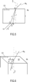
- figure 5 schematically shows (by a two-dimensionally representation) the propagation for a ray of radiation INr incident onto a crystal element BL (such as a plate having a thickness t) and forming an angle i with the main propagation direction ⁇ , which is perpendicular to the optical axis o1.
- a crystal element BL such as a plate having a thickness t
- the light is split into two rays with different angles: a first ray r and a second r .
- Figure 1 is a three-dimensional scheme of the used propagation model that allows showing the following:
- the angle ⁇ is the angle between the optical axis direction ô and the extraordinary ray wavevector (i.e. the second ray r ).
- n ⁇ 2 sin ⁇ 2 n e 2 + cos ⁇ 2 n o 2
- ⁇ P t 1 + 1 n e 2 ⁇ 1 n o 2 cos ⁇ 2 sin i 2 ⁇ 1 n e 2 sin i 2 1 n e 2 ⁇ n o 1 ⁇ sin i 2 n o 2
- the above equation (1.11) can be used to design the adjustable wedge pair BL1 since the gap in between the two wedges 101 and 102 can be made by design very small, as an example from 0 to 1 mm; 0 - 0,6 mm . Therefore its role in term of the path difference between the extraordinary and ordinary waves is just an offset with no contribution to the angular dependency and can be neglected.
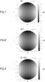
- This optical path difference ⁇ P h-v is displayed, for an exemplary case, as a function of ⁇ and i in figure 7 which is a polar map: the distance from the center of the map is the angle of incidence i ; ⁇ is the angle with respect to the x axis of the map.
- the angles i and ⁇ are expressed in radiant and the optical path difference ⁇ P h-v is expressed in meters.
- the optical element BL2 has the optical axis o2 rotated by 90 degrees with respect to optical axis o1.
- This optical path difference is displayed in figure 8 as a function of ⁇ and i, in a manner analogous to the previous figures.
- the total amount of the path difference (corresponding to an undesired addition time delay between the two replicas) is given by the sum of the amount of equation (1.12) and the amount of equation (1.13).
- the obtained interference at a particular wavelength has the fringe pattern shown in figure 10 (Interf.)
- the map of figure 10 shows the intensity (Intens.) of the beam after the progation into the adjustable birefringent device 110. This map is computed for ⁇ - BBO crystal and 400 nm radiation.
- the map is polar: the distance from the center of the map is the angle of incidence i ; ⁇ is the angle with respect to the x axis.
- the fringe pattern like that of figure 10 , is deleterious.
- the pattern like the one of figure 10 decreases the contrast, while using a common path interferometer in imaging mode because the light coming from a single point in the scene traverses the interferometer with many different propagating angles and the resulting interference signal as detected by a pixel of a 2D sensor will reduce the contrast.
- the first compensation optical device 120 has an opposite effect with respect to that of the first adjustable birefringent device 110.
- the first compensation optical device 120 is provided with the polarization flipper 121 (to swap the vertical with the horizontal polarization) and the first and second compensation birefringent plates BL3 and BL4, which are two plates with equal thickness with respect to the adjustable wedge pair BL1 and the optical element BL2.
- the first and the second compensation birefringent plates BL3 and BL4 have the same thickness in order to not vary the optical path difference between the two replicas, hence polarizations.
- the vertical polarization becomes horizontal and vice-versa.
- optical path difference considered in the following computing is the path difference between the originally horizontal and vertical polarizations, as indicated before.
- This optical path difference is displayed as a function of ⁇ and i in figure 11 .
- the originally horizontal polarization is still oriented along the vertical axis (i.e. perpendicularly to the plane of figure 1 ) and is the ordinary beam "o".
- the originally vertical polarization is still oriented along the horizontal (parallel to the plane of figure 1 ) and is the extraordinary beam "e", considering the direction of the optical axis o4.
- This optical path difference is displayed as a function of ⁇ and i in figure 12 .
- the total path difference introduced by the first compensation birefringent plate BL3 and the compensation birefringent plate BL4, after the polarization flipper 121, is given by the sum of the amount expressed by equations (1.14) and (1.15).
- An example, of said delay is shown figure 13 .
- first compensation birefringent plate BL3 and the compensation birefringent plate BL4 causes a path difference with the same magnitude and with an opposite sign as the one generated by first adjustable birefringent device 110, so as to reduce or eliminate the angular dependence.
- the total effect of the first adjustable birefringent device 110 and the first compensation optical device 120 is given by the sum of the amount expressed by the equations (1.12), (1.13), (1.14) and (1.15). This total effect is shown, as an example, in figure 14 where a uniform field can be appreciated.
- FIG 15 The corresponding interference signal across the field is shown in figure 15 .
- This map shows the intensity of the beam after the progation into the the interferometer apparatus 100. This map is computed for ⁇ - BBO crystal and 400 nm radiation. Since the optical path difference is the same for each inciding angle i and ⁇ , so the intensity value is constant.
- Figure 2 refers to a second embodiment of the interferometer apparatus 100 and shows a second adjustable birefringent device 140 (alternative to the one 110 of figure), optically coupled to the first compensation optical device 120.
- the second adjustable birefringent device 140 comprises the adjustable wedge pair BL1 identical or analogous to the one of figure 1 (having the first adjustable thickness tlv). In figure 2 , the positions of the first optical wedge 101 and the second optical wedge 102 have been inverted with respect to figure 1 .
- optical element BL2 of figure 2 is not a single plate but it comprises two optical wedges, where one of the wedges is movable, thus forming another adjustable wedge pair.
- optical element BL2 of figure 2 (having an adjustable second thickness t2v) comprises a third optical wedge 111 (movable) and a fourth optical wedge 112 (fixed).
- the third optical wedge 111 is movable synchronously with the first optical wedge 101 of the adjustable wedge pair BL1.
- the interferometer apparatus 100 of figure 1 perfectly compensates the angular dependence only at a very specific time delay, i.e. for a single position (i.e. the specific value t1) assumed by the first optical wedge 101
- the second embodiment described with reference to figure 2 allows compensating the angular dependence for each delay of the interferometer apparatus 100, namely, for each variable width of the second adjustable birefringent device 140.
- the polar map of figure 17 shows the intensity of the beam after the progation completely into the interferometery appartus 100 including the embodiment of figure 2 . This map is computed for a ⁇ -BBO crystal and 400 nm radiation.
- the configuration of the second embodiment ( figure 2 ) has a very high contrast not only for single-point light sources but also for large sources and in imaging mode as the change, in contrast, is very limited. Moreover, this advantage is retained for every delay of the interferometer.
- the interferometer apparatus 100 is operated so as the sum of the adjustable thicknesses tlv and t2v is maintained equal to the sum of the above defined thicknesses t3 and t4 of the components included into the first compensation optical device 120, for each operative configurations.
- This thickness-sum condition refers to the situation in which the adjustable wedge pair BL1, the optical element BL2, the first compensation birefringent plate BL3 and second compensation birefringent plate BL4 are made by the same birefringent material.
- the third embodiment of the interferometer apparatus 100 is a variant of the first embodiment of figure 1 and the second embodiment of figure 2 , wherein it is employed a second compensation optical device 150, instead of the first compensation optical device 120.
- the second compensation optical device 150 does not include polarization flippers and is provided with first and second birefringent plates BL3 and BL4 that satisfy the following conditions:
- the material used for the first compensation birefringent plate BL3 and the second compensation birefringent plate BL4 shows a transmission range at least partially overlapping that of the material of the first adjustable birefringent device 110.
- ⁇ P tn e 1 + 1 2 1 n e 2 ⁇ 1 n o 2 cos ⁇ 2 sin i 2 ⁇ 1 n e 2 sin i 2 ⁇ tn o 1 ⁇ sin i 2 2 n o 2
- the value t' of the thickness of the first compensation birefringent plate BL3 (equal to the one of the second compensation birefringent plate BL4) is given by the product of the value t of the thickness of the adjustable wedge pair BL1 (when in a specific position) for a factor which depends on the first indexes n o and n e and the second indexes n o ' and n e '.
- the interferometer apparatus 100 of figure 3 can be operated such as that the sum of the thicknesses tlv (component BL1) and t2 (component BL2) is equal to the sum of the thicknesses t3 (component BL3) and t4 (component BL4), for a specific operative configuration: i.e. when the thickness tlv assumes the specific value t1.
- Figure 4 refers to a fourth embodiment that is a combination of the second adjustable birefringent device 140 (as the one of figure 2 ) with the second combination device 150 above described with reference to figure 3 .
- the conditions a)-d) as listed in chapter 3 also apply.
- the interferometer apparatus 100 can be operated according to the "thickness-sum" condition defined with reference to figure 2 .
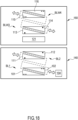
- Figure 18 shows another embodiment wherein the second adjustable birefringent device 140, identical or analogous to the one of figure 2 , is employed and the compensation function is obtained by a third compensation optical device 160 which replaces the first compensation optical device 120 of figure 2 .
- the third compensation optical device 160 includes a first adjustable compensation wedge pair BLW3 (which replaces the first compensation birefringent plate BL3 of figure 2 ), coupled with the polarization flipper 121.
- the third compensation optical device 160 also includes a second adjustable compensation wedge pair BLW4 (which replaces the second compensation birefringent plate BL4 of figure 2 ), coupled with the first adjustable compensation wedge pair BLW3.
- BLW4 which replaces the second compensation birefringent plate BL4 of figure 2
- the first adjustable compensation wedge pair BLW3 (which can be analogous to one of the previous described wedge pairs) includes a fifth optical wedge 113 and a sixth optical wedge 114.
- the first adjustable compensation wedge pair BLW3 defines the thickness t3.
- the second adjustable compensation wedge pair BLW4 includes a seventh optical wedge 115 and an eight optical wedge 116.
- the second adjustable compensation wedge pair BLW4 defines the thickness t4.
- the interferometer apparatus 100 including the components shown figure 18 is operated so as to meet the above defined thickness-sum condition (considering that the components BL1, BL2 and BLW3 and BLW4 have adjustable thicknesses).
- the embodiment of figure 18 is particularly advantageous since ensures a high delay range leading to a better spectral resolution with a full compensation of the angle dependency of the time delay between the replicas.
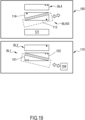
- the adjustable wedge pair BL2 of figure 18 is replaced with a plate as the one of figure 1 , so employing the first adjustable birefringent device 110 of figure 1 which replaces the second adjustable birefringent device 140.
- the second adjustable compensation wedge pair BLW4 is replaced by the second compensation birefringent plate BL4, as the one shown in figure 1 .
- Figure 20 shows a second example of implementation, wherein the second adjustable birefringent device 140 includes a first birefringent plate BLP1, that replaces the adjustable wedge pair BL1 of figure 18 .
- the third compensation optical device 160 it includes a second birefringent plate BLP3 that replaces the first adjustable compensation wedge pair BLW3 of figure 18 .
- the first birefringent plate BLP1 is analogous to the second compensation birefringent plate BL4
- the second birefringent plate BLP3 is analogous to the first compensation birefringent plate BL3.
- the interferometer apparatuses 100 including the components of figure 19 or 20 can be operated so as to meet the above defined thickness-sum condition.
- the described embodiments of the interferometer apparatus 100 allows producing delayed replicas having orthogonal polarizations wherein the delay is not strongly influenced by the propagating angle and by the entering position of the input radiation with respect to the propagation axis travelling in the center of each optical element of the interferometer. Moreover, the two obtained replicas are substantially (according to the meaning already described) parallel having no separating angle.
Landscapes
- Physics & Mathematics (AREA)
- General Physics & Mathematics (AREA)
- Engineering & Computer Science (AREA)
- Mechanical Engineering (AREA)
- Stackable Containers (AREA)
Applications Claiming Priority (1)
| Application Number | Priority Date | Filing Date | Title |
|---|---|---|---|
| IT102023000005346A IT202300005346A1 (it) | 2023-03-21 | 2023-03-21 | Apparato interferometrico |
Publications (1)
| Publication Number | Publication Date |
|---|---|
| EP4435375A1 true EP4435375A1 (de) | 2024-09-25 |
Family
ID=86657144
Family Applications (1)
| Application Number | Title | Priority Date | Filing Date |
|---|---|---|---|
| EP24164048.1A Pending EP4435375A1 (de) | 2023-03-21 | 2024-03-18 | Interferometervorrichtung |
Country Status (3)
| Country | Link |
|---|---|
| US (1) | US20240318952A1 (de) |
| EP (1) | EP4435375A1 (de) |
| IT (1) | IT202300005346A1 (de) |
Citations (9)
| Publication number | Priority date | Publication date | Assignee | Title |
|---|---|---|---|---|
| CA827410A (en) * | 1969-11-18 | International Business Machines Corporation | Variable compensator and interferometer | |
| US3849001A (en) | 1971-06-18 | 1974-11-19 | Hitachi Ltd | Polarization interference correlation spectrometer |
| US5157458A (en) | 1989-03-03 | 1992-10-20 | Buhler Ag | Polarization interferometer spectrometer |
| US20050237532A1 (en) * | 2002-07-02 | 2005-10-27 | Qinetiq Limited | Imaging apparatus |
| US20130329228A1 (en) | 2012-06-07 | 2013-12-12 | Consiglio Nazionale Delle Ricerche | Phase-locked delay device including an optical wedge pair |
| US20150355027A1 (en) | 2013-01-24 | 2015-12-10 | Lambda-X | Hyperspectral imaging |
| WO2018115446A1 (en) | 2016-12-22 | 2018-06-28 | Politecnico Di Milano | Apparatus for measuring optical activity and/or optical anisotropy |
| US20210181022A1 (en) * | 2018-08-23 | 2021-06-17 | Politecnico Di Milano | Fourier-transform hyperspectral imaging system |
| US11181423B2 (en) | 2017-04-07 | 2021-11-23 | Politecnico Di Milano | Birefringent interferometer for measuring photoluminescence properties of samples |
-
2023
- 2023-03-21 IT IT102023000005346A patent/IT202300005346A1/it unknown
-
2024
- 2024-03-18 EP EP24164048.1A patent/EP4435375A1/de active Pending
- 2024-03-20 US US18/611,158 patent/US20240318952A1/en active Pending
Patent Citations (10)
| Publication number | Priority date | Publication date | Assignee | Title |
|---|---|---|---|---|
| CA827410A (en) * | 1969-11-18 | International Business Machines Corporation | Variable compensator and interferometer | |
| US3849001A (en) | 1971-06-18 | 1974-11-19 | Hitachi Ltd | Polarization interference correlation spectrometer |
| US5157458A (en) | 1989-03-03 | 1992-10-20 | Buhler Ag | Polarization interferometer spectrometer |
| US20050237532A1 (en) * | 2002-07-02 | 2005-10-27 | Qinetiq Limited | Imaging apparatus |
| US20130329228A1 (en) | 2012-06-07 | 2013-12-12 | Consiglio Nazionale Delle Ricerche | Phase-locked delay device including an optical wedge pair |
| US20150355027A1 (en) | 2013-01-24 | 2015-12-10 | Lambda-X | Hyperspectral imaging |
| WO2018115446A1 (en) | 2016-12-22 | 2018-06-28 | Politecnico Di Milano | Apparatus for measuring optical activity and/or optical anisotropy |
| US11181423B2 (en) | 2017-04-07 | 2021-11-23 | Politecnico Di Milano | Birefringent interferometer for measuring photoluminescence properties of samples |
| US20210181022A1 (en) * | 2018-08-23 | 2021-06-17 | Politecnico Di Milano | Fourier-transform hyperspectral imaging system |
| US11346719B2 (en) | 2018-08-23 | 2022-05-31 | Politecnico Di Milano | Fourier-transform hyperspectral imaging system |
Non-Patent Citations (4)
| Title |
|---|
| A. R HARVEY ET AL., BIREFRINGENT FOURIER-TRANSFORM IMAGING SPECTROMETER, vol. 12, 2004, pages 5368 - 5374 |
| CHUNMIN ZHANG: "Design and analysis of wide-field-of-view polarization imaging spectrometer", OPTICAL ENGINEERING, vol. 49, no. 4, 1 April 2010 (2010-04-01), BELLINGHAM, pages 043002, XP055652463, ISSN: 0091-3286, DOI: 10.1117/1.3386079 * |
| PERRI ANTONIO ET AL: "A hyperspectral camera for conservation science, based on a birefringent ultrastable common path interferometer", SPIE PROCEEDINGS; [PROCEEDINGS OF SPIE ISSN 0277-786X], SPIE, US, vol. 11058, 12 July 2019 (2019-07-12), pages 110580B - 110580B, XP060122860, ISBN: 978-1-5106-3673-6, DOI: 10.1117/12.2525580 * |
| QUAN NAICHENG ET AL: "Modified Savart polariscope with wide field of view and achromatic lateral displacement", OPTICS COMMUNICATIONS, ELSEVIER, AMSTERDAM, NL, vol. 382, 18 August 2016 (2016-08-18), pages 392 - 398, XP029757648, ISSN: 0030-4018, DOI: 10.1016/J.OPTCOM.2016.07.006 * |
Also Published As
| Publication number | Publication date |
|---|---|
| US20240317458A1 (en) | 2024-09-26 |
| IT202300005346A1 (it) | 2024-09-21 |
| US20240318952A1 (en) | 2024-09-26 |
Similar Documents
| Publication | Publication Date | Title |
|---|---|---|
| US6421131B1 (en) | Birefringent interferometer | |
| JP5599790B2 (ja) | 一つのレーザ光源を用いたダブル光ピンセットの光干渉およびクロストークを低減させる方法、およびその装置 | |
| JP7716977B2 (ja) | スナップショットエリプソメータ | |
| US9625369B2 (en) | Polychromatic polarization state generator and its application for real-time birefringence imaging | |
| KR102430925B1 (ko) | 공간 광 변조기를 이용한 박막의 두께 및 물성 측정 시스템 | |
| US11346719B2 (en) | Fourier-transform hyperspectral imaging system | |
| US20160259158A1 (en) | Polarization-independent differential interference contrast optical arrangement | |
| EP2672244B1 (de) | Phasenverriegelte Verzögerungsvorrichtung mit zwei optischen Keilpaaren | |
| CN111928781B (zh) | 一种基于古斯汉森位移的调控装置及调控方法 | |
| GB2460502A (en) | Wave mixing apparatus for sample analysis | |
| CN102981268B (zh) | 一种横向剪切量可调的双折射晶体分束器 | |
| JP2010002846A (ja) | 複像偏光素子群 | |
| US20240318952A1 (en) | Interferometer apparatus | |
| Wang et al. | Spectral features of guided mode resonant filter with two-dimensional crossed grating | |
| JP2009014418A (ja) | 分光器 | |
| US11391666B1 (en) | Snapshot ellipsometer | |
| KR20180129078A (ko) | 타원해석기 | |
| Chatterjee et al. | Un-polarized light transmission DIC microscope | |
| Rahman et al. | Dispersion of piezo-optic constants of some alkali halides in the ultraviolet region. I. Determination of absolute values | |
| US9778019B2 (en) | Differential polarization interferometer | |
| Quan et al. | Modified Savart polariscope with wide field of view and achromatic lateral displacement | |
| Litwin et al. | Automated variable wavelength interferometry in reflected light mode | |
| Emam-Ismail | Wide spectral range multiple orders and half-wave achromatic phase retarders fabricated from two lithium tantalite single crystal plates | |
| Ai et al. | Optical throughput of the tempo-spatially modulated polarization interference imaging spectrometer | |
| Wang et al. | Broadband snapshot complete polarization imaging based on dual modified Sagnac-grating interferometers |
Legal Events
| Date | Code | Title | Description |
|---|---|---|---|
| PUAI | Public reference made under article 153(3) epc to a published international application that has entered the european phase |
Free format text: ORIGINAL CODE: 0009012 |
|
| STAA | Information on the status of an ep patent application or granted ep patent |
Free format text: STATUS: THE APPLICATION HAS BEEN PUBLISHED |
|
| AK | Designated contracting states |
Kind code of ref document: A1 Designated state(s): AL AT BE BG CH CY CZ DE DK EE ES FI FR GB GR HR HU IE IS IT LI LT LU LV MC ME MK MT NL NO PL PT RO RS SE SI SK SM TR |
|
| STAA | Information on the status of an ep patent application or granted ep patent |
Free format text: STATUS: REQUEST FOR EXAMINATION WAS MADE |
|
| 17P | Request for examination filed |
Effective date: 20250324 |