EP4435367A1 - Vorrichtung , um den ladestatus eines wärmespeichers zu ermitteln - Google Patents
Vorrichtung , um den ladestatus eines wärmespeichers zu ermitteln Download PDFInfo
- Publication number
- EP4435367A1 EP4435367A1 EP24164708.0A EP24164708A EP4435367A1 EP 4435367 A1 EP4435367 A1 EP 4435367A1 EP 24164708 A EP24164708 A EP 24164708A EP 4435367 A1 EP4435367 A1 EP 4435367A1
- Authority
- EP
- European Patent Office
- Prior art keywords
- sst
- mcp
- tank
- vibrating blade
- detector
- Prior art date
- Legal status (The legal status is an assumption and is not a legal conclusion. Google has not performed a legal analysis and makes no representation as to the accuracy of the status listed.)
- Pending
Links
Images


Classifications
-
- F—MECHANICAL ENGINEERING; LIGHTING; HEATING; WEAPONS; BLASTING
- F28—HEAT EXCHANGE IN GENERAL
- F28D—HEAT-EXCHANGE APPARATUS, NOT PROVIDED FOR IN ANOTHER SUBCLASS, IN WHICH THE HEAT-EXCHANGE MEDIA DO NOT COME INTO DIRECT CONTACT
- F28D20/00—Heat storage plants or apparatus in general; Regenerative heat-exchange apparatus not covered by groups F28D17/00 or F28D19/00
- F28D20/02—Heat storage plants or apparatus in general; Regenerative heat-exchange apparatus not covered by groups F28D17/00 or F28D19/00 using latent heat
- F28D20/028—Control arrangements therefor
-
- F—MECHANICAL ENGINEERING; LIGHTING; HEATING; WEAPONS; BLASTING
- F28—HEAT EXCHANGE IN GENERAL
- F28D—HEAT-EXCHANGE APPARATUS, NOT PROVIDED FOR IN ANOTHER SUBCLASS, IN WHICH THE HEAT-EXCHANGE MEDIA DO NOT COME INTO DIRECT CONTACT
- F28D7/00—Heat-exchange apparatus having stationary tubular conduit assemblies for both heat-exchange media, the media being in contact with different sides of a conduit wall
- F28D7/16—Heat-exchange apparatus having stationary tubular conduit assemblies for both heat-exchange media, the media being in contact with different sides of a conduit wall the conduits being arranged in parallel spaced relation
-
- F—MECHANICAL ENGINEERING; LIGHTING; HEATING; WEAPONS; BLASTING
- F28—HEAT EXCHANGE IN GENERAL
- F28F—DETAILS OF HEAT-EXCHANGE AND HEAT-TRANSFER APPARATUS, OF GENERAL APPLICATION
- F28F1/00—Tubular elements; Assemblies of tubular elements
- F28F1/10—Tubular elements and assemblies thereof with means for increasing heat-transfer area, e.g. with fins, with projections, with recesses
- F28F1/12—Tubular elements and assemblies thereof with means for increasing heat-transfer area, e.g. with fins, with projections, with recesses the means being only outside the tubular element
- F28F1/24—Tubular elements and assemblies thereof with means for increasing heat-transfer area, e.g. with fins, with projections, with recesses the means being only outside the tubular element and extending transversely
-
- G—PHYSICS
- G01—MEASURING; TESTING
- G01F—MEASURING VOLUME, VOLUME FLOW, MASS FLOW OR LIQUID LEVEL; METERING BY VOLUME
- G01F23/00—Indicating or measuring liquid level or level of fluent solid material, e.g. indicating in terms of volume or indicating by means of an alarm
- G01F23/22—Indicating or measuring liquid level or level of fluent solid material, e.g. indicating in terms of volume or indicating by means of an alarm by measuring physical variables, other than linear dimensions, pressure or weight, dependent on the level to be measured, e.g. by difference of heat transfer of steam or water
- G01F23/28—Indicating or measuring liquid level or level of fluent solid material, e.g. indicating in terms of volume or indicating by means of an alarm by measuring physical variables, other than linear dimensions, pressure or weight, dependent on the level to be measured, e.g. by difference of heat transfer of steam or water by measuring the variations of parameters of electromagnetic or acoustic waves applied directly to the liquid or fluent solid material
- G01F23/296—Acoustic waves
- G01F23/2966—Acoustic waves making use of acoustical resonance or standing waves
- G01F23/2967—Acoustic waves making use of acoustical resonance or standing waves for discrete levels
Definitions
- the invention relates to the field of Thermal Storage Systems (TSS) by Phase Change Materials (PCM), and more particularly, the integration of a device for measuring the state of charge of the system.
- TSS Thermal Storage Systems
- PCM Phase Change Materials
- the invention will find its application more particularly for all SSTs having an interface between the PCM and a gas sky.
- the invention will find its application for example in urban, rural or industrial heating and/or cooling networks as well as in the storage of solar energy.
- the invention may also find applications in housing or even off-grid thermal transport (trucks, boats, etc.).
- Thermal storage can be achieved by a change of state characterized by a transformation enthalpy.
- storage is done by phase change material. It is the phase change enthalpy that is stored.
- the charge of the heat storage system is accompanied by the melting of the storage material, while the discharge is achieved by the solidification of said material. It is the opposite when considering a storage of frigories for a cold network.
- phase change occurs at a constant temperature. Therefore, the discharge of the stored energy can occur at a nearly constant temperature and close to the phase change temperature of the material.
- phase change enthalpy is relatively large compared to the sensible energy variation of a material. Therefore, storage systems with MCP are interesting because the amount of energy stored per unit volume (and mass) is greater than that obtained by a sensible system (better storage density). As a result, the storage and material volumes are reduced, which limits thermal losses which are proportional to the external surface of the tank.
- a system for implementing latent heat storage is the use of shell and tube technology exchangers.
- a shell in which a fluid circulates is traversed by a bundle of tubes in which another fluid flows.
- the two fluids exchange energy by conduction through the thickness of the tubes.
- this technology is suitable, there is no longer an exchange between two fluids in motion, but between a heat transfer fluid which circulates in the tubes and the MCP which is fixed in the shell (apart from the movements of natural convection in the liquid phase).
- the heat transfer fluid reaches a temperature higher than the temperature melting point of the MCP and releases energy to it, which causes it to melt; during discharge, the heat transfer fluid enters at a temperature lower than the melting temperature of the MCP and recovers the previously stored energy, which causes the MCP to solidify.
- thermal storage is obvious, particularly in the field of heating and cooling networks.
- a relevant use of such a device depends largely on the capacity of the network manager to be able to implement a real energy strategy based on technical and economic data of consumption/production in real time, as well as on adapted forecasts. In this logic, the manager will thus be able to choose rationally when to charge or discharge his storage means.
- the implementation of this usage strategy is only feasible if the state of charge or the charge rate (i.e. the quantity of calories or frigories stored) of the storage system is known.
- measuring the state of charge of a thermal storage by latent heat is problematic, because the heat is stored at a constant temperature, it is therefore difficult to quantify it using temperature detectors.
- One way to determine the charge status of a thermal storage system is to record its operating history. To do this, the amount of energy injected or withdrawn from the storage system is measured using a flow meter and temperature detectors placed in the heat transfer fluid circuit, at the inlet and outlet of the thermal storage system. By knowing the initial charge status when the storage system is commissioned, it is therefore theoretically possible to determine the charge status of the storage system following various operations.
- the Austrian laboratory ASiC proposes to measure the charge rate of a latent storage tank by measuring the pressure of the tank's headspace. This idea is based on the fact that the MCPs used exhibit a high volume expansion during their fusion (from 5% to 15%). A pressure increase therefore takes place in the headspace between the fully solid state and the fully liquid state. It is thus possible to correlate the pressure measured in the headspace with the fraction of liquid formed and therefore to determine the charge rate. In practice, this This method has many drawbacks. First, it requires perfect sealing of the storage volume in order to be able to observe the pressure variation. In addition, these pressure variations subject the tank to strong pressure increases which have an impact on the design of the tank. Furthermore, the influence of temperature on the pressure of the gas head must also be taken into account, because its impact can be significant. This aspect can have a significant impact on the cost of the device.
- Measuring the loading rate by measuring the gas flow rate that leaves/enters the gas headspace during the fusion/solidification cycles has also been proposed.
- This measurement method has the advantages of being non-intrusive and not being disturbed by thermal losses from storage.
- this device has several drawbacks: the estimation of the loading rate is based on the integration over time of a flow rate that will necessarily have a measurement uncertainty, it is necessary to ensure a costly and complex sealing of the tank.
- the charge rate (or state of charge) of a thermal storage corresponds to the share of useful thermal energy still available divided by the total storable thermal energy.
- the useful thermal energy available in a so-called latent storage medium is the sum of the sensible and latent energies of the system.
- the portion of sensible energy available in a latent storage system is easily measurable by one or more temperature probes.
- the importance of this portion of energy depends on the heat capacity of the material used and the difference between the system temperature and that of the source (hot or cold) of the application. The greater this difference, the higher the share of sensible energy stored will be.
- the latent thermal energy available in a latent storage system corresponds to the mass of the liquid PCM present multiplied by its latent heat of phase change (solid-liquid).
- the total storable latent thermal energy corresponds to the total mass of PCM multiplied by its latent heat.
- the total mass of MCP is constant and known since it is one of the design and dimensioning parameters of the thermal energy storage system. It is therefore sufficient to be able to determine the mass of liquid. However, the mass of liquid can be easily determined from the volume occupied by this liquid if its liquid density is known.
- the device according to the invention has a determination of the charge rate which is more precise in particular than the prior art taking into consideration the liquid/solid interface.
- the risks of false measurements are limited since the vibrating blade detects the liquid MCP/gas head separation front, there is therefore no contact with the solid MCP and there is therefore no risk that the solid MCP by detaching from the wall of the tank induces measurement errors.
- the device according to the invention allows a direct physical measurement without integration over time. There is therefore no drift of the determination device over time.
- the device is applicable to tanks whose gas head is closed or open.
- the determination device is very slightly intrusive facilitating its implementation and limiting the impacts on the operation of the SST.
- the vibrating blade passes through the side wall.
- the vibrating blade comprises a part inside the tank and a part outside the tank.
- the vibrating blade is for example screwed from the outside of the tank onto the side wall, it is therefore inspectable and removable in the event of a breakdown or for replacement.
- the accuracy of the determination of the load rate can be easily increased by modulating the number of vibrating blades.
- the device or SST comprises a plurality of vibrating blade detectors arranged at different heights in the measurement zone.
- This device thus makes it possible to determine the charge rate, whatever the state of charge of the means of storing energy by latent heat.
- the invention relates to a method for determining a charge rate of an SST comprising receiving the signal provided by the at least one vibrating blade detector, then determining the charge rate, advantageously at said determined moment, as a function of the signal provided by each vibrating blade detector and their predefined height in the measurement zone.
- the determination device, the associated SST and the determination method according to the invention are particularly effective since they make it possible to obtain the liquid mass of MCP directly and they do not need to go through theoretical calculations taking into account the expansion coefficient of the MCP and/or the volume occupied by a measuring fluid.
- the determination is therefore simple and rapid with optimized precision and a very limited risk of error without risk of measurement drift over time.
- the method comprises placing a plurality of vibrating blade detectors 200 in the measurement area 203 at different predefined heights.
- 'top' and ⁇ bottom' mean a quality of relative positioning of a device element for determining a charge rate or of the thermal storage system when the latter is functionally installed, the ⁇ top' being oriented away from the ground and the 'bottom' being oriented towards the ground.
- the upper end is located at the top and the lower end is located at the bottom.
- a transverse direction is a direction perpendicular to a longitudinal direction.
- a transverse section is a section perpendicular to the longitudinal axis.
- Upstream and downstream, inlet, outlet, at a given point are taken in reference to the direction of circulation of the fluid.
- a parameter "substantially equal to/greater than/less than” or “of the order of” a given value means that this parameter is equal to/greater than/less than the given value, to within plus or minus 10%, or even to within plus or minus 5%, of this value.
- Fluidly connected or in fluid connection is understood to mean when a line provides a connection through or in which a fluid circulates.
- hot, cold, cooled we mean a temperature relative to another point in the system.
- the invention relates to a system for determining a charge rate of a Thermal Storage System (TSS).
- TSS Thermal Storage System
- the invention also relates to a thermal storage system (TSS) comprising the device for determining the charge rate.
- the device for determining the charge rate is applicable to a latent heat thermal storage system.
- Thermal energy storage allows heat to be used at a later time.
- Heat can be stored in several forms.
- the invention focuses on storage in the form of latent heat with the use of phase change materials that store energy as they change phase. When the material reaches its phase change temperature, it absorbs a quantity of heat to carry out the transformation, known as the latent heat of fusion or vaporization as the case may be. Conversely, when the liquid or gas material is cooled, it returns to the solid or liquid phase by giving off its latent heat.
- the latent heat of fusion is lower than the latent heat of evaporation, the solid-liquid transition is the most promising since it allows limiting the volume expansion and thus the increase in pressure due to the phase change.
- Solid/liquid MCPs are understood as materials that change phase between a solid state and a liquid state depending on its temperature. When its temperature is above its melting temperature, the MCP is in the liquid state and when its temperature is below its melting temperature, the MCP is in the solid state.
- the MCPs are chosen from solid/liquid MCPs exhibiting a volume variation during the phase change.
- the volume variation is at least of the order of 5%, preferably of the order of 10 to 20%.
- the MCPs are chosen from organic compounds and in particular fatty alcohols, fatty acids and paraffins or from inorganic compounds such as molten salts, liquid metals or salt hydrates.
- the MCP may be a single MCP or a mixture of several MCPs. In the remainder of the description, the use of the term MCP is not limiting.
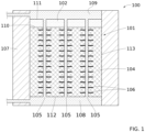
- the thermal energy storage system comprises a tank of storage 101 intended to receive the MCP, as described above.
- the tank 101 is also called a calender.
- the tank 101 is preferably cylindrical for reasons of mechanical strength.
- the tank 101 comprises at least one side wall 113, in particular when the tank is cylindrical.
- the tank 101 may comprise several side walls 113 when it has another geometry, for example of the parallelepiped type.
- the tank 101 also comprises a lower wall 112 and possibly an upper wall 111, depending on whether the tank 101 is open or closed.
- the thermal storage system also comprises a heat exchanger immersed in the tank 101.
- the heat exchange is intended for the circulation of a heat transfer fluid from an external heat transfer fluid circulation network to store and extract heat from the MCP.
- the heat transfer fluid is a single-phase fluid under the operating conditions of the SST, most often water or pressurized water, but it can also be air, a thermal oil or even a molten salt.
- the thermal energy storage system according to the invention is thus of the shell-tube type.
- the heat exchanger preferably comprises a bundle of tubes 105, in particular with fins 106, assembled between a lower distributor 108 and an upper collector 109.
- the heat transfer fluid circulates inside the tubes 105 and exchanges its heat with the MCP 103, 104 contained in the tank 101.
- the tank 101 extends in a main vertical direction.
- the heat exchanger extends in a vertical direction
- the tube bundle 105 extends vertically between the lower distributor 108 and the upper distributor 109, preferably respectively arranged at the lower and upper ends of the tank 101.
- the lower distributor 108 and the upper distributor 109 are connected to an external heat transfer fluid circulation network respectively by a heat transfer fluid inlet or outlet pipe.
- the upper distributor 109 and the lower distributor 108 may respectively form at least partially the upper wall 111 and the lower wall 112 of the tank 101.
- the upper wall 111 of the tank 101 is advantageously formed by a cover.
- the tank 101 is configured to allow it to be filled.
- the tank 101 may comprise a removable cover to allow it to be filled or a cover provided with filling hatches or the tank comprises a hatch on a shell on the side of the system.
- the tank 101 of the SST comprises a gas sky 102.
- the gas sky 102 is arranged above the MCP 103,104.
- the gas ceiling 102 is located between the upper surface of the MCP 103,104 and the upper wall 111 of the tank 101, which may be formed by the upper distributor 109, in particular by the lower plate of the upper distributor 109.
- the device for determining the charge rate according to the invention takes into consideration the separation front 110 of the MCP 103,104 with the gas sky 102.
- the separation front 110 of the MCP 103,104 with the gas sky 102 is understood as the interface between the gas sky 102 and the MCP 103,104 in contact with the gas sky 102, that is to say either the MCP 104 in the liquid state, or the MCP in the solid state 103 depending on the operating phases of the SST.
- the position, in the tank, of the separation front 110 is intended to be representative of the SST charge rate.
- the device for determining the charge rate does not require the presence of an additional measuring fluid other than the liquid/solid MCP. It has indeed been surprisingly found that the measuring fluid is not necessary to enable the monitoring of the separation front 110 of the MCP with the gas ceiling.
- the separation front 110 of the MCP 103, 104 with the gas ceiling 102 is substantially flat, advantageously parallel to the horizontal, advantageously over the entire cross section of the tank 100.
- the position of the separation front 110 in the tank varies according to the volume variations of the MCP. These volume variations are mainly due to the phase change of the MCP: that is to say due to the melting or solidification of the MCP. It is thus understood that the position of the separation front 110 makes it possible to determine the volume and therefore the mass of liquid MCP at a time T.
- the SST when the MCP is substantially entirely in a solid state, the SST is then completely discharged, the separation front 110 then taking a position defining a first height level 201. Conversely, when the MCP is substantially entirely in a liquid state, the SST is then completely charged, the separation front 110 then taking a position defining a second height level 202.
- the separation front 110 therefore takes a position between the first height level 201 and the second height level 202.
- the height between the first height level 201 and the second height level 202 is the lowest level of the separation front 110 in the tank 101.
- height 201 and the second height level 202 defines a measurement zone 203.
- the measurement zone 203 therefore corresponds to the positioning amplitude of the separation front 110 during operation of the SST 100.
- the thermal storage system and the device for determining a charge rate are configured so that the measurement zone 203 is at least 25 cm high.
- the measurement zone 203 which alternately sees liquid MCP 104 and gas sky 102 in the top of a tank 101 comprising 10 m of MCP, has a height of 1 to 1.5 m, considering a volume expansion of the MCP typically of the order of 10-15%.
- the determination device comprises at least one vibrating blade detector 200.
- the vibrating blade 200 is intended to be arranged in the measurement zone 203.
- the vibrating blade 200 intended to be alternately in contact with the gas sky 102 or the liquid MCP 104.
- the vibrating blade intended to be arranged in the measurement zone 203 with the exception of the first height level 201, so that the vibrating blade 200 is alternately in contact with the liquid MCP 104 and the gas sky 102 without coming into contact with the solid MCP 103.
- the vibrating blade detector 200 is advantageously a detector making it possible to detect the presence of the gas ceiling 102 or the liquid MCP 104, preferably by an all-or-nothing binary signal TOR on the basis of a signal equal to zero for the presence of the gas ceiling 102 and a signal equal to one for the presence of the liquid MCP 104.
- the vibrating blade detector 200 is advantageously a point detector intended to detect the presence of the gas ceiling 102 or the liquid MCP 104 continuously.
- the device for determining a load rate comprises a plurality of vibrating blade detectors 200 arranged at different heights in the measurement area 203.
- the device comprises 5 vibrating blade detectors arranged as described below, the position of each vibrating blade 200 in the measurement area 203 corresponds to a certain load rate of the SST, the position of the vibrating blade 2001 corresponding to the first height level 201 makes it possible to determine a load rate of the order of 0%; the position of the vibrating blade 2005 corresponding to the second height level 202 makes it possible to determine a load rate of the order of 100%; the position of the vibrating blade 2003 corresponding to 50% of the height of the measurement area 203 makes it possible to determine a load rate of the order of 50%; the position of the vibrating blade 2002 corresponds to 25% of the height of the measuring zone 203 allows to determine a load rate of the order of 25%; the position of the vibrating blade 2004 corresponds to 75% of the height of the measuring zone 203 makes it possible to determine a load rate of the order
- the height of the measuring zone 203 corresponds to a 100% load rate and the positioning of the vibrating blade 200 in the measuring zone 203 thus corresponds to a corresponding load rate.
- the device for determining the charge rate and the associated SST comprise a plurality of vibrating blades 200.
- the device for determining the charge rate comprises two or more vibrating blades 200.
- the determination device comprises 3 vibrating blade detectors 200, more preferably 4 vibrating blade detectors 200, preferably 5 vibrating blade detectors 200, preferably 6 vibrating blade detectors 200, preferably 7 vibrating blade detectors 200, preferably 8 vibrating blade detectors 200, preferably 9 vibrating blade detectors 200, preferably 10 vibrating blade detectors 200.
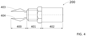
- the vibrating blade 200 is of the type of piezoelectric detector intended for the detection of a liquid or a gas.
- the vibrating blade 200 is advantageously arranged in the tank 100 at a side wall 113.
- the vibrating blade 200 is arranged so as to pass through a side wall 113.
- a tank 100 conventionally comprises bosses in the upper part.
- the vibrating blade 200 is advantageously arranged through bosses of this type. This positioning allows easy installation of the determination device since it does not require intrusive penetration into the tank, and it is thus easy to repair or maintain the vibrating blade 200.
- the vibrating blade detector 200 comprises a first portion 400 comprising the 2 blades 403, 404 and intended to be arranged inside the tank 101, a second portion 401 intended to ensure the connection of the vibrating blade detector 200 to the tank 101, in particular by a screw thread, and a third portion 402 intended to be arranged outside the tank 101 and advantageously comprising an electrical module comprising the piezoelectric element allowing the blades 403, 404 to vibrate and an integration means intended to transform the signal of the vibrations of the blades 403, 404 into an advantageously all-or-nothing signal.
- the determination device comprises an electronic card intended to determine the charge rate as a function of the signal provided by the vibrating blade detector(s) 200 and their position in the measurement zone 203.
- the SST is fully loaded, the MCP 104 is entirely in the liquid state.
- the separation front 110 between the liquid MCP 104 and the gas ceiling 102 is substantially flat and advantageously horizontal.
- the separation front 110 is located at a first height level of 201 relative to the lower wall 112 of the tank 101.
- the tube bundle 105 is supplied from the lower distributor 108 with a cold heat transfer fluid 301.
- Cold means that the heat transfer fluid is at a temperature lower than the melting temperature of the MCP.
- the solidification of the liquid MCP 104 begins.
- the liquid MCP 104 transfers its thermal energy to the cold heat transfer fluid 301 which emerges at the upper distributor 109 at a higher temperature level as the heated heat transfer fluid 302.
- the level of liquid MCP 104 begins to drop by volume contraction of the MCP in the lower part of the tank 101.
- the separation front between the MCP and the gas ceiling 102 remains a flat and horizontal liquid/gas interface.
- the change in height of the separation front 110 between the first height level 201 and the second height level 202 is representative of the fraction of liquid MCP 104 in the tank 101 and therefore of the state of charge of the SST.
- FIGS 3A, 3B , 3C and 3D is illustrated the tank 101 during a charge of the SST comprising a determination device according to the invention comprising five vibrating blade detectors 200.
- the MCP 103 undergoes a fusion, that is to say it passes from the solid state to the liquid state.
- the tube bundle 105 is supplied from the upper distributor 109 with a hot heat transfer fluid 303.
- hot is meant that the heat transfer fluid is at a temperature higher than the melting temperature of the PCM.
- the melting of the solid PCM 103 begins.
- the hot heat transfer fluid 303 transfers its thermal energy to the solid PCM 103.
- the cooled heat transfer fluid 304 exits the tank 101 at the lower distributor 108 at a temperature level lower than that of its inlet.
- the solid PCM 103 transforms into liquid PCM 104 in the upper part of the tank 101.
- This change phase of the MCP creates the separation front 110 between the MCP and the gas sky 102 with a flat and horizontal liquid MCP 104/air interface.
- the liquid MCP level 104 begins to increase by volume expansion of the liquefying MCP 103.
- the separation front 110 begins to move.
- the fusion/solidification profile contributes to the fact that the determination device according to the invention and the associated SST do not require the presence of a measuring fluid since the separation front between the MCP and the gas ceiling 102 is naturally flat and horizontal.
- five vibrating blade detectors 2001, 2002, 2003, 2004, 2005 are arranged in the measurement area 203.
- the vibrating blades are arranged such that the first vibrating blade 2001 is arranged at a height level above the first height level 201 corresponding to 10% of the height of the area 203, the second vibrating blade 2002 is arranged at a height level above the first height level 201 corresponding to 30% of the height of the area 203, the third vibrating blade 2003 is arranged at a height level above the first height level 201 corresponding to 50% of the height of the area 203, the fourth vibrating blade 2004 is arranged at a height level above the first height level 201 corresponding to 70% of the height of the zone 203, the fifth vibrating blade 2005 is arranged at a height level above the first height level 201 corresponding to 90% of the height of the zone 203.
- the invention relates to a method of setting up a device for determining a load rate of an SST.
- This method of setting up the determination device comprises a first phase of defining the measurement zone 203 in which at least one vibrating blade detector 200 must be arranged.
- this first phase of defining the measurement zone 203 is carried out by calculation.
- this first phase of defining the measurement zone 203 is carried out on the installed SST.
- this first definition phase comprises several successive steps. First, the SST is completely discharged. The MCP 103 is entirely in the solid state. Then, the first height level 201 of the separation front 110 is measured. The height of the interface between the solid MCP 103 and the gas ceiling 102, corresponding to the separation front 110 in this discharged state, is measured from the upper wall 111 of the tank, preferably, that is to say from the bottom of the tank 101. This height 201 corresponds to the height of the solid MCP 103 in this discharged state. Then, the SST is completely loaded.
- the MCP 104 is substantially entirely in the liquid state.
- the second height level 202 of the separation front 110 is measured.
- the height of the interface between the liquid MCP 104 and the gas ceiling 102, corresponding to the separation front 110 in this charged state, is measured from the upper wall 111 of the tank preferably, that is to say from the bottom of the tank 101.
- This height 202 corresponds at the height of the liquid MCP 104 in this charged state.
- the measuring zone 203 is located between the first height level 201 and the second height level 202.
- the method for positioning the determination device advantageously comprises a second phase of positioning at least one vibrating blade detector 200 in the measurement zone 203 on a side wall 113 of the tank 101 at a predefined height.
- the method of setting up the determination device comprises repeating the second phase of positioning at least one vibrating blade detector 200 for each other vibrating blade detector 200 intended to be arranged in the measurement zone 203 at a different height.
- the invention relates to a method for determining a charge rate of an SST.
- the method for determining the charge rate of the SST comprises receiving the signal provided by one or more vibrating blade detectors 200, advantageously by the electronic card, then determining the charge rate as a function of the signal provided by each vibrating blade detector 200 and their height in the measurement zone 203.
- the electronic card provides a charge rate as a percentage preferably between 10 and 90%, preferably between 5 and 95%.
- the determination of a charge rate of an SST is carried out continuously.
- the first phase of defining the measurement zone 203 can be carried out again after a certain number of charge-discharge cycles to ensure that the first height level 201 and the second height level 202 have not varied due to the degradation of the quality of the MCP.
- a thermal storage system 100 consists of a bundle of tubes 105 included in a calender, or tank, 101 mounted on a stand.
- the calender is closed at the top and bottom by domed bottoms.
- the tank 101 is intended to receive the MCP 103,104 from the fatty alcohol family.
- the tank 101 comprises around 8.8 tonnes of MCP 103,104.
- the bundle of tubes 105 consists of 361 finned tubes with a total length of 9000 mm for a length of tubes with fins of 8600 mm.
- the SST has a total overall height of 12 m for a diameter of 1.40 m.
- the SST is configured for the storage of 800 kW.h.
- the first height level 201 when the MCP 103 is fully solid is 7600 mm.
- the second height level 202 when the MCP 104 is fully liquid is 8600 mm.
- the first height level 201 and the second height level 202 are measured from the bottom distribution plate of the tank in contact with the MCP.
- the charge rate of the SST is less than 5%.
- the charge rate of the SST is greater than 95%.
- the charge rate is between 45 and 55%.
Landscapes
- Physics & Mathematics (AREA)
- Engineering & Computer Science (AREA)
- Thermal Sciences (AREA)
- Mechanical Engineering (AREA)
- General Engineering & Computer Science (AREA)
- Geometry (AREA)
- Acoustics & Sound (AREA)
- Electromagnetism (AREA)
- Fluid Mechanics (AREA)
- General Physics & Mathematics (AREA)
- Investigating Or Analyzing Materials Using Thermal Means (AREA)
Applications Claiming Priority (1)
| Application Number | Priority Date | Filing Date | Title |
|---|---|---|---|
| FR2302700A FR3147053B1 (fr) | 2023-03-22 | 2023-03-22 | Dispositif de détermination d’un taux de charge d’un Système de Stockage Thermique |
Publications (1)
| Publication Number | Publication Date |
|---|---|
| EP4435367A1 true EP4435367A1 (de) | 2024-09-25 |
Family
ID=86764351
Family Applications (1)
| Application Number | Title | Priority Date | Filing Date |
|---|---|---|---|
| EP24164708.0A Pending EP4435367A1 (de) | 2023-03-22 | 2024-03-20 | Vorrichtung , um den ladestatus eines wärmespeichers zu ermitteln |
Country Status (2)
| Country | Link |
|---|---|
| EP (1) | EP4435367A1 (de) |
| FR (1) | FR3147053B1 (de) |
Citations (4)
| Publication number | Priority date | Publication date | Assignee | Title |
|---|---|---|---|---|
| DE10235581C1 (de) * | 2002-08-03 | 2003-08-21 | Bayerische Motoren Werke Ag | Bestimmung eines Latentwärmespeicher-Ladezustandes, insbesondere in einer Heizungs- und/oder Klimaanlage eines Straßenkraftfahrzeuges |
| WO2016051377A1 (fr) | 2014-10-01 | 2016-04-07 | Commissariat A L'energie Atomique Et Aux Energies Alternatives | Système et procédé de détermination du taux de charge d'un stockage thermique latent |
| EP3264018A1 (de) | 2016-06-27 | 2018-01-03 | Commissariat à l'Energie Atomique et aux Energies Alternatives | Thermisches pcm-speichersystem, das eine messvorrichtung eines repräsentativen parameters des ladungsniveaus umfasst |
| US10281269B2 (en) * | 2012-07-17 | 2019-05-07 | Ihc Holland Ie B.V. | Method and device for determining a height of a settled bed in a mixture in a loading space |
-
2023
- 2023-03-22 FR FR2302700A patent/FR3147053B1/fr active Active
-
2024
- 2024-03-20 EP EP24164708.0A patent/EP4435367A1/de active Pending
Patent Citations (4)
| Publication number | Priority date | Publication date | Assignee | Title |
|---|---|---|---|---|
| DE10235581C1 (de) * | 2002-08-03 | 2003-08-21 | Bayerische Motoren Werke Ag | Bestimmung eines Latentwärmespeicher-Ladezustandes, insbesondere in einer Heizungs- und/oder Klimaanlage eines Straßenkraftfahrzeuges |
| US10281269B2 (en) * | 2012-07-17 | 2019-05-07 | Ihc Holland Ie B.V. | Method and device for determining a height of a settled bed in a mixture in a loading space |
| WO2016051377A1 (fr) | 2014-10-01 | 2016-04-07 | Commissariat A L'energie Atomique Et Aux Energies Alternatives | Système et procédé de détermination du taux de charge d'un stockage thermique latent |
| EP3264018A1 (de) | 2016-06-27 | 2018-01-03 | Commissariat à l'Energie Atomique et aux Energies Alternatives | Thermisches pcm-speichersystem, das eine messvorrichtung eines repräsentativen parameters des ladungsniveaus umfasst |
Non-Patent Citations (1)
| Title |
|---|
| ZSEMBINSZKI, G.OROZCO, C.GASIA, J.BARZ, T.EMHOFER, J.CABEZA, L.F.: "Evaluation of the State of Charge of a Solid/Liquid Phase Change Material in a Thermal Energy Storage Tank", ENERGIES, vol. 13, 2020, pages 1425 |
Also Published As
| Publication number | Publication date |
|---|---|
| FR3147053B1 (fr) | 2025-03-14 |
| FR3147053A1 (fr) | 2024-09-27 |
Similar Documents
| Publication | Publication Date | Title |
|---|---|---|
| EP3264018B1 (de) | Thermisches pcm-speichersystem, das eine messvorrichtung eines repräsentativen parameters des ladungsniveaus umfasst | |
| WO2009053648A2 (fr) | Procede de determination en temps reel du niveau de remplissage d'un reservoir cryogenique | |
| WO2012160293A1 (fr) | Débitmètre pour fluides diphasiques cryogeniques gaz/liquide | |
| FR2944103A1 (fr) | Imagerie tera-hertz a convertisseur infrarouge perfectionne. | |
| EP4435367A1 (de) | Vorrichtung , um den ladestatus eines wärmespeichers zu ermitteln | |
| WO2014202540A1 (fr) | Dispositif et procede d' analyse thermique et calorimetrique differentielle d' echantillons de volumes importants | |
| FR2472177A1 (fr) | Mesureur de niveau pour liquide, notamment pour l'eau de refroidissement d'un reacteur | |
| EP3201555B1 (de) | System und verfahren zur bestimmung des ladezustandes eines latentwärmespeichers | |
| FR3013453A1 (fr) | Procede, jauge et systeme de mesure d'energie thermique dans des materiaux a changement de phase | |
| CA2003714C (fr) | Methode et dispositif d'analyse d'un fluide polyphasique en ecoulement dans une conduite | |
| EP2203729B1 (de) | Zweiphasenübergangs-nuklearkalorimeter für einen reaktor | |
| FR2968448A1 (fr) | Cellule calorimetrique mobile pour mesure d'echauffement en cœur de reacteur nucleaire | |
| EP3479006B1 (de) | Verfahren und system zur echtzeit-berechnung der energiemenge in einem ungekühlten, unter druck stehenden flüssigerdgasbehälter | |
| EP1643230A1 (de) | Verfahren und Vorrichtung zur Kontrolle der Dichtheit eines Mantels enthaltend Druckgas | |
| FR2488991A1 (fr) | Procede et installation pour la mesure de grandeurs d'etat thermique de fluides | |
| EP3628958A1 (de) | Wärmespeichersystem mit phasenwechselmaterialen (pcm), das eine evaluierungsvorrichtung der ladung des wärmespeichersystems umfasst | |
| CA3227362A1 (fr) | Debitmetre pour fluide diphasique | |
| EP3312539A1 (de) | Thermisches mcp-speichersystem, das eine messvorrichtung eines repräsentativen parameters des ladungsniveaus umfasst | |
| WO2022112717A1 (fr) | Procédé et système pour la détermination temporelle d'un niveau d'interface de phase d'un fluide polyphasique présent dans une conduite verticale | |
| WO2014181047A1 (fr) | Dispositif de capture, d'échange et de stockage thermique de l'énergie solaire | |
| FR3112606A1 (fr) | Système à rotor de mesure du débit d’un fluide comportant du liquide, et équipement associé | |
| EP3368852A1 (de) | Vorrichtung zur wärmeenergiespeicherung mittels einer fest-flüssig-speicherstoffes mit einem kondensator | |
| FR3038052A1 (fr) | Procede et dispositif d'estimation de la masse de gaz contenue dans un reservoir de gaz sous pression | |
| WO2011124790A1 (fr) | Dispositif de refroidissement a dephasage passif | |
| FR3111422A1 (fr) | Ensemble comprenant une paroi et un système de mesure sans contact d’une déformation de la paroi, et procédé de mesure associé |
Legal Events
| Date | Code | Title | Description |
|---|---|---|---|
| PUAI | Public reference made under article 153(3) epc to a published international application that has entered the european phase |
Free format text: ORIGINAL CODE: 0009012 |
|
| STAA | Information on the status of an ep patent application or granted ep patent |
Free format text: STATUS: REQUEST FOR EXAMINATION WAS MADE |
|
| 17P | Request for examination filed |
Effective date: 20240320 |
|
| AK | Designated contracting states |
Kind code of ref document: A1 Designated state(s): AL AT BE BG CH CY CZ DE DK EE ES FI FR GB GR HR HU IE IS IT LI LT LU LV MC ME MK MT NL NO PL PT RO RS SE SI SK SM TR |
|
| RAP3 | Party data changed (applicant data changed or rights of an application transferred) |
Owner name: COMMISSARIAT A L'ENERGIE ATOMIQUE ET AUX ENERGIESALTERNATIVES |
|
| GRAP | Despatch of communication of intention to grant a patent |
Free format text: ORIGINAL CODE: EPIDOSNIGR1 |
|
| STAA | Information on the status of an ep patent application or granted ep patent |
Free format text: STATUS: GRANT OF PATENT IS INTENDED |
|
| RIC1 | Information provided on ipc code assigned before grant |
Ipc: F28D 7/16 20060101AFI20260318BHEP Ipc: G01F 23/2965 20220101ALI20260318BHEP |