EP4435330A1 - Adaptive chimney duct - Google Patents
Adaptive chimney duct Download PDFInfo
- Publication number
- EP4435330A1 EP4435330A1 EP24164575.3A EP24164575A EP4435330A1 EP 4435330 A1 EP4435330 A1 EP 4435330A1 EP 24164575 A EP24164575 A EP 24164575A EP 4435330 A1 EP4435330 A1 EP 4435330A1
- Authority
- EP
- European Patent Office
- Prior art keywords
- chimney
- base
- flange
- top cover
- segment
- Prior art date
- Legal status (The legal status is an assumption and is not a legal conclusion. Google has not performed a legal analysis and makes no representation as to the accuracy of the status listed.)
- Withdrawn
Links
Images




Classifications
-
- F—MECHANICAL ENGINEERING; LIGHTING; HEATING; WEAPONS; BLASTING
- F24—HEATING; RANGES; VENTILATING
- F24C—DOMESTIC STOVES OR RANGES ; DETAILS OF DOMESTIC STOVES OR RANGES, OF GENERAL APPLICATION
- F24C15/00—Details
- F24C15/20—Removing cooking fumes
- F24C15/2007—Removing cooking fumes from oven cavities
-
- F—MECHANICAL ENGINEERING; LIGHTING; HEATING; WEAPONS; BLASTING
- F24—HEATING; RANGES; VENTILATING
- F24C—DOMESTIC STOVES OR RANGES ; DETAILS OF DOMESTIC STOVES OR RANGES, OF GENERAL APPLICATION
- F24C15/00—Details
- F24C15/32—Arrangements of ducts for hot gases, e.g. in or around baking ovens
Definitions
- the present disclosure generally relates to a chimney duct assembly, and more specifically, to an adaptive chimney duct assembly for an appliance.
- a cooking appliance includes a body and a cavity housing disposed in the body.
- the cavity housing defines a cooking cavity.
- a self-adjusting chimney duct assembly is disposed in a space defined between the body and the cavity housing.
- the chimney duct assembly includes a chimney base.
- An inlet is defined on a bottom section of the chimney base.
- a base flange is coupled to the chimney base. The base flange biases the chimney base towards the cavity housing.
- a chimney top cover is disposed over and operably coupled to the chimney base.
- An outlet is defined between the chimney base and the chimney top cover. The inlet and the outlet are in fluid communication with the cooking cavity for venting.
- a cover flange is coupled to the chimney top cover and biases the chimney top cover towards the body.
- a cooking appliance ventilation system includes a body with a top section.
- a cavity housing is disposed within the body and includes a top portion.
- a space is defined between the top portion of the cavity housing and the top section of the body.
- a chimney duct assembly is disposed in the space.
- the chimney duct assembly includes a chimney base with a sidewall that defines an interior.
- An inlet is defined by a bottom section of the chimney base.
- a first pair of biasing flanges are coupled to the chimney base and extend outward from the sidewall. The first pair of biasing flanges operably engage with the body and bias the chimney base towards the cavity housing.
- a chimney top cover is disposed over and operably coupled to the chimney base.
- the chimney top cover includes a covering portion and a wall portion.
- An outlet is defined between the chimney base and the chimney top cover.
- the outlet is in fluid communication with the inlet.
- a second pair of biasing flanges are coupled to the wall portion and extend inward from the wall portion. The second pair of biasing flanges bias the chimney top cover towards the body and away from the chimney base to adjust to a height of the space between the cavity housing and the body.
- a ventilation system for a cooking appliance includes a body with a top section.
- a cavity housing is disposed within the body.
- the cavity housing has a top portion and defines a cooking cavity.
- a chimney duct assembly is disposed between the cavity housing and the body.
- the chimney duct assembly includes a chimney base with a sidewall that extends from a bottom section.
- An inlet is defined by the bottom section and is configured to align with a cooking cavity outlet that is defined by the cavity housing to permit an airflow from the cooking cavity.
- the chimney base includes upper biasing flanges that extend outward from the sidewall. The upper biasing flanges operably engage with the top section and bias the chimney base towards the cavity housing.
- a chimney cover is disposed over and operably coupled to the chimney base.
- the chimney cover includes a covering portion and a wall portion extending from the covering portion. Lower biasing flanges extend inward from the wall portion. The lower biasing flanges bias the chimney cover towards the top section.
- a venting outlet is defined between the chimney base and the chimney top cover. The outlet is in fluid communication with the cooking cavity outlet and the inlet to permit venting of the cooking cavity.
- the terms “upper,” “lower,” “right,” “left,” “rear,” “front,” “vertical,” “horizontal,” and derivatives thereof shall relate to the disclosure as oriented in FIG. 1 .
- the term “front” shall refer to the surface of the element closer to an intended viewer, and the term “rear” shall refer to the surface of the element further from the intended viewer.
- the disclosure may assume various alternative orientations, except where expressly specified to the contrary.
- the specific devices and processes illustrated in the attached drawings, and described in the following specification are simply exemplary embodiments of the inventive concepts defined in the appended claims. Hence, specific dimensions and other physical characteristics relating to the embodiments disclosed herein are not to be considered as limiting, unless the claims expressly state otherwise.
- reference numeral 10 generally designates a cooking appliance.
- the cooking appliance 10 includes a body 12.
- a cavity housing 14 is disposed in the body 12 and defines a cooking cavity 16.
- a chimney duct assembly 18 is disposed in a space 20 defined between the body 12 and the cavity housing 14.
- the chimney duct assembly 18 includes a chimney base 22.
- An inlet 24 is defined by a bottom section 26 of the chimney base 22.
- a base flange 28 is coupled to the chimney base 22.
- the base flange 28 biases the chimney base 22 towards the cavity housing 14.
- a chimney top cover 30 is disposed over and operably coupled to the chimney base 22.
- An outlet 32 is defined between the chimney base 22 and the chimney top cover 30.
- the inlet 24 and the outlet 32 are in fluid communication with the cooking cavity 16 for venting.
- a cover flange 34 is coupled to the chimney top cover 30.
- the cover flange 34 biases the chimney top cover 30 towards the body 12.
- the cooking appliance 10 is illustrated, which may be an oven, such as a convection oven, a steam oven, a microwave oven, and/or a conventional oven.
- the cooking appliance 10 is a conventional oven that includes the body 12, such as a chassis, and the cavity housing 14 disposed within the body 12.
- the cooking appliance 10 may include the body 12, the cavity housing 14 disposed within the body 12, and a ventilation plate 62 disposed between the body 12 and the cavity housing 14.
- the oven 10 includes a door assembly 64 that selectively closes and provides access to the cooking cavity 16 to allow for the placement and removal of items to be heated into and from the cooking cavity 16.
- a door assembly 64 that selectively closes and provides access to the cooking cavity 16 to allow for the placement and removal of items to be heated into and from the cooking cavity 16.
- the illustrated configuration of the door assembly 64 is merely illustrative, with it being understood that various configurations of the door assembly 64 are possible without departing from the teachings herein.
- the configuration of the body 12 and the portions of the cooking cavity 16 not specifically discussed herein can vary according to the principles discussed herein and to accommodate the various features described in further detail herein.
- the oven 10 is also provided with a control panel 70, which is illustrated adjacent to the door assembly 64.
- the control panel 70 generally includes a user interface 72, which may include one or more input elements, such as push buttons, touch switches, and the like for setting operation parameters for controlling the oven 10.
- the oven 10 is provided with a heating element for heating or cooking items, such as food stuffs, that are placed in the cooking cavity 16.
- the heating element which is operable between a non-use condition and a use condition, can be configured to heat items placed in the cooking cavity 16 once the door assembly 64 is closed.
- the heating element heats the inside the cooking cavity 16
- the item in the cooking cavity 16 may be heated up such that moisture or vapors are emitted from the food item and accumulate within the cooking cavity 16.
- a blower disposed in the body 12 may then generate an airflow that directs the vapors toward a cooking cavity outlet 74.
- the airflow and vapors are directed through the cooking cavity outlet 74, through the inlet 24 defined on the chimney duct assembly 18, and then through the outlet 32 of the chimney duct assembly 18 to be expelled from the cooking appliance 10.
- the vapors can be directed out of the interior cavity but remain in the oven.
- the vapors may translate out of the interior cavity and accumulate within a chassis but outside the interior cavity. This accumulation may occur due to a lack of an airflow path that directs air out of the oven or due to a gap between an interior cavity vent and an air duct. The gap may be such that the vapors and the airflow generated by the blower are permitted to translate through the space and around the chimney duct.
- the chimney duct assembly 18 disclosed herein may be installed in the oven 10 such that an airflow path is provided between the cooking cavity 16 and an ear external to the oven 10. Additionally, the chimney duct assembly 18 may self-adjust in height such that a gap between the chimney duct assembly 18 and cooking cavity outlet 74 is reduced or eliminated, directing the airflow and vapors to be exhausted out of the oven 10, as described further herein.
- the chimney duct assembly 18 is shown disposed between the body 12 and the cavity housing 14.
- the chimney duct assembly 18 is generally disposed proximate to or over the cooking cavity outlet 74 between a top section 80 of the body 12 and a top portion 82 of the cavity housing 14.
- the chimney duct assembly 18 can be disposed between the ventilation plate 62 and the top portion 82 of the cavity housing 14, such as the configuration illustrated in FIGS. 2 and 3 .
- the ventilation plate 62 may be disposed between the cavity housing 14 and the top section 80 of the body 12.
- the chimney duct assembly 18 can be disposed between the top section 80 of the body 12 and the top portion 82 of the cavity housing 14.
- the chimney duct assembly 18 can be disposed directly between the top section 80 and the top portion 82 and over the cooking cavity outlet 74, as illustrated in FIGS. 3 and 4 .
- the chimney duct assembly 18 can be coupled to the body 12, the cavity housing 14, and/or the ventilation plate 62. In some examples, the chimney duct assembly 18 can be coupled to the top section 80 of the body 12 and the top portion 82 of the cavity housing 14. In other examples, the chimney duct assembly 18 can be coupled to the ventilation plate 62 and the top portion 82 of the cavity housing 14. Additionally, or alternatively, it is generally contemplated that the chimney duct assembly 18 can be disposed in various locations throughout the cooking appliance 10 and can be coupled to various locations throughout the cooking appliance 10.
- the chimney duct assembly 18 is positioned such that airflow and the vapors generated within the cooking cavity 16 are directed out of the cooking cavity 16 and then exhausted out of the body 12.
- the chimney duct assembly 18 can be positioned such that the inlet 24 is in fluid communication with the cooking cavity outlet 74 and the outlet 32 of the chimney duct assembly 18 extends beyond the body 12.
- the inlet 24 is disposed vertically and directly over the cooking cavity outlet 74, and the outlet 32 extends beyond a rear section 84 of the body 12.
- the vapors and airflow enter into the chimney duct assembly 18 via the inlet 24 and are then exhausted out of the chimney duct assembly 18 via the outlet 32.
- the chimney duct assembly 18 includes the chimney base 22.
- the chimney base 22 may be disposed in the space 20 defined between the body 12 and the cavity housing 14.
- the chimney base 22 may be disposed between the top section 80 of the body 12 and the top portion 82 of the cavity housing 14.
- the chimney base 22 may be coupled to the top portion 82 of the cavity housing 14.
- the chimney base 22 may be connected to the top portion 82 via one or more fasteners.
- one or more snap-fit fasteners or threaded fasteners may connect the chimney base 22 to the top portion 82 of the cavity housing 14.
- the chimney base 22 may be disposed in various regions within the space 20, so long as the chimney base 22 may be in fluid communication with the cooking cavity 16, as provided herein.
- the chimney base 22 includes the bottom section 26 and a sidewall 90 extending along an outer periphery of the bottom section 26.
- the bottom section 26 of the chimney base 22 generally abuts the top portion 82 of the cavity housing 14 and receives one or more fasteners for coupling the chimney base 22 to the top portion 82.
- the sidewall 90 extends towards the top section 80 of the body 12 and is generally perpendicular to the chimney base 22 such that an interior 92 is defined within the sidewall 90.
- the perpendicular extension of the sidewall 90 away from the chimney base 22 is such that moisture or liquid that may accumulate within the chimney base 22 is prevented from leaking out of the chimney base 22 and subsequently the chimney duct assembly 18. This moisture or liquid can instead be kept in the interior 92 and directed out of the outlet 32.
- the sidewall 90 can be integrally formed with the bottom section 26 or a separate component coupled to the bottom section 26. Additionally, the sidewall 90 may be integrally formed with various other components of the chimney duct assembly 18, as provided herein.
- the inlet 24 may be defined on the bottom section 24 of the chimney base 22.
- the inlet 24 may be defined in various regions of the bottom section 26, such as a central region or a front region of the bottom section 26.
- the inlet 24 is defined proximate to the cooking cavity outlet 74 to be in fluid communication with the cooking cavity outlet 74 such that air and vapors may translate or flow from the cooking cavity 16, through the cooking cavity outlet 74, and then through the inlet 24 and into the chimney duct assembly 18.
- the inlet 24 may define various shapes.
- the inlet 24 may have a rectangular or circular shape.
- the inlet 24 may define a mating shape to the cooking cavity outlet 74 to maximize airflow into the chimney duct assembly 18. It is also generally contemplated that the inlet 24 may be defined as one or more apertures. For example, the inlet 24 may be defined as a plurality of apertures that define a mesh region on the bottom section 26. It is further contemplated that additional elements, such as a mesh or filter, may be disposed proximate and/or in fluid communication with the inlet 24.
- the chimney base 22 includes a retaining flange 94 extending from a rear section 100 of the chimney base 22. As illustrated in FIG. 5 , the retaining flange 94 may be proximate the outlet 32 and extend downward such that the retaining flange 94 abuts the rear section 84 of the body 12. According to various aspects, the retaining flange 94 is configured to assist in coupling the chimney base 22 to the top portion 82 of the cavity housing 14. Further, the retaining flange 94 may assist with inserting the chimney duct assembly 18 into the space 20 to align with the cooking cavity outlet 74.
- the chimney base 22 includes the base flange 28 extending from the sidewall 90.
- the chimney base 22 may include a plurality of base flanges 28, which may also be referred to as upper flanges or biasing flanges.
- the chimney base 22 includes a pair of base flanges 28 extending outward from the sidewall 90.
- the pair of base flanges 28 may be coupled to the sidewall 90 or may be integrally formed with the sidewall 90.
- the base flanges 28 may be integrally formed from the sidewall 90 and extend from a top edge or a top segment 110 of the sidewall 90, as illustrated in FIG. 6 .
- the base flange 28 may be constructed as a pair of upper biasing flanges 28 that extend outward from the sidewall 90 and toward the top section 80 of the body 12.
- the base flange 28 is configured to engage an upper surface, such as the top section 80 of the body 12 and/or the ventilation plate 62, and provide a biasing force that biases the chimney base 22 towards the top portion 82 of the cavity housing 14.
- the base flange 28 may generate the biasing force due to a high elasticity and yield strength of the base flange 28.
- the base flange 28 may be constructed of a spring steel such that a downward force applied to the base flange 28 results in the base flange 28 being in a stressed condition, overcoming the biasing force and generating a downward-directed biasing force on the chimney base 22.
- each base flange 28 may contribute to the biasing force.
- each base flange 28 may include a proximal segment 120, a distal segment 122 spaced apart from the proximal segment 120, and a stepped segment 124 between the proximal segment 120 and the distal segment 122.
- the proximal segment 120 can be coupled to the sidewall 90 of the chimney base 22 and extend outward from the sidewall 90.
- the proximal segment 120 may be generally perpendicular to the sidewall 90. It is also generally contemplated that the proximal segment 120 may be acutely angled or obtusely angled relative to the sidewall 90.
- the proximal segment 120 may be integrally formed from the sidewall 90.
- the proximal segment 120 and the sidewall 90 may be formed from a single material or compound.
- the distal segment 122 is coupled to the proximal segment 120 via the stepped segment 124.
- the distal segment 122 may be integrally formed with the stepped segment 124 or the stepped segment 124 and the proximal segment 120.
- the base flange 28 may be constructed such that the sidewall 90, the proximal segment 120, the distal segment 122, and the proximal segment 120 are unitarily formed from a single material and form a single component.
- the distal segment 122 may be angled relative to the proximal segment 120.
- the distal segment 122 may be at a zero-degree angle relative to the proximal segment 120 such that the distal segment 122 and the proximal segment 120 are generally parallel.
- the distal segment 122 may be acutely angled or obtusely angled relative to the proximal segment 120.
- the distal segment 122 may be offset from the proximal segment 120.
- the offset relationship between the distal segment 122 and the proximal segment 120 is generally determined by the stepped segment 124.
- the offset relationship may be determined by a length of the stepped segment 124 and an angle of extension of the stepped segment 124 relative to the proximal segment 120 and/or the distal segment 122.
- the offset nature of the distal segment 122 and the angled proximal segment 120 allows the base flange 28 to engage the upper surface and bend or move to provide the biasing force on the chimney base 22.
- the biasing force generated by the base flange 28 may be generated via a material property of the entire base flange 28 or a portion of the base flange 28.
- the base flange 28 may be constructed such that the proximal segment 120 and the distal segment 122 are substantially rigid and the stepped segment 124 is constructed of a spring steel.
- a force on the distal segment 122 may cause the stepped segment 124 to temporarily deform such that a biasing force is generated.
- the proximal segment 120 and/or the distal segment 122 may be constructed such that each segment 120, 122 may provide a biasing force when in a stressed state.
- the biasing force provided by the base flange 28 is such that alignment between the cooking cavity outlet 74 and the inlet 24 is maintained and the air-tight seal is defined between the chimney duct assembly 18 and the cavity housing 14, as provided herein.
- the biasing force directed on the chimney base 22 is configured to assist in retaining a static engagement between the chimney base 22 and the top portion 82 of the cavity housing 14.
- the biasing force directed on the chimney base 22 can be such that alignment between the cooking cavity outlet 74 and the inlet 24 is maintained and the engagement between the chimney duct assembly 18 and the cavity housing 1214 defines an air-tight seal and airflow is prevented from circumventing the chimney duct assembly 18 when existing the cooking cavity outlet 74.
- the chimney base 22 may include a plurality of biasing flanges 28.
- the chimney base 20 may include a pair of biasing flanges 32 extending outward from the sidewall 22.
- the chimney base 22 may include a plurality of biasing flanges 28 in various locations along the chimney base 22, so long as a downward-directed biasing force is directed towards the chimney base 22 and biases the chimney base 22 downward and towards the cavity housing 14.
- the chimney duct assembly 18 includes the chimney cover 30.
- the chimney cover 30 may be constructed as a chimney top cover 30 extending over the chimney base 22.
- the chimney top cover 30 can be at least partially disposed in the interior 92 of the chimney base 22 and include a covering portion 130 that opposes and can be generally parallel with the bottom section 26 of the chimney base 22.
- the covering portion 130 may operably engage or abut the top section 80 of the body 12 and/or the ventilation plate 62.
- the distance between the chimney top cover 30 and the chimney base 22 generally defines a total height of the chimney duct assembly 18.
- the height of the chimney top cover 30 and the chimney base 22 may be determined by various factors, such as the space 20 between the top section 80 of the body 12 and the top portion 82 of the cavity housing 14, the height of a wall portion 132, the height of the sidewall 90, and other various aspects, as provided herein.
- the height of the chimney duct assembly 18 may be dynamic or adjustable based on various factors.
- the covering portion 130 may include a front region 140 and a rear region 142 proximate the front region 140.
- the front region 140 may be proximate a front segment 144 of the chimney base 22 and the rear region 142 may be proximate the rear segment 146 of the chimney base 22 and the outlet 32.
- the front region 140 and the rear region 142 may both define a shape that coincides with a shape of the chimney base 22.
- the front region 140 may define a rectangular shape that coincides with a rectangular shape of the rear segment 146, and the rear region 142 may taper towards the outlet 32 as the rear segment 146 tapers towards the outlet 32.
- the chimney top cover 30 generally includes the wall portion 132 that extends at least partially along an outer periphery of the covering portion 130.
- the wall portion 132 may be constructed as a wall or panel that extends away from the covering portion 130 and toward or into the interior 92 of the chimney base 22.
- the wall portion 132 may extend generally perpendicular from the covering portion 130 such that the wall portion 132 is generally parallel with the sidewall 90.
- the wall portion 132 may include a first side section 160 and a second side section 162 opposing the first side section 160. Both the first side section 160 and the second side section 162 may extend from a front end of the chimney top cover 30 and towards the outlet 32, as illustrated in FIGS. 7 and 8 .
- the first side section 160 and the second side section 162 may both define a height that varies along a depth of the chimney top cover 30.
- the height of the first side section 160 and the second side section 162 may gradually increase as both side sections 160, 162 approach the outlet 32. In such examples, the gradual increase in height can result in the covering portion 130 being angled towards the outlet 32 and the front region 140 being a closer distance to the bottom section 26 than the rear region 142.
- the first side section 160 may further include a first segment 170 and a second segment 172.
- the first segment 170 extends from a front section 174 of the chimney base 22 and towards the second segment 172 and is generally parallel with the second side section 162.
- the second segment 172 is defined between the first segment 170 and the outlet 32.
- the second segment 172 extends towards the second side section 162 and/or the outlet 32 such that the chimney top cover 30 tapers towards the outlet 32.
- the second segment 172 may maintain a generally parallel relationship with the sidewall 90.
- the sidewall 90 may first extend from the front section 174 and along the first segment 170, and then the sidewall 90 may extend along the second segment 172 and towards the second side section 162. This configuration may assist in guiding the airflow toward and through the outlet 32.
- the chimney top cover 30 may be coupled to the chimney base 22 via one or more tabs 180, 182, 184.
- the tabs 180, 182, 184 can be coupled to the sidewall 90 or be integrally formed with the sidewall 90.
- Each tab 180, 182, 184 is movable between a disassembled condition and an assembled condition. In the disassembled condition, as illustrated in FIG. 7 , each tab 180, 182, 184 extends upward from the chimney base 22 such that insertion of the chimney top cover 30 into the interior 92 of the chimney base 22 is permitted.
- the first tab 180 may engage with the front region 140, and the second tab 182 and the third tab 184 may be spaced apart from the rear region 142.
- the first tab 180 may be configured to couple the chimney top cover 30 to the chimney base 22, and the second tab 182 and the third tab 184 may be configured to define a maximum height, or height threshold, of the chimney top cover 30 relative to the chimney base 22.
- the chimney duct assembly 18 may include varying numbers of tabs or various sizes, thicknesses, shapes, and placement, so long as the chimney top cover 30 may be coupled to and movable relative to the chimney base 22.
- the tabs 180, 182, 184 may be selectively disposed within recessed regions 190, 192, 194 defined on the covering portion 130, respectively.
- the degree of recession of each recessed region 190, 192, 194 relative to a top surface 200 of the chimney top cover 30 may be such that each tab 180, 182, 184 is located at or below the top surface 200 of the chimney top cover 30 when abutting the chimney top cover 30.
- each recessed region 190, 192, 194 may have a bottom surface with a slope that either coincides or is counter to a slope of the first side section 160 and the second side section 162.
- the covering portion 130 of the chimney top cover 30 may be sloped and angled relative to the chimney base 22 due to the first side section 160 and the second side section 162 gradually increasing in height as each section 160, 162 approaches the outlet 32.
- the bottom surface or each recessed region 190, 192, 194 may be sloped counter to the slope of the covering portion 130 such that a generally flat surface is provided for each tab 180, 182, 184 to engage.
- the chimney top cover 30 includes the cover flange 34 extending from the wall portion 132.
- the chimney top cover 30 may include a plurality of cover flanges 34, which may also be referred to as biasing flanges or lower flanges.
- the chimney top cover 30 may include a pair of cover flanges 34 extending from the wall portion 132.
- the pair of cover flanges 34 may be coupled to the first side section 160 and the second side section 162 of the wall portion 132, or the pair of cover flanges 34 may be integrally formed from the first side section 160 and the second side section 162, respectively.
- the pair of cover flanges 34 generally extend inward toward one another.
- the chimney top cover 30 may include a single cover flange 34 extending along an outer periphery of the covering portion 130.
- the single cover flange 34 may continuously extend from a wall portion 132 that is defined as a single section that begins at a side of the outlet 32, extends around the outer periphery of the covering portion 130, and ends at an opposing side of the outlet 32.
- the cover flange 34 is configured to abut the bottom section 26 of the chimney base 22 and provides a biasing force that biases or directs the chimney top cover 30 away from the chimney base 22 and towards the top section 80 of the body 12.
- the biasing force may be configured to direct the chimney top cover 30 upward until the chimney top cover 30 abuts the top section 80 of the body 12 and/or the second tab 182 and the third tab 184.
- the distance between the chimney top cover 30 and the chimney base 22, or the total height of the chimney duct assembly 18, may be at least partially determined by the degree of biasing provided by the cover flange 34, the space 20 between the top section 80 of the body 12 and the top portion 82 of the cavity housing 14, the space 20 between the ventilation plate 62 and the top portion 82, or by the placement of the tabs 180, 182, 184.
- the cover flange 34 may generate the biasing force due to one or more material properties of the cover flange 34.
- the cover flange 34 may have a high elasticity and yield strength that results in the cover flange 34 having a high spring tension.
- the cover flange 34 may be constructed of a spring steel such that a downward force applied in the cover flange 34 results in an upward-directed biasing force on the chimney top cover 30.
- the chimney top cover 30 may include a plurality of lower biasing flanges 34 in various locations, so long as a biasing force directed upward is generated when a downward force is applied to the chimney top cover 30.
- the cover flange 34 may contribute to the biasing force.
- the cover flange 34 may include a proximal portion 210 and a distal portion 212 extending from the proximal portion 210.
- the proximal portion 210 may extend inward from the wall portion 132 of the chimney top cover 30.
- the proximal portion 210 may be coupled to or integrally formed with the first side section 160 and/or the second side section 162 of the wall portion 132.
- the proximal portion 210 can extend at an angle relative to the first side section 160 and/or the second side section 162.
- a proximal portion 210 extending from the first side section 160 and a proximal portion 210 extending from the second side section 162 may both extend toward the bottom section 26 of the chimney base 22.
- the angled and inward extension of the proximal portion 210 can provide a joint in which the cover flange 34 may flex when a compression force is applied to the chimney top cover 30.
- the angled and inward extension of the proximal portion 210 can likewise permit flexing of the cover flange 34 while maintaining rigidity in the wall portion 132.
- the angled and inward extension of the proximal portion 210 can serve to aid in the insertion of the chimney top cover 30 into the interior 92 of the chimney base 22.
- the proximal portion 210 may contact the sidewalls 90 during insertion and the angled extension of the sidewalls 90 may guide the chimney top cover 30 into the interior 92.
- the angled and inward extension of the proximal portion 210 can serve to direct moisture that may accumulate towards the bottom section 26 of the chimney base 22 and out of the outlet 32.
- the distal portion 212 is coupled to and extends from the proximal portion 210.
- the distal portion 212 may be constructed such that the proximal portion 210 and the distal portion 212 are formed from a single material and form a single component.
- the distal portion 212 extends inward from the proximal portion 210 and can be acutely or obtusely angled relative to the proximal portion 210.
- the distal portion 212 may extend inward from the wall portion 132 and be generally parallel with the bottom section 26 of the chimney base 22.
- the cover flange 34 may be constructed such that the proximal portion 210 angularly extends inward from the wall portion 132 and towards the bottom section 26 and the distal portion 212 then extends inwardly and angled from the proximal portion 210.
- the angle of extension of the distal portion 212 in such examples, may then be obtusely angled relative to the proximal portion 210 and generally parallel with the bottom section 26.
- the distal portion 212 abuts the bottom section 26 of the chimney base 22.
- the distal portion 212 abuts and biases against the bottom section 26 such that an upward-directed biasing force is generated.
- the contact between the distal portion 212 and the bottom section 26 is such that a seal is defined that prevents airflow and vapors from traveling around the distal portion 212, and out of the chimney top cover 30.
- the biasing force generated by the cover flange 34 may be generated via a material property of the entire cover flange 34 or a portion of the cover flange 34.
- the cover flange 34 may be constructed such that the proximal portion 210 is constructed of a spring steel and the distal portion 212 is substantially rigid. In such examples, contact between the distal portion 212 and the bottom section 26 generates a force on the distal portion 212. The force may cause the proximal portion 210 to temporarily deform such that the biasing force is generated.
- proximal portion 210 and/or the distal portion 212 may be constructed such that each portion 210, 212 may provide the biasing force when in a stressed state.
- cover flange 34 may have a spring tension and provide a biasing force that is generally equal or unequal to the spring tension and biasing force provided by the base flange 28.
- the chimney duct assembly 18 may be constructed such that the base flange 28 has a greater spring tension than the cover flange 34.
- the chimney base 22 can be constructed such that the base flange 28 and the tabs 180, 182, 184 are each integrally formed from the sidewall 90 and share a consistent elasticity and yield strength.
- the cover flange 34 may then have a lesser spring tension to ensure the biasing force generated by the cover flange 34 does not overcome the retaining force provided by the tabs 180, 182, 184. Moreover, the base flanges 22 on opposing sections of the sidewall 90 may be aligned with one another and the cover flanges 34 on opposing side sections 160, 162 may be aligned with one another to provide even biasing forces on each lateral side of the chimney duct assembly 18.
- the chimney top cover 30 may include an exhaust cover 220 connected to the rear region 142.
- the exhaust cover 220 can extend outward from the rear region 142 and be integrally formed with the covering portion 130 of the chimney top cover 30.
- the exhaust cover 220 may at least partially form or extend along the periphery of the outlet 32, as illustrated in FIG. 6 .
- the exhaust cover 220 is configured to assist in directing air and vapors out of the oven 10.
- the outlet 32 is defined at an intersection between the chimney base 22 and the chimney top cover 30.
- the outlet 32 can be defined at an end of the rear region 142 of the chimney top cover 30 and the rear section 100 of the chimney base 22.
- the outlet 32 may be defined between the retaining flange 94 and the exhaust cover 220, as illustrated in FIG. 6 .
- the outlet 32 is a venting outlet that is in fluid communication with the cooking cavity outlet 74 and the inlet 24 such that airflow and vapors may flow from the cooking cavity 16, through the cooking cavity outlet 74, through the inlet 24, and through the outlet 32.
- the outlet 32 is then configured to permit transmission of the airflow and vapors through the outlet 32 such that the airflow and vapors are exhausted into an environment surrounding the oven 10.
- the outlet 32 may define various sizes and shapes, and may be defined in various locations throughout the chimney duct assembly 18, so long as the outlet 32 permits exhaustion of air and vapors out of the oven 10.
- the chimney duct assembly 18 provides the cooking appliance 10 with an exhaust system that can readily assemble and self-adjust in height. This efficiency of assembly and self-adjustment of the chimney duct assembly 18 further permits the implementation of the chimney duct assembly 18 into various forms of ovens 10 of various sizes.
- the use of the chimney base 22 and the chimney top cover 30 in assembling the chimney duct assembly 18 permit an efficient assembly process during manufacturing.
- the chimney duct assembly 18 can be assembled by first disposing the chimney base 22 in the space 20 between the top section 80 of the body 12 and the top portion 82 of the cavity housing 14 and aligning the inlet 24 over the cooking cavity outlet 74.
- One or more base flanges 28 can then be bent upward and coupled to the top section 80 of the body 12.
- the retaining flange 94 may also be coupled to the rear section 84 of the body 12 via one or more fasteners.
- the chimney top cover 30 may be inserted into the interior 92 defined by the sidewall 90. As the chimney top cover 30 is inserted into the chimney base 22, the chimney top cover 30 may be compressed such that the cover flanges 34 contact the bottom section 26 of the chimney base 22, and the cover flanges 34 bend and are in the stressed state.
- One or more of the tabs 180, 182, 184 can be folded to the assembled condition and be positioned to abut the covering portion 130 of the chimney top cover 30.
- the stressed state of the cover flanges 34 results in an opposing biasing force that directs the chimney top cover 30 upward until the covering portion 130 abuts one or more of the tabs 180, 182, 184, the ventilation plate 62, or the top section 80 of the body 12.
- the spring tension and biasing force provided by the base flange 28 and the cover flange 34 permit self-adjustment in height between the chimney base 22 and the chimney top cover 30.
- the self-adjustment in height of the chimney duct assembly 18 further provides for greater variance in the implementation of the chimney duct assembly 18 to various devices and in greater variance in tolerances and tolerance stacking of various components of the oven 10.
- the chimney duct assembly 18 may be disposed in either a first oven where the top section 80 of the body 12 and the top portion 18 of the cavity housing 14 are a lesser distance from one another, or a second oven where the top section 80 and the top portion 18 are a greater distance from one another.
- the biasing force produced by the base flange 28 and the cover flange 34 is such that the chimney base 22 engages both the top section 80 and the top portion 18 and the chimney top cover 30 will be biased away from the chimney base 22.
- the base flange 28, the cover flange 34, and the generated biasing forces also provide air-tight interfaces that prevent fluid leaks.
- the downward-directed biasing force generated by the base flange 28 onto the chimney base 22 provides an air-tight seal between the inlet 24 and the cooking cavity outlet 74 such that airflow and vapors may not escape around the chimney duct assembly 18.
- the interaction between the cover flange 34 and the bottom section 26 of the chimney base 22 likewise defines an air-tight seal between the distal portion 212 and the bottom section 26 that minimizes or prevents airflow and vapors from escaping around the cover flange 34 and out of the chimney top cover 30.
- the inward and angled extension of the cover flange 34 provides a structure that guides any built-up condensation that may occur towards the bottom section 26 and out of the outlet 32.
- the use of the presently disclosed device may provide for a variety of advantages.
- the efficient assembly of the chimney duct assembly 18 allows for rapid installation of the chimney duct assembly 18 into a cooking appliance 10.
- the use of the chimney base 22 with one or more base flanges 28 and tabs 180, 182, 184, and the insertion of the chimney top cover 30 with one or more cover flanges 34 into the chimney base 22 provides for an efficient installation in different oven configurations.
- the presently disclosed device provides for other advantages in manufacturing.
- the implementation of the biasing base flange 28 and cover flange 34 allows for self-adjustment in height of the chimney duct assembly 18.
- the biasing base flange 28 provides the biasing force that directs the chimney base 22 towards the cavity housing 14, while the biasing cover flange 34 provides the biasing force that directs the chimney top cover 30 upwards and against the tabs 180, 182, 184, the ventilation plate 62, and/or the top section 80 of the body 12.
- the biasing forces provided by both flanges 28, 34 ensure that both the chimney base 22 and the chimney top cover 30 will be operably disposed at the farthest possible points from each other 22, 30 in the space 20 provided.
- the self-adjustment in height provided by the chimney duct assembly 18 advantageously allows for greater variation in the space 20 defined between the body 12 and the cavity housing 14. This greater variation in space 20 in turn allows for the implementation of the chimney duct assembly 18 into various forms of ovens and for greater variance in tolerance and in tolerance stacking of the various forms of ovens.
- the use of the presently disclosed device may provide for various other advantages.
- the use of the chimney base 22 with the sidewall 90 that extends upward from the chimney base 22 and encompasses the wall portion 132 of the chimney top cover 30 provides for a structure that minimizes or prevents condensation and liquids from leaking out of the chimney duct assembly 18.
- the biasing forces generated by the base flange 28 and the cover flange 34 provide for an air-tight seal between the cooking cavity outlet 74 and the inlet 24, and an air-tight seal between the bottom section 26 of the chimney base 22 and the distal portion 212 of the cover flange 34. Additional benefits or advantages of using this device may also be realized or achieved.
- the device disclosed herein is further summarized in the following paragraphs and is further characterized by combinations of any and all of the various aspects described therein.
- a cooking appliance includes a body and a cavity housing disposed in the body.
- the cavity housing defines a cooking cavity.
- a self-adjusting chimney duct assembly is disposed in a space defined between the body and the cavity housing.
- the chimney duct assembly includes a chimney base.
- An inlet is defined on a bottom section of the chimney base.
- a base flange is coupled to the chimney base. The base flange biases the chimney base towards the cavity housing.
- a chimney top cover is disposed over and operably coupled to the chimney base.
- An outlet is defined between the chimney base and the chimney top cover. The inlet and the outlet are in fluid communication with the cooking cavity for venting.
- a cover flange is coupled to the chimney top cover. The cover flange biases the chimney top cover towards the body.
- a base flange and a cover flange are spring tensioned to bias a chimney base and a chimney top cover in opposing directions to adjust to a height of a space between a body and a cavity housing.
- a base flange operably engages with a body and has a greater spring tension than a cover flange.
- a chimney base includes a sidewall.
- a base flange defines a proximal segment extending from the sidewall, a distal segment apart from the proximal segment, and a stepped segment defined between the proximal segment and the distal segment. The distal segment abuts a top section of a body.
- the chimney top cover includes a covering portion and a wall portion disposed along an outer periphery of the covering portion and perpendicular to the covering portion.
- a cover flange defines a proximal portion extending inward from the wall portion and a distal portion adjacent the proximal portion. The proximal portion is angled relative to a bottom section of a chimney base and the distal portion abuts the bottom section.
- a sidewall at least partially encompasses an outer periphery of a wall portion.
- a cover flange defines a proximal portion and a distal portion.
- the proximal portion is angled toward a bottom section of a chimney base and the distal portion abuts the bottom section to bias a chimney top cover away from the chimney base.
- a self-adjusting chimney duct assembly further includes a retaining flange extending outward from a chimney base and is coupled to a cavity housing.
- a chimney base includes a sidewall that extends along an outer periphery of the bottom section of the chimney base, and a self-adjusting chimney duct assembly further includes a first tab and a second tab extending inward from the sidewall. The first tab and the second tab are coupled to opposing sections of the sidewall, respectively and the first tab and the second tab abut the chimney top cover.
- a self-adjusting chimney duct assembly further includes a third tab coupled to a sidewall and extending inward from the sidewall.
- the third tab extends perpendicular to a first tab and a second tab and the third tab abuts a chimney top cover.
- a ventilation plate is disposed between a body and a cavity housing and a base flange engages with the ventilation plate and biases a chimney base towards the cavity housing.
- a cooking appliance ventilation system includes a body having a top section.
- a cavity housing is disposed within the body and has a top portion.
- a space is defined between the top portion of the cavity housing and the top section of the body.
- a chimney duct assembly is disposed in the space between the cavity housing and the body.
- the chimney duct assembly includes a chimney base having a sidewall that defines an interior.
- the chimney base defines an inlet on a bottom section.
- a first pair of biasing flanges are coupled to the chimney base and extend outward from the sidewall. The first pair of biasing flanges operably engage with the body and bias the chimney base towards the cavity housing.
- a chimney top cover is disposed over and operably coupled to the chimney base.
- the chimney top cover has a covering portion and a wall portion.
- An outlet is defined between the chimney base and the chimney top cover. The outlet is in fluid communication with the inlet.
- a second pair of biasing flanges are coupled to the wall portion and extend inward from the wall portion. The second pair of biasing flanges bias the chimney top cover towards the body and away from the chimney base to adjust to a height of the space between the cavity housing and the body.
- a first pair of biasing flanges have a greater biasing force than a second pair of biasing flanges.
- a first pair of biasing flanges each defines a proximal segment extending from a sidewall and a distal segment spaced apart from the proximal segment by a stepped segment.
- a second pair of biasing flanges each defines a proximal portion extending inward from a wall portion and a distal portion spaced apart from the wall portion by the proximal portion. The distal portion abuts a bottom section.
- a wall portion includes a first side section and a second side section opposing the first side section.
- a first side section includes a first segment and a second segment extending towards a second side section to define an outlet.
- a ventilation system for a cooking appliance includes a body with a top section.
- a cavity housing is disposed within the body.
- the cavity housing has a top portion and defines a cooking cavity.
- a chimney duct assembly is disposed between the cavity housing and the body.
- the chimney duct assembly includes a chimney base with a sidewall extending from a bottom section.
- An inlet is defined by the bottom section and is configured to align with a cooking cavity outlet defined by the cavity housing to permit an airflow from the cooking cavity.
- the chimney base includes upper biasing flanges extending outward from the sidewall. The upper biasing flanges operably engage with the top section and bias the chimney base towards the cavity housing.
- a chimney cover is disposed over and operably coupled to the chimney base.
- the chimney cover includes a covering portion and a wall portion extending from the covering portion.
- the chimney cover includes lower biasing flanges extending inward from the wall portion. The lower biasing flanges bias the chimney cover towards the top section.
- a venting outlet is defined between the chimney base and the chimney cover. The venting outlet is in fluid communication with the cooking cavity outlet and the inlet for venting the cooking cavity.
- a chimney duct assembly further includes a pair of tabs extending inward from a sidewall.
- the pair of tabs are coupled to opposing sections of the sidewall, respectively and abut a chimney cover and define a maximum height of a chimney duct assembly.
- a chimney duct assembly further includes a retaining flange that extends outward from a chimney base and is coupled to a cavity housing.
- a wall portion of the chimney top cover extends from a front section of a chimney base to a venting outlet.
- the wall portion increases in height as the wall portion extends towards the venting outlet to adjust a height between a cavity housing and a body.
- a cooking appliance includes a body and a cavity housing disposed in the body.
- the cavity housing defines a cooking cavity.
- a self-adjusting chimney duct assembly is disposed in a space defined between the body and the cavity housing.
- the chimney duct assembly includes a chimney base.
- An inlet is defined on a bottom section of the chimney base.
- a base flange is coupled to the chimney base. The base flange biases the chimney base towards the cavity housing.
- a chimney top cover is disposed over and operably coupled to the chimney base.
- An outlet is defined between the chimney base and the chimney top cover. The inlet and the outlet are in fluid communication with the cooking cavity for venting.
- a cover flange is coupled to the chimney top cover. The cover flange biases the chimney top cover towards the body.
- the base flange and the cover flange are spring tensioned to bias the chimney base and the chimney top cover in opposing directions to adjust to a height of the space between the body and the cavity housing.
- the base flange operably engages with the body and has a greater spring tension than the cover flange.
- the chimney base includes a sidewall.
- the base flange defines a proximal segment extending from the sidewall, a distal segment spaced apart from the proximal segment, and a stepped segment defined between the proximal segment and the distal segment.
- the distal segment abuts a top section of the body.
- the chimney top cover includes a covering portion and a wall portion disposed along an outer periphery of the covering portion and perpendicular to the covering portion.
- the cover flange defines a proximal portion extending inward from the wall portion and a distal portion adjacent the proximal portion.
- the proximal portion is angled toward the bottom section of the chimney base and the distal portion abuts the bottom section to bias the chimney top cover away from the chimney base.
- the sidewall at least partially encompasses an outer periphery of the wall portion.
- the wall portion includes a first side section and a second side section opposing the first side section.
- the first side section includes a first segment and a second segment.
- the second segment extends towards the second side section to define the venting outlet.
- the wall portion of the chimney top cover extends from a front section of the chimney base to the venting outlet.
- the wall portion increases in height as the wall portion extends towards the venting outlet to adjust to a height between the cavity housing and the body.
- the sidewall extends along an outer periphery of the bottom section of the chimney base.
- the self-adjusting chimney duct assembly further includes: a first tab and a second tab extending inward from the sidewall.
- the first tab and the second tab are coupled to opposing sections of the sidewall, respectively.
- the first tab and the second tab abut the chimney top cover.
- the self-adjusting chimney duct assembly further includes: a third tab coupled to the sidewall and extending inward from the sidewall.
- the third tab abuts the chimney top cover.
- the venting outlet is in fluid communication with the cooking cavity outlet and the inlet for venting the cooking cavity.
- a ventilation plate disposed between the body and the cavity housing.
- the base flange engages with the ventilation plate and biases the chimney base towards the cavity housing.
- the term "coupled” in all of its forms, couple, coupling, coupled, etc. generally means the joining of two components (electrical or mechanical) directly or indirectly to one another. Such joining may be stationary in nature or movable in nature. Such joining may be achieved with the two components (electrical or mechanical) and any additional intermediate members being integrally formed as a single unitary body with one another or with the two components. Such joining may be permanent in nature or may be removable or releasable in nature unless otherwise stated.
Landscapes
- Engineering & Computer Science (AREA)
- Chemical & Material Sciences (AREA)
- Combustion & Propulsion (AREA)
- Mechanical Engineering (AREA)
- General Engineering & Computer Science (AREA)
- Ventilation (AREA)
Abstract
A cooking appliance (10) that includes a body (12). A cavity housing (14) is disposed in the body (12) and defines a cooking cavity (16). A self-adjusting chimney duct assembly (18) is disposed in a space (20) defined between the body (12) and the cavity housing (14). The chimney duct assembly (18) includes a chimney base (22). An inlet (24) is defined on a bottom section (26) of the chimney base (22). A base flange (28) is coupled to the chimney base (22). The base flange (28) biases the chimney base (22) towards the cavity housing (14). A chimney top cover (30) is disposed over and operably coupled to the chimney base (22). An outlet (32) is defined between the chimney base (22) and the chimney top cover (30). The inlet (24) and the outlet (32) are in fluid communication with the cooking cavity (16) for venting. A cover flange (34) is coupled to the chimney top cover (30). The cover flange (34) biases the chimney top cover (30) towards the body (12).
Description
- The present disclosure generally relates to a chimney duct assembly, and more specifically, to an adaptive chimney duct assembly for an appliance.
- According to one aspect of the present disclosure, a cooking appliance includes a body and a cavity housing disposed in the body. The cavity housing defines a cooking cavity. A self-adjusting chimney duct assembly is disposed in a space defined between the body and the cavity housing. The chimney duct assembly includes a chimney base. An inlet is defined on a bottom section of the chimney base. A base flange is coupled to the chimney base. The base flange biases the chimney base towards the cavity housing. A chimney top cover is disposed over and operably coupled to the chimney base. An outlet is defined between the chimney base and the chimney top cover. The inlet and the outlet are in fluid communication with the cooking cavity for venting. A cover flange is coupled to the chimney top cover and biases the chimney top cover towards the body.
- According to another aspect of the present disclosure, a cooking appliance ventilation system includes a body with a top section. A cavity housing is disposed within the body and includes a top portion. A space is defined between the top portion of the cavity housing and the top section of the body. A chimney duct assembly is disposed in the space. The chimney duct assembly includes a chimney base with a sidewall that defines an interior. An inlet is defined by a bottom section of the chimney base. A first pair of biasing flanges are coupled to the chimney base and extend outward from the sidewall. The first pair of biasing flanges operably engage with the body and bias the chimney base towards the cavity housing. A chimney top cover is disposed over and operably coupled to the chimney base. The chimney top cover includes a covering portion and a wall portion. An outlet is defined between the chimney base and the chimney top cover. The outlet is in fluid communication with the inlet. A second pair of biasing flanges are coupled to the wall portion and extend inward from the wall portion. The second pair of biasing flanges bias the chimney top cover towards the body and away from the chimney base to adjust to a height of the space between the cavity housing and the body.
- According to yet another aspect of the present disclosure, a ventilation system for a cooking appliance includes a body with a top section. A cavity housing is disposed within the body. The cavity housing has a top portion and defines a cooking cavity. A chimney duct assembly is disposed between the cavity housing and the body. The chimney duct assembly includes a chimney base with a sidewall that extends from a bottom section. An inlet is defined by the bottom section and is configured to align with a cooking cavity outlet that is defined by the cavity housing to permit an airflow from the cooking cavity. The chimney base includes upper biasing flanges that extend outward from the sidewall. The upper biasing flanges operably engage with the top section and bias the chimney base towards the cavity housing. A chimney cover is disposed over and operably coupled to the chimney base. The chimney cover includes a covering portion and a wall portion extending from the covering portion. Lower biasing flanges extend inward from the wall portion. The lower biasing flanges bias the chimney cover towards the top section. A venting outlet is defined between the chimney base and the chimney top cover. The outlet is in fluid communication with the cooking cavity outlet and the inlet to permit venting of the cooking cavity.
- These and other features, advantages, and objects of the present disclosure will be further understood and appreciated by those skilled in the art by reference to the following specification, claims, and appended drawings.
- In the drawings:
-
FIG. 1 is a front perspective view of a cooking appliance, according to the present disclosure; -
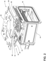
FIG. 2 is a partially exploded, side perspective view of a cooking appliance with a chimney duct assembly, according to the present disclosure; -
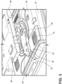
FIG. 3 is a partial partially exploded, top perspective view of a cooking appliance with a chimney duct assembly, according to the present disclosure; -
FIG. 4 is a side cross-sectional view of a chimney duct assembly disposed between a body and a cavity housing of a cooking appliance, according to the present disclosure; -
FIG. 5 is a rear perspective view of a cooking appliance with a chimney duct assembly, where a portion of an appliance body is removed, according to the present disclosure; -
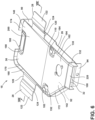
FIG. 6 is a side perspective view of a chimney duct assembly, according to the present disclosure; -
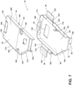
FIG. 7 is an exploded, side perspective view of a chimney duct assembly, according to the present disclosure; and -
FIG. 8 is a cross-sectional view of the chimney duct assembly ofFIG. 6 , according to the present disclosure. - The components in the figures are not necessarily to scale, emphasis instead being placed upon illustrating the principles described herein.
- The present illustrated embodiments reside primarily in combinations of method steps and apparatus components related to a chimney duct assembly. Accordingly, the apparatus components and method steps have been represented, where appropriate, by conventional symbols in the drawings, showing only those specific details that are pertinent to understanding the embodiments of the present disclosure so as not to obscure the disclosure with details that will be readily apparent to those of ordinary skill in the art having the benefit of the description herein. Further, like numerals in the description and drawings represent like elements.
- For purposes of description herein, the terms "upper," "lower," "right," "left," "rear," "front," "vertical," "horizontal," and derivatives thereof shall relate to the disclosure as oriented in
FIG. 1 . Unless stated otherwise, the term "front" shall refer to the surface of the element closer to an intended viewer, and the term "rear" shall refer to the surface of the element further from the intended viewer. However, it is to be understood that the disclosure may assume various alternative orientations, except where expressly specified to the contrary. It is also to be understood that the specific devices and processes illustrated in the attached drawings, and described in the following specification are simply exemplary embodiments of the inventive concepts defined in the appended claims. Hence, specific dimensions and other physical characteristics relating to the embodiments disclosed herein are not to be considered as limiting, unless the claims expressly state otherwise. - The terms "including," "comprises," "comprising," or any other variation thereof, are intended to cover a non-exclusive inclusion, such that a process, method, article, or apparatus that comprises a list of elements does not include only those elements but may include other elements not expressly listed or inherent to such process, method, article, or apparatus. An element preceded by "comprises a ... " does not, without more constraints, preclude the existence of additional identical elements in the process, method, article, or apparatus that comprises the element.
- Referring to
FIGS. 1-8 ,reference numeral 10 generally designates a cooking appliance. Thecooking appliance 10 includes abody 12. Acavity housing 14 is disposed in thebody 12 and defines acooking cavity 16. Achimney duct assembly 18 is disposed in aspace 20 defined between thebody 12 and thecavity housing 14. Thechimney duct assembly 18 includes achimney base 22. Aninlet 24 is defined by abottom section 26 of thechimney base 22. Abase flange 28 is coupled to thechimney base 22. The base flange 28 biases thechimney base 22 towards thecavity housing 14. Achimney top cover 30 is disposed over and operably coupled to thechimney base 22. Anoutlet 32 is defined between thechimney base 22 and thechimney top cover 30. Theinlet 24 and theoutlet 32 are in fluid communication with thecooking cavity 16 for venting. Acover flange 34 is coupled to thechimney top cover 30. The cover flange 34 biases the chimney top cover 30 towards thebody 12. - Referring to
FIG. 1-4 , thecooking appliance 10 is illustrated, which may be an oven, such as a convection oven, a steam oven, a microwave oven, and/or a conventional oven. In the illustrated example, thecooking appliance 10 is a conventional oven that includes thebody 12, such as a chassis, and thecavity housing 14 disposed within thebody 12. In additional non-limiting examples, thecooking appliance 10 may include thebody 12, thecavity housing 14 disposed within thebody 12, and aventilation plate 62 disposed between thebody 12 and thecavity housing 14. - The
oven 10 includes adoor assembly 64 that selectively closes and provides access to thecooking cavity 16 to allow for the placement and removal of items to be heated into and from thecooking cavity 16. In this respect, the illustrated configuration of thedoor assembly 64 is merely illustrative, with it being understood that various configurations of thedoor assembly 64 are possible without departing from the teachings herein. Similarly, the configuration of thebody 12 and the portions of thecooking cavity 16 not specifically discussed herein can vary according to the principles discussed herein and to accommodate the various features described in further detail herein. - The
oven 10 is also provided with acontrol panel 70, which is illustrated adjacent to thedoor assembly 64. Thecontrol panel 70 generally includes auser interface 72, which may include one or more input elements, such as push buttons, touch switches, and the like for setting operation parameters for controlling theoven 10. - Additionally, the
oven 10 is provided with a heating element for heating or cooking items, such as food stuffs, that are placed in thecooking cavity 16. The heating element, which is operable between a non-use condition and a use condition, can be configured to heat items placed in thecooking cavity 16 once thedoor assembly 64 is closed. - Referring still to
FIGS. 1-4 , as the heating element heats the inside thecooking cavity 16, the item in thecooking cavity 16 may be heated up such that moisture or vapors are emitted from the food item and accumulate within thecooking cavity 16. A blower disposed in thebody 12 may then generate an airflow that directs the vapors toward acooking cavity outlet 74. The airflow and vapors are directed through thecooking cavity outlet 74, through theinlet 24 defined on thechimney duct assembly 18, and then through theoutlet 32 of thechimney duct assembly 18 to be expelled from thecooking appliance 10. - In certain aspects where a conventional oven is configured with the heating element and the blower to expel vapors from an interior cavity, the vapors can be directed out of the interior cavity but remain in the oven. In such aspects, the vapors may translate out of the interior cavity and accumulate within a chassis but outside the interior cavity. This accumulation may occur due to a lack of an airflow path that directs air out of the oven or due to a gap between an interior cavity vent and an air duct. The gap may be such that the vapors and the airflow generated by the blower are permitted to translate through the space and around the chimney duct.
- To ensure that vapors are carried by an airflow and exhausted out of the
oven 10, thechimney duct assembly 18 disclosed herein may be installed in theoven 10 such that an airflow path is provided between thecooking cavity 16 and an ear external to theoven 10. Additionally, thechimney duct assembly 18 may self-adjust in height such that a gap between thechimney duct assembly 18 andcooking cavity outlet 74 is reduced or eliminated, directing the airflow and vapors to be exhausted out of theoven 10, as described further herein. - Referring now to
FIGS. 2-8 , thechimney duct assembly 18 is shown disposed between thebody 12 and thecavity housing 14. Thechimney duct assembly 18 is generally disposed proximate to or over thecooking cavity outlet 74 between atop section 80 of thebody 12 and atop portion 82 of thecavity housing 14. In various examples, thechimney duct assembly 18 can be disposed between theventilation plate 62 and thetop portion 82 of thecavity housing 14, such as the configuration illustrated inFIGS. 2 and3 . In such examples, theventilation plate 62 may be disposed between thecavity housing 14 and thetop section 80 of thebody 12. In additional non-limiting examples, thechimney duct assembly 18 can be disposed between thetop section 80 of thebody 12 and thetop portion 82 of thecavity housing 14. For example, thechimney duct assembly 18 can be disposed directly between thetop section 80 and thetop portion 82 and over thecooking cavity outlet 74, as illustrated inFIGS. 3 and4 . - According to various aspects, the
chimney duct assembly 18 can be coupled to thebody 12, thecavity housing 14, and/or theventilation plate 62. In some examples, thechimney duct assembly 18 can be coupled to thetop section 80 of thebody 12 and thetop portion 82 of thecavity housing 14. In other examples, thechimney duct assembly 18 can be coupled to theventilation plate 62 and thetop portion 82 of thecavity housing 14. Additionally, or alternatively, it is generally contemplated that thechimney duct assembly 18 can be disposed in various locations throughout thecooking appliance 10 and can be coupled to various locations throughout thecooking appliance 10. - According to various aspects, the
chimney duct assembly 18 is positioned such that airflow and the vapors generated within thecooking cavity 16 are directed out of thecooking cavity 16 and then exhausted out of thebody 12. In particular, thechimney duct assembly 18 can be positioned such that theinlet 24 is in fluid communication with thecooking cavity outlet 74 and theoutlet 32 of thechimney duct assembly 18 extends beyond thebody 12. For example, in the illustrated example shown inFIGS. 3-5 , theinlet 24 is disposed vertically and directly over thecooking cavity outlet 74, and theoutlet 32 extends beyond arear section 84 of thebody 12. In such examples, the vapors and airflow enter into thechimney duct assembly 18 via theinlet 24 and are then exhausted out of thechimney duct assembly 18 via theoutlet 32. - Referring again to
FIGS. 2-8 , thechimney duct assembly 18 includes thechimney base 22. Thechimney base 22 may be disposed in thespace 20 defined between thebody 12 and thecavity housing 14. In various examples, thechimney base 22 may be disposed between thetop section 80 of thebody 12 and thetop portion 82 of thecavity housing 14. According to various examples, thechimney base 22 may be coupled to thetop portion 82 of thecavity housing 14. In such examples, thechimney base 22 may be connected to thetop portion 82 via one or more fasteners. For example, one or more snap-fit fasteners or threaded fasteners may connect thechimney base 22 to thetop portion 82 of thecavity housing 14. Additionally, it is generally contemplated that thechimney base 22 may be disposed in various regions within thespace 20, so long as thechimney base 22 may be in fluid communication with thecooking cavity 16, as provided herein. - As illustrated in
FIGS. 3-8 , thechimney base 22 includes thebottom section 26 and asidewall 90 extending along an outer periphery of thebottom section 26. Thebottom section 26 of thechimney base 22 generally abuts thetop portion 82 of thecavity housing 14 and receives one or more fasteners for coupling thechimney base 22 to thetop portion 82. As illustrated inFIGS. 3-8 , thesidewall 90 extends towards thetop section 80 of thebody 12 and is generally perpendicular to thechimney base 22 such that an interior 92 is defined within thesidewall 90. - According to various aspects, the perpendicular extension of the
sidewall 90 away from thechimney base 22 is such that moisture or liquid that may accumulate within thechimney base 22 is prevented from leaking out of thechimney base 22 and subsequently thechimney duct assembly 18. This moisture or liquid can instead be kept in the interior 92 and directed out of theoutlet 32. Thesidewall 90 can be integrally formed with thebottom section 26 or a separate component coupled to thebottom section 26. Additionally, thesidewall 90 may be integrally formed with various other components of thechimney duct assembly 18, as provided herein. - Referring to
FIGS. 3 and5 , theinlet 24 may be defined on thebottom section 24 of thechimney base 22. Theinlet 24 may be defined in various regions of thebottom section 26, such as a central region or a front region of thebottom section 26. Typically, theinlet 24 is defined proximate to thecooking cavity outlet 74 to be in fluid communication with thecooking cavity outlet 74 such that air and vapors may translate or flow from thecooking cavity 16, through thecooking cavity outlet 74, and then through theinlet 24 and into thechimney duct assembly 18. It is generally contemplated that theinlet 24 may define various shapes. For example, theinlet 24 may have a rectangular or circular shape. In additional examples, theinlet 24 may define a mating shape to thecooking cavity outlet 74 to maximize airflow into thechimney duct assembly 18. It is also generally contemplated that theinlet 24 may be defined as one or more apertures. For example, theinlet 24 may be defined as a plurality of apertures that define a mesh region on thebottom section 26. It is further contemplated that additional elements, such as a mesh or filter, may be disposed proximate and/or in fluid communication with theinlet 24. - Referring to
FIGS. 3 and5-8 , thechimney base 22 includes a retainingflange 94 extending from arear section 100 of thechimney base 22. As illustrated inFIG. 5 , the retainingflange 94 may be proximate theoutlet 32 and extend downward such that the retainingflange 94 abuts therear section 84 of thebody 12. According to various aspects, the retainingflange 94 is configured to assist in coupling thechimney base 22 to thetop portion 82 of thecavity housing 14. Further, the retainingflange 94 may assist with inserting thechimney duct assembly 18 into thespace 20 to align with thecooking cavity outlet 74. - Referring to
FIGS. 2-4 and6-8 , thechimney base 22 includes thebase flange 28 extending from thesidewall 90. In various examples, thechimney base 22 may include a plurality ofbase flanges 28, which may also be referred to as upper flanges or biasing flanges. For example, in the illustrated configuration, thechimney base 22 includes a pair ofbase flanges 28 extending outward from thesidewall 90. - Referring to
FIGS. 3 and5-8 , the pair ofbase flanges 28 may be coupled to thesidewall 90 or may be integrally formed with thesidewall 90. For example, thebase flanges 28 may be integrally formed from thesidewall 90 and extend from a top edge or atop segment 110 of thesidewall 90, as illustrated inFIG. 6 . Thebase flange 28 may be constructed as a pair ofupper biasing flanges 28 that extend outward from thesidewall 90 and toward thetop section 80 of thebody 12. - According to various aspects, the
base flange 28 is configured to engage an upper surface, such as thetop section 80 of thebody 12 and/or theventilation plate 62, and provide a biasing force that biases thechimney base 22 towards thetop portion 82 of thecavity housing 14. In various examples, thebase flange 28 may generate the biasing force due to a high elasticity and yield strength of thebase flange 28. For example, thebase flange 28 may be constructed of a spring steel such that a downward force applied to thebase flange 28 results in thebase flange 28 being in a stressed condition, overcoming the biasing force and generating a downward-directed biasing force on thechimney base 22. - The configuration of the
base flanges 28 may contribute to the biasing force. For example, eachbase flange 28 may include aproximal segment 120, adistal segment 122 spaced apart from theproximal segment 120, and a steppedsegment 124 between theproximal segment 120 and thedistal segment 122. In various aspects, theproximal segment 120 can be coupled to thesidewall 90 of thechimney base 22 and extend outward from thesidewall 90. Theproximal segment 120 may be generally perpendicular to thesidewall 90. It is also generally contemplated that theproximal segment 120 may be acutely angled or obtusely angled relative to thesidewall 90. Theproximal segment 120 may be integrally formed from thesidewall 90. For example, theproximal segment 120 and thesidewall 90 may be formed from a single material or compound. - The
distal segment 122, as illustrated inFIG. 8 , is coupled to theproximal segment 120 via the steppedsegment 124. In various examples, thedistal segment 122 may be integrally formed with the steppedsegment 124 or the steppedsegment 124 and theproximal segment 120. For example, thebase flange 28 may be constructed such that thesidewall 90, theproximal segment 120, thedistal segment 122, and theproximal segment 120 are unitarily formed from a single material and form a single component. - As illustrated in
FIGS. 3-8 , thedistal segment 122 may be angled relative to theproximal segment 120. In various examples, thedistal segment 122 may be at a zero-degree angle relative to theproximal segment 120 such that thedistal segment 122 and theproximal segment 120 are generally parallel. In additional examples, thedistal segment 122 may be acutely angled or obtusely angled relative to theproximal segment 120. - According to various aspects, the
distal segment 122 may be offset from theproximal segment 120. The offset relationship between thedistal segment 122 and theproximal segment 120 is generally determined by the steppedsegment 124. In particular, the offset relationship may be determined by a length of the steppedsegment 124 and an angle of extension of the steppedsegment 124 relative to theproximal segment 120 and/or thedistal segment 122. The offset nature of thedistal segment 122 and the angledproximal segment 120 allows thebase flange 28 to engage the upper surface and bend or move to provide the biasing force on thechimney base 22. - It is generally contemplated that the biasing force generated by the
base flange 28 may be generated via a material property of theentire base flange 28 or a portion of thebase flange 28. For example, thebase flange 28 may be constructed such that theproximal segment 120 and thedistal segment 122 are substantially rigid and the steppedsegment 124 is constructed of a spring steel. In such examples, a force on thedistal segment 122 may cause the steppedsegment 124 to temporarily deform such that a biasing force is generated. It is also generally contemplated that theproximal segment 120 and/or thedistal segment 122 may be constructed such that eachsegment base flange 28 is such that alignment between thecooking cavity outlet 74 and theinlet 24 is maintained and the air-tight seal is defined between thechimney duct assembly 18 and thecavity housing 14, as provided herein. - According to various aspects, the biasing force directed on the
chimney base 22 is configured to assist in retaining a static engagement between thechimney base 22 and thetop portion 82 of thecavity housing 14. In particular, the biasing force directed on thechimney base 22 can be such that alignment between thecooking cavity outlet 74 and theinlet 24 is maintained and the engagement between thechimney duct assembly 18 and the cavity housing 1214 defines an air-tight seal and airflow is prevented from circumventing thechimney duct assembly 18 when existing thecooking cavity outlet 74. - It is generally contemplated that the
chimney base 22 may include a plurality of biasingflanges 28. For example, thechimney base 20 may include a pair of biasingflanges 32 extending outward from thesidewall 22. It is also generally contemplated that thechimney base 22 may include a plurality of biasingflanges 28 in various locations along thechimney base 22, so long as a downward-directed biasing force is directed towards thechimney base 22 and biases thechimney base 22 downward and towards thecavity housing 14. - Referring again to
FIGS. 2-8 , thechimney duct assembly 18 includes thechimney cover 30. According to various aspects, thechimney cover 30 may be constructed as a chimney top cover 30 extending over thechimney base 22. The chimney top cover 30 can be at least partially disposed in theinterior 92 of thechimney base 22 and include a coveringportion 130 that opposes and can be generally parallel with thebottom section 26 of thechimney base 22. The coveringportion 130 may operably engage or abut thetop section 80 of thebody 12 and/or theventilation plate 62. - In various examples, the distance between the chimney
top cover 30 and thechimney base 22 generally defines a total height of thechimney duct assembly 18. In various examples, the height of thechimney top cover 30 and thechimney base 22 may be determined by various factors, such as thespace 20 between thetop section 80 of thebody 12 and thetop portion 82 of thecavity housing 14, the height of awall portion 132, the height of thesidewall 90, and other various aspects, as provided herein. Moreover, the height of thechimney duct assembly 18 may be dynamic or adjustable based on various factors. - According to various aspects, the covering
portion 130 may include afront region 140 and arear region 142 proximate thefront region 140. As illustrated inFIGS. 6 and7 , thefront region 140 may be proximate afront segment 144 of thechimney base 22 and therear region 142 may be proximate therear segment 146 of thechimney base 22 and theoutlet 32. Thefront region 140 and therear region 142 may both define a shape that coincides with a shape of thechimney base 22. For example, thefront region 140 may define a rectangular shape that coincides with a rectangular shape of therear segment 146, and therear region 142 may taper towards theoutlet 32 as therear segment 146 tapers towards theoutlet 32. - Referring again to
FIGS. 7 and8 , the chimney top cover 30 generally includes thewall portion 132 that extends at least partially along an outer periphery of the coveringportion 130. In various examples, thewall portion 132 may be constructed as a wall or panel that extends away from the coveringportion 130 and toward or into the interior 92 of thechimney base 22. In various examples, thewall portion 132 may extend generally perpendicular from the coveringportion 130 such that thewall portion 132 is generally parallel with thesidewall 90. - According to various aspects, the
wall portion 132 may include afirst side section 160 and asecond side section 162 opposing thefirst side section 160. Both thefirst side section 160 and thesecond side section 162 may extend from a front end of thechimney top cover 30 and towards theoutlet 32, as illustrated inFIGS. 7 and8 . Thefirst side section 160 and thesecond side section 162 may both define a height that varies along a depth of thechimney top cover 30. For example, the height of thefirst side section 160 and thesecond side section 162 may gradually increase as bothside sections outlet 32. In such examples, the gradual increase in height can result in the coveringportion 130 being angled towards theoutlet 32 and thefront region 140 being a closer distance to thebottom section 26 than therear region 142. - Referring further to
FIGS. 6-8 , thefirst side section 160 may further include afirst segment 170 and asecond segment 172. As illustrated inFIG. 6 , thefirst segment 170 extends from afront section 174 of thechimney base 22 and towards thesecond segment 172 and is generally parallel with thesecond side section 162. Thesecond segment 172 is defined between thefirst segment 170 and theoutlet 32. In various examples, thesecond segment 172 extends towards thesecond side section 162 and/or theoutlet 32 such that the chimney top cover 30 tapers towards theoutlet 32. In such examples, thesecond segment 172 may maintain a generally parallel relationship with thesidewall 90. For example, thesidewall 90 may first extend from thefront section 174 and along thefirst segment 170, and then thesidewall 90 may extend along thesecond segment 172 and towards thesecond side section 162. This configuration may assist in guiding the airflow toward and through theoutlet 32. - The
chimney top cover 30 may be coupled to thechimney base 22 via one ormore tabs tabs sidewall 90 or be integrally formed with thesidewall 90. Eachtab FIG. 7 , eachtab chimney base 22 such that insertion of the chimney top cover 30 into the interior 92 of thechimney base 22 is permitted. - As illustrated in
FIG. 6 , thetabs tab sidewall 90 and engages with or abuts the coveringportion 130 of thechimney top cover 30. In such examples, the chimney top cover 30 can be coupled to thechimney base 22 via abutment with thefirst tab 180 that extends inward from thesidewall 90 and engages with thefront region 140 of the coveringportion 130, and abutment with thesecond tab 182 and thethird tab 184 that extends inward from thesidewall 90 and engage opposing sides of therear region 142. - In additional non-limiting examples, the
first tab 180 may engage with thefront region 140, and thesecond tab 182 and thethird tab 184 may be spaced apart from therear region 142. In such examples, thefirst tab 180 may be configured to couple the chimney top cover 30 to thechimney base 22, and thesecond tab 182 and thethird tab 184 may be configured to define a maximum height, or height threshold, of the chimney top cover 30 relative to thechimney base 22. Additionally, it is generally contemplated that thechimney duct assembly 18 may include varying numbers of tabs or various sizes, thicknesses, shapes, and placement, so long as thechimney top cover 30 may be coupled to and movable relative to thechimney base 22. - As illustrated in
FIG. 6 , thetabs regions portion 130, respectively. In such examples, the degree of recession of each recessedregion top surface 200 of thechimney top cover 30 may be such that eachtab top surface 200 of thechimney top cover 30 when abutting thechimney top cover 30. - Additionally, it is generally contemplated that each recessed
region first side section 160 and thesecond side section 162. For example, the coveringportion 130 of thechimney top cover 30 may be sloped and angled relative to thechimney base 22 due to thefirst side section 160 and thesecond side section 162 gradually increasing in height as eachsection outlet 32. To ensure that eachtab portion 130 and engages with thechimney top cover 30, the bottom surface or each recessedregion portion 130 such that a generally flat surface is provided for eachtab - Referring to
FIG. 8 , thechimney top cover 30 includes thecover flange 34 extending from thewall portion 132. In various examples, thechimney top cover 30 may include a plurality ofcover flanges 34, which may also be referred to as biasing flanges or lower flanges. For example, thechimney top cover 30 may include a pair ofcover flanges 34 extending from thewall portion 132. As illustrated inFIG. 8 , the pair ofcover flanges 34 may be coupled to thefirst side section 160 and thesecond side section 162 of thewall portion 132, or the pair ofcover flanges 34 may be integrally formed from thefirst side section 160 and thesecond side section 162, respectively. The pair ofcover flanges 34 generally extend inward toward one another. - In other examples, the
chimney top cover 30 may include asingle cover flange 34 extending along an outer periphery of the coveringportion 130. For example, thesingle cover flange 34 may continuously extend from awall portion 132 that is defined as a single section that begins at a side of theoutlet 32, extends around the outer periphery of the coveringportion 130, and ends at an opposing side of theoutlet 32. - According to various aspects, the
cover flange 34 is configured to abut thebottom section 26 of thechimney base 22 and provides a biasing force that biases or directs the chimney top cover 30 away from thechimney base 22 and towards thetop section 80 of thebody 12. In various examples, the biasing force may be configured to direct the chimney top cover 30 upward until thechimney top cover 30 abuts thetop section 80 of thebody 12 and/or thesecond tab 182 and thethird tab 184. In such examples, the distance between the chimneytop cover 30 and thechimney base 22, or the total height of thechimney duct assembly 18, may be at least partially determined by the degree of biasing provided by thecover flange 34, thespace 20 between thetop section 80 of thebody 12 and thetop portion 82 of thecavity housing 14, thespace 20 between theventilation plate 62 and thetop portion 82, or by the placement of thetabs - In various examples, the
cover flange 34 may generate the biasing force due to one or more material properties of thecover flange 34. For example, thecover flange 34 may have a high elasticity and yield strength that results in thecover flange 34 having a high spring tension. In such examples, thecover flange 34 may be constructed of a spring steel such that a downward force applied in thecover flange 34 results in an upward-directed biasing force on thechimney top cover 30. It is also generally contemplated that thechimney top cover 30 may include a plurality oflower biasing flanges 34 in various locations, so long as a biasing force directed upward is generated when a downward force is applied to thechimney top cover 30. - As illustrated in
FIG. 8 , similar to thebase flange 28, the configuration of thecover flange 34 may contribute to the biasing force. Thecover flange 34 may include aproximal portion 210 and adistal portion 212 extending from theproximal portion 210. In various examples, theproximal portion 210 may extend inward from thewall portion 132 of thechimney top cover 30. In such examples, theproximal portion 210 may be coupled to or integrally formed with thefirst side section 160 and/or thesecond side section 162 of thewall portion 132. Further, in such examples, theproximal portion 210 can extend at an angle relative to thefirst side section 160 and/or thesecond side section 162. For example, aproximal portion 210 extending from thefirst side section 160 and aproximal portion 210 extending from thesecond side section 162 may both extend toward thebottom section 26 of thechimney base 22. - According to various aspects, the angled and inward extension of the
proximal portion 210 can provide a joint in which thecover flange 34 may flex when a compression force is applied to thechimney top cover 30. In such examples, the angled and inward extension of theproximal portion 210 can likewise permit flexing of thecover flange 34 while maintaining rigidity in thewall portion 132. In additional aspects, the angled and inward extension of theproximal portion 210 can serve to aid in the insertion of the chimney top cover 30 into the interior 92 of thechimney base 22. In particular, theproximal portion 210 may contact thesidewalls 90 during insertion and the angled extension of thesidewalls 90 may guide the chimney top cover 30 into the interior 92. Additionally, the angled and inward extension of theproximal portion 210 can serve to direct moisture that may accumulate towards thebottom section 26 of thechimney base 22 and out of theoutlet 32. - The
distal portion 212, as illustrated inFIG. 8 , is coupled to and extends from theproximal portion 210. In various examples, thedistal portion 212 may be constructed such that theproximal portion 210 and thedistal portion 212 are formed from a single material and form a single component. As illustrated inFIG. 8 , thedistal portion 212 extends inward from theproximal portion 210 and can be acutely or obtusely angled relative to theproximal portion 210. In other examples, thedistal portion 212 may extend inward from thewall portion 132 and be generally parallel with thebottom section 26 of thechimney base 22. For example, thecover flange 34 may be constructed such that theproximal portion 210 angularly extends inward from thewall portion 132 and towards thebottom section 26 and thedistal portion 212 then extends inwardly and angled from theproximal portion 210. The angle of extension of thedistal portion 212, in such examples, may then be obtusely angled relative to theproximal portion 210 and generally parallel with thebottom section 26. - According to various aspects, the
distal portion 212 abuts thebottom section 26 of thechimney base 22. In particular, thedistal portion 212 abuts and biases against thebottom section 26 such that an upward-directed biasing force is generated. In some examples, the contact between thedistal portion 212 and thebottom section 26 is such that a seal is defined that prevents airflow and vapors from traveling around thedistal portion 212, and out of thechimney top cover 30. - According to various aspects, the biasing force generated by the
cover flange 34 may be generated via a material property of theentire cover flange 34 or a portion of thecover flange 34. For example, thecover flange 34 may be constructed such that theproximal portion 210 is constructed of a spring steel and thedistal portion 212 is substantially rigid. In such examples, contact between thedistal portion 212 and thebottom section 26 generates a force on thedistal portion 212. The force may cause theproximal portion 210 to temporarily deform such that the biasing force is generated. - It is also generally contemplated that the
proximal portion 210 and/or thedistal portion 212 may be constructed such that eachportion cover flange 34 may have a spring tension and provide a biasing force that is generally equal or unequal to the spring tension and biasing force provided by thebase flange 28. For example, thechimney duct assembly 18 may be constructed such that thebase flange 28 has a greater spring tension than thecover flange 34. For example, thechimney base 22 can be constructed such that thebase flange 28 and thetabs sidewall 90 and share a consistent elasticity and yield strength. Thecover flange 34 may then have a lesser spring tension to ensure the biasing force generated by thecover flange 34 does not overcome the retaining force provided by thetabs base flanges 22 on opposing sections of thesidewall 90 may be aligned with one another and thecover flanges 34 on opposingside sections chimney duct assembly 18. - Referring again to
FIGS. 6 and7 , thechimney top cover 30 may include anexhaust cover 220 connected to therear region 142. Theexhaust cover 220 can extend outward from therear region 142 and be integrally formed with the coveringportion 130 of thechimney top cover 30. As illustrated inFIG. 6 , theexhaust cover 220 may at least partially form or extend along the periphery of theoutlet 32, as illustrated inFIG. 6 . According to various aspects, theexhaust cover 220 is configured to assist in directing air and vapors out of theoven 10. - The
outlet 32 is defined at an intersection between thechimney base 22 and thechimney top cover 30. Theoutlet 32 can be defined at an end of therear region 142 of thechimney top cover 30 and therear section 100 of thechimney base 22. In particular, theoutlet 32 may be defined between the retainingflange 94 and theexhaust cover 220, as illustrated inFIG. 6 . According to various aspects, theoutlet 32 is a venting outlet that is in fluid communication with thecooking cavity outlet 74 and theinlet 24 such that airflow and vapors may flow from thecooking cavity 16, through thecooking cavity outlet 74, through theinlet 24, and through theoutlet 32. Theoutlet 32 is then configured to permit transmission of the airflow and vapors through theoutlet 32 such that the airflow and vapors are exhausted into an environment surrounding theoven 10. Additionally, or alternatively, it is generally contemplated that theoutlet 32 may define various sizes and shapes, and may be defined in various locations throughout thechimney duct assembly 18, so long as theoutlet 32 permits exhaustion of air and vapors out of theoven 10. - Referring to
FIGS. 1-8 , thechimney duct assembly 18 provides thecooking appliance 10 with an exhaust system that can readily assemble and self-adjust in height. This efficiency of assembly and self-adjustment of thechimney duct assembly 18 further permits the implementation of thechimney duct assembly 18 into various forms ofovens 10 of various sizes. - In particular, the use of the
chimney base 22 and the chimney top cover 30 in assembling thechimney duct assembly 18 permit an efficient assembly process during manufacturing. By way of example, thechimney duct assembly 18 can be assembled by first disposing thechimney base 22 in thespace 20 between thetop section 80 of thebody 12 and thetop portion 82 of thecavity housing 14 and aligning theinlet 24 over thecooking cavity outlet 74. One ormore base flanges 28 can then be bent upward and coupled to thetop section 80 of thebody 12. As thebase flanges 28 are bent upward and coupled to thetop section 80, thebase flanges 28 are placed in the stressed state, which then generates the biasing force that acts upon thechimney base 22 and assists in keeping thechimney base 22 engaged with thetop portion 82 and aligned with thecooking cavity outlet 74. The retainingflange 94 may also be coupled to therear section 84 of thebody 12 via one or more fasteners. - The
chimney top cover 30 may be inserted into the interior 92 defined by thesidewall 90. As thechimney top cover 30 is inserted into thechimney base 22, thechimney top cover 30 may be compressed such that thecover flanges 34 contact thebottom section 26 of thechimney base 22, and thecover flanges 34 bend and are in the stressed state. One or more of thetabs portion 130 of thechimney top cover 30. The stressed state of thecover flanges 34 results in an opposing biasing force that directs the chimney top cover 30 upward until the coveringportion 130 abuts one or more of thetabs ventilation plate 62, or thetop section 80 of thebody 12. - Furthermore, the spring tension and biasing force provided by the
base flange 28 and thecover flange 34 permit self-adjustment in height between thechimney base 22 and thechimney top cover 30. The self-adjustment in height of thechimney duct assembly 18 further provides for greater variance in the implementation of thechimney duct assembly 18 to various devices and in greater variance in tolerances and tolerance stacking of various components of theoven 10. For example, thechimney duct assembly 18 may be disposed in either a first oven where thetop section 80 of thebody 12 and thetop portion 18 of thecavity housing 14 are a lesser distance from one another, or a second oven where thetop section 80 and thetop portion 18 are a greater distance from one another. In either oven, the biasing force produced by thebase flange 28 and thecover flange 34 is such that thechimney base 22 engages both thetop section 80 and thetop portion 18 and thechimney top cover 30 will be biased away from thechimney base 22. - The
base flange 28, thecover flange 34, and the generated biasing forces also provide air-tight interfaces that prevent fluid leaks. In particular, the downward-directed biasing force generated by thebase flange 28 onto thechimney base 22 provides an air-tight seal between theinlet 24 and thecooking cavity outlet 74 such that airflow and vapors may not escape around thechimney duct assembly 18. The interaction between thecover flange 34 and thebottom section 26 of thechimney base 22 likewise defines an air-tight seal between thedistal portion 212 and thebottom section 26 that minimizes or prevents airflow and vapors from escaping around thecover flange 34 and out of thechimney top cover 30. Additionally, the inward and angled extension of thecover flange 34 provides a structure that guides any built-up condensation that may occur towards thebottom section 26 and out of theoutlet 32. - The use of the presently disclosed device may provide for a variety of advantages. For example, the efficient assembly of the
chimney duct assembly 18 allows for rapid installation of thechimney duct assembly 18 into acooking appliance 10. In particular, the use of thechimney base 22 with one ormore base flanges 28 andtabs more cover flanges 34 into thechimney base 22 provides for an efficient installation in different oven configurations. Additionally, the presently disclosed device provides for other advantages in manufacturing. For example, the implementation of the biasingbase flange 28 andcover flange 34 allows for self-adjustment in height of thechimney duct assembly 18. In particular, the biasingbase flange 28 provides the biasing force that directs thechimney base 22 towards thecavity housing 14, while the biasingcover flange 34 provides the biasing force that directs the chimney top cover 30 upwards and against thetabs ventilation plate 62, and/or thetop section 80 of thebody 12. The biasing forces provided by bothflanges chimney base 22 and thechimney top cover 30 will be operably disposed at the farthest possible points from each other 22, 30 in thespace 20 provided. Further, the self-adjustment in height provided by thechimney duct assembly 18 advantageously allows for greater variation in thespace 20 defined between thebody 12 and thecavity housing 14. This greater variation inspace 20 in turn allows for the implementation of thechimney duct assembly 18 into various forms of ovens and for greater variance in tolerance and in tolerance stacking of the various forms of ovens. - Once assembly is completed, the use of the presently disclosed device may provide for various other advantages. For example, the use of the
chimney base 22 with thesidewall 90 that extends upward from thechimney base 22 and encompasses thewall portion 132 of thechimney top cover 30 provides for a structure that minimizes or prevents condensation and liquids from leaking out of thechimney duct assembly 18. Additionally, the biasing forces generated by thebase flange 28 and thecover flange 34 provide for an air-tight seal between thecooking cavity outlet 74 and theinlet 24, and an air-tight seal between thebottom section 26 of thechimney base 22 and thedistal portion 212 of thecover flange 34. Additional benefits or advantages of using this device may also be realized or achieved. - The device disclosed herein is further summarized in the following paragraphs and is further characterized by combinations of any and all of the various aspects described therein.
- According to one aspect of the present disclosure, a cooking appliance includes a body and a cavity housing disposed in the body. The cavity housing defines a cooking cavity. A self-adjusting chimney duct assembly is disposed in a space defined between the body and the cavity housing. The chimney duct assembly includes a chimney base. An inlet is defined on a bottom section of the chimney base. A base flange is coupled to the chimney base. The base flange biases the chimney base towards the cavity housing. A chimney top cover is disposed over and operably coupled to the chimney base. An outlet is defined between the chimney base and the chimney top cover. The inlet and the outlet are in fluid communication with the cooking cavity for venting. A cover flange is coupled to the chimney top cover. The cover flange biases the chimney top cover towards the body.
- According to another aspect of the present disclosure, a base flange and a cover flange are spring tensioned to bias a chimney base and a chimney top cover in opposing directions to adjust to a height of a space between a body and a cavity housing.
- According to another aspect of the present disclosure, a base flange operably engages with a body and has a greater spring tension than a cover flange.
- According to another aspect of the present disclosure, a chimney base includes a sidewall. A base flange defines a proximal segment extending from the sidewall, a distal segment apart from the proximal segment, and a stepped segment defined between the proximal segment and the distal segment. The distal segment abuts a top section of a body.
- According to another aspect of the present disclosure, the chimney top cover includes a covering portion and a wall portion disposed along an outer periphery of the covering portion and perpendicular to the covering portion. A cover flange defines a proximal portion extending inward from the wall portion and a distal portion adjacent the proximal portion. The proximal portion is angled relative to a bottom section of a chimney base and the distal portion abuts the bottom section.
- According to another aspect of the present disclosure, a sidewall at least partially encompasses an outer periphery of a wall portion.
- According to another aspect of the present disclosure, a cover flange defines a proximal portion and a distal portion. The proximal portion is angled toward a bottom section of a chimney base and the distal portion abuts the bottom section to bias a chimney top cover away from the chimney base.
- According to another aspect of the present disclosure, a self-adjusting chimney duct assembly further includes a retaining flange extending outward from a chimney base and is coupled to a cavity housing.
- According to another aspect of the present disclosure, a chimney base includes a sidewall that extends along an outer periphery of the bottom section of the chimney base, and a self-adjusting chimney duct assembly further includes a first tab and a second tab extending inward from the sidewall. The first tab and the second tab are coupled to opposing sections of the sidewall, respectively and the first tab and the second tab abut the chimney top cover.
- According to another aspect of the present disclosure, a self-adjusting chimney duct assembly further includes a third tab coupled to a sidewall and extending inward from the sidewall. The third tab extends perpendicular to a first tab and a second tab and the third tab abuts a chimney top cover.
- According to another aspect of the present disclosure, a ventilation plate is disposed between a body and a cavity housing and a base flange engages with the ventilation plate and biases a chimney base towards the cavity housing.
- According to another aspect of the present disclosure, a cooking appliance ventilation system includes a body having a top section. A cavity housing is disposed within the body and has a top portion. A space is defined between the top portion of the cavity housing and the top section of the body. A chimney duct assembly is disposed in the space between the cavity housing and the body. The chimney duct assembly includes a chimney base having a sidewall that defines an interior. The chimney base defines an inlet on a bottom section. A first pair of biasing flanges are coupled to the chimney base and extend outward from the sidewall. The first pair of biasing flanges operably engage with the body and bias the chimney base towards the cavity housing. A chimney top cover is disposed over and operably coupled to the chimney base. The chimney top cover has a covering portion and a wall portion. An outlet is defined between the chimney base and the chimney top cover. The outlet is in fluid communication with the inlet. A second pair of biasing flanges are coupled to the wall portion and extend inward from the wall portion. The second pair of biasing flanges bias the chimney top cover towards the body and away from the chimney base to adjust to a height of the space between the cavity housing and the body.
- According to another aspect of the present disclosure, a first pair of biasing flanges have a greater biasing force than a second pair of biasing flanges.
- According to another aspect of the present disclosure, a first pair of biasing flanges each defines a proximal segment extending from a sidewall and a distal segment spaced apart from the proximal segment by a stepped segment. A second pair of biasing flanges each defines a proximal portion extending inward from a wall portion and a distal portion spaced apart from the wall portion by the proximal portion. The distal portion abuts a bottom section.
- According to another aspect of the present disclosure, a wall portion includes a first side section and a second side section opposing the first side section.
- According to another aspect of the present disclosure, a first side section includes a first segment and a second segment extending towards a second side section to define an outlet.
- According to yet another aspect of the present disclosure, a ventilation system for a cooking appliance includes a body with a top section. A cavity housing is disposed within the body. The cavity housing has a top portion and defines a cooking cavity. A chimney duct assembly is disposed between the cavity housing and the body. The chimney duct assembly includes a chimney base with a sidewall extending from a bottom section. An inlet is defined by the bottom section and is configured to align with a cooking cavity outlet defined by the cavity housing to permit an airflow from the cooking cavity. The chimney base includes upper biasing flanges extending outward from the sidewall. The upper biasing flanges operably engage with the top section and bias the chimney base towards the cavity housing. A chimney cover is disposed over and operably coupled to the chimney base. The chimney cover includes a covering portion and a wall portion extending from the covering portion. The chimney cover includes lower biasing flanges extending inward from the wall portion. The lower biasing flanges bias the chimney cover towards the top section. A venting outlet is defined between the chimney base and the chimney cover. The venting outlet is in fluid communication with the cooking cavity outlet and the inlet for venting the cooking cavity.
- According to another aspect of the present disclosure, a chimney duct assembly further includes a pair of tabs extending inward from a sidewall. The pair of tabs are coupled to opposing sections of the sidewall, respectively and abut a chimney cover and define a maximum height of a chimney duct assembly.
- According to another aspect of the present disclosure, a chimney duct assembly further includes a retaining flange that extends outward from a chimney base and is coupled to a cavity housing.
- According to another aspect of the present disclosure, a wall portion of the chimney top cover extends from a front section of a chimney base to a venting outlet. The wall portion increases in height as the wall portion extends towards the venting outlet to adjust a height between a cavity housing and a body.
- According to a 1st aspect, a cooking appliance includes a body and a cavity housing disposed in the body. The cavity housing defines a cooking cavity. A self-adjusting chimney duct assembly is disposed in a space defined between the body and the cavity housing. The chimney duct assembly includes a chimney base. An inlet is defined on a bottom section of the chimney base. A base flange is coupled to the chimney base. The base flange biases the chimney base towards the cavity housing. A chimney top cover is disposed over and operably coupled to the chimney base. An outlet is defined between the chimney base and the chimney top cover. The inlet and the outlet are in fluid communication with the cooking cavity for venting. A cover flange is coupled to the chimney top cover. The cover flange biases the chimney top cover towards the body.
- In a 2nd aspect according to aspect 1, the base flange and the cover flange are spring tensioned to bias the chimney base and the chimney top cover in opposing directions to adjust to a height of the space between the body and the cavity housing.
- In a 3rd aspect according to aspect 1 or 2, the base flange operably engages with the body and has a greater spring tension than the cover flange.
- In a 4th aspect according to any of aspects 1 to 3, the chimney base includes a sidewall.
- In a 5th aspect according to aspect 4, the base flange defines a proximal segment extending from the sidewall, a distal segment spaced apart from the proximal segment, and a stepped segment defined between the proximal segment and the distal segment.
- In a 6th aspect according to aspect 5, the distal segment abuts a top section of the body.
- In a 7th aspect according to any of aspects 1 to 6, the chimney top cover includes a covering portion and a wall portion disposed along an outer periphery of the covering portion and perpendicular to the covering portion.
- In an 8th aspect according to aspect 7, the cover flange defines a proximal portion extending inward from the wall portion and a distal portion adjacent the proximal portion.
- In a 9th aspect according to aspect 8, the proximal portion is angled toward the bottom section of the chimney base and the distal portion abuts the bottom section to bias the chimney top cover away from the chimney base.
- In a 10th aspect according to aspect 7, 8 or 9 when aspect 7 is according to aspect 4, 5 or 6, the sidewall at least partially encompasses an outer periphery of the wall portion.
- In an 11th aspect according to any of aspects 7 to 10, the wall portion includes a first side section and a second side section opposing the first side section.
- In a 12th aspect according to aspect 11, the first side section includes a first segment and a second segment.
- In a 13th aspect according to
aspect 12, the second segment extends towards the second side section to define the venting outlet. - In a 14th aspect according to any of aspects 7 to 13, the wall portion of the chimney top cover extends from a front section of the chimney base to the venting outlet.
- In a 15th aspect according to
aspect 14, the wall portion increases in height as the wall portion extends towards the venting outlet to adjust to a height between the cavity housing and the body. - In a 16th aspect according to aspect 4, 5 or 6 or according to any of aspects 7 to 15 when aspect 7 is according to any of aspects 4 to 6, the sidewall extends along an outer periphery of the bottom section of the chimney base.
- In a 17th aspect according to
aspect 16, the self-adjusting chimney duct assembly further includes: a first tab and a second tab extending inward from the sidewall. - In a 18th aspect according to aspect 17, the first tab and the second tab are coupled to opposing sections of the sidewall, respectively.
- In a 19th aspect according to
aspect 17 or 18, the first tab and the second tab abut the chimney top cover. - In a 20th aspect according to
aspect 17, 18 or 19, the self-adjusting chimney duct assembly further includes: a third tab coupled to the sidewall and extending inward from the sidewall. - In a 21st aspect according to
aspect 20, the third tab extends perpendicular to the first tab and the second tab. - In a 22nd aspect according to
aspect 20 or 21, the third tab abuts the chimney top cover. - In a 23rd aspect according to any of aspects 1 to 22, the inlet defined by the bottom section is configured to align with a cooking cavity outlet defined by the cavity housing to permit an airflow from the cooking cavity.
- In a 24th aspect according to aspect 23, the venting outlet is in fluid communication with the cooking cavity outlet and the inlet for venting the cooking cavity.
- In a 25th aspect according to any of aspects 1 to 24, the self-adjusting chimney duct assembly further includes: a retaining flange extending outward from the chimney base and coupled to the cavity housing.
- In a 26th aspect according to any of aspects 1 to 25, further comprising: a ventilation plate disposed between the body and the cavity housing.
- In a 27th aspect according to
aspect 26, the base flange engages with the ventilation plate and biases the chimney base towards the cavity housing. - For purposes of this disclosure, the term "coupled" (in all of its forms, couple, coupling, coupled, etc.) generally means the joining of two components (electrical or mechanical) directly or indirectly to one another. Such joining may be stationary in nature or movable in nature. Such joining may be achieved with the two components (electrical or mechanical) and any additional intermediate members being integrally formed as a single unitary body with one another or with the two components. Such joining may be permanent in nature or may be removable or releasable in nature unless otherwise stated.
Claims (15)
- A cooking appliance (10), comprising:a body (12);a cavity housing (14) disposed in the body (12), the cavity housing (14) defining a cooking cavity (16); anda self-adjusting chimney duct assembly (18) disposed in a space (20) defined between the body (12) and the cavity housing (14), the chimney duct assembly (18) comprising:a chimney base (22), wherein an inlet (24) is defined on a bottom section (26) of the chimney base (22);a base flange (28) coupled to the chimney base (22), the base flange (28) biasing the chimney base (22) towards the cavity housing (14);a chimney top cover (30) disposed over and operably coupled to the chimney base (22), wherein a venting outlet (32) is defined between the chimney base (22) and the chimney top cover (30), and wherein the inlet (24) and the venting outlet (32) are in fluid communication with the cooking cavity (16) for venting; anda cover flange (34) coupled to the chimney top cover (30), the cover flange (34) biasing the chimney top cover (30) towards the body (12).
- The cooking appliance (10) of claim 1, wherein the base flange (28) and the cover flange (34) are spring tensioned to bias the chimney base (22) and the chimney top cover (30) in opposing directions to adjust to a height of the space (20) between the body (12) and the cavity housing (14).
- The cooking appliance (10) of claim 1 or 2, wherein the base flange (28) operably engages with the body (12) and has a greater spring tension than the cover flange (34).
- The cooking appliance (10) of any one of claims 1-3, wherein the chimney base (22) includes a sidewall (90), and wherein the base flange (28) defines a proximal segment (120) extending from the sidewall (90), a distal segment (122) spaced apart from the proximal segment (120), and a stepped segment (124) defined between the proximal segment (120) and the distal segment (122), and further wherein the distal segment (122) abuts a top section (80) of the body (12).
- The cooking appliance (10) of claim 4, wherein the chimney top cover (30) includes a covering portion (130) and a wall portion (132) disposed along an outer periphery of the covering portion (130) and perpendicular to the covering portion (130), and wherein the cover flange (34) defines a proximal portion (210) extending inward from the wall portion (132) and a distal portion (212) adjacent the proximal portion (210).
- The cooking appliance (10) of claim 5, wherein the proximal portion (210) is angled toward the bottom section (26) of the chimney base (22) and the distal portion (212) abuts the bottom section (26) to bias the chimney top cover (30) away from the chimney base (22).
- The cooking appliance (10) of either one of claims 5 or 6, wherein the sidewall (90) at least partially encompasses an outer periphery of the wall portion (132).
- The cooking appliance (10) of any one of claims 5-7, wherein the wall portion (132) includes a first side section (160) and a second side section (162) opposing the first side section (160), and wherein the first side section (160) includes a first segment (170) and a second segment (172), the second segment (172) extending towards the second side section (162) to define the venting outlet (32).
- The cooking appliance (10) of any one of claims 5-8, wherein the wall portion (132) of the chimney top cover (30) extends from a front section (174) of the chimney base (22) to the venting outlet (32), and wherein the wall portion (132) increases in height as the wall portion (132) extends towards the venting outlet (32) to adjust to a height between the cavity housing (14) and the body (12).
- The cooking appliance (10) of any one of claims 4-9, wherein the sidewall (90) extends along an outer periphery of the bottom section (26) of the chimney base (22), and wherein the self-adjusting chimney duct assembly (18) further includes:
a first tab (180) and a second tab (182) extending inward from the sidewall (90), wherein the first tab (180) and the second tab (182) are coupled to opposing sections of the sidewall (90), respectively, and wherein the first tab (180) and the second tab (182) abut the chimney top cover (30). - The cooking appliance (10) of claim 10, wherein the self-adjusting chimney duct assembly (18) further includes:
a third tab (184) coupled to the sidewall (90) and extending inward from the sidewall (90), wherein the third tab (184) extends perpendicular to the first tab (180) and the second tab (182), and wherein the third tab (184) abuts the chimney top cover (30). - The cooking appliance (10) of any one of claims 1-11, wherein the inlet (24) defined by the bottom section (26) is configured to align with a cooking cavity outlet (74) defined by the cavity housing (14) to permit an airflow from the cooking cavity (16).
- The cooking appliance (10) of claim 12, wherein the venting outlet (32) is in fluid communication with the cooking cavity outlet (74) and the inlet (24) for venting the cooking cavity (16).
- The cooking appliance (10) of any one of claims 1-13, wherein the self-adjusting chimney duct assembly (18) further includes:
a retaining flange (94) extending outward from the chimney base (22) and coupled to the cavity housing (14). - The cooking appliance (10) of any one of claims 1-14, further comprising:
a ventilation plate (62) disposed between the body (12) and the cavity housing (14), wherein the base flange (28) engages with the ventilation plate (62) and biases the chimney base (22) towards the cavity housing (14).
Applications Claiming Priority (1)
| Application Number | Priority Date | Filing Date | Title |
|---|---|---|---|
| US18/124,803 US20240318832A1 (en) | 2023-03-22 | 2023-03-22 | Adaptive chimney duct |
Publications (1)
| Publication Number | Publication Date |
|---|---|
| EP4435330A1 true EP4435330A1 (en) | 2024-09-25 |
Family
ID=90368788
Family Applications (1)
| Application Number | Title | Priority Date | Filing Date |
|---|---|---|---|
| EP24164575.3A Withdrawn EP4435330A1 (en) | 2023-03-22 | 2024-03-19 | Adaptive chimney duct |
Country Status (2)
| Country | Link |
|---|---|
| US (1) | US20240318832A1 (en) |
| EP (1) | EP4435330A1 (en) |
Citations (4)
| Publication number | Priority date | Publication date | Assignee | Title |
|---|---|---|---|---|
| US7468496B2 (en) * | 2006-11-15 | 2008-12-23 | Electrolux Home Products, Inc. | Dynamic flow oven cavity vent |
| DE10202132B4 (en) * | 2002-01-21 | 2011-07-14 | BSH Bosch und Siemens Hausgeräte GmbH, 81739 | Oven with a steam channel |
| WO2018024561A1 (en) * | 2016-08-03 | 2018-02-08 | Arcelik Anonim Sirketi | Oven with improved ventilation and improved vapor extraction |
| CN112240585A (en) * | 2020-09-30 | 2021-01-19 | 宁波方太厨具有限公司 | High-efficient exhaust cooking equipment |
Family Cites Families (5)
| Publication number | Priority date | Publication date | Assignee | Title |
|---|---|---|---|---|
| US7586058B2 (en) * | 2007-04-27 | 2009-09-08 | Eaton Corporation | Electrical switching apparatus, and ARC hood assembly and chimney therefor |
| EP2372254B1 (en) * | 2010-03-30 | 2019-06-26 | Electrolux Home Products Corporation N.V. | Range comprising a housing wall and an assembly for mounting a venting duct in said housing wall |
| KR101732164B1 (en) * | 2010-12-27 | 2017-05-04 | 동부대우전자 주식회사 | Microwave having air blower |
| EP3029382B1 (en) * | 2014-12-01 | 2018-11-28 | Electrolux Appliances Aktiebolag | Kitchen appliance comprising a humidity flushing system |
| US10830454B2 (en) * | 2018-05-31 | 2020-11-10 | Haier Us Appliance Solutions, Inc. | Ventilation systems having reconfigurable airflow features |
-
2023
- 2023-03-22 US US18/124,803 patent/US20240318832A1/en active Pending
-
2024
- 2024-03-19 EP EP24164575.3A patent/EP4435330A1/en not_active Withdrawn
Patent Citations (4)
| Publication number | Priority date | Publication date | Assignee | Title |
|---|---|---|---|---|
| DE10202132B4 (en) * | 2002-01-21 | 2011-07-14 | BSH Bosch und Siemens Hausgeräte GmbH, 81739 | Oven with a steam channel |
| US7468496B2 (en) * | 2006-11-15 | 2008-12-23 | Electrolux Home Products, Inc. | Dynamic flow oven cavity vent |
| WO2018024561A1 (en) * | 2016-08-03 | 2018-02-08 | Arcelik Anonim Sirketi | Oven with improved ventilation and improved vapor extraction |
| CN112240585A (en) * | 2020-09-30 | 2021-01-19 | 宁波方太厨具有限公司 | High-efficient exhaust cooking equipment |
Also Published As
| Publication number | Publication date |
|---|---|
| US20240318832A1 (en) | 2024-09-26 |
Similar Documents
| Publication | Publication Date | Title |
|---|---|---|
| US9012815B2 (en) | Drawer unit for oven and oven having same | |
| US20130025581A1 (en) | Exhaust baffle for kitchen appliance | |
| CN106482171A (en) | Device for cooking with sealing gasket | |
| US10578311B2 (en) | Home cooking appliance having a metered exhaust channel | |
| US20240318832A1 (en) | Adaptive chimney duct | |
| US6852963B2 (en) | Wall-mounted type microwave oven | |
| US20130019852A1 (en) | Oven | |
| EP4171174B1 (en) | High efficiency oven cavity ventilation systems and methods | |
| US20220390120A1 (en) | Cooking apparatus | |
| US9857085B2 (en) | Home appliance having a side shield | |
| CN1230663A (en) | Microwave oven having guide member for discharging gas | |
| US11428417B2 (en) | Home cooking appliance having a cooling fan air guide | |
| KR20190037993A (en) | Cooking apparatus | |
| JP5433353B2 (en) | Cooker | |
| WO2023081964A1 (en) | Venting assembly for a cooktop | |
| US20110067684A1 (en) | Cooker | |
| CN219494200U (en) | Smoke unit assembly and integrated kitchen | |
| EP4390236A1 (en) | Extraction device | |
| EP1680624B1 (en) | A microwave oven and an upper duct structure thereof | |
| US20250257879A1 (en) | Cooking appliance | |
| EP1680623B1 (en) | A microwave oven and a base cover thereof | |
| JP2013257071A (en) | Heating cooker | |
| US12193132B2 (en) | Cooking appliance | |
| KR102940666B1 (en) | Cooking apparatus | |
| US20250224121A1 (en) | Cooking apparatus |
Legal Events
| Date | Code | Title | Description |
|---|---|---|---|
| PUAI | Public reference made under article 153(3) epc to a published international application that has entered the european phase |
Free format text: ORIGINAL CODE: 0009012 |
|
| STAA | Information on the status of an ep patent application or granted ep patent |
Free format text: STATUS: THE APPLICATION HAS BEEN PUBLISHED |
|
| AK | Designated contracting states |
Kind code of ref document: A1 Designated state(s): AL AT BE BG CH CY CZ DE DK EE ES FI FR GB GR HR HU IE IS IT LI LT LU LV MC ME MK MT NL NO PL PT RO RS SE SI SK SM TR |
|
| STAA | Information on the status of an ep patent application or granted ep patent |
Free format text: STATUS: THE APPLICATION IS DEEMED TO BE WITHDRAWN |
|
| 18D | Application deemed to be withdrawn |
Effective date: 20250326 |