EP1680623B1 - A microwave oven and a base cover thereof - Google Patents
A microwave oven and a base cover thereof Download PDFInfo
- Publication number
- EP1680623B1 EP1680623B1 EP04793484.9A EP04793484A EP1680623B1 EP 1680623 B1 EP1680623 B1 EP 1680623B1 EP 04793484 A EP04793484 A EP 04793484A EP 1680623 B1 EP1680623 B1 EP 1680623B1
- Authority
- EP
- European Patent Office
- Prior art keywords
- cavity
- microwave oven
- stepped portion
- intake hole
- base cover
- Prior art date
- Legal status (The legal status is an assumption and is not a legal conclusion. Google has not performed a legal analysis and makes no representation as to the accuracy of the status listed.)
- Expired - Fee Related
Links
Images

Classifications
-
- F—MECHANICAL ENGINEERING; LIGHTING; HEATING; WEAPONS; BLASTING
- F24—HEATING; RANGES; VENTILATING
- F24C—DOMESTIC STOVES OR RANGES ; DETAILS OF DOMESTIC STOVES OR RANGES, OF GENERAL APPLICATION
- F24C15/00—Details
- F24C15/08—Foundations or supports plates; Legs or pillars; Casings; Wheels
-
- H—ELECTRICITY
- H05—ELECTRIC TECHNIQUES NOT OTHERWISE PROVIDED FOR
- H05B—ELECTRIC HEATING; ELECTRIC LIGHT SOURCES NOT OTHERWISE PROVIDED FOR; CIRCUIT ARRANGEMENTS FOR ELECTRIC LIGHT SOURCES, IN GENERAL
- H05B6/00—Heating by electric, magnetic or electromagnetic fields
- H05B6/64—Heating using microwaves
- H05B6/642—Cooling of the microwave components and related air circulation systems
Definitions
- the present invention is related to a microwave oven and base cover of the microwave oven, and more particularly, to a microwave oven and base cover of the microwave oven, in which structure of a base cover is improved to have an enhanced strength.
- a microwave oven is a device that is used to heat food by radiating microwave generated from a magnetron to the food when electric current is applied to electric components of the device.
- Such a microwave oven is classified into a household microwave oven having a small magnetron and a commercial microwave oven having a large (or a plurality of) magnetron.
- the microwave oven is further classified according to a heating method into a glass tray method rotating the food and a stirrer fan method scattering microwave radiated into the cavity.
- the former is generally applied to the household microwave oven while the latter is applied to the commercial microwave oven.
- the microwave oven Since the commercial microwave oven is generally used at convenience stores where the microwave oven is frequently used and restaurants where a large amount of the food should be quickly heated, the microwave oven needs relatively high power output compared with the household microwave oven.
- a conventional microwave oven includes an outer case forming the exterior of the microwave oven, a cavity formed in the outer case to load food therein, a magnetron installed at one side of the cavity to generate a microwave, an electric component chamber accommodating various kinds of electric components such as a transformer, and a door for opening and closing an opening of the cavity.
- the outer case includes an upper cover, a side cover, and a base cover to cover the top, side, and bottom of the cavity, respectively.
- the upper cover is spaced a predetermined distance apart from the top of the cavity.
- the base cover is bent upward at its periphery to form a stepped portion having a predetermined height and thereby the base cover is also spaced apart from the bottom of the cavity.
- a plurality of air intake holes are defined at a front part of the stepped portion of the base cover to allow an air inflow. The air sucked through the air intake holes is directed to the space formed by the stepped portion between the base cover and the bottom of the cavity.
- an air filter is installed on a front of the air intake holes to prevent foreign particles contained in the inflow air from entering the microwave oven.
- the base cover having the air intake holes according to the related art has the following problems.
- the deformation of the stepped portion may decrease the sizes of the air intake holes to cause decrease of airflow rate. Therefore, the electric component chamber cannot be cooled sufficiently and thereby the microwave oven will operate abnormally.
- a combination electric convection and microwave oven comprises an oven cavity, an electrical resistance heater, a magnetron, and a dual-end blower driven by a blower motor.
- the magnetron and the motor are cooled by the flow of air through a second blower wheel that is powered by the motor.
- the air is drawn into the oven through an opening in a base part of the oven, passes through the electrical component compartment including a transformer and enters the blower wheel. From there it is forced past cooling fins for the magnetron. If a diverter is open, the air is exhausted from the oven through a vent located in a base part of the oven.
- US 5,286,940 A describes a microwave oven break away element trim kit.
- a microwave oven is mounted in a rectangular opening in a wall by means of U-shaped support rails on a bottom of the opening with the door opening and control end of the oven extending outward relative to the face of the wall.
- a front facing trim kit for mounting the microwave oven includes upper and lower trim air vent elements, respectively, and opposite side upright trim elements, respectively, providing front trim facing above and below and to opposite sides surrounding the front face of the microwave oven.
- a microwave oven comprises a base part having a back cover with a U-shaped cross section, which is a stick-like member extending in the direction from the right to the left of the microwave oven, partially having ventholes.
- a natural convection generated in the apparatus body by heating of the heater generates, in this space, a cooling air flow that flows to the inside of the apparatus body from the outside.
- a fresh air flows in through ventilation slits and passes over a plate-like body, with a part of the air flowing into the apparatus body through ventholes of the bottom board and accessories by the vertical pressing pieces and flows into the apparatus body through ventholes.
- a fresh air can also be taken in through ventholes formed on the bottom surface of a storage body section.
- US 4,666,113 A describes a device for mounting a cooking apparatus.
- a microwave oven body is provided with a microwave heating chamber, whose front opening is opened and closed by a door and an electric apparatus chamber positioned behind a control panel.
- air is sucked as a cooling fluid into a rear portion of a vertical partition wall provided in an electric apparatus chamber through a large number of suction holes formed in the rear portion of an outer bottom wall on the electric apparatus chamber side.
- a part of the air is flown through the left side of the heating chamber downwardly and a large number of discharge holes formed on the left side of the outer bottom wall through which the air is discharged outside.
- the microwave oven body is provided with also a synthetic resin structure fixedly mounted on the lower portion thereof.
- the structure is provided with a right-hand projecting portion and a left-hand projecting portion, which project downward, on the right side and left side thereof respectively, the both projecting portions being provided with an air hole on the front portion and side portion thereof, respectively.
- the present invention is directed to a microwave oven and base cover thereof that substantially obviates one or more of the problems due to limitations and disadvantages of the related art.
- the present invention is further directed to a base cover structure, in which an air intake hole defined in a stepped portion of a base cover is designed to have improved structure and thereby the base cover supporting a cavity and various kinds of electric components can enhance its strength.
- the present invention is furthermore directed to a base cover structure that allows sufficient air inflow through an air intake hole toward the inside of a microwave oven.
- a microwave oven including: a cavity in which food is cooked; and a base cover having: a cover body installed under the cavity and contacting a mounting surface, a stepped portion bent upward from an end of the cover body for supporting the cavity, at least one air intake hole defined in the stepped portion for sucking an outside air, and a reinforcement rib protruded forwardly and/or backwardly from a periphery of the air intake hole.
- a microwave oven including: a cavity for accommodating food for cooking; a control panel for inputting a cooking condition; a cover body installed under the cavity; a front stepped portion bent upward from a font end of the cover body; an air intake hole having at least one cavity intake hole defined in the front stepped portion to allow an air inflow under the cavity and at least one panel intake hole to allow an air inflow under the control panel; and a reinforcement member formed at a periphery of the air intake hole.
- a base cover structure of a microwave oven including: a cover body installed under a cavity, the cover body being spaced a predetermined distance apart from a bottom of the cavity; a stepped portion bent from an end of the base cover; at least one air intake hole defined in the stepped portion to allow an air inflow; a reinforcement rib formed by cutting and bending a part of the stepped portion to enhance the strength of the stepped portion and to prevent the air intake hole from deformation.
- a microwave oven including: a cavity; and a base cover having: a stepped portion bent upwardly from a bottom of the cover body for supporting the cavity, a cavity intake hole defined in the stepped portion that is disposed under the cavity, a panel intake hole defined beside the cavity intake hole with a size smaller than the cavity intake hole, and a reinforcement member protruded from a periphery of the cavity intake hole and/or from a periphery of the panel intake hole.
- a base cover structure and microwave oven having the same having the above-mentioned construction according to the present invention, provides more reliable supporting for a cavity and electric components by enhancing the strength of the base cover.
- a reinforcement structure is applied around an air intake hole to prevent the air intake hole from deformation, and thereby a stepped portion where the air intake hole is defined can securely support a cavity of microwave oven without deformation.
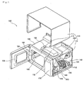
- FIG. 1 is an exploded perspective view of a microwave oven provided with a base cover structure according to the present invention.
- a microwave oven 100 provided with a base cover structure, includes an outer case 110 forming the exterior, an electrical component chamber 140 protected by the outer case 110 and mounted with a plurality of electrical components, a cavity 130 to which food is to be accommodated for cooking, an upper duct (not shown) installed above the cavity 130, and a door 120 installed at a front of the cavity 130.
- the outer case 110 forms the exterior of the microwave oven 100 and protects the cavity 130 located therein.
- the outer case 110 may be made of an iron plate that has a desired strength.
- the outer case 110 includes parts installed around the cavity 130: an upper cover 111 to cover the top and each side of the cavity 130; a base cover 200 to protect the bottom of the cavity 130; a front cover 112 to form the front of the cavity 130; and a back cover 113 to protect the rear of the cavity 130.
- a door 120 is installed at the front of the front cover 112, and a control panel 170 is provided beside the door 120, the control panel 170 being provided with a plurality of buttons for inputting operational conditions of the microwave oven 100.
- the base cover 200 protects the bottom of the cavity 130 and also supports the cavity 130 and various kinds of electrical components, the base cover 200 may be made of an iron plate having a desired strength.
- a bottom surface of the base cover 200 is spaced a predetermined distance apart from the bottom of the cavity 130. The base cover 200 will be described more fully with respect to the accompanying drawings.
- the cavity 130 is a place where food is cooked.
- the cavity 130 has a box-like shape with a front opening. Food is inserted and took out through the opening before and after cooking.
- the door 120 opens and closes the opening.
- the cavity 130 is formed by the combination of an upper plate 181, a side plate 183, a lower plate 182, and a rear plate (not shown).
- the upper plate 181 is provided at an upper outer side with a waveguide 150 for guiding a microwave produced by a magnetron to the cavity 130.
- a synchronous motor 160 is mounted on one side of the waveguide 150 for driving a stirrer fan.
- the stirrer fan (not shown) is mounted between the upper plate 181 and the upper duct, the upper duct being installed under the upper plate 181.
- the waveguide 150 is also installed at lower outer side of the cavity 130 besides the upper outer side of the upper plate 181, such that the microwave can be directed to the cavity 130 in downward and upward directions.
- the electric component chamber 140 is located at a right or left portion inside the outer case 110 to accommodate a plurality of electrical components.
- the plurality of electrical components includes a magnetron 146 generating a microwave, a transformer 142 converting low voltage to high voltage for applying high voltage to the magnetron 146, a blower fan 144 blowing away an warm air heated by the plurality of electrical components during the generation of the microwave, and a capacitor 141 storing an electric charge for the transformer 142.
- a vertical barrier 143 divides the electric component chamber 140 into two portions to separate the transformer 142 and the blower fan 144.
- the transformer 142, the blower fan 144, the capacitor 141, and the barrier 143 are fixed on a sub plate.
- the sub plate is spaced apart from the base cover 200 in an upward direction.
- the transformer 142 and the magnetron 146 are used to generate the microwave in the cavity 130. During the generation of the microwave for cooking, a heat is also generated from the electric components and thereby the temperature of the cavity 130 increases.
- the blower fan 144 For cooling the cavity 130, the blower fan 144 sucks outer air and blows the air to the hot electrical components.
- the door 120 is opened to place food into the cavity 130, the door 120 is closed and cooking conditions such as heating time are set using the buttons of the control panel 170. After that, by pressing a start button, the electrical components of the electric component chamber 140 are powered on, and the magnetron 146 generates a microwave. The generated microwave is directed into the cavity 130 through the waveguide 150. The microwave directed into the cavity 130 is reflected throughout the cavity 130 by the stirrer fan installed upper and lower side of the cavity 130, thereby evenly heating the food.
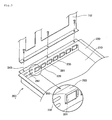
- FIG. 2 is a partial perspective view showing a front of a base cover according to the present invention
- FIG. 3 is a partial perspective view showing a rear of a front stepped portion of a base cover according to the present invention.
- the base cover 200 includes a cover body 210, a front stepped portion 220 bent upwardly at a front end of the cover body 210 with a predetermined height, side stepped portions 230, and a rear stepped portion (not shown).
- the cover body 210 forms a bottom of the base cover 200 to protect a lower side of the cavity 130 and to form a bottom of the electric component chamber 140.
- the front stepped portion 220 is secondly bent forwardly at its end to form an extended portion 240.
- the front cover 112 is fixed to the extended portion 240, and a front lower side of the cavity 130 is accommodated and supported by the extended portion 240.
- the front stepped portion 220 includes a plurality of air intake holes 260.
- the air intake hole 260 can also be formed in the side stepped portions 230 and/or the rear stepped portion.
- the air intake hole 260 includes cavity intake holes 261 defined under the cavity 130, and panel intake holes 262 defined under the control panel 170.
- the cavity intake holes 261 are defined through the front stepped portion 220, and the panel intake holes 262 are defined at a right side of the cavity intake holes 261 when viewed from the front (refer to FIG. 2 ).
- the sizes of the panel intake holes 262 are smaller than those of the cavity intake holes 261 to prevent users from inserting fingers, sticks or the like into the electric component chamber 140, thereby protecting the user from electricity during the operation of microwave oven 100.
- Reinforcement ribs 250 are provided at a rear surface of the front stepped portion 220 to enhance the strength of the front stepped portion 220 and to prevent deformation of the air intake holes 260.
- the reinforcement ribs 250 are protruded backwardly from peripheries of the cavity intake holes 261, and each of the reinforcement ribs 250 is formed into " ⁇ "-like shape surrounding a top and each side of the cavity intake hole 261. Also, the reinforcement ribs 250 can be protruded forwardly from the peripheries of the cavity intake holes 261. In addition, the reinforcement ribs 250 can be formed around the panel intake holes 262.
- the reinforcement ribs 250 bent from the front stepped portion 220, are integrally formed with the front stepped portion 220.
- the reinforcement ribs 250 are formed at the rear surface of the front stepped portion 220 to enhance the strength of the front stepped portion 220, thereby preventing the air intake holes 260 from deformation.
- the base cover 200 is made of an iron plate by using a blanking process. At the same blanking process is also formed the air intake holes 260. The front stepped portion 220 and the side stepped portions 230 are also bent during the blanking process. In this manner, the base cover 200 is provided with the front stepped portion 220 having the air intake holes 260 and the side stepped portions 230.
- the air intake holes 260 can be formed using a separate process after the front stepped portion 220 and the side stepped portions 230 are formed.
- the front stepped portion 220, the side stepped portions 230, and the air intake holes 260 of the base cover 200 may be formed using another process or different procedure according to choice of designer or manufacturer's convenience.
- the front stepped portion 220 and the cavity intake holes 261 are formed through bending and punching processes with selected sizes and directions by adjusting the bending/punching press and die.
- the die When using the die to process the iron plate, the die normally includes an upper die and a lower die, between which the iron plate is inserted for the bending and punching.
- the iron plate is placed on the lower die and the press makes the upper die strike the iron plate to make the base cover 200 to have the air intake holes 260.
- the lower die forms the air intake holes 260 and at the same time bends peripheries of the cavity intake holes 261 upwardly to form the protruded reinforcement ribs 250.
- a portion, in which the air intake holes 260 are formed is bent upwardly to form the front stepped portion 220, such that the base cover 200 can have the air intake holes 260 and the reinforcement ribs 250 at its front stepped portion 220.
- the reinforcement ribs 250 are directed to protrude in the rear direction of the front stepped portion 220.
- a base cover of microwave oven is provided with reinforcement ribs that are formed around air intake holes of a front stepped portion according to the present invention, such that the base cover can support the microwave oven more securely and the air intake holes can be reliably protected from deformation, thereby increasing industrial applicability.
Description
- The present invention is related to a microwave oven and base cover of the microwave oven, and more particularly, to a microwave oven and base cover of the microwave oven, in which structure of a base cover is improved to have an enhanced strength.
- Generally, a microwave oven is a device that is used to heat food by radiating microwave generated from a magnetron to the food when electric current is applied to electric components of the device.
- Such a microwave oven is classified into a household microwave oven having a small magnetron and a commercial microwave oven having a large (or a plurality of) magnetron.
- The microwave oven is further classified according to a heating method into a glass tray method rotating the food and a stirrer fan method scattering microwave radiated into the cavity. The former is generally applied to the household microwave oven while the latter is applied to the commercial microwave oven.
- Since the commercial microwave oven is generally used at convenience stores where the microwave oven is frequently used and restaurants where a large amount of the food should be quickly heated, the microwave oven needs relatively high power output compared with the household microwave oven.
- The structure of the related art microwave oven will now be described.
- A conventional microwave oven includes an outer case forming the exterior of the microwave oven, a cavity formed in the outer case to load food therein, a magnetron installed at one side of the cavity to generate a microwave, an electric component chamber accommodating various kinds of electric components such as a transformer, and a door for opening and closing an opening of the cavity.
- The outer case includes an upper cover, a side cover, and a base cover to cover the top, side, and bottom of the cavity, respectively. The upper cover is spaced a predetermined distance apart from the top of the cavity. The base cover is bent upward at its periphery to form a stepped portion having a predetermined height and thereby the base cover is also spaced apart from the bottom of the cavity. A plurality of air intake holes are defined at a front part of the stepped portion of the base cover to allow an air inflow. The air sucked through the air intake holes is directed to the space formed by the stepped portion between the base cover and the bottom of the cavity.
- Further, an air filter is installed on a front of the air intake holes to prevent foreign particles contained in the inflow air from entering the microwave oven.
- However, the base cover having the air intake holes according to the related art has the following problems.
- When a blower fan installed in the electric component chamber is driven, an outside air is directed into the microwave oven through air intake holes formed in the stepped portion of the base cover. Since the stepped portion supports the cavity and the electric component chamber that are located above the base cover, a lasting load deforms the air intake holes and as well the stepped portion. This deformation causes the microwave oven to incline to one side, and the inclination of the microwave oven causes improper cooking of the food loaded in the cavity.
- Further, the deformation of the stepped portion may decrease the sizes of the air intake holes to cause decrease of airflow rate. Therefore, the electric component chamber cannot be cooled sufficiently and thereby the microwave oven will operate abnormally.
-
US 4,332,992 A describes an air flow system for combination microwave and convection oven. Herein, a combination electric convection and microwave oven comprises an oven cavity, an electrical resistance heater, a magnetron, and a dual-end blower driven by a blower motor. The magnetron and the motor are cooled by the flow of air through a second blower wheel that is powered by the motor. The air is drawn into the oven through an opening in a base part of the oven, passes through the electrical component compartment including a transformer and enters the blower wheel. From there it is forced past cooling fins for the magnetron. If a diverter is open, the air is exhausted from the oven through a vent located in a base part of the oven. -
US 5,286,940 A describes a microwave oven break away element trim kit. Herein, a microwave oven is mounted in a rectangular opening in a wall by means of U-shaped support rails on a bottom of the opening with the door opening and control end of the oven extending outward relative to the face of the wall. A front facing trim kit for mounting the microwave oven includes upper and lower trim air vent elements, respectively, and opposite side upright trim elements, respectively, providing front trim facing above and below and to opposite sides surrounding the front face of the microwave oven. -
EP 0 870 991 A2 describes a heat cooker. Herein, a microwave oven comprises a base part having a back cover with a U-shaped cross section, which is a stick-like member extending in the direction from the right to the left of the microwave oven, partially having ventholes. When an oven heating is conducted, a natural convection generated in the apparatus body by heating of the heater generates, in this space, a cooling air flow that flows to the inside of the apparatus body from the outside. A fresh air flows in through ventilation slits and passes over a plate-like body, with a part of the air flowing into the apparatus body through ventholes of the bottom board and accessories by the vertical pressing pieces and flows into the apparatus body through ventholes. Moreover, a fresh air can also be taken in through ventholes formed on the bottom surface of a storage body section. -
US 4,666,113 A describes a device for mounting a cooking apparatus. Herein, a microwave oven body is provided with a microwave heating chamber, whose front opening is opened and closed by a door and an electric apparatus chamber positioned behind a control panel. Upon driving a cooling device, air is sucked as a cooling fluid into a rear portion of a vertical partition wall provided in an electric apparatus chamber through a large number of suction holes formed in the rear portion of an outer bottom wall on the electric apparatus chamber side. A part of the air is flown through the left side of the heating chamber downwardly and a large number of discharge holes formed on the left side of the outer bottom wall through which the air is discharged outside. The microwave oven body is provided with also a synthetic resin structure fixedly mounted on the lower portion thereof. The structure is provided with a right-hand projecting portion and a left-hand projecting portion, which project downward, on the right side and left side thereof respectively, the both projecting portions being provided with an air hole on the front portion and side portion thereof, respectively. Thus, air is sucked into air holes at a right-hand projecting portion into suction holes and then discharged through air holes in a left-hand projecting portion flowing from discharge holes. - It is an object of the present invention to provide a microwave oven protecting the user from electricity during the operation of the same while ensuring at the same time a reliable and sufficient air inflow capability.
- This object is solved by the microwave oven according to claim 1. Further advantages, refinements and embodiments of the invention are described in the respective sub-claims.
- Accordingly, the present invention is directed to a microwave oven and base cover thereof that substantially obviates one or more of the problems due to limitations and disadvantages of the related art.
- The present invention is further directed to a base cover structure, in which an air intake hole defined in a stepped portion of a base cover is designed to have improved structure and thereby the base cover supporting a cavity and various kinds of electric components can enhance its strength. The present invention is furthermore directed to a base cover structure that allows sufficient air inflow through an air intake hole toward the inside of a microwave oven.
- There is provided a microwave oven including: a cavity in which food is cooked; and a base cover having: a cover body installed under the cavity and contacting a mounting surface, a stepped portion bent upward from an end of the cover body for supporting the cavity, at least one air intake hole defined in the stepped portion for sucking an outside air, and a reinforcement rib protruded forwardly and/or backwardly from a periphery of the air intake hole.
- In another aspect , there is provided a microwave oven including: a cavity for accommodating food for cooking; a control panel for inputting a cooking condition; a cover body installed under the cavity; a front stepped portion bent upward from a font end of the cover body; an air intake hole having at least one cavity intake hole defined in the front stepped portion to allow an air inflow under the cavity and at least one panel intake hole to allow an air inflow under the control panel; and a reinforcement member formed at a periphery of the air intake hole.
- In a further another aspect, there is provided a base cover structure of a microwave oven, including: a cover body installed under a cavity, the cover body being spaced a predetermined distance apart from a bottom of the cavity; a stepped portion bent from an end of the base cover; at least one air intake hole defined in the stepped portion to allow an air inflow; a reinforcement rib formed by cutting and bending a part of the stepped portion to enhance the strength of the stepped portion and to prevent the air intake hole from deformation.
- In a still further another aspect, there is provided a microwave oven including: a cavity; and a base cover having: a stepped portion bent upwardly from a bottom of the cover body for supporting the cavity, a cavity intake hole defined in the stepped portion that is disposed under the cavity, a panel intake hole defined beside the cavity intake hole with a size smaller than the cavity intake hole, and a reinforcement member protruded from a periphery of the cavity intake hole and/or from a periphery of the panel intake hole.
- A base cover structure and microwave oven having the same, having the above-mentioned construction according to the present invention, provides more reliable supporting for a cavity and electric components by enhancing the strength of the base cover.
- Further, a reinforcement structure is applied around an air intake hole to prevent the air intake hole from deformation, and thereby a stepped portion where the air intake hole is defined can securely support a cavity of microwave oven without deformation.
- Furthermore, there is no deformation of an air intake hole defined at a front stepped portion of a base cover, such that an indoor air can be sucked at a constant rate through the air intake hole toward an inside of a microwave oven and thereby electric components in an electric component chamber can be cooled properly.
- The accompanying drawings, which are included to provide a further understanding of the invention and are incorporated in and constitute a part of this specification, illustrate embodiments of the invention and together with the description serve to explain the principles of the invention.
- In the drawings:
-
FIG. 1 is an exploded perspective view of a microwave oven provided with a base cover structure according to the present invention. -
FIG. 2 is a partial perspective view showing a front of a base cover according to the present invention. -
FIG. 3 is a partial perspective view showing a rear of a front stepped portion of a base cover according to the present invention. - Reference will now be made in detail to the preferred embodiments of the present invention, examples of which are illustrated in the accompanying drawings. It will be apparent to those skilled in the art that various modifications and variations can be made in the present invention. Thus, it is intended that the present invention covers the modifications and variations of this invention provided they come within the scope of the appended claims and their equivalents.
-
FIG. 1 is an exploded perspective view of a microwave oven provided with a base cover structure according to the present invention. - Referring to
FIG. 1 , amicrowave oven 100, provided with a base cover structure, includes anouter case 110 forming the exterior, anelectrical component chamber 140 protected by theouter case 110 and mounted with a plurality of electrical components, acavity 130 to which food is to be accommodated for cooking, an upper duct (not shown) installed above thecavity 130, and adoor 120 installed at a front of thecavity 130. - The
outer case 110 forms the exterior of themicrowave oven 100 and protects thecavity 130 located therein. Theouter case 110 may be made of an iron plate that has a desired strength. - In detail, the
outer case 110 includes parts installed around the cavity 130: anupper cover 111 to cover the top and each side of thecavity 130; abase cover 200 to protect the bottom of thecavity 130; afront cover 112 to form the front of thecavity 130; and aback cover 113 to protect the rear of thecavity 130. Adoor 120 is installed at the front of thefront cover 112, and acontrol panel 170 is provided beside thedoor 120, thecontrol panel 170 being provided with a plurality of buttons for inputting operational conditions of themicrowave oven 100. Since thebase cover 200 protects the bottom of thecavity 130 and also supports thecavity 130 and various kinds of electrical components, thebase cover 200 may be made of an iron plate having a desired strength. A bottom surface of thebase cover 200 is spaced a predetermined distance apart from the bottom of thecavity 130. Thebase cover 200 will be described more fully with respect to the accompanying drawings. - The
cavity 130 is a place where food is cooked. Thecavity 130 has a box-like shape with a front opening. Food is inserted and took out through the opening before and after cooking. Thedoor 120 opens and closes the opening. - The
cavity 130 is formed by the combination of anupper plate 181, aside plate 183, alower plate 182, and a rear plate (not shown). Theupper plate 181 is provided at an upper outer side with awaveguide 150 for guiding a microwave produced by a magnetron to thecavity 130. Asynchronous motor 160 is mounted on one side of thewaveguide 150 for driving a stirrer fan. The stirrer fan (not shown) is mounted between theupper plate 181 and the upper duct, the upper duct being installed under theupper plate 181. - The
waveguide 150 is also installed at lower outer side of thecavity 130 besides the upper outer side of theupper plate 181, such that the microwave can be directed to thecavity 130 in downward and upward directions. - The
electric component chamber 140 is located at a right or left portion inside theouter case 110 to accommodate a plurality of electrical components. - The plurality of electrical components includes a
magnetron 146 generating a microwave, atransformer 142 converting low voltage to high voltage for applying high voltage to themagnetron 146, ablower fan 144 blowing away an warm air heated by the plurality of electrical components during the generation of the microwave, and acapacitor 141 storing an electric charge for thetransformer 142. - A
vertical barrier 143 divides theelectric component chamber 140 into two portions to separate thetransformer 142 and theblower fan 144. Thetransformer 142, theblower fan 144, thecapacitor 141, and thebarrier 143 are fixed on a sub plate. The sub plate is spaced apart from thebase cover 200 in an upward direction. - In detail, the
transformer 142 and themagnetron 146 are used to generate the microwave in thecavity 130. During the generation of the microwave for cooking, a heat is also generated from the electric components and thereby the temperature of thecavity 130 increases. - For cooling the
cavity 130, theblower fan 144 sucks outer air and blows the air to the hot electrical components. - The operation of the
microwave oven 100, having above-mentioned elements, will now be described. - The
door 120 is opened to place food into thecavity 130, thedoor 120 is closed and cooking conditions such as heating time are set using the buttons of thecontrol panel 170. After that, by pressing a start button, the electrical components of theelectric component chamber 140 are powered on, and themagnetron 146 generates a microwave. The generated microwave is directed into thecavity 130 through thewaveguide 150. The microwave directed into thecavity 130 is reflected throughout thecavity 130 by the stirrer fan installed upper and lower side of thecavity 130, thereby evenly heating the food. -
FIG. 2 is a partial perspective view showing a front of a base cover according to the present invention, andFIG. 3 is a partial perspective view showing a rear of a front stepped portion of a base cover according to the present invention. - Referring to
FIGs 2 and3 , thebase cover 200 includes acover body 210, a front steppedportion 220 bent upwardly at a front end of thecover body 210 with a predetermined height, side steppedportions 230, and a rear stepped portion (not shown). - The
cover body 210 forms a bottom of thebase cover 200 to protect a lower side of thecavity 130 and to form a bottom of theelectric component chamber 140. - The front stepped
portion 220 is secondly bent forwardly at its end to form anextended portion 240. Thefront cover 112 is fixed to theextended portion 240, and a front lower side of thecavity 130 is accommodated and supported by theextended portion 240. - The front stepped
portion 220 includes a plurality of air intake holes 260. Theair intake hole 260 can also be formed in the side steppedportions 230 and/or the rear stepped portion. - The
air intake hole 260 includes cavity intake holes 261 defined under thecavity 130, and panel intake holes 262 defined under thecontrol panel 170. In other words, the cavity intake holes 261 are defined through the front steppedportion 220, and the panel intake holes 262 are defined at a right side of the cavity intake holes 261 when viewed from the front (refer toFIG. 2 ). - The sizes of the panel intake holes 262 are smaller than those of the cavity intake holes 261 to prevent users from inserting fingers, sticks or the like into the
electric component chamber 140, thereby protecting the user from electricity during the operation ofmicrowave oven 100. -
Reinforcement ribs 250 are provided at a rear surface of the front steppedportion 220 to enhance the strength of the front steppedportion 220 and to prevent deformation of the air intake holes 260. - In detail, the
reinforcement ribs 250 are protruded backwardly from peripheries of the cavity intake holes 261, and each of thereinforcement ribs 250 is formed into "⊏"-like shape surrounding a top and each side of thecavity intake hole 261. Also, thereinforcement ribs 250 can be protruded forwardly from the peripheries of the cavity intake holes 261. In addition, thereinforcement ribs 250 can be formed around the panel intake holes 262. - The
reinforcement ribs 250, bent from the front steppedportion 220, are integrally formed with the front steppedportion 220. - As described above, the
reinforcement ribs 250 are formed at the rear surface of the front steppedportion 220 to enhance the strength of the front steppedportion 220, thereby preventing the air intake holes 260 from deformation. - The process of forming the
reinforcement ribs 250 at the rear surface of the front steppedportion 220 will now be described. - The
base cover 200 is made of an iron plate by using a blanking process. At the same blanking process is also formed the air intake holes 260. The front steppedportion 220 and the side steppedportions 230 are also bent during the blanking process. In this manner, thebase cover 200 is provided with the front steppedportion 220 having the air intake holes 260 and the side steppedportions 230. Herein, the air intake holes 260 can be formed using a separate process after the front steppedportion 220 and the side steppedportions 230 are formed. - Though the process of forming the
base cover 200 is described above, the front steppedportion 220, the side steppedportions 230, and the air intake holes 260 of thebase cover 200 may be formed using another process or different procedure according to choice of designer or manufacturer's convenience. - The processes of forming the
reinforcement ribs 250, protruded backwardly from the peripheries of the cavity intake holes 261, will not be described. - The front stepped
portion 220 and the cavity intake holes 261 are formed through bending and punching processes with selected sizes and directions by adjusting the bending/punching press and die. - When using the die to process the iron plate, the die normally includes an upper die and a lower die, between which the iron plate is inserted for the bending and punching.
- In detail, the iron plate is placed on the lower die and the press makes the upper die strike the iron plate to make the
base cover 200 to have the air intake holes 260. Herein, the lower die forms the air intake holes 260 and at the same time bends peripheries of the cavity intake holes 261 upwardly to form the protrudedreinforcement ribs 250. After that, a portion, in which the air intake holes 260 are formed, is bent upwardly to form the front steppedportion 220, such that thebase cover 200 can have the air intake holes 260 and thereinforcement ribs 250 at its front steppedportion 220. According to the above processes, thereinforcement ribs 250 are directed to protrude in the rear direction of the front steppedportion 220. - The above-mentioned processes are exemplary illustrated. The processes can be changed according to manufacturing equipment and convenience in design.
- A base cover of microwave oven is provided with reinforcement ribs that are formed around air intake holes of a front stepped portion according to the present invention, such that the base cover can support the microwave oven more securely and the air intake holes can be reliably protected from deformation, thereby increasing industrial applicability.
Claims (7)
- A microwave oven (100) comprising:- a cavity (130) in which food is cooked; and- an electrical component chamber (140) for mounting with a plurality of electrical components and a control panel (170) both provided beside the cavity (130);- a base cover (200) having:- a cover body (210) installed under the cavity (130) and contacting a mounting surface,- a stepped portion (220, 230) bent upward from an end of the cover body (210) for supporting the cavity (130), and- at least one air intake hole (260) defined in the stepped portion (220, 230) for sucking an outside air,characterized by a reinforcement rib (250) protruded forwardly and/or backwardly from a periphery of the air intake hole (260) for reinforcing the air intake hole (260), and characterized in that the at least one air intake hole (260) includes a cavity intake hole (261) defined under the cavity (130), and a panel intake hole (262) defined under the control panel (170), and the size of the cavity intake hole (261) is larger than that of the panel intake hole (262) to prevent users from inserting foreign objects into the electric component chamber (140).
- The microwave oven (100) according to claim 1, wherein the stepped portion (220) is bent upwardly from a front end of the cover body (210) with a predetermined height.
- The microwave oven (100) according to claim 1, wherein the stepped portion (230) is bent upwardly from a side end of the cover body (210) with a predetermined height.
- The microwave oven (100) according to claim 1, wherein the reinforcement rib (250) is formed at an upper periphery and a side periphery of the cavity intake hole (261).
- The microwave oven (100) according to claim 1, wherein the reinforcement rib (250) has a "⊏"-shaped section.
- The microwave oven (100) according to claim 1, wherein the reinforcement rib (250) is formed by cutting and bending a part of the stepped portion (220, 230), such that the reinforcement rib (250) is protruded forwardly or backwardly from the periphery of the cavity intake hole (261).
- The microwave oven (100) according to claim 1, wherein the reinforcement rib (250) is integrally formed with the stepped portion (220, 230).
Applications Claiming Priority (2)
| Application Number | Priority Date | Filing Date | Title |
|---|---|---|---|
| KR1020030072130A KR100609174B1 (en) | 2003-10-16 | 2003-10-16 | Structure of Base plate for Microwave oven |
| PCT/KR2004/002622 WO2005038352A1 (en) | 2003-10-16 | 2004-10-14 | A microwave oven and a base cover thereof |
Publications (3)
| Publication Number | Publication Date |
|---|---|
| EP1680623A1 EP1680623A1 (en) | 2006-07-19 |
| EP1680623A4 EP1680623A4 (en) | 2011-01-12 |
| EP1680623B1 true EP1680623B1 (en) | 2014-07-02 |
Family
ID=36581297
Family Applications (1)
| Application Number | Title | Priority Date | Filing Date |
|---|---|---|---|
| EP04793484.9A Expired - Fee Related EP1680623B1 (en) | 2003-10-16 | 2004-10-14 | A microwave oven and a base cover thereof |
Country Status (5)
| Country | Link |
|---|---|
| US (1) | US20070194014A1 (en) |
| EP (1) | EP1680623B1 (en) |
| KR (1) | KR100609174B1 (en) |
| CN (1) | CN100529550C (en) |
| WO (1) | WO2005038352A1 (en) |
Families Citing this family (3)
| Publication number | Priority date | Publication date | Assignee | Title |
|---|---|---|---|---|
| WO2009049081A1 (en) * | 2007-10-09 | 2009-04-16 | Acp, Inc. | Air circuit for cooking appliance including combination heating system |
| EP2527746B1 (en) * | 2010-01-21 | 2020-06-24 | LG Electronics Inc. | Control panel for a microwave oven |
| WO2023140798A1 (en) * | 2021-09-08 | 2023-07-27 | Mamur Teknoloji Sistemleri San. A.S. | A hob with reinforcement element of a base plate |
Family Cites Families (13)
| Publication number | Priority date | Publication date | Assignee | Title |
|---|---|---|---|---|
| US4108139A (en) * | 1976-04-12 | 1978-08-22 | The Tappan Company | Convection oven |
| US4327274A (en) * | 1978-08-21 | 1982-04-27 | General Electric Company | Ventilation system for combination microwave oven and exhaust vent |
| US4332992A (en) * | 1979-12-19 | 1982-06-01 | Amana Refrigeration, Inc. | Air flow system for combination microwave and convection oven |
| JPS61228228A (en) * | 1985-04-03 | 1986-10-11 | Sanyo Electric Co Ltd | Installment for cooking utentil |
| KR910003902Y1 (en) * | 1986-09-24 | 1991-06-07 | 삼성전자 주식회사 | Cooling equipment of electronic range |
| JPS63201427A (en) * | 1987-02-16 | 1988-08-19 | Matsushita Electric Ind Co Ltd | Heating apparatus |
| US5286940A (en) * | 1992-08-28 | 1994-02-15 | Leeds Harlan S | Microwave oven break away element trim kit |
| KR100229138B1 (en) * | 1997-03-22 | 1999-11-01 | 윤종용 | A filter in microwave oven |
| JP3113621B2 (en) * | 1997-04-07 | 2000-12-04 | 三洋電機株式会社 | Cooking device |
| KR100286026B1 (en) * | 1998-07-29 | 2001-06-01 | 윤종용 | microwave |
| KR20000014344A (en) * | 1998-08-20 | 2000-03-06 | 윤종용 | Microwave oven |
| KR20030074008A (en) * | 2002-03-15 | 2003-09-19 | 주식회사 엘지이아이 | Outer casing for microwave oven |
| KR100512676B1 (en) * | 2002-06-18 | 2005-09-07 | 삼성전자주식회사 | Wall mounting type microwave oven |
-
2003
- 2003-10-16 KR KR1020030072130A patent/KR100609174B1/en not_active IP Right Cessation
-
2004
- 2004-10-14 EP EP04793484.9A patent/EP1680623B1/en not_active Expired - Fee Related
- 2004-10-14 CN CNB2004800337984A patent/CN100529550C/en not_active Expired - Fee Related
- 2004-10-14 US US10/575,859 patent/US20070194014A1/en not_active Abandoned
- 2004-10-14 WO PCT/KR2004/002622 patent/WO2005038352A1/en active Application Filing
Also Published As
| Publication number | Publication date |
|---|---|
| KR100609174B1 (en) | 2006-08-02 |
| WO2005038352A1 (en) | 2005-04-28 |
| EP1680623A4 (en) | 2011-01-12 |
| US20070194014A1 (en) | 2007-08-23 |
| KR20050036442A (en) | 2005-04-20 |
| CN1882810A (en) | 2006-12-20 |
| EP1680623A1 (en) | 2006-07-19 |
| CN100529550C (en) | 2009-08-19 |
Similar Documents
| Publication | Publication Date | Title |
|---|---|---|
| US5798505A (en) | Microwave oven with upwardly directed air discharge duct | |
| EP0875723A1 (en) | Microwave oven | |
| EP1615471A2 (en) | Microwave oven | |
| GB2357413A (en) | Fan-assisted oven with heating element in cooking chamber | |
| EP1220576A2 (en) | Device for cooling electric equipment of hooded microwave oven | |
| EP1221827B1 (en) | Hood apparatus of ventilation hooded microwave oven | |
| US7820953B2 (en) | Microwave oven and radiating structure of microwave in microwave oven | |
| EP1680623B1 (en) | A microwave oven and a base cover thereof | |
| US6956191B2 (en) | Microwave oven having a projection door which extends a cooking chamber of the microwave oven | |
| EP1649220B1 (en) | Air flow system in an oven | |
| EP0825802A2 (en) | Microwave oven | |
| US20070138171A1 (en) | Microwave oven and an upper duct structure thereof | |
| CN110213851B (en) | Heating cooker | |
| EP4350220A1 (en) | Electric range | |
| KR100621253B1 (en) | A fixing structure of ventilation of Cabity for Microwave oven | |
| KR101207306B1 (en) | convection heating unit and heating cooker having the same | |
| KR200207704Y1 (en) | microwave | |
| KR100635661B1 (en) | A Lower passage of Cavity for Mocrowave oven | |
| EP0584934A1 (en) | Heating apparatus | |
| KR100582295B1 (en) | A structure of Back-plate for Microwave oven | |
| KR100582293B1 (en) | A structure of ventilation duct in electric room for Microwave oven | |
| KR100582305B1 (en) | A structure of back-plate for Microwave oven | |
| EP0868113A2 (en) | Electrical appliance | |
| KR20050086116A (en) | Mounting structure of deodorizing filter for electric oven | |
| KR20060032682A (en) | A combination structure of base department for electric oven |
Legal Events
| Date | Code | Title | Description |
|---|---|---|---|
| PUAI | Public reference made under article 153(3) epc to a published international application that has entered the european phase |
Free format text: ORIGINAL CODE: 0009012 |
|
| 17P | Request for examination filed |
Effective date: 20060426 |
|
| AK | Designated contracting states |
Kind code of ref document: A1 Designated state(s): DE |
|
| DAX | Request for extension of the european patent (deleted) | ||
| RBV | Designated contracting states (corrected) |
Designated state(s): DE |
|
| A4 | Supplementary search report drawn up and despatched |
Effective date: 20101209 |
|
| 17Q | First examination report despatched |
Effective date: 20110531 |
|
| GRAP | Despatch of communication of intention to grant a patent |
Free format text: ORIGINAL CODE: EPIDOSNIGR1 |
|
| INTG | Intention to grant announced |
Effective date: 20140207 |
|
| RIN1 | Information on inventor provided before grant (corrected) |
Inventor name: JEONG, EUI-SEOG |
|
| RAP1 | Party data changed (applicant data changed or rights of an application transferred) |
Owner name: LG ELECTRONICS INC. |
|
| GRAS | Grant fee paid |
Free format text: ORIGINAL CODE: EPIDOSNIGR3 |
|
| GRAA | (expected) grant |
Free format text: ORIGINAL CODE: 0009210 |
|
| AK | Designated contracting states |
Kind code of ref document: B1 Designated state(s): DE |
|
| REG | Reference to a national code |
Ref country code: DE Ref legal event code: R096 Ref document number: 602004045413 Country of ref document: DE Effective date: 20140814 |
|
| REG | Reference to a national code |
Ref country code: DE Ref legal event code: R097 Ref document number: 602004045413 Country of ref document: DE |
|
| PLBE | No opposition filed within time limit |
Free format text: ORIGINAL CODE: 0009261 |
|
| STAA | Information on the status of an ep patent application or granted ep patent |
Free format text: STATUS: NO OPPOSITION FILED WITHIN TIME LIMIT |
|
| 26N | No opposition filed |
Effective date: 20150407 |
|
| PGFP | Annual fee paid to national office [announced via postgrant information from national office to epo] |
Ref country code: DE Payment date: 20170905 Year of fee payment: 14 |
|
| REG | Reference to a national code |
Ref country code: DE Ref legal event code: R119 Ref document number: 602004045413 Country of ref document: DE |
|
| PG25 | Lapsed in a contracting state [announced via postgrant information from national office to epo] |
Ref country code: DE Free format text: LAPSE BECAUSE OF NON-PAYMENT OF DUE FEES Effective date: 20190501 |