EP4435328A1 - Haushaltsgerät mit einem racksystem - Google Patents
Haushaltsgerät mit einem racksystem Download PDFInfo
- Publication number
- EP4435328A1 EP4435328A1 EP24163423.7A EP24163423A EP4435328A1 EP 4435328 A1 EP4435328 A1 EP 4435328A1 EP 24163423 A EP24163423 A EP 24163423A EP 4435328 A1 EP4435328 A1 EP 4435328A1
- Authority
- EP
- European Patent Office
- Prior art keywords
- locking
- household appliance
- locking element
- appliance according
- section
- Prior art date
- Legal status (The legal status is an assumption and is not a legal conclusion. Google has not performed a legal analysis and makes no representation as to the accuracy of the status listed.)
- Granted
Links
Images












Classifications
-
- A—HUMAN NECESSITIES
- A47—FURNITURE; DOMESTIC ARTICLES OR APPLIANCES; COFFEE MILLS; SPICE MILLS; SUCTION CLEANERS IN GENERAL
- A47J—KITCHEN EQUIPMENT; COFFEE MILLS; SPICE MILLS; APPARATUS FOR MAKING BEVERAGES
- A47J37/00—Baking; Roasting; Grilling; Frying
- A47J37/06—Roasters; Grills; Sandwich grills
- A47J37/067—Horizontally disposed broiling griddles
-
- F—MECHANICAL ENGINEERING; LIGHTING; HEATING; WEAPONS; BLASTING
- F24—HEATING; RANGES; VENTILATING
- F24C—DOMESTIC STOVES OR RANGES ; DETAILS OF DOMESTIC STOVES OR RANGES, OF GENERAL APPLICATION
- F24C15/00—Details
- F24C15/16—Shelves, racks or trays inside ovens; Supports therefor
-
- A—HUMAN NECESSITIES
- A47—FURNITURE; DOMESTIC ARTICLES OR APPLIANCES; COFFEE MILLS; SPICE MILLS; SUCTION CLEANERS IN GENERAL
- A47B—TABLES; DESKS; OFFICE FURNITURE; CABINETS; DRAWERS; GENERAL DETAILS OF FURNITURE
- A47B57/00—Cabinets, racks or shelf units, characterised by features for adjusting shelves or partitions
- A47B57/58—Cabinets, racks or shelf units, characterised by features for adjusting shelves or partitions with means for adjusting partitions horizontally
- A47B57/583—Cabinets, racks or shelf units, characterised by features for adjusting shelves or partitions with means for adjusting partitions horizontally by sliding
- A47B57/585—Cabinets, racks or shelf units, characterised by features for adjusting shelves or partitions with means for adjusting partitions horizontally by sliding with connection means slidable in a rail
-
- A—HUMAN NECESSITIES
- A47—FURNITURE; DOMESTIC ARTICLES OR APPLIANCES; COFFEE MILLS; SPICE MILLS; SUCTION CLEANERS IN GENERAL
- A47B—TABLES; DESKS; OFFICE FURNITURE; CABINETS; DRAWERS; GENERAL DETAILS OF FURNITURE
- A47B88/00—Drawers for tables, cabinets or like furniture; Guides for drawers
- A47B88/40—Sliding drawers; Slides or guides therefor
- A47B88/423—Fastening devices for slides or guides
- A47B88/43—Fastening devices for slides or guides at cabinet side
-
- A—HUMAN NECESSITIES
- A47—FURNITURE; DOMESTIC ARTICLES OR APPLIANCES; COFFEE MILLS; SPICE MILLS; SUCTION CLEANERS IN GENERAL
- A47B—TABLES; DESKS; OFFICE FURNITURE; CABINETS; DRAWERS; GENERAL DETAILS OF FURNITURE
- A47B88/00—Drawers for tables, cabinets or like furniture; Guides for drawers
- A47B88/50—Safety devices or the like for drawers
- A47B88/57—Safety devices or the like for drawers preventing complete withdrawal of the drawer
-
- A—HUMAN NECESSITIES
- A47—FURNITURE; DOMESTIC ARTICLES OR APPLIANCES; COFFEE MILLS; SPICE MILLS; SUCTION CLEANERS IN GENERAL
- A47J—KITCHEN EQUIPMENT; COFFEE MILLS; SPICE MILLS; APPARATUS FOR MAKING BEVERAGES
- A47J36/00—Parts, details or accessories of cooking-vessels
- A47J36/16—Inserts
- A47J36/20—Perforated bases or perforated containers to be placed inside a cooking utensil ; Draining baskets, inserts with separation wall
-
- A—HUMAN NECESSITIES
- A47—FURNITURE; DOMESTIC ARTICLES OR APPLIANCES; COFFEE MILLS; SPICE MILLS; SUCTION CLEANERS IN GENERAL
- A47L—DOMESTIC WASHING OR CLEANING; SUCTION CLEANERS IN GENERAL
- A47L15/00—Washing or rinsing machines for crockery or tableware
- A47L15/42—Details
- A47L15/50—Racks ; Baskets
- A47L15/507—Arrangements for extracting racks, e.g. roller supports
-
- H—ELECTRICITY
- H05—ELECTRIC TECHNIQUES NOT OTHERWISE PROVIDED FOR
- H05B—ELECTRIC HEATING; ELECTRIC LIGHT SOURCES NOT OTHERWISE PROVIDED FOR; CIRCUIT ARRANGEMENTS FOR ELECTRIC LIGHT SOURCES, IN GENERAL
- H05B6/00—Heating by electric, magnetic or electromagnetic fields
- H05B6/64—Heating using microwaves
- H05B6/6408—Supports or covers specially adapted for use in microwave heating apparatus
-
- A—HUMAN NECESSITIES
- A47—FURNITURE; DOMESTIC ARTICLES OR APPLIANCES; COFFEE MILLS; SPICE MILLS; SUCTION CLEANERS IN GENERAL
- A47L—DOMESTIC WASHING OR CLEANING; SUCTION CLEANERS IN GENERAL
- A47L15/00—Washing or rinsing machines for crockery or tableware
- A47L15/42—Details
- A47L15/4251—Details of the casing
- A47L15/4257—Details of the loading door
- A47L15/4259—Arrangements of locking or security/safety devices for doors, e.g. door latches, switch to stop operation when door is open
-
- F—MECHANICAL ENGINEERING; LIGHTING; HEATING; WEAPONS; BLASTING
- F24—HEATING; RANGES; VENTILATING
- F24C—DOMESTIC STOVES OR RANGES ; DETAILS OF DOMESTIC STOVES OR RANGES, OF GENERAL APPLICATION
- F24C15/00—Details
- F24C15/16—Shelves, racks or trays inside ovens; Supports therefor
- F24C15/168—Shelves, racks or trays inside ovens; Supports therefor with telescopic rail systems
Definitions
- the present invention relates to a household appliance with an interior for accommodating a rack system, wherein a wall element is provided on opposite sides of the interior and a locking projection is arranged on at least one of the wall elements, wherein the rack system has a stationary part arranged in the interior and a part that can be moved at least partially in front of the interior via guides, and a locking element for releasable engagement with the locking projection is provided on the stationary part, which can be moved into an unlocked position via a driver on the movable part.
- an oven in which a rack system is arranged in an interior.
- the rack system comprises a stationary part that remains in the oven and a part that can be pulled out on the interior.
- a rotating latch locks the stationary part in the oven.
- the latch is pre-tensioned into the locked position by a spring and can be brought into engagement with a projection for locking.
- a driver ensures that the latch pivots against the spring force for unlocking.
- the use of a spring in the oven is disadvantageous because, especially at high temperatures, for example during pyrolysis cleaning, damage can be associated with an impairment of the pre-tensioning force.
- the locking mechanism requires numerous components, which makes assembly and production complex.
- a sliding device for a movable grid is shown, which can be moved on opposite sides via a guide in the extension direction.
- a hook is provided on the rear end of a stationary part, which can be moved against the force of a spring when the rack is pushed into a raised position. When the rack is pulled out, the hook engages behind a lock on the rear wall and is pre-tensioned into the locked position by the spring. The lock therefore requires additional installation space.
- a similar rack device is also shown in the US 2021/0071876 A1 .
- the rack system can be releasably engaged with a locking projection on a wall element via at least one locking element, wherein the locking element can be moved via a driver on the movable part of the rack system, and the locking element can be moved from a locking position via the driver into an unlocked position.
- the locking element is moved via the driver from a lowered locking position to a raised unlocked position or from a raised locking position to a lowered unlocked position.
- the driver can, for example, slide or pivot the locking element via a run-on slope and move it into the raised position, so that when the driver moves in the pull-out direction, the locking element can automatically be moved back into the lowered position. This enables a simple construction of the locking mechanism and reliable locking.
- the locking element can be moved from the unlocked position to the locked position solely by gravity.
- the locking element therefore does not have to be pre-tensioned into the locking position by a mechanical spring, thus avoiding the problem of susceptibility to errors caused by a spring.
- the lifting of the locking element from the lowered locking position to the raised unlocked position refers to the centre of gravity of the locking element, which is lower in the lowered locking position than in the raised, unlocked position.
- the movement of the locking element between these positions is preferably a sliding movement, a rotary movement or a combined sliding and rotary movement.
- the locking element can be mounted with a bearing section so that it can rotate about an axis, preferably about a horizontal axis or about an axis inclined to the horizontal.
- the locking element is preferably pivotably mounted on the stationary part.
- the locking element can be pivotably mounted about an axis that extends essentially parallel to the extension direction of the movable part.
- the locking element can be pivoted into a raised position by the driver, which is formed, for example, by an integral section of the stationary part, in order to unlock it.
- the locking element can be easily mounted on the stationary part if a clamp is fixed to it, which forms a bearing receptacle for the pivotable locking element.
- the clamp can, for example, be welded to the grid-shaped stationary part.
- the locking projection is arranged in the area of a front half of the wall element in relation to a pull-out direction of the movable part. This results in a compact structure and the rack system can be manufactured with the identical locking mechanism in different lengths.
- a locking section provided on the locking element can be subjected to pressure when a tensile force is applied to the stationary part in the extension direction.
- the locking section rests on the locking projection with a contact surface on the one hand and extends to a bearing or holding section on the stationary part.
- the locking section can therefore reliably absorb high forces.
- the locking element comprises an actuating section that can be brought into engagement with the driver, a locking section that can be placed on the locking projection and a bearing section for rotatably supporting the locking element, wherein the bearing section is arranged between the actuating section and the locking section.
- the locking element thus forms a double lever, in which the bearing section is provided in a central region and on opposite The actuating section and the locking section are provided on the sides of the bearing section, whereby "opposite” does not spatially refer to an opposite arrangement, but only to the design as a double lever, in which the bearing section is arranged between different levers, which can be rotated together.
- the double lever can be designed in one part or in multiple parts.
- the locking element preferably has a boom, by means of which the locking section of the locking element is prestressed into a raised locked position by gravity.
- the boom can be designed, for example, as a lever, which prestresses the locking element in a predetermined direction of rotation by gravity.
- the driver is preferably arranged in the vertical direction above an actuating section of the locking element and presses the actuating section downwards in the retracted position of the movable part.
- the actuating section can then be moved upwards, in particular pivoted, when the movable part is extended.
- the locking element is preferably made of a bent wire so that functionality is guaranteed even at high temperatures.
- the locking element can have an actuating section that interacts with the driver on the movable part and ensures a pivoting movement of the locking element.
- the locking element can have an integrally formed locking section that can be moved towards the wall element and can be moved into engagement with the locking projection.
- the stationary part can comprise a first rail and the movable part a second rail, which are held together by rolling elements.
- a pull-out extension middle rail can be provided between the first rail and the second rail, depending on how far the movable part of the rack system is to be moved in front of the interior.
- the rails are preferably part of a pull-out guide, which is arranged between the stationary part and the movable part of the rack system.
- a locking element can be provided on the stationary part adjacent to each wall element, which can be brought into engagement with a locking projection. This means that the stationary part is locked on opposite sides when the movable part of the rack system is pulled out of the interior.
- the locking element can be formed by a bent wire, a metal sheet or hook-shaped elements. The locking element preferably engages centrally on a locking projection near the rear wall or a side grille.
- the locking projection is made on a wall element from an embossed metal sheet.
- the locking projection can be formed integrally with a support strip that serves to accommodate the stationary part of the rack system, the locking projection being made, for example, by a V-shaped embossing.
- the locking projection is formed on a side grille that is fixed to a wall in the interior.
- the household appliance is designed as an oven.
- the household appliance can also be designed as a microwave, steamer or other device for preparing food.
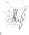
- a household appliance 1 is designed as an oven and comprises a housing 2, in particular made of a metal sheet, in which an interior 3 is provided.
- the interior 3 is open at a front and can be closed by a pivoting door 4.
- a wall element 5 is provided, which is made of a profiled metal sheet and has several support strips 6 for supporting food carriers or one or more rack systems 10.
- a locking projection 7 is formed on each support strip 6, which is made as an inwardly projecting V-shaped embossing, but can also be provided with other geometries on the wall element 5.
- the rack system 10 comprises a stationary part 11, which rests on support strips 6 on opposite sides and remains in the interior 3.
- the rack system 10 also comprises a movable part 12, which is held on opposite sides by guides on the stationary part 11 and can be moved into a position in front of the interior 3. If the movable part 12 is moved from the stationary part 11 into a pull-out position, the stationary part 11 is fixed to a wall element 5 via at least one locking mechanism.
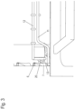
- a locking element 20 of the locking mechanism is shown, which is pivotably held on the stationary part 11.
- the locking element 20 is shown in an unlocked raised position and can pivot anti-clockwise when the movable part 12 is pulled out, so that a part of the locking element 20 gets behind the locking projection 7 and locks the stationary part 11 against being pulled out.
- the locking element 20 can be moved by a driver 13 which is formed on the movable part 12 of the rack system 10.
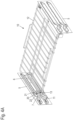
- a rack system 10 is shown with a section of the wall elements 5 in a retracted and unlocked position.
- the movable part 12 of the rack system 10 is held on the stationary part 11 via guides, in particular pull-out guides, and is formed by a grid.
- the movable part 12 can also be designed as a baking tray or other support.
- the stationary part 11 is also designed as a grid or frame and is supported on opposite sides on support strips 6.
- the rack system is arranged in the retracted position so that the driver 13 on the movable part 12 holds the locking element 20 in an unlocked position via an actuating section 21 and the rack system 10 can be pulled out of the interior 3 as a unit.
- the rack system 10 is in Figure 4B shown in an extension position, since the movable part 12 has been moved in the extension direction relative to the stationary part 11. As a result, the driver 13 has moved away from the actuating section 21 of the locking element 20, and this engages with a locking section 22 behind the locking projection 7, so that the stationary part 11 is locked to the wall 5.
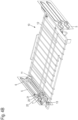
- FIG 5A only the stationary part 11 of the rack system 10 is shown in an unlocked position, resting on the support strips 6 of the walls 5.
- the locking element 20 is rotatably mounted on the stationary part 11, with the axis of rotation extending parallel to the pull-out direction.
- the movable part 12 is held on the stationary part 11 so that it can move via a pull-out guide and that the pull-out guide comprises a stationary rail 14 and a movable rail 15, which are held together by rolling elements.
- a pull-out-extending center rail can be arranged between the stationary rail 14 and the movable rail 15.
- a sliding guide can also be provided between the stationary part 11 and the movable part 12.
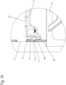
- the locking mechanism is shown in different positions.
- the locking element 20 is in a locked position and a locking portion 22 of the locking element 20 is arranged behind the locking projection 7 in the extension direction so that the stationary part 11 is blocked in the extension direction.
- the locking element 20 is rotatably held on a bracket 16 which forms a bearing receptacle.
- the bracket 16 can be welded to a rod of the stationary part 11.
- the locking element 20 also has an actuating portion 21 which projects obliquely upwards.
- driver 13 on the movable part 12 can contact the actuating section 21 so that the actuating section 21 is pivoted away from the wall element 5.
- the driver 13 is designed as a V-shaped section of a bent wire, but can also have a different shape.
- the locking element 20 is shown in the locked position.
- the bracket 16 forms a bearing receptacle for a part of the locking element 20, and the locking portion 22 can be Figure 7B for unlocking, it can be pivoted upwards in a clockwise direction.
- the locking element 20 In the unlocked position, the locking element 20 is thus in a higher position relative to the center of gravity than in a locked position.
- the locking section 22 and thus the locking element 20 can thus pivot automatically into the locking position by gravity when the movable part 11 is pulled out.
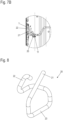
- the locking element 20 is shown, which is made of a bent metallic wire.
- the locking element 20 comprises the rod-shaped actuating section 21, which is formed integrally with a bearing section 23, which is arranged in the bearing receptacle of the clamp 16.
- the locking section 22, which can come to rest against the locking projection 7, is also formed integrally with the bearing section 23.
- a modified household appliance 1 which, as in the previous embodiment, has an interior 3 with a rack system 10, but a wall element 5' is provided which is not made of a stamped metal sheet, but comprises a side grille with horizontal bars 6' for supporting the rack system 10.
- the side grille also comprises bars with an integrally formed locking projection 7', which are formed by profiling the wire.
- the wall element 5' can be designed entirely as a side grille and can be fixed to a wall on the interior 3.
- the household appliance 1 is shown without the wall element 5', and it can be seen that the driver 13 of the movable part 12 of the rack system 10 contacts an actuating section 21 of a locking element 20 so that the locking element is moved into the unlocked position.
- the rack system 10 as in the previous embodiment, comprises pull-out guides on opposite sides between the movable part 12 and the stationary part 11.
- FIG 11 is the locking mechanism of the household appliance 1 of the Figure 9 shown.
- the locking element 20 comprises an actuating section 21 that projects obliquely upwards and can be contacted by the driver 13 in order to pivot the locking element 20 when retracting.
- the locking element 20 is in the lowered position and a locking section 22 engages behind a locking projection 7' so that the rack system 10 cannot be pulled out of the interior 3.
- the rack system 10 rests with the stationary part 11 on a support strip 6'.
- the modified locking element 20 is shown, which is again made of a metallic wire and has a rod-shaped actuating section 21 which is formed integrally with a bearing section 23.
- the bearing section 23 is followed by a locking section 22' which is shorter than the locking section 22 in Figure 8 and serves only as a stop that can be brought into engagement with the locking projection 7, 7'.
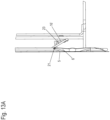
- FIG. 13A and 13B a modified locking mechanism for a rack system 10 is shown.
- the driver 13 can move the actuating portion 21 so that the locking portion 22 moves away from the wall element 5 was pivoted.
- the locking element 20 rotates in a modified clamp 16', which holds the bearing section 23 not parallel to the extension direction of the movable part 12 but at an angle to it, for example at an angle of less than 30° parallel to the extension direction of the movable part 12.
- the bearing section 23 is aligned horizontally here.
- FIG 14 a modified locking mechanism for a rack system 10 is shown, in which the locking element 20 is held in a modified bracket 16".
- the bearing section 23 is not aligned horizontally, but is held inclined to the horizontal.
- the bearing section 23 can be aligned at an angle of less than 30° parallel to the extension direction of the movable part 12.
- FIG 15 a modified household appliance 1 in the form of an oven is shown with a housing 2, in which a rack system 10 is arranged in an interior space 3.
- the housing 2 comprises a wall element 5 with several support strips 6 on opposite sides, and a stationary part 11 of the rack system 10 is placed on one of the support strips 6.
- a movable part 12 with a grid is held movable on the stationary part 11, with a pull-out guide 17 with rails that can be moved relative to one another being provided between the stationary part 11 and the movable part 12.
- FIG. 16 is removable, there is a locking element 30 below a driver 13, by means of which the stationary part 11 can be locked to a locking projection 7 on the wall element 5.
- the driver 13 is located above the locking element 30 and can pivot the locking element 30 when moving in or against the pull-out direction.
- FIG 17 the rack system 10 is shown between the two wall elements 5 in a retracted position.
- the movable part 12 is arranged above the stationary part 11 and between the two wall elements 5.
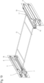
- FIG 19 the stationary part 11 of the rack system 10 is shown without the movable part 12.
- the stationary part 11 rests on a support bar 6 with a strut on opposite sides and has an upwardly projecting projection 19 in the rear area, which can be placed on the underside of a support bar 6 in order to prevent a tipping movement of the stationary part 11.
- a pull-out guide 17 with a stationary rail 14 and at least one movable rail 15 is provided on the stationary part 11 on opposite sides.
- the locking element 30 comprises an actuating section 31 which projects upwards and has a run-on slope against which the driver 13 comes when the movable part 12 is retracted in order to pivot the locking element 30.
- the locking element 30 further comprises a locking section 32 which is arranged adjacent to the locking projection 7 on the wall element 5 and ensures that the locking element 30 is locked in a raised position.
- a bearing section 33 is formed between the locking section 32 and the actuating section 31 and is mounted so as to be rotatable about an axis 18 of the stationary part 11.
- the bearing section 33 is arranged between the locking section 32 and the actuating section 31, and the locking element 30 is designed as a double lever with at least two lever arms.
- the locking element 30 is connected to a third lever in the form of a boom 34 which extends from the bearing section 33.
- the boom 34 forms a weight element in order to preload the locking element 30 about the axis 18 into a locked position.
- the locking element 30 is pivoted counterclockwise about the axis 18, as shown in Figure 21
- the locking element 30 is then oriented substantially horizontally and the locking portion 32 disengages from the locking portion 7 and the arm 34 projects substantially horizontally from the bearing portion 33.
- the locking element 30 is made of a bent and punched metal sheet, but it can also be made of a different material and be manufactured using a different process.
- the driver 13 is formed integrally with the movable part 12, but can also be attached to it as an additional part. It is also possible to fix or form the driver 13 on the movable rail 15 of the pull-out guide.
- At least one locking element 20 is provided on opposite sides of the rack system 10 in order to be able to securely fix the stationary part 11 in the household appliance 1.
Landscapes
- Engineering & Computer Science (AREA)
- Chemical & Material Sciences (AREA)
- Combustion & Propulsion (AREA)
- Mechanical Engineering (AREA)
- General Engineering & Computer Science (AREA)
- Food Science & Technology (AREA)
- Physics & Mathematics (AREA)
- Electromagnetism (AREA)
- Baking, Grill, Roasting (AREA)
- Electric Ovens (AREA)
- Transmission Devices (AREA)
Abstract
Description
- Die vorliegende Erfindung betrifft ein Haushaltsgerät mit einem Innenraum zur Aufnahme eines Racksystems, wobei an gegenüberliegenden Seiten des Innenraumes jeweils ein Wandelement vorgesehen ist und an mindestens einem der Wandelemente ein Verriegelungsvorsprung angeordnet ist, wobei das Racksystem ein im Innenraum angeordnetes stationäres Teil und ein über Führungen zumindest teilweise vor den Innenraum bewegbares Teil aufweist, und an dem stationären Teil ein Riegelelement zum lösbaren Eingriff mit dem Verriegelungsvorsprung vorgesehen ist, das über einen Mitnehmer an dem bewegbaren Teil in eine entriegelte Position bewegbar ist.
- In der
US 2012/0097147 A1 ist ein Backofen offenbart, bei dem ein Racksystem in einem Innenraum angeordnet ist. Das Racksystem umfasst einen stationären Teil, der im Backofen verbleibt, und einen auf dem Innenraum herausziehbaren Teil. Wenn der bewegbare Teil des Racksystems herausgezogen wird, sorgt ein drehbarer Riegel für eine Verriegelung des stationären Teils im Backofen. Dadurch wird die Sicherheit bei der Handhabung und Zubereitung von Speisen erhöht. Der Riegel ist dabei über eine Feder in die verriegelte Position vorgespannt und kann für eine Verriegelung mit einem Vorsprung in Eingriff gebracht werden. Bei einem Einfahren des bewegbaren Teils sorgt ein Mitnehmer für ein Verschwenken des Riegels gegen die Federkraft für eine Entriegelung. Der Einsatz einer Feder im Backofen ist nachteilig, weil gerade bei hohen Temperaturen, beispielsweise bei der Pyrolysereinigung, eine Beschädigung mit einer Beeinträchtigung der Vorspannkraft verbunden sein kann. Zudem erfordert der Verriegelungsmechanismus zahlreiche Bauteile, was die Montage und Herstellung aufwändig macht. - In der
US 10,548,396 B1 US 2021/0071876 A1 . - In der
US 10,876,737 B2 - Es ist daher Aufgabe der vorliegenden Erfindung, ein Haushaltsgerät zu schaffen, bei dem ein Racksystem mit einfachen Mitteln zuverlässig in einem Innenraum verriegelt werden kann.
- Diese Aufgabe wird mit einem Haushaltsgerät mit den Merkmalen des Anspruches 1 gelöst.
- Bei dem erfindungsgemäßen Haushaltsgerät kann das Racksystem über mindestens ein Riegelelement lösbar in Eingriff mit einem Verriegelungsvorsprung an einem Wandelement gebracht werden, wobei das Riegelelement über einen Mitnehmer an dem bewegbaren Teil des Racksystems bewegbar ist, und das Riegelelement von einer Verriegelungsposition über den Mitnehmer in eine entriegelte Position bewegbar ist. Das Riegelelement wird dabei über den Mitnehmer von einer abgesenkten Verriegelungsposition in eine angehobene entriegelte Position oder von einer angehobenen Verriegelungsposition in eine abgesenkte entriegelte Position bewegt. Dadurch kann der Mitnehmer beispielsweise über eine Anlaufschräge das Riegelelement verschieben oder verschwenken und in die angehobene Position bewegen, so dass bei einer Bewegung des Mitnehmers in Auszugsrichtung das Riegelelement selbsttätig wieder in die abgesenkte Position bewegt werden kann. Dies ermöglicht einen einfachen Aufbau der Verriegelungsmechanik und eine zuverlässige Verriegelung.
- Erfindungsgemäß ist das Riegelelement ausschließlich durch Schwerkraft von der entriegelten Position in die verriegelte Position bewegbar. Das Riegelelement muss somit nicht durch eine mechanische Feder in die Verriegelungsposition vorgespannt werden, so dass das Problem einer Fehleranfälligkeit durch eine Feder vermieden wird.
- Das Anheben des Riegelelementes von der abgesenkten Verriegelungsposition in die angehobene entriegelte Position bezieht sich dabei auf den Schwerpunkt des Riegelelementes, der in der abgesenkten Verriegelungsposition tiefer ist als in der angehobenen entriegelten Position. Die Bewegung des Riegelelementes zwischen diesen Positionen ist dabei bevorzugt eine Schiebebewegung, eine Drehbewegung oder eine kombinierte Schiebe- und Drehbewegung. Für eine Drehbewegung kann das Riegelelement mit einem Lagerabschnitt um eine Achse drehbar gelagert sein, vorzugsweise um eine horizontale Achse oder um eine zur Horizontalen geneigte Achse.
- Das Riegelelement ist bevorzugt verschwenkbar an dem stationären Teil gelagert. Dabei kann das Riegelelement um eine Achse drehbar gelagert sein, die sich im Wesentlichen parallel zur Auszugsrichtung des bewegbaren Teils erstreckt. Durch den Mitnehmer, der beispielsweise durch einen integralen Abschnitt des stationären Teils gebildet ist, kann das Riegelelement in eine angehobene Position verschwenkt werden, um eine Entriegelung zu bewirken. Das Riegelelement kann dabei einfach an dem stationären Teil montiert werden, wenn an diesem eine Klammer fixiert ist, die eine Lageraufnahme für das verschwenkbare Riegelelement bildet. Die Klammer kann beispielsweise an dem gitterförmigen stationären Teil angeschweißt sein.
- Vorzugsweise ist der Verriegelungsvorsprung bezogen auf eine Auszugsrichtung des bewegbaren Teils im Bereich einer vorderen Hälfte des Wandelementes angeordnet. Dadurch ergibt sich ein kompakter Aufbau, und das Racksystem kann mit der identischen Verriegelung in unterschiedlichen Längen hergestellt werden.
- Für eine stabile Verriegelung kann ein an dem Riegelelement vorgesehener Verriegelungsabschnitt bei einer Zugkraft auf den stationären Teil in Auszugsrichtung auf Druck belastet werden. Der Verriegelungsabschnitt liegt dabei einerseits mit einer Kontaktfläche an dem Verriegelungsvorsprung an und erstreckt sich bis zu einem Lager oder Halteabschnitt an dem stationären Teil. Der Verriegelungsabschnitt kann somit zuverlässig hohe Kräfte aufnehmen.
- In einer weiteren Ausgestaltung umfasst das Riegelelement einen mit dem Mitnehmer in Eingriff bringbaren Betätigungsabschnitt, einen an dem Verriegelungsvorsprung anlegbaren Verriegelungsabschnitt und einen Lagerabschnitt zur drehbaren Lagerung des Riegelelementes, wobei der Lagerabschnitt zwischen dem Betätigungsabschnitt und dem Verriegelungsabschnitt angeordnet ist. Das Riegelelement bildet somit einen Doppelhebel aus, bei dem der Lagerabschnitt in einem mittleren Bereich vorgesehen ist und an gegenüberliegenden Seiten des Lagerabschnittes der Betätigungsabschnitt und der Verriegelungsabschnitt vorgesehen sind, wobei "gegenüberliegenden" sich nicht räumlich auf eine gegenüberliegende Anordnung bezieht, sondern nur auf die Ausgestaltung als Doppelhebel, bei der der Lagerabschnitt zwischen unterschiedlichen Hebeln angeordnet ist, die aber zusammen drehbar sind. Der Doppelhebel kann dabei einteilig oder mehrteilig ausgebildet sein.
- Das Riegelelement weist vorzugsweise einen Ausleger auf, mittels dem der Verriegelungsabschnitt des Riegelelementes in eine angehobene verriegelte Position durch die Schwerkraft vorgespannt ist. Der Ausleger kann beispielsweise als Hebel ausgebildet sein, der durch die Schwerkraft das Riegelelement in eine vorbestimmte Drehrichtung vorspannt.
- Der Mitnehmer ist bevorzugt in vertikaler Richtung oberhalb eines Betätigungsabschnittes des Riegelelementes angeordnet und drückt den Betätigungsabschnitt in der eingefahrenen Position des bewegbaren Teils nach unten. Dann kann der Betätigungsabschnitt beim Herausfahren des bewegbaren Teils nach oben bewegt werden, insbesondere verschwenken.
- Das Riegelelement ist vorzugsweise aus einem gebogenen Draht gebildet, so dass die Funktionsfähigkeit auch bei hohen Temperaturen gewährleistet ist. Dabei kann das Riegelelement einen Betätigungsabschnitt aufweisen, der mit dem Mitnehmer an dem bewegbaren Teil zusammenwirkt und für eine Schwenkbewegung des Riegelelementes sorgt. Zudem kann das Riegelelement einen integral ausgebildeten Verriegelungsabschnitt aufweisen, der zu dem Wandelement hin bewegbar ist und in Eingriff mit dem Verriegelungsvorsprung bewegbar ist. Durch die Ausbildung des Riegelelementes als gebogenen Draht kann der Materialeinsatz gering gehalten werden, und zudem werden bei einem Verschwenken des Riegelelementes nur wenig Geräusche erzeugt.
- Für eine leichtgängige Handhabung des Racksystems kann das stationäre Teil eine erste Schiene und das bewegbare Teil eine zweite Schiene umfassen, die über Wälzkörper verfahrbar aneinander gehalten sind. Optional kann zwischen der ersten Schiene und der zweiten Schiene eine auszugsverlängernde Mittelschiene vorgesehen sein, je nachdem, wie weit das bewegbare Teil des Racksystems vor den Innenraum verfahren werden soll. Bevorzugt sind die Schienen Teil einer Auszugsführung, die zwischen dem stationären Teil und dem bewegbaren Teil des Racksystems angeordnet ist. Das Racksystem bildet somit eine kompakte Einheit, die leicht aus dem Innenraum des Backofens entfernt werden kann.
- Für eine sichere Verriegelung des Racksystems kann an dem stationären Teil benachbart zu jedem Wandelement ein Riegelelement vorgesehen sein, das ein Eingriff mit einem Verriegelungsvorsprung bringbar ist. Dadurch ist das stationäre Teil an gegenüberliegenden Seiten verriegelt, wenn der bewegbare Teil des Racksystems aus dem Innenraum herausgezogen wird. Das Riegelelement kann durch einen gebogenen Draht, ein Metallbleich oder hakenförmige Elemente gebildet sein. Das Riegelement greift bevorzugt mittig an einem Verriegelungsvorsprung nahe der Rückwand oder eines Seitengitters ein.
- In einer ersten Variante ist der Verriegelungsvorsprung an einem Wandelement aus einem geprägten Metallblech hergestellt. Optional kann der Verriegelungsvorsprung integral mit einer Auflageleiste ausgebildet sein, die zur Aufnahme des stationären Teils des Racksystems dient, wobei der Verriegelungsvorsprung beispielsweise durch eine V-förmige Prägung hergestellt ist. In einer zweiten Variante ist der Verriegelungsvorsprung an einem Seitengitter ausgebildet, das an einer Wand an dem Innenraum festgelegt ist.
- In einer bevorzugten Ausgestaltung ist das Haushaltsgerät als Backofen ausgebildet. Alternativ kann das Haushaltsgerät auch als Mikrowelle, Dampfgarer oder anderes Gerät zur Zubereitung von Lebensmitteln ausgestaltet sein.
- Die Erfindung wird nachfolgend anhand von zwei Ausführungsbeispielen mit Bezug auf die beigefügten Zeichnungen näher erläutert. Es zeigen:
- Figur 1
- eine perspektivische Ansicht eines erfindungsgemäßen Haushaltsgerätes;
- Figur 2
- eine Vorderansicht des Haushaltsgerätes der
Figur 1 ; - Figur 3
- eine Detailansicht des Haushaltsgerätes im Bereich des Racksystems;
- Figur 4A und 4B
- zwei perspektivische Ansichten eines Racksystems in unterschiedlichen Positionen;
- Figur 5A und B
- zwei Ansichten des Racksystems der
Figuren 4A und4B ohne das bewegbare Teil; - Figuren 6A bis 6C
- mehrere Detailansichten eines Verriegelungsmechanismus für das Racksystem in unterschiedlichen Positionen;
- Figuren 7A und 7B
- zwei Ansichten des Verriegelungsmechanismus in der verriegelten Position;
- Figur 8
- eine Detailansicht des Riegelelementes für den Verriegelungsmechanismus;
- Figur 9
- eine perspektivische Ansicht eines modifizierten Haushaltsgerätes;
- Figur 10
- eine Ansicht des Haushaltsgerätes der
Figur 9 mit nur einem Wandelement; - Figur 11
- eine Detailansicht des Verriegelungsmechanismus des Haushaltsgerätes der
Figur 9 ; - Figur 12
- eine Ansicht eines modifizierten Riegelelementes;
- Figuren 13A und 13B
- zwei Detailansichten eines modifizierten Verriegelungsmechanismus für das Racksystem in unterschiedlichen Positionen;
- Figur 14
- eine weitere Detailansicht eines modifizierten Verriegelungsmechanismus;
- Figur 15
- eine perspektivische Ansicht eines modifizierten Haushaltsgerätes;
- Figur 16
- eine Detailansicht des Racksystems des Haushaltsgerätes der
Figur 15 ; - Figuren 17 und 18
- zwei perspektivische Ansichten des Racksystems der Figur 15 in unterschiedlichen Positionen;
- Figur 19
- eine perspektivische Ansicht des stationären Teils des Racksystems der
Figur 17 ; - Figur 20
- eine Detailansicht des Verriegelungsmechanismus des Racksystems der
Figur 17 in der verriegelten Position, und - Figur 21
- eine Detailansicht des Verriegelungssystems des Racksystems der
Figur 17 in der entriegelten Position. - Ein Haushaltsgerät 1 ist als Backofen ausgebildet und umfasst ein Gehäuse 2, insbesondere aus einem Metallblech, in dem ein Innenraum 3 vorgesehen ist. Der Innenraum 3 ist an einer Vorderseite geöffnet und durch eine verschwenkbare Tür 4 verschließbar.
- An gegenüberliegenden Seiten des Innenraumes 3 ist jeweils ein Wandelement 5 vorgesehen, das aus einem profilierten Metallblech hergestellt ist und mehrere Auflageleisten 6 zur Auflage von Gargutträgern oder einem oder mehreren Racksystemen 10 aufweist. An jeder Auflageleiste 6 ist ein Verriegelungsvorsprung 7 ausgebildet, der als nach innen ragende V-förmige Prägung hergestellt ist, aber auch mit anderen Geometrien an dem Wandelement 5 vorgesehen werden kann.
- Wie in
Figur 2 erkennbar ist, umfasst das Racksystem 10 einen stationären Teil 11, der an gegenüberliegenden Seiten auf Auflageleisten 6 aufliegt und in dem Innenraum 3 verbleibt. Ferner umfasst das Racksystem 10 einen bewegbaren Teil 12, der an gegenüberliegenden Seiten über Führungen an dem stationären Teil 11 gehalten ist und in eine Position vor dem Innenraum 3 bewegbar ist. Wird der bewegbare Teil 12 von dem stationären Teil 11 in eine Auszugsposition verfahren, wird der stationäre Teil 11 über mindestens eine Verriegelungsmechanik an einem Wandelement 5 fixiert. - In
Figur 3 ist ein Riegelelement 20 der Verriegelungsmechanik gezeigt, das verschwenkbar an dem stationären Teil 11 gehalten ist. Das Riegelelement 20 ist in einer entriegelten angehobenen Position dargestellt und kann beim Herausziehen des bewegbaren Teils 12 gegen den Uhrzeigersinn verschwenken, so dass ein Teil des Riegelelementes 20 hinter den Verriegelungsvorsprung 7 gelangt und den stationären Teil 11 gegen ein Herausziehen verriegelt. Das Riegelelement 20 kann dabei durch einen Mitnehmer 13 bewegt werden, der an dem bewegbaren Teil 12 des Racksystems 10 ausgebildet ist. - In
Figur 4A ist ein Racksysteme 10 mit einem Ausschnitt der Wandelemente 5 in einer eingefahrenen und entriegelten Position gezeigt. Der bewegbare Teil 12 des Racksystems 10 ist über Führungen, insbesondere Auszugsführungen, an dem stationären Teil 11 gehalten und ist durch ein Gitter gebildet. Optional kann der bewegbare Teil 12 auch als Backblech oder anderer Träger ausgebildet sein. Auch der stationäre Teil 11 ist als Gitter oder Gestell ausgebildet und an gegenüberliegenden Seiten auf Auflageleisten 6 abgestützt. Das Racksystem ist in der eingefahrenen Position so angeordnet, dass der Mitnehmer 13 an dem bewegbaren Teil 12 das Riegelelement 20 über einen Betätigungsabschnitt 21 in einer entriegelten Position hält und das Racksystem 10 als Einheit aus dem Innenraum 3 herausgezogen werden kann. Das Racksystem 10 ist inFigur 4B in einer Auszugsposition dargestellt, da der bewegbare Teil 12 relativ zu dem stationären Teil 11 in Auszugsrichtung verfahren wurde. Dadurch hat sich der Mitnehmer 13 von dem Betätigungsabschnitt 21 des Riegelelements 20 entfernt, und dieses greift mit einem Verriegelungsabschnitt 22 hinter den Verriegelungsvorsprung 7, so dass der stationäre Teil 11 an der Wand 5 verriegelt ist. - In
Figur 5A ist nur der stationäre Teil 11 des Racksystems 10 in einer entriegelten Position gezeigt, der auf den Auflageleisten 6 der Wände 5 aufliegt. An dem stationären Teil 11 ist das Riegelelement 20 drehbar gelagert, wobei die Drehachse sich parallel zur Auszugsrichtung erstreckt. Ferner ist erkennbar, dass der bewegbare Teil 12 über eine Auszugsführung verfahrbar an dem stationären Teil 11 gehalten ist und die Auszugsführung eine stationäre Schiene 14 und eine bewegbare Schiene 15 umfasst, die über Wälzkörper aneinander gehalten sind. Optional kann zwischen der stationären Schiene 14 und der bewegbaren Schiene 15 eine auszugsverlängernde Mittelschiene angeordnet sein. Statt einer Auszugsführung mit Wälzkörpern kann auch eine Gleitführung zwischen dem stationären Teil 11 und dem bewegbaren Teil 12 vorgesehen sein. - In
Figur 5B ist der stationäre Teil 11 in einer verriegelten Position gezeigt, wenn die bewegbaren Schiene 15 sich mit dem nicht dargestellten bewegbaren Teil 12 in Auszugsrichtung bewegt hat. Dann verschwenkt das Riegelelement 20 in die Verriegelungsposition hinter dem Verriegelungsvorsprung 7. - In den
Figuren 6A bis 6C ist die Verriegelungsmechanik in unterschiedlichen Positionen gezeigt. InFigur 6A befindet sich das Riegelelement 20 in einer verriegelten Position, und ein Verriegelungsabschnitt 22 des Riegelelementes 20 ist in Auszugsrichtung hinter dem Verriegelungsvorsprung 7 angeordnet, so dass der stationäre Teil 11 in Auszugsrichtung blockiert ist. Das Riegelelement 20 ist an einer Klammer 16 drehbar gehalten, die eine Lageraufnahme ausbildet. Die Klammer 16 kann an einem Stab des stationären Teils 11 angeschweißt sein. Das Riegelelement 20 weist ferner einen schräg nach oben hervorstehenden Betätigungsabschnitt 21 auf. - In
Figur 6B ist gezeigt, dass der Mitnehmer 13 an dem bewegbaren Teil 12 den Betätigungsabschnitt 21 kontaktieren kann, so dass der Betätigungsabschnitt 21 weg von dem Wandelement 5 verschwenkt wird. Der Mitnehmer 13 ist dabei als V-förmiger Abschnitt eines gebogenen Drahtes ausgebildet, kann aber auch eine andere Form besitzen. - In
Figur 6C ist eine entriegelte Position des Riegelelementes 20 gezeigt. Durch den Mitnehmer 13 ist der Betätigungsabschnitt 21 entlang einer Anlaufschräge an dem Mitnehmer 13 bewegt worden, so dass der Verriegelungsabschnitt 22 weg von dem Wandelement 5 verschwenkt wurde. In dieser Position kann das Racksystem 10 als Einheit aus dem Innenraum 3 entnommen werden. - In den
Figuren 7A und7B ist das Riegelelement 20 in der verriegelten Position gezeigt. Die Klammer 16 bildet eine Lageraufnahme für einen Teil des Riegelelementes 20 aus, und der Verriegelungsabschnitt 22 kann gemäßFigur 7B für eine Entriegelung im Uhrzeigersinn schräg nach oben verschwenkt werden. In der entriegelten Position befindet sich das Riegelelement 20 somit in einer höheren Position bezogen auf den Schwerpunkt als in einer verriegelten Position. Der Verriegelungsabschnitt 22 und damit das Riegelelement 20 kann somit bei einem Herausziehen des bewegbaren Teils 11 selbsttätig durch die Schwerkraft in die Verriegelungsposition verschwenken. - In
Figur 8 ist das Riegelelement 20 gezeigt, das aus einem gebogenen metallischen Draht hergestellt ist. Das Riegelelement 20 umfasst den stabförmigen Betätigungsabschnitt 21, der integral mit einem Lagerabschnitt 23 ausgebildet ist, der in der Lageraufnahme der Klammer 16 angeordnet ist. Integral mit dem Lagerabschnitt 23 ist auch der Verriegelungsabschnitt 22 ausgebildet, der zur Anlage an den Verriegelungsvorsprung 7 gelangen kann. - In
Figur 9 ist ein modifiziertes Haushaltsgerät 1 gezeigt, das wie bei dem vorangegangenen Ausführungsbeispiel einen Innenraum 3 mit einem Racksystem 10 aufweist, allerdings ist ein Wandelement 5' vorgesehen, das nicht aus einem geprägten Metallblech gebildet ist, sondern ein Seitengitter umfasst mit horizontalen Stäben 6' zur Auflage des Racksystems 10. Das Seitengitter umfasst ferner Stäbe mit einem integral ausgebildeten Verriegelungsvorsprung 7`, die durch eine Profilierung des Drahtes gebildet sind. Das Wandelement 5' kann vollständig als Seitengitter ausgebildet sein und an einer Wand an dem Innenraum 3 fixiert werden. - In
Figur 10 ist das Haushaltsgerät 1 ohne das Wandelement 5' gezeigt, und es ist erkennbar, dass der Mitnehmer 13 des bewegbaren Teils 12 des Racksystems 10 einen Betätigungsabschnitt 21 eines Riegelelementes 20 kontaktiert, damit das Riegelelement in die entriegelte Position bewegt wird. Im Übrigen umfasst das Racksystem 10 wie bei dem vorangegangenen Ausführungsbeispiel an gegenüberliegenden Seiten Auszugsführungen zwischen dem bewegbaren Teil 12 und dem stationären Teil 11. - In
Figur 11 ist die Verriegelungsmechanik des Haushaltsgerätes 1 derFigur 9 gezeigt. Das Riegelelement 20 umfasst einen schräg nach oben hervorstehenden Betätigungsabschnitt 21, der von dem Mitnehmer 13 kontaktiert werden kann, um das Riegelelement 20 beim Einfahren zu verschwenken. Das Riegelelement 20 befindet sich in der abgesenkten Position, und ein Verriegelungsabschnitt 22 hintergreift einen Verriegelungsvorsprung 7`, so dass das Racksystem 10 nicht aus dem Innenraum 3 herausgezogen werden kann. Das Racksystem 10 liegt dabei mit dem stationären Teil 11 auf einer Auflageleiste 6' auf. - In
Figur 12 ist das modifizierte Riegelelement 20 gezeigt, das wieder aus einem metallischen Draht gebildet ist und einen stabförmigen Betätigungsabschnitt 21 aufweist, der integral mit einem Lagerabschnitt 23 ausgebildet ist. An den Lagerabschnitt 23 schließt sich ein Verriegelungsabschnitt 22' an, der kürzer als der Verriegelungsabschnitt 22 inFigur 8 ist und nur als Anschlag dient, der mit dem Verriegelungsvorsprung 7, 7' in Eingriff gebracht werden kann. - In den
Figuren 13A und13B ist ein modifizierter Verriegelungsmechanismus für ein Racksystem 10 gezeigt. Der Mitnehmer 13 kann den Betätigungsabschnitt 21 bewegen, so dass der Verriegelungsabschnitt 22 weg von dem Wandelement 5 verschwenkt wurde. Dabei dreht das Riegelelement 20 in einer modifizierten Klammer 16`, die den Lagerabschnitt 23 nicht parallel zu der Auszugsrichtung des bewegbaren Teils 12 sondern winklig dazu hält, beispielsweise in einem Winkel von kleiner 30° parallel zu der Auszugsrichtung des bewegbaren Teils 12. Der Lagerabschnitt 23 ist hier horizontal ausgerichtet. - In
Figur 14 ein modifizierter Verriegelungsmechanismus für ein Racksystem 10 gezeigt, bei der das Riegelelement 20 in einer modifizierten Klammer 16" gehalten ist. Der Lagerabschnitt 23 ist nicht horizontal ausgerichtet, sondern geneigt zur Horizontalen gehalten. Optional kann der Lagerabschnitt 23 in einem Winkel von kleiner 30° parallel zu der Auszugsrichtung des bewegbaren Teils 12 ausgerichtet sein. - In
Figur 15 ist ein modifiziertes Haushaltsgerät 1 in Form eines Backofens mit einem Gehäuse 2 gezeigt, bei dem in einem Innenraum 3 ein Racksystem 10 angeordnet ist. Das Gehäuse 2 umfasst an gegenüberliegenden Seiten jeweils ein Wandelement 5 mit mehreren Auflageleisten 6, und auf eine der Auflageleisten 6 ist ein stationäres Teil 11 des Racksystems 10 aufgelegt. An dem stationären Teil 11 ist ein bewegbares Teil 12 mit einem Gitter verfahrbar gehalten, wobei zwischen dem stationären Teil 11 und dem bewegbaren Teil 12 eine Auszugsführung 17 mit relativ zueinander bewegbaren Schienen vorgesehen ist. - Wie der
Figur 16 entnehmbar ist, befindet sich unterhalb eines Mitnehmers 13 ein Riegelelement 30, mittels dem der stationäre Teil 11 an einem Verriegelungsvorsprung 7 an dem Wandelement 5 verriegelt werden kann. Der Mitnehmer 13 befindet sich oberhalb des Riegelelements 30 und kann bei einer Bewegung in oder gegen die Auszugsrichtung das Riegelelement 30 verschwenken. - In
Figur 17 ist das Racksystem 10 zwischen den beiden Wandelementen 5 in einer eingefahrenen Position gezeigt. Das bewegbare Teil 12 ist oberhalb des stationären Teils 11 und zwischen den beiden Wandelementen 5 angeordnet. - In
Figur 18 ist das bewegbare Teil 12 des Racksystems 10 in Auszugsrichtung relativ zu dem stationären Teil 11 bewegt worden, und der an dem bewegbaren Teil 12 vorgesehene Mitnehmer 13 ist von dem Riegelelement 30 entkoppelt, so dass das stationäre Teil 11 nun an dem Verriegelungsvorsprung 7 des Wandelementes 5 verriegelt ist. - In
Figur 19 ist der stationäre Teil 11 des Racksystems 10 ohne den bewegbaren Teil 12 dargestellt. Der stationäre Teil 11 liegt an gegenüberliegenden Seiten mit einer Strebe auf einer Auflageleiste 6 auf und besitzt im rückwärtigen Bereich einen nach oben ragenden Vorsprung 19, der an der Unterseite einer Auflageleiste 6 anlegbar ist, um eine Kippbewegung des stationären Teils 11 zu verhindern. An dem stationären Teil 11 ist an gegenüberliegenden Seiten eine Auszugsführung 17 mit einer stationären Schiene 14 und mindestens einer bewegbaren Schiene 15 vorgesehen. - In
Figur 20 ist der Verriegelungsmechanismus des Riegelelementes 30 im Detail dargestellt. Das Riegelelement 30 umfasst einen Betätigungsabschnitt 31, der nach oben ragt und eine Anlaufschräge aufweist, gegen die der Mitnehmer 13 beim Einfahren des bewegbaren Teils 12 gelangt, um das Riegelelement 30 zu verschwenken. Das Riegelelement 30 umfasst ferner einen Verriegelungsabschnitt 32, der benachbart zu dem Verriegelungsvorsprung 7 an dem Wandelement 5 angeordnet ist und in einer angehobenen Position für eine Verriegelung des Riegelelementes 30 sorgt. Zwischen dem Verriegelungsabschnitt 32 und dem Betätigungsabschnitt 31 ist ein Lagerabschnitt 33 ausgebildet, der um eine Achse 18 des stationären Teils 11 drehbar gelagert ist. Der Lagerabschnitt 33 ist dabei zwischen dem Verriegelungsabschnitt 32 und dem Betätigungsabschnitt 31 angeordnet, und das Riegelelement 30 ist als Doppelhebel ausgebildet mit mindestens zwei Hebelarmen. Im vorliegenden Fall ist das Riegelelement 30 mit einem dritten Hebel in Form eines Auslegers 34 verbunden, der sich ausgehend von dem Lagerabschnitt 33 erstreckt. Der Ausleger 34 bildet ein Gewichtselement aus, um das Riegelelement 30 um die Achse 18 in eine verriegelte Position vorzuspannen. - Gelangt der Mitnehmer 13 an dem bewegbaren Teil 12 in eine Einzugsposition, wird das Riegelelement 30 gegen den Uhrzeigersinn um die Achse 18 verschwenkt, wie dies in
Figur 21 gezeigt ist. Das Riegelelement 30 ist dann im Wesentlichen horizontal ausgerichtet, und der Verriegelungsabschnitt 32 gelangt außer Eingriff mit dem Verriegelungsabschnitt 7, und der Ausleger 34 steht von dem Lagerabschnitt 33 im Wesentlichen horizontal hervor. - Bei dem Ausführungsbeispiel der
Figuren 15 bis 21 ist das Riegelelement 30 aus einem gebogenen und gestanzten Metallblech hergestellt, es kann aber auch aus einem anderen Material bestehen und mit einem anderen Verfahren hergestellt werden. - Der Mitnehmer 13 ist in den dargestellten Ausführungsbeispielen integral mit dem bewegbaren Teil 12 ausgebildet, kann aber auch als zusätzliches Teil an diesem befestigt sein. Ferner ist es möglich, den Mitnehmer 13 an der bewegbaren Schiene 15 der Auszugsführung zu fixieren oder auszubilden.
- Die oben beschriebenen Ausführungsbeispiele können beliebig miteinander kombiniert werden. Vorzugsweise ist an gegenüberliegenden Seiten des Racksystems 10 jeweils mindestens ein Riegelelement 20 vorgesehen, um den stationären Teil 11 sicher in dem Haushaltsgerät 1 fixieren zu können. Optional ist es auch ausreichend, nur ein Riegelelement 20 auf einer Seite vorzusehen.
-
- 1
- Haushaltsgerät
- 2
- Gehäuse
- 3
- Innenraum
- 4
- Tür
- 5, 5'
- Wandelement
- 6
- Auflageleiste
- 6`
- Stab
- 7, 7'
- Verriegelungsvorsprung
- 10
- Racksystem
- 11
- stationäres Teil
- 12
- bewegbares Teil
- 13
- Mitnehmer
- 14
- stationäre Schiene
- 15
- bewegbare Schiene
- 16, 16`, 16"
- Klammer
- 17
- Auszugsführung
- 18
- Achse
- 19
- Vorsprung
- 20
- Riegelelement
- 21
- Betätigungsabschnitt
- 22, 22'
- Verriegelungsabschnitt
- 23
- Lagerabschnitt
- 30
- Riegelelement
- 31
- Betätigungsabschnitt
- 32
- Verriegelungsabschnitt
- 33
- Lagerabschnitt
- 34
- Ausleger
Claims (15)
- Haushaltsgerät (1) mit einem Innenraum (3) zur Aufnahme eines Racksystems (10), wobei an gegenüberliegenden Seiten des Innenraumes (3) jeweils ein Wandelement (5, 5`) vorgesehen ist und an mindestens einem der Wandelemente (5, 5`) ein Verriegelungsvorsprung (7, 7`) angeordnet ist, wobei das Racksystem (10) ein im Innenraum (3) angeordneten stationären Teil (11) und ein über Führungen zumindest teilweise vor den Innenraum bewegbaren Teil (12) aufweist, und an dem stationären Teil (11) ein Riegelelement (20, 30) zum lösbaren Eingriff mit dem Verriegelungsvorsprung (7, 7`) vorgesehen ist, das über einen Mitnehmer (13) an dem bewegbaren Teil (12) in eine entriegelte Position bewegbar ist, dadurch gekennzeichnet, dass das Riegelelement (20, 30) ausschließlich durch die Schwerkraft von der entriegelten Position in die verriegelte Position bewegbar ist und das Riegelelement (20, 30) über den Mitnehmer von einer abgesenkten Verriegelungsposition in eine angehobene entriegelte Position oder von einer angehobenen Verriegelungsposition in eine abgesenkte entriegelte Position bewegbar ist.
- Haushaltsgerät nach Anspruch 1, dadurch gekennzeichnet, dass das Riegelelement (20, 30) verschwenkbar an dem stationären Teil (11) gelagert ist.
- Haushaltsgerät nach Anspruch 2, dadurch gekennzeichnet, dass das Riegelelement (20, 30) um eine Achse drehbar gelagert ist, die sich im Wesentlichen parallel zu der Auszugsrichtung des bewegbaren Teils (12) erstreckt.
- Haushaltsgerät nach einem der vorhergehenden Ansprüche, dadurch gekennzeichnet, dass der Verriegelungsvorsprung (7, 7`) bezogen auf eine Auszugsrichtung des bewegbaren Teils (12) im Bereich einer vorderen Hälfte des Wandelementes (5, 5`) angeordnet ist.
- Haushaltsgerät nach einem der vorhergehenden Ansprüche, dadurch gekennzeichnet, dass ein an dem Riegelelement (20, 30) vorgesehener Verriegelungsabschnitt (22, 22`, 32) bei einer Zugkraft auf den stationären Teil (11) in Auszugsrichtung auf Druck belastet ist.
- Haushaltsgerät nach einem der vorhergehenden Ansprüche, dadurch gekennzeichnet, dass das Riegelelement (20, 30) einen mit dem Mitnehmer (13) in Eingriff bringbaren Betätigungsabschnitt (21, 31), einen an dem Verriegelungsvorsprung (7, 7`) anlegbaren Verriegelungsabschnitt (22, 22`, 32) und einen Lagerabschnitt (23, 33) zur drehbaren Lagerung des Riegelelementes (20, 30) aufweist, wobei der Lagerabschnitt (23, 33) zwischen dem Betätigungsabschnitt (21, 31) und dem Verriegelungsabschnitt (22, 22`, 32) angeordnet ist.
- Haushaltsgerät nach einem der vorhergehenden Ansprüche, dadurch gekennzeichnet, dass der Mitnehmer (13) in vertikaler Richtung oberhalb eines Betätigungsabschnittes (31) des Riegelelementes (30) angeordnet ist und den Betätigungsabschnitt (31) in der eingefahrenen Position des bewegbaren Teils (12) nach unten drückt.
- Haushaltsgerät nach einem der vorhergehenden Ansprüche, dadurch gekennzeichnet, dass das Riegelelement (30) einen Ausleger (34) aufweist, mittels dem ein Verriegelungsabschnitt (32) des Riegelelementes (30) in eine angehobene verriegelte Position durch Schwerkraft vorgespannt ist.
- Haushaltsgerät nach einem der vorhergehenden Ansprüche, dadurch gekennzeichnet, dass an dem stationären Teil (11) eine Klammer (16, 16`, 16") fixiert ist, die eine Lageraufnahme für das verschwenkbare Riegelelement (20, 30) bildet.
- Haushaltsgerät nach einem der vorhergehenden Ansprüche, dadurch gekennzeichnet, dass das Riegelelement (20) aus einem gebogenen Draht gebildet ist.
- Haushaltsgerät nach einem der vorhergehenden Ansprüche, dadurch gekennzeichnet, dass der stationäre Teil (11) eine erste Schiene (14) umfasst und das bewegbare Teil eine zweite Schiene (15) umfasst, die über Wälzkörper verfahrbar aneinander gehalten sind.
- Haushaltsgerät nach einem der vorhergehenden Ansprüche, dadurch gekennzeichnet, dass an dem stationären Teil (11) benachbart zu jedem Wandelement (5, 5`) ein Riegelelement (20, 30) vorgesehen ist, das in Eingriff mit einem Verriegelungsvorsprung (7, 7`) bringbar ist.
- Haushaltsgerät nach einem der vorhergehenden Ansprüche, dadurch gekennzeichnet, dass der Verriegelungsvorsprung (7) an einem Wandelement (5) aus einem geprägten Metallblech ausgebildet ist.
- Haushaltsgerät nach einem der Ansprüche 1 bis 12, dadurch gekennzeichnet, dass der Verriegelungsvorsprung (7`) an einem Seitengitter ausgebildet ist.
- Haushaltsgerät nach einem der vorhergehenden Ansprüche, dadurch gekennzeichnet, dass das Haushaltsgerät (1) als Backofen ausgebildet ist.
Applications Claiming Priority (1)
| Application Number | Priority Date | Filing Date | Title |
|---|---|---|---|
| PCT/EP2023/057701 WO2024199621A1 (de) | 2023-03-24 | 2023-03-24 | Haushaltsgerät mit einem racksystem |
Publications (2)
| Publication Number | Publication Date |
|---|---|
| EP4435328A1 true EP4435328A1 (de) | 2024-09-25 |
| EP4435328B1 EP4435328B1 (de) | 2026-02-04 |
Family
ID=86007294
Family Applications (1)
| Application Number | Title | Priority Date | Filing Date |
|---|---|---|---|
| EP24163423.7A Active EP4435328B1 (de) | 2023-03-24 | 2024-03-14 | Haushaltsgerät mit einem racksystem |
Country Status (5)
| Country | Link |
|---|---|
| US (1) | US12584637B2 (de) |
| EP (1) | EP4435328B1 (de) |
| KR (1) | KR20240143879A (de) |
| CN (1) | CN118680440A (de) |
| WO (1) | WO2024199621A1 (de) |
Citations (6)
| Publication number | Priority date | Publication date | Assignee | Title |
|---|---|---|---|---|
| US20120097147A1 (en) | 2010-10-22 | 2012-04-26 | General Electric Company | Extension rack assembly for consumer appliance and consumer appliance incorporating same |
| US8646444B2 (en) * | 2007-03-27 | 2014-02-11 | Electrolux Home Products, Inc. | Glide rack |
| US20140285078A1 (en) * | 2013-03-20 | 2014-09-25 | General Electric Company | Vertically adjustable shelf support assembly for an appliance |
| US10548396B1 (en) | 2018-09-10 | 2020-02-04 | Jeon Han Slide Co., Ltd. | Slide device for movable rack |
| US10876737B2 (en) | 2018-11-27 | 2020-12-29 | Electrolux Home Products, Inc. | Glide rack assembly for a cooking chamber |
| US20210071876A1 (en) | 2019-09-09 | 2021-03-11 | Accuride International Gmbh | Device for cleaning, storing or cooking objects |
Family Cites Families (2)
| Publication number | Priority date | Publication date | Assignee | Title |
|---|---|---|---|---|
| EP3933279B1 (de) * | 2019-04-24 | 2023-11-01 | Miele & Cie. KG | Haushaltsgerät oder gewerbegerät |
| DE102019116189A1 (de) * | 2019-06-14 | 2020-12-17 | Miele & Cie. Kg | Gerät zur Reinigung, Lagerung oder Garung von Gegenständen |
-
2023
- 2023-03-24 WO PCT/EP2023/057701 patent/WO2024199621A1/de not_active Ceased
-
2024
- 2024-03-14 US US18/604,790 patent/US12584637B2/en active Active
- 2024-03-14 KR KR1020240035770A patent/KR20240143879A/ko active Pending
- 2024-03-14 CN CN202410294139.5A patent/CN118680440A/zh active Pending
- 2024-03-14 EP EP24163423.7A patent/EP4435328B1/de active Active
Patent Citations (6)
| Publication number | Priority date | Publication date | Assignee | Title |
|---|---|---|---|---|
| US8646444B2 (en) * | 2007-03-27 | 2014-02-11 | Electrolux Home Products, Inc. | Glide rack |
| US20120097147A1 (en) | 2010-10-22 | 2012-04-26 | General Electric Company | Extension rack assembly for consumer appliance and consumer appliance incorporating same |
| US20140285078A1 (en) * | 2013-03-20 | 2014-09-25 | General Electric Company | Vertically adjustable shelf support assembly for an appliance |
| US10548396B1 (en) | 2018-09-10 | 2020-02-04 | Jeon Han Slide Co., Ltd. | Slide device for movable rack |
| US10876737B2 (en) | 2018-11-27 | 2020-12-29 | Electrolux Home Products, Inc. | Glide rack assembly for a cooking chamber |
| US20210071876A1 (en) | 2019-09-09 | 2021-03-11 | Accuride International Gmbh | Device for cleaning, storing or cooking objects |
Also Published As
| Publication number | Publication date |
|---|---|
| EP4435328B1 (de) | 2026-02-04 |
| US20240315524A1 (en) | 2024-09-26 |
| CN118680440A (zh) | 2024-09-24 |
| KR20240143879A (ko) | 2024-10-02 |
| WO2024199621A1 (de) | 2024-10-03 |
| US12584637B2 (en) | 2026-03-24 |
Similar Documents
| Publication | Publication Date | Title |
|---|---|---|
| EP2689964B1 (de) | Containerverriegelung | |
| DE102006015444B4 (de) | Teleskopauszugsvorrichtung zur Befestigung an einem in dem Behandlungsraum eines Haushaltsgeräts angeordneten Traggestell | |
| DE102012102189B4 (de) | Höhenverstellmechanik für einen Geschirrspüler-Spülgutkorb | |
| EP3821763B1 (de) | Schubladenwand | |
| EP3933279B1 (de) | Haushaltsgerät oder gewerbegerät | |
| EP3713448B1 (de) | Vorrichtung zum festlegen eines schubelementes und möbel | |
| EP4145003B1 (de) | Vorrichtung zur verbindung von möbelteilen und verfahren zur montage eines möbels | |
| EP3261489A1 (de) | Schiebe-schwenkmechanik einer ablage eines möbels oder haushaltsgerätes, möbel und haushaltsgerät | |
| EP4229259B1 (de) | Schliessvorrichtung für bewegbare möbelteile und verfahren zum verriegeln mindestens eines bewegbaren möbelteils | |
| DE10241441A1 (de) | Fahrzeugsitz-Gestell und Sitz mit einem solchen Gestell | |
| EP2843316A1 (de) | Einhängegitter für ein Gerät, insbesondere einen Backofen | |
| EP2627844B1 (de) | Beschlag für eine schiebetür | |
| EP3709839B1 (de) | Befestigungsvorrichtung für eine blende eines schubkastens | |
| EP1336709A1 (de) | Ausziehsperre für übereinander angeordnete Schubladen | |
| EP0729867B1 (de) | Überrollschutz-Vorrichtung für ein Kraftfahrzeug | |
| EP3356629B1 (de) | Beschlag für eine schiebetür und verfahren zur montage einer schiebetür | |
| WO2012110373A1 (de) | Vorrichtung zur verriegelung relativ zueinander beweglicher teile | |
| EP4435328B1 (de) | Haushaltsgerät mit einem racksystem | |
| DE102017211203B4 (de) | Hebesystem für eine Haushaltsgeschirrspülmaschine oder ein Möbel | |
| EP3641619B1 (de) | Haushaltsgeschirrspülmaschine | |
| DE202009006801U1 (de) | Sitz- und/oder Liegemöbel | |
| EP3487359B1 (de) | Ausstossvorrichtung für ein bewegbares möbelteil und möbel | |
| EP3515276B1 (de) | Haushaltsgeschirrspülmaschine | |
| DE102012004653B4 (de) | Einhängegestell für ein Gargerät sowie Gargerät mit einem solchen Einhängegestell | |
| DE102008041514A1 (de) | Gitter zur Auflage von Zubereitungsgut und Kochgerät mit einem derartigen Gitter |
Legal Events
| Date | Code | Title | Description |
|---|---|---|---|
| PUAI | Public reference made under article 153(3) epc to a published international application that has entered the european phase |
Free format text: ORIGINAL CODE: 0009012 |
|
| STAA | Information on the status of an ep patent application or granted ep patent |
Free format text: STATUS: THE APPLICATION HAS BEEN PUBLISHED |
|
| AK | Designated contracting states |
Kind code of ref document: A1 Designated state(s): AL AT BE BG CH CY CZ DE DK EE ES FI FR GB GR HR HU IE IS IT LI LT LU LV MC ME MK MT NL NO PL PT RO RS SE SI SK SM TR |
|
| STAA | Information on the status of an ep patent application or granted ep patent |
Free format text: STATUS: REQUEST FOR EXAMINATION WAS MADE |
|
| 17P | Request for examination filed |
Effective date: 20241114 |
|
| RBV | Designated contracting states (corrected) |
Designated state(s): AL AT BE BG CH CY CZ DE DK EE ES FI FR GB GR HR HU IE IS IT LI LT LU LV MC ME MK MT NL NO PL PT RO RS SE SI SK SM TR |
|
| STAA | Information on the status of an ep patent application or granted ep patent |
Free format text: STATUS: EXAMINATION IS IN PROGRESS |
|
| 17Q | First examination report despatched |
Effective date: 20250514 |
|
| GRAP | Despatch of communication of intention to grant a patent |
Free format text: ORIGINAL CODE: EPIDOSNIGR1 |
|
| STAA | Information on the status of an ep patent application or granted ep patent |
Free format text: STATUS: GRANT OF PATENT IS INTENDED |
|
| INTG | Intention to grant announced |
Effective date: 20251002 |
|
| GRAS | Grant fee paid |
Free format text: ORIGINAL CODE: EPIDOSNIGR3 |
|
| P01 | Opt-out of the competence of the unified patent court (upc) registered |
Free format text: CASE NUMBER: UPC_APP_0014512_4435328/2025 Effective date: 20251124 |
|
| GRAA | (expected) grant |
Free format text: ORIGINAL CODE: 0009210 |
|
| STAA | Information on the status of an ep patent application or granted ep patent |
Free format text: STATUS: THE PATENT HAS BEEN GRANTED |
|
| AK | Designated contracting states |
Kind code of ref document: B1 Designated state(s): AL AT BE BG CH CY CZ DE DK EE ES FI FR GB GR HR HU IE IS IT LI LT LU LV MC ME MK MT NL NO PL PT RO RS SE SI SK SM TR |
|
| REG | Reference to a national code |
Ref country code: CH Ref legal event code: F10 Free format text: ST27 STATUS EVENT CODE: U-0-0-F10-F00 (AS PROVIDED BY THE NATIONAL OFFICE) Effective date: 20260204 Ref country code: GB Ref legal event code: FG4D Free format text: NOT ENGLISH |
|
| REG | Reference to a national code |
Ref country code: IE Ref legal event code: FG4D Free format text: LANGUAGE OF EP DOCUMENT: GERMAN |
|
| REG | Reference to a national code |
Ref country code: DE Ref legal event code: R096 Ref document number: 502024000695 Country of ref document: DE |
|
| PGFP | Annual fee paid to national office [announced via postgrant information from national office to epo] |
Ref country code: AT Payment date: 20260301 Year of fee payment: 3 |