EP4435185A1 - Work machine - Google Patents
Work machine Download PDFInfo
- Publication number
- EP4435185A1 EP4435185A1 EP24161641.6A EP24161641A EP4435185A1 EP 4435185 A1 EP4435185 A1 EP 4435185A1 EP 24161641 A EP24161641 A EP 24161641A EP 4435185 A1 EP4435185 A1 EP 4435185A1
- Authority
- EP
- European Patent Office
- Prior art keywords
- engine
- disposed
- alternator
- compressor
- work machine
- Prior art date
- Legal status (The legal status is an assumption and is not a legal conclusion. Google has not performed a legal analysis and makes no representation as to the accuracy of the status listed.)
- Pending
Links
Images





Classifications
-
- F—MECHANICAL ENGINEERING; LIGHTING; HEATING; WEAPONS; BLASTING
- F02—COMBUSTION ENGINES; HOT-GAS OR COMBUSTION-PRODUCT ENGINE PLANTS
- F02B—INTERNAL-COMBUSTION PISTON ENGINES; COMBUSTION ENGINES IN GENERAL
- F02B63/00—Adaptations of engines for driving pumps, hand-held tools or electric generators; Portable combinations of engines with engine-driven devices
- F02B63/04—Adaptations of engines for driving pumps, hand-held tools or electric generators; Portable combinations of engines with engine-driven devices for electric generators
- F02B63/042—Rotating electric generators
-
- E—FIXED CONSTRUCTIONS
- E02—HYDRAULIC ENGINEERING; FOUNDATIONS; SOIL SHIFTING
- E02F—DREDGING; SOIL-SHIFTING
- E02F3/00—Dredgers; Soil-shifting machines
- E02F3/04—Dredgers; Soil-shifting machines mechanically-driven
- E02F3/28—Dredgers; Soil-shifting machines mechanically-driven with digging tools mounted on a dipper- or bucket-arm, i.e. there is either one arm or a pair of arms, e.g. dippers, buckets
- E02F3/30—Dredgers; Soil-shifting machines mechanically-driven with digging tools mounted on a dipper- or bucket-arm, i.e. there is either one arm or a pair of arms, e.g. dippers, buckets with a dipper-arm pivoted on a cantilever beam, i.e. boom
- E02F3/32—Dredgers; Soil-shifting machines mechanically-driven with digging tools mounted on a dipper- or bucket-arm, i.e. there is either one arm or a pair of arms, e.g. dippers, buckets with a dipper-arm pivoted on a cantilever beam, i.e. boom working downwardly and towards the machine, e.g. with backhoes
- E02F3/325—Backhoes of the miniature type
-
- E—FIXED CONSTRUCTIONS
- E02—HYDRAULIC ENGINEERING; FOUNDATIONS; SOIL SHIFTING
- E02F—DREDGING; SOIL-SHIFTING
- E02F9/00—Component parts of dredgers or soil-shifting machines, not restricted to one of the kinds covered by groups E02F3/00 - E02F7/00
- E02F9/08—Superstructures; Supports for superstructures
- E02F9/0858—Arrangement of component parts installed on superstructures not otherwise provided for, e.g. electric components, fenders, air-conditioning units
- E02F9/0866—Engine compartment, e.g. heat exchangers, exhaust filters, cooling devices, silencers, mufflers, position of hydraulic pumps in the engine compartment
-
- E—FIXED CONSTRUCTIONS
- E02—HYDRAULIC ENGINEERING; FOUNDATIONS; SOIL SHIFTING
- E02F—DREDGING; SOIL-SHIFTING
- E02F9/00—Component parts of dredgers or soil-shifting machines, not restricted to one of the kinds covered by groups E02F3/00 - E02F7/00
- E02F9/16—Cabins, platforms, or the like, for drivers
-
- F—MECHANICAL ENGINEERING; LIGHTING; HEATING; WEAPONS; BLASTING
- F01—MACHINES OR ENGINES IN GENERAL; ENGINE PLANTS IN GENERAL; STEAM ENGINES
- F01N—GAS-FLOW SILENCERS OR EXHAUST APPARATUS FOR MACHINES OR ENGINES IN GENERAL; GAS-FLOW SILENCERS OR EXHAUST APPARATUS FOR INTERNAL-COMBUSTION ENGINES
- F01N3/00—Exhaust or silencing apparatus having means for purifying, rendering innocuous, or otherwise treating exhaust
- F01N3/02—Exhaust or silencing apparatus having means for purifying, rendering innocuous, or otherwise treating exhaust for cooling, or for removing solid constituents of, exhaust
- F01N3/021—Exhaust or silencing apparatus having means for purifying, rendering innocuous, or otherwise treating exhaust for cooling, or for removing solid constituents of, exhaust by means of filters
-
- F—MECHANICAL ENGINEERING; LIGHTING; HEATING; WEAPONS; BLASTING
- F01—MACHINES OR ENGINES IN GENERAL; ENGINE PLANTS IN GENERAL; STEAM ENGINES
- F01N—GAS-FLOW SILENCERS OR EXHAUST APPARATUS FOR MACHINES OR ENGINES IN GENERAL; GAS-FLOW SILENCERS OR EXHAUST APPARATUS FOR INTERNAL-COMBUSTION ENGINES
- F01N3/00—Exhaust or silencing apparatus having means for purifying, rendering innocuous, or otherwise treating exhaust
- F01N3/08—Exhaust or silencing apparatus having means for purifying, rendering innocuous, or otherwise treating exhaust for rendering innocuous
- F01N3/10—Exhaust or silencing apparatus having means for purifying, rendering innocuous, or otherwise treating exhaust for rendering innocuous by thermal or catalytic conversion of noxious components of exhaust
- F01N3/24—Exhaust or silencing apparatus having means for purifying, rendering innocuous, or otherwise treating exhaust for rendering innocuous by thermal or catalytic conversion of noxious components of exhaust characterised by constructional aspects of converting apparatus
-
- F—MECHANICAL ENGINEERING; LIGHTING; HEATING; WEAPONS; BLASTING
- F01—MACHINES OR ENGINES IN GENERAL; ENGINE PLANTS IN GENERAL; STEAM ENGINES
- F01P—COOLING OF MACHINES OR ENGINES IN GENERAL; COOLING OF INTERNAL-COMBUSTION ENGINES
- F01P5/00—Pumping cooling-air or liquid coolants
- F01P5/02—Pumping cooling-air; Arrangements of cooling-air pumps, e.g. fans or blowers
-
- B—PERFORMING OPERATIONS; TRANSPORTING
- B60—VEHICLES IN GENERAL
- B60Y—INDEXING SCHEME RELATING TO ASPECTS CROSS-CUTTING VEHICLE TECHNOLOGY
- B60Y2200/00—Type of vehicle
- B60Y2200/40—Special vehicles
- B60Y2200/41—Construction vehicles, e.g. graders, excavators
- B60Y2200/412—Excavators
-
- Y—GENERAL TAGGING OF NEW TECHNOLOGICAL DEVELOPMENTS; GENERAL TAGGING OF CROSS-SECTIONAL TECHNOLOGIES SPANNING OVER SEVERAL SECTIONS OF THE IPC; TECHNICAL SUBJECTS COVERED BY FORMER USPC CROSS-REFERENCE ART COLLECTIONS [XRACs] AND DIGESTS
- Y02—TECHNOLOGIES OR APPLICATIONS FOR MITIGATION OR ADAPTATION AGAINST CLIMATE CHANGE
- Y02A—TECHNOLOGIES FOR ADAPTATION TO CLIMATE CHANGE
- Y02A50/00—TECHNOLOGIES FOR ADAPTATION TO CLIMATE CHANGE in human health protection, e.g. against extreme weather
- Y02A50/20—Air quality improvement or preservation, e.g. vehicle emission control or emission reduction by using catalytic converters
Definitions
- the present disclosure relates to a work machine including an alternator that is driven by power of an engine to generate electric power.
- Patent Document 1 discloses a configuration of a backhoe, which is a type of work machine, in which an engine is mounted inside a hood having an opening/closing cover that can be opened rearward in a direction in which an axial direction of an output shaft is a lateral direction of a machine body, a compressor for an air conditioner is disposed on an upper portion of a side surface of the engine on an output shaft side, and the alternator is disposed at a position below the compressor and rearward of the output shaft.
- the configuration disclosed in Patent Document 1 is made to facilitate access to the alternator and the compressor from a rear side of the hood to obtain excellent maintainability of these devices.
- the exhaust treatment device includes, for example, a diesel particulate filter (DPF) case as a DPF, and is configured to introduce exhaust gas, which is combustion gas discharged from the engine, into the DPF case to purify the exhaust gas.
- DPF diesel particulate filter
- the DPF case is configured as, for example, a substantially cylindrical case.
- Patent Document 1 Japanese Unexamined Patent Application Publication No. 2014-31783
- the exhaust treatment device is relatively larger than the alternator or the like. Therefore, when an attempt is made to obtain good maintainability of the alternator while the exhaust treatment device is disposed near the engine, it is difficult to secure a space for disposing the exhaust treatment device in an engine room inside the hood. In particular, for example, in a relatively small work machine, such as a small shovel, since a space of an engine room is limited, depending on an arrangement position of an exhaust treatment device, a space for an operation section provided in front of the engine room may be reduced, or it may be difficult to balance a weight of a machine body.
- the present disclosure has been made in view of the problems as described above, and it is an object of the present disclosure to provide a work machine including an exhaust treatment device, which is capable of achieving excellent maintainability of devices, such as an alternator, arranged near an engine, and efficiently arranging the devices in an engine room.
- a work machine includes an engine having an output shaft projecting to one side in a lateral direction of a machine body, a hydraulic pump disposed on the other side in the lateral direction of the engine, an exhaust treatment device disposed above the engine and treating exhaust gas discharged from the engine, and an alternator driven by rotational power of the output shaft.
- the alternator is disposed at a position behind the engine and below the exhaust treatment device.
- the work machine may further include a compressor driven by the rotational power of the output shaft and disposed below the alternator.
- At least a part of the compressor may be positioned behind the alternator in the machine body.
- the engine may be installed in an engine room disposed in a rear portion of the machine body.
- the work machine may further include a shielding portion that covers the engine room from a rear side and has an opening portion that exposes the engine room to an outside and a cover body that covers the opening portion in an openable/closable manner.
- the alternator may be disposed at a position at which at least a portion of the alternator overlaps an opening range of the opening portion in a rear view of the machine body.
- the compressor may be disposed at a position at which at least a portion of the compressor overlaps the shielding portion in a rear view of the machine body.
- the exhaust treatment device may include a cylindrical filter case into which exhaust gas discharged from the engine is introduced.
- the filter case may be disposed in a direction in which a longitudinal direction of the filter case is a front-rear direction of the machine body.
- the alternator may be disposed in a state in which one end side of the alternator is supported in a rotatable manner on the engine, and the other end side of the alternator is fixed to and supported by a support bracket extending from a support member supporting the exhaust treatment device with respect to the engine toward the rear of the machine body in a position changeable manner to allow rotation of the alternator.
- the work machine may further include a fan disposed on one side of the engine in the lateral direction, and a protection member detachable from the shielding portion and shielding a part of the opening portion.
- the protection member may be disposed such that at least a part of the protection member overlaps a space between the engine and the fan in the rear view of the machine body.
- the shielding portion may include a shielding main body portion forming a lower portion of the shielding portion and projecting portions extending upward from both left and right ends of the shielding main body portion and forming the opening portion together with the shielding main body portion.
- the protection member may be disposed for one of the left and right projecting portions.
- an exhaust treatment device in a configuration including an exhaust treatment device, it is possible to obtain favorable maintainability of devices, such as an alternator disposed near an engine, and to efficiently dispose the devices in an engine room.
- the present disclosure is provided to improve maintainability of devices included in an engine room and to effectively utilize a space in the engine room by contriving arrangement of the devices disposed near an engine, such as an alternator, in a configuration including an exhaust treatment device for treating exhaust gas of the engine.
- an engine such as an alternator
- an excavation work machine which is a swivel work vehicle, as an example of a work machine according to the present disclosure.
- a work machine according to the present disclosure is not limited to the excavation work machine, and is widely applicable to other types of work machine, such as a bulldozer, a crane work machine, a compact truck loader, a skid steer loader, and a wheel loader.
- the excavation work machine 1 includes a traveling device 2 as a self-propelled traveling body, and an excavation device 3 and a soil removal device 4 which are work portions mounted on the traveling device 2.
- the traveling device 2 serves as a main machine of the excavation work machine 1 and has a pair of crawler-type traveling sections 5 on the right and left, a machine body frame 6 serving as a base stand installed between the right and left traveling sections 5, and a swivel frame 7 installed on the machine body frame 6.
- Each of the traveling sections 5 has a configuration in which a crawler is wound around a plurality of rotating bodies, such as sprockets and rollers, supported by the machine body frame 6.
- Each of the traveling sections 5 has, at a rear end thereof, a drive sprocket 5a as a drive wheel.
- the machine body frame 6 has a center frame section 6a positioned in a middle part between the right and left traveling sections 5 and side frame sections 6b disposed on both right and left sides of the center frame section 6a.
- Each of the traveling sections 5 has a traveling hydraulic motor 11.
- the traveling hydraulic motor 11 is attached in a predetermined portion, such as the side frame section 6b of the machine body frame 6, in a corresponding one of the traveling sections 5 so as to rotationally drive the drive sprocket 5a.
- Each of the left and right traveling hydraulic motors 11 drives a corresponding one of the traveling sections 5 so that the traveling device 2 travels straightly back and forth or swivels and travels to the left and right.
- the swivel frame 7 is coupled to the machine body frame 6 via a swivel support section 8 including a swivel bearing disposed on an upper side of the center frame section 6a, and can be swiveled in either left or right direction about a vertical axis.
- the swivel frame 7 is swiveled by driving of a swivel motor (not illustrated) which is a hydraulic motor for swiveling.
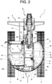
- An operation section 10 is provided on the swivel frame 7. Furthermore, a prime mover section including an engine 12 as a drive source is disposed on a rear portion on the swivel frame 7. On a right side of the operation section 10, a tank accommodation section 13 accommodating a fuel tank 14 and a hydraulic oil tank 15 is disposed (refer to FIG. 2 ).
- the operation section 10 is used to drive and operate the traveling device 2, the excavation device 3, and the soil removal device 4, and is disposed in a cabin 16 installed on the swivel frame 7.
- the cabin 16 has a frame that forms an outline thereof and a plurality of window sections made of a transparent member, such as glass, and is configured as a whole in a substantially box shape.
- the cabin 16 has, in a left side surface portion, an openable door 16a that opens and closes an entrance for an operator to the operation section 10.
- a driver's seat 17 is disposed on a driver's seat support base disposed on a floor portion.
- a traveling manipulation unit such as a traveling lever, a work manipulation unit, such as a work manipulation lever for operating work sections, such as the excavation device 3 and the soil removal device 4, an operation panel unit having various manipulation units, such as switches, and the like are disposed near the driver's seat 17.
- a left side work manipulation lever 18 is disposed on a left side of the driver's seat 17, and a right work operation lever 19 is disposed on a right side of the driver's seat 17 (refer to FIG. 2 ).
- the excavation device 3 is operated by the right and left manipulation levers.
- a base end portion of the excavation device 3 is mounted on a laterally-center portion of a front end of the swivel frame 7.
- the excavation device 3 has a boom 21 that constitutes a base end portion thereof, an arm 22 that is coupled to a tip end side of the boom 21, and a bucket 23 that is attached to a tip end portion of the arm 22.
- the excavation device 3 has a boom cylinder 24 that rotates the boom 21, an arm cylinder 25 that rotates the arm 22, and a bucket cylinder 26 that rotates the bucket 23.
- the base end portion of the boom 21 is supported by a boom support bracket 27.
- the boom support bracket 27 is supported by a bracket attachment section 28 protruding from a central portion in the lateral direction of a front end of the swivel frame 7 via a swing shaft with a vertical direction as a rotation axis direction.
- the excavation device 3 is disposed to swing to the right and left about the swing shaft with respect to the swivel frame 7 by an expansion and contraction movement of a swing cylinder 29 disposed between the boom support bracket 27 and the swivel frame 7.
- the boom cylinder 24, the arm cylinder 25, and the bucket cylinder 26 that are included in the excavation device 3 and the swing cylinder 29 that swings the excavation device 3 are each a hydraulic cylinder actuated by pressure oil discharged by a hydraulic pump 35.
- the soil removal device 4 is attached to a front side of the machine body frame 6.
- the soil removal device 4 has a support frame 31 that includes a pair of right and left arms, each of which extends in a front-rear direction between the right and left traveling sections 5, a blade 32 as a soil removal plate disposed on a tip end side of the support frame 31, and a blade cylinder 33 that lifts/lowers the blade 32 via the support frame 31.
- the blade cylinder 33 is a hydraulic cylinder operated by pressure oil discharged from the hydraulic pump 35.
- the support frame 31 is attached to the machine body frame 6 so as to be lifted and lowered in a rotatable manner, by having a rear end portion of the right and left arms supported in a rotatable manner by a support bracket disposed in a front portion of the machine body frame 6 with the lateral direction as a rotation axis direction.
- the blade 32 is installed in a state of being supported by a front end portion of the support frame 31.
- the blade cylinder 33 is disposed in a state of being hung in the front-rear direction between the machine body frame 6 and a back side of the blade 32.
- the excavation work machine 1 includes a lower traveling body, which is configured to include the machine body frame 6 and the traveling sections 5 supported on both the left and right sides of the machine body frame 6, and an upper swivel body mounted on the lower traveling body in a swiveling available manner.
- the upper swivel body includes the swivel frame 7, and the operation section 10, the engine 12, and the tank accommodation section 13 disposed on the swivel frame 7.
- a counterweight 41 is disposed in a rear lower portion of the swivel frame 7.
- a hood 42 is disposed on an upper side of the counterweight 41 so as to be openable and closable.
- the hood 42 constitutes a cover portion that covers a rear side of the swivel frame 7.
- an operator who is seated on the driver's seat 17 properly operates the traveling lever, the work manipulation lever, or the like, to perform a desired action or a desired work.
- the traveling lever when the traveling lever is operated, the traveling device 2 travels straight forward and backward or turns right and left by operating the right and left traveling sections 5.
- the work operation lever when the work operation lever is operated, the excavation work by the excavation device 3, or the soil removal work or ground leveling work by the soil removal device 4 is performed.
- the tank accommodation section 13 is disposed in a portion of a right region on the base plate 40.
- the base plate 40 is a plate-like frame member horizontally disposed, and forms a bottom surface portion of the swivel frame 7.
- the tank accommodation section 13 is configured such that the fuel tank 14, the hydraulic oil tank 15, and the like are accommodated in a tank chamber 20 sectioned on the base plate 40.
- the tank chamber 20 is sectioned from a portion on a center side in the lateral direction on the base plate 40 by a bulkhead portion including a portion of a vertical plate 43 disposed on the base plate 40.
- the rear side of the tank chamber 20 is spatially continuous with an engine room 30 that accommodates the engine 12 disposed at a rear portion on the base plate 40.
- An intermediate portion in the lateral direction on a rear side of the engine room 30 is covered with a counterweight 41 and the hood 42.
- the cabin 16 is disposed on a left side of the tank chamber 20 on the swivel frame 7.
- a portion on the right side of the vertical plate 43 on the base plate 40 is covered with a plurality of exterior covers which are covering members so that the tank chamber 20 serving as an accommodation space is formed.
- Each of the plurality of exterior covers has a shape and a size corresponding to a shape of the swivel frame 7 and the arrangement of the configurations on the swivel frame 7.
- the tank accommodation section 13 has, as the exterior covers, a right rear cover 51 that covers a right lateral rear portion of the tank chamber 20, a right front cover 52 that covers a right lateral front portion of the tank chamber 20, a lower right cover 53 that covers a right lower portion of the tank chamber 20, and a front cover 54 that covers a front portion of the tank chamber 20. These covers are, for example, metal covers.
- the tank accommodation section 13 further has an upper surface cover 55 that is a cover member that covers an upper side of the tank chamber 20 as an exterior cover.
- the upper surface cover 55 is a resin cover, for example, and is disposed so as to be openable and closable.
- the fuel tank 14 is disposed on a front portion, and the hydraulic oil tank 15 is disposed on a rear side of the fuel tank 14.
- the fuel tank 14 is a fuel oil tank that stores fuel oil to be supplied to the engine 12.
- the hydraulic oil tank 15 stores hydraulic oil for actuating various hydraulic actuators included in the excavation work machine 1.
- the various hydraulic actuators that are actuated by receiving supply of pressure oil from the hydraulic oil include hydraulic cylinders, such as the boom cylinder 24, the arm cylinder 25, the bucket cylinder 26, and the swing cylinder 29, as well as the traveling hydraulic motor 11 and the swivel motor.
- the hydraulic oil tank 15 is disposed behind the fuel tank 14, and is located at a substantially central portion in the front-rear direction in the tank chamber 20.
- the fuel tank 14 and the hydraulic oil tank 15 are mounted on and supported by the base plate 40.
- the fuel tank 14 and the hydraulic oil tank 15 are disposed adjacent to each other in the front-rear direction.
- a control valve 56 is disposed adjacent to the hydraulic oil tank 15 on a right side of the hydraulic oil tank 15.
- the control valve 56 is a device for controlling a flow of the pressure oil supplied from the hydraulic oil tank 15 to the plurality of hydraulic actuators by driving the hydraulic pump 35. By controlling supply of the pressure oil to the individual hydraulic actuators, an operation of the excavation device 3, a traveling operation of the traveling device 2, and the like are performed.
- a heat exchanger 60 and the engine 12 are disposed in the engine room 30 connected to the rear side of the tank chamber 20.
- the heat exchanger 60 is disposed on a right side, which is one side of the engine 12 in the lateral direction.
- the heat exchanger 60 is a device configuration having a heat exchange function for cooling the engine 12, and includes a radiator 61, an oil cooler 62, and a fan 63.
- the radiator 61 is a device for cooling cooling water of the engine 12.
- the oil cooler 62 is a device for cooling oil (hydraulic oil) pumped by the hydraulic pump 35.
- Each of the radiator 61 and the oil cooler 62 has a substantially cuboid outer shape so as to have a substantially rectangular shape in a plan view. In the plan view, the radiator 61 and the oil cooler 62 are arranged side by side in the front-rear direction, with the radiator 61 on the rear side and the oil cooler 62 on the front side, in a direction in which a longitudinal direction is perpendicular or substantially perpendicular to an axial direction of an output shaft 65 of the engine 12.
- the fan 63 is a cooling fan that rotates in conjunction with the engine 12, and sends air toward the engine 12.
- the fan 63 is disposed between a right side surface portion of the engine 12 and the radiator 61 and the oil cooler 62. Outside air for cooling is taken into the engine room 30 through a plurality of opening portions 51a (refer to FIG. 4 ) formed in the right rear cover 51 by the fan 63 so that the radiator 61, the oil cooler 62, and the like are cooled.
- the engine 12 is installed in a rear portion of the base plate 40 with the axial direction of the output shaft 65 corresponding to substantially the lateral direction or corresponding to the lateral direction. That is, the engine 12 is transversely disposed and mounted such that the axial direction of the output shaft 65 substantially coincides with or coincides with the lateral direction of the machine body.
- the engine 12 is transversely disposed such that the axial direction of the output shaft 65 is inclined by approximately 5 degrees to 8 degrees in a counterclockwise direction from the lateral direction in the plan view.
- the engine 12 is disposed in a state of being supported in a vibration-damping manner at a plurality of positions via a vibration-damping member 66 and the like with respect to a predetermined engine support portion disposed on the base plate 40.
- the output shaft 65 of the engine 12 protrudes to the right side, which is one side in the lateral direction of the machine body.
- the output shaft 65 is located at a lower portion of a right side surface of the engine 12 substantially at the center in the front-rear direction (refer to FIG. 5 ).
- the engine 12 is a diesel engine that receives fuel supplied from the fuel tank 14.
- the hydraulic pump 35 is disposed on a left side, which is the other side of the engine 12 in the lateral direction. That is, the hydraulic pump 35 is disposed on a side opposite to the protruding side of the output shaft 65 in the axial direction of the output shaft 65 of the engine 12.
- a rotation shaft of the hydraulic pump 35 is connected to a drive shaft of the engine 12 via a coupling.
- the hydraulic pump 35 is driven by the rotation of the drive shaft of the engine 12, and feeds the hydraulic oil in the hydraulic oil tank 15 to the various hydraulic actuators via the control valve 56.
- An exhaust gas purification device 70 for purifying exhaust gas discharged from the engine 12 is disposed for the engine 12.
- the exhaust gas purification device 70 is an example of an exhaust treatment device that is disposed above the engine 12 and treats exhaust gas discharged from the engine 12. Combustion gas generated in a combustion chamber of the engine 12 is discharged out of the engine room 30 through the exhaust gas purification device 70.
- the exhaust gas purification device 70 includes a DPF case 71, which is a diesel particulate filter case, as a cylindrical filter case into which the exhaust gas discharged from the engine 12 is introduced.
- the exhaust gas purification device 70 introduces exhaust gas discharged from the engine 12 into the DPF case 71 and removes particulate matter, such as soot contained in the exhaust gas, thereby purifying the exhaust gas.
- the DPF case 71 has a diesel oxidation catalyst and a soot filter in the case.
- the diesel oxidation catalyst is an oxidation catalyst, such as platinum, that generates nitrogen dioxide (NO2).
- the soot filter has a honeycomb structure that continuously oxidizes and removes trapped particulate matter at a relatively low temperature.
- the diesel oxidation catalyst and the soot filter are arranged in series with respect to a flow of the exhaust gas, with the diesel oxidation catalyst on an upstream side and the soot filter on a downstream side.
- the diesel oxidation catalyst and the soot filter remove the particulate matter mainly including black smoke in the exhaust gas of the engine 12 passing through the DPF case 71, and reduce carbon monoxide (CO) and hydrocarbon (HC) in the exhaust gas.
- the DPF case 71 is configured as a substantially cylindrical case.
- a longitudinal direction (cylinder axis direction) of a substantially cylindrical outer shape corresponds to a direction of the flow of the exhaust gas in the case.
- the DPF case 71 is disposed in a direction in which the longitudinal direction thereof is the front-rear direction or a substantially front-rear direction of the machine body.
- the DPF case 71 is disposed such that the longitudinal direction thereof is orthogonal to the axial direction of the output shaft 65 of the engine 12 in the plan view.
- a mounting plate 71c that is removed when a filter inside the DPF case 71 is replaced is disposed on an end surface portion on a rear side of the DPF case 71. The filter in the DPF case 71 can be removed by removing the mounting plate 71c.
- the DPF case 71 is disposed above the engine 12.
- the DPF case 71 has substantially the same size as the engine 12 in the front-rear direction, and is disposed such that the entire DPF case 71 is substantially positioned above the engine 12.
- the DPF case 71 is disposed above a right portion of the engine 12 in the lateral direction.
- the DPF case 71 is fixed to and supported by the engine 12 at two front and rear positions by means of a front support stay 75 and a rear support stay 76, respectively.
- the front support stay 75 is fixed to a front portion of an upper right portion of the engine 12, protrudes upward from the engine 12, supports a front portion of the DPF case 71 from below, and holds the front portion of the DPF case 71 together with a holding belt 77 extending along an outer peripheral surface of the DPF case 71.
- the rear support stay 76 is fixed to a rear portion of the upper right portion of the engine 12, protrudes upward from the engine 12, and is fixed to a lower portion of a flange portion 71a disposed on a rear portion of the DPF case 71 by bolts or the like, thereby supporting the rear portion of the DPF case 71 from below.
- One end side (downstream side) of an exhaust pipe 72 that discharges exhaust gas from the engine 12 is communicatively coupled to the DPF case 71.
- the DPF case 71 is coupled to one end of the exhaust pipe 72 on a left side of a front portion thereof.
- the other end side (upstream side) of the exhaust pipe 72 is communicatively coupled to an exhaust gas outlet side of a turbocharger (not illustrated) disposed on an exhaust manifold constituting an exhaust gas outlet portion in the engine 12.
- Exhaust gas in the engine 12 is introduced into the DPF case 71 through the exhaust pipe 72.
- An outlet pipe 73 for discharging the exhaust gas in the DPF case 71 is disposed on a rear portion of the DPF case 71.
- the outlet pipe 73 protrudes upward from an upper side of the DPF case 71.
- the outlet pipe 73 penetrates an upper surface portion 42a of the hood 42 and protrudes upward from the upper surface portion 42a.
- a tail pipe 74 constituting a discharge pipe portion of the exhaust gas purification device 70 together with the outlet pipe 73 is attached to the upper surface portion 42a of the hood 42.
- the excavation work machine 1 includes, as devices disposed near the engine 12, an alternator 81 driven by rotational power of the output shaft 65 of the engine 12 and a compressor 82 driven by the rotational power of the output shaft 65. Both the alternator 81 and the compressor 82 are disposed on a right side surface portion which is a side surface portion on the output shaft 65 side of the engine 12.
- the alternator 81 is driven by the power of the engine 12 to generate and output electric power.
- the alternator 81 is used as a power source or a generator for storing electricity in a battery.
- the compressor 82 is used for an air conditioning unit included in the excavation work machine 1, and is driven by the power of the engine 12 to compress air conditioning gas (refrigerant).
- the air for air-conditioning generated by the air conditioning unit is supplied in a compression manner through a duct (not illustrated), and is blown out from a plurality of air outlets provided in the cabin 16.
- the air conditioning unit is disposed below the driver's seat 17.
- the alternator 81 is driven by the rotational power of the output shaft 65 of the engine 12 transmitted by a first belt transmission mechanism 91.
- the first belt transmission mechanism 91 includes an output pulley 93 attached to the output shaft 65, an alternator input pulley 94 disposed on the alternator 81, and a first belt 95 wound around these pulleys.
- the output pulley 93 is fixed to the output shaft 65, and rotates integrally with the output shaft 65 with its rotation shaft direction aligned with the axial direction of the output shaft 65.
- the output pulley 93 is a so-called double pulley and has two outer circumferential grooves adjacent to each other in the rotation shaft direction.
- the first belt 95 is engaged with the groove on the right side (front side in FIG. 5 ) of the output pulley 93.
- the alternator input pulley 94 is disposed on a right side of the alternator 81, and is fixed to the rotation shaft 81a of the alternator 81 having an axis direction parallel to the output shaft 65.
- a rotation shaft direction of the alternator input pulley 94 is aligned with an axial direction of the rotation shaft 81a of the alternator 81, and the alternator input pulley 94 rotates integrally with the rotation shaft 81a.
- a fan pulley 97 for rotationally driving the fan 63 is disposed over the output pulley 93.
- the fan pulley 97 is disposed on a right side surface portion of the engine 12 so as to be rotatable with respect to a shaft support portion disposed over the output shaft 65 with an axial direction parallel to the output shaft 65.
- the fan pulley 97 constitutes the first belt transmission mechanism 91 together with the output pulley 93 and the alternator input pulley 94 around which the first belt 95 is wound, and receives the rotational power of the output shaft 65.
- the fan 63 is disposed so as to rotate integrally with the fan pulley 97, and rotates in conjunction with the rotation of the output shaft 65.
- the compressor 82 is driven when receiving transmission of the rotational power of the output shaft 65 of the engine 12 transmitted by a second belt transmission mechanism 92.
- the second belt transmission mechanism 92 includes the output pulley 93 attached to the output shaft 65, a compressor input pulley 98 disposed on the compressor 82, and a second belt 99 wound around these pulleys.
- the second belt 99 is engaged with the groove on the left side (depth side in FIG. 5 ) of the output pulley 93. That is, in the axial direction of the output shaft 65, the compressor input pulley 98 is positioned on the left side with respect to the alternator input pulley 94, and the second belt 99 is disposed at a position shifted to the left with respect to the first belt 95.
- the compressor input pulley 98 is disposed on a right side of the compressor 82, and is fixed to a rotation shaft 82a of the compressor 82 with an axis direction in parallel to the output shaft 65.
- a rotation shaft direction of the compressor input pulley 98 is aligned with an axial direction of the rotation shaft 82a of the compressor 82, and the compressor input pulley 98 rotates integrally with the rotation shaft 82a.
- the alternator 81 is disposed at a position behind the engine 12 and below the exhaust gas purification device 70.
- the alternator 81 is disposed on a right side of the engine 12 and on a rear side of an upper portion of the engine 12.
- the alternator 81 is disposed at a position rearward of the output shaft 65 located substantially at the center in the front-rear direction.
- the alternator 81 is entirely located rearward of the output pulley 93 in the front-rear direction.
- the alternator 81 is positioned above the fan pulley 97 in the vertical direction, and is disposed at a position obliquely rearward and upward with respect to the fan pulley 97.
- the alternator 81 is disposed below a rear end portion of the DPF case 71 in the front-rear direction. Specifically, the alternator 81 is disposed so as to be entirely or substantially entirely positioned below a portion of the DPF case 71 on the rear side of the flange portion 71a on the upper side of which the outlet pipe 73 is disposed.
- the compressor 82 is disposed below the alternator 81.
- the alternator 81 and the compressor 82 have substantially cylindrical outer shapes whose relative sizes with respect to the engine 12 are substantially the same as each other.
- the alternator 81 is slightly larger than the compressor 82.
- a height position of an upper end of the compressor 82 is positioned lower than a height position of a lower end of the alternator 81 in the vertical direction.
- the compressor 82 is positioned behind the alternator 81 in the machine body. That is, the compressor 82 located below the alternator 81 is disposed on the rear side of the alternator 81 in the front-rear direction. Therefore, the rotation shaft 82a of the compressor 82 is positioned rearward of the rotation shaft 81a of the alternator 81 in the front-rear direction.
- the compressor 82 is disposed such that a substantially front half of the compressor 82 overlaps with a substantially rear half of the alternator 81 in the front-rear direction (refer to FIG. 5 ).
- a rear portion of the compressor 82 disposed as described above is positioned rearward of the DPF case 71 in the front-rear direction.
- the alternator 81 and the compressor 82 are disposed so as to substantially entirely overlap with each other in the lateral direction (refer to FIG. 6 ). Therefore, the compressor 82 is disposed such that substantially the front half of the compressor 82 overlaps with a rear portion of the alternator 81 in the plan view.
- the alternator 81 and the compressor 82 which are disposed so as to entirely overlap each other in the lateral direction, are disposed so as to entirely or substantially entirely overlap the DPF case 71 in the lateral direction except for a right end portion. That is, the alternator 81 and the compressor 82 are positioned entirely or substantially entirely below the DPF case 71 in the lateral direction. Therefore, in the rear view, the DPF case 71, the alternator 81, and the compressor 82 are vertically arranged along the vertical direction (refer to FIG. 6 ). In this embodiment, the DPF case 71, the alternator 81, and the compressor 82 are arranged at substantially equal intervals in the vertical direction.
- the alternator 81 is disposed in a state in which a lower end side, which is one end side, is supported in a rotatable manner with respect to the engine 12, and an upper end side, which is the other end side, is fixed and supported in a position changeable manner with respect to an upper support bracket 100, which is a support bracket disposed near the engine 12, so as to allow rotation of the alternator 81. That is, the lower side of the alternator 81 is supported in a rotatable manner by the engine 12 as a rotation support portion, and the upper side of the alternator 81 is movably supported by the engine 12 as a movable support portion.
- the lower rotation support portion of the alternator 81 is supported by a lower support bracket 101, which is attached to the right side surface portion of the engine 12, so as to be rotatable about a rotation axis direction that coincides with (is parallel to) the axial direction of the rotation shaft 81a.
- the lower support bracket 101 includes a fixing surface portion 101a extending along the right side surface portion of the engine 12, and a horizontal support surface portion 101b bent leftward at a right angle from an upper end portion of the fixing surface portion 101a.
- the lower support bracket 101 fixes the fixing surface portion 101a to the right side surface portion of the engine 12 at a plurality of positions by fixing bolts 102.
- the lower support bracket 101 has a support cylindrical portion 103, on a rear side of the support surface portion 101b, which is a cylindrical portion whose both ends are opened with a direction coinciding with the axial direction of the rotation shaft 81a as a central axis direction.
- the support cylindrical portion 103 is fixed to the support surface portion 101b by welding or the like.
- the alternator 81 has two lower support projecting pieces 81b opposed to each other in the axial direction of the rotation shaft 81a on a lower end side of the housing forming the exterior thereof.
- the two lower support projecting pieces 81b are disposed on opposite sides in the axial direction of the rotation shaft 81a of the alternator 81 at an interval in the axial direction of the rotation shaft 81a on a lower side of a cylindrical main body portion of the housing of the alternator 81.
- the support cylindrical portion 103 is positioned between the left and right lower support projecting pieces 81b, and a lower support bolt 104 penetrating the left and right lower support projecting pieces 81b and the support cylindrical portion 103 is supported in a rotatable manner as a support shaft.
- the lower support bolt 104 is inserted from a side near the right lower support projecting piece 81b, and a distal end portion thereof is projected leftward from the left lower support projecting piece 81b and is screwed into a nut 105, thereby fixing the alternator 81.
- a cylindrical collar 106 through which the lower support bolt 104 penetrates is interposed between the support cylindrical portion 103 and the left lower support projecting piece 81b.
- the alternator 81 is supported by an upper movable support portion so as to be movable with respect to the upper support bracket 100.
- the upper support bracket 100 extends toward the rear of the machine body from the rear support stay 76, which is a support member that supports the DPF case 71 of the exhaust gas purification device 70 with respect to the engine 12.
- the rear support stay 76 includes a fixing surface portion 76a extending along the right side surface portion of the engine 12 and a support surface portion 76b which is bent leftward at a right angle from a rear side of an upper portion of the fixing surface portion 76a and whose plate thickness direction is substantially the front-rear direction.
- a lower portion of the fixing surface portion 76a is fixed to the right side surface portion of the engine 12 at a plurality of locations by fixing bolts 110, and an upper portion of the fixing surface portion 76a extends above the engine 12.
- the support surface portion 76b serves as a portion to which the flange portion 71a of the DPF case 71 is fixed by inserting fixing tool, such as bolts 111.
- the bolts 111 penetrate the support surface portion 76b and the flange portion 71a and are screwed into nuts 112.
- the upper support bracket 100 is fixed to the fixing surface portion 76a of the rear support stay 76 and extends rearward.
- the upper support bracket 100 includes a fixing surface portion 121 that is a portion fixed to the rear support stay 76, an arm portion 122 extending rearward from the fixing surface portion 121, and a locking surface portion 123 extending rightward from a rear end portion of the arm portion 122.
- the upper support bracket 100 is fixed to the rear support stay 76 at a plurality of positions by fixing bolts 124 in a state in which the fixing surface portion 121 is superimposed on a right side of an upper portion of the fixing surface portion 76a of the rear support stay 76.
- the arm portion 122 is a plate-like portion whose plate thickness direction is substantially the lateral direction, and extends horizontally substantially in the front-rear direction.
- the locking surface portion 123 is a plate-like portion that forms a substantially right angle with the arm portion 122 in a plan view.
- the alternator 81 has an upper support projecting piece 81c on an upper end side of the housing.
- the upper support projecting piece 81c is disposed on a position opposite to the lower support projecting piece 81b with respect to the rotation shaft 81a as a center (i.e., on a substantially point-symmetrical position).
- the upper support projecting piece 81c is disposed on substantially the same position as the right lower support projecting piece 81b in the axial direction of the rotation shaft 81a.
- the alternator 81 is supported by an upper support bolt 132 as a support shaft which penetrates a substantially cuboid guide block 131 disposed on a right side of the arm portion 122 and the arm portion 122 and is screwed into the upper support projecting piece 81c.
- a guide hole 122a extending in an arc shape as viewed in the axial direction of the rotation shaft 81a is formed as a hole portion through which the upper support bolt 132 penetrates.
- the guide hole 122a has a shape along an arc centered on an axial center position of the lower support bolt 104, which is a center of rotation of the rotation support portion of the alternator 81, and allows the upper support bolt 132 to move with respect to the upper support bracket 100 as the alternator 81 rotates.
- the guide block 131 has a lower portion through which the upper support bolt 132 penetrates and an upper portion through which the guide bolt 133 penetrates.
- the guide bolt 133 is provided along a direction orthogonal to the axial direction of the upper support bolt 132 in the plan view, penetrates the locking surface portion 123 by a recessed portion 123a which is formed in the locking surface portion 123 and whose upper side is opened, and locks a head portion 133a to a rear side of the locking surface portion 123.
- a positioning nut 134 is screwed onto the guide bolt 133 on a rear side of the guide block 131.
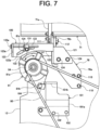
- the alternator 81 According to the support configuration of the alternator 81 having the above-described configuration, by loosening the fastening of the rotation support portion by the lower support bolt 104, the alternator 81 becomes rotatable about the lower support bolt 104 serving as a shaft. In this state, the guide block 131 on the guide bolt 133 is moved by operating the guide bolt 133 in the movable support portion so that a position of the alternator 81 in the rotational direction (refer to the arrow Al in FIG. 7 ) around the lower support bolt 104 is adjusted.
- Tension of the first belt 95 is adjusted by adjusting the rotational position of the alternator 81.
- an adjustable angular range of the rotation of the alternator 81 is, for example, approximately 20 degrees to 30 degrees.
- a lower side of the compressor 82 is supported in a rotatable manner as a rotation support portion with respect to the engine 12, and an upper side of the compressor 82 is movably supported as a movable support portion.
- the compressor 82 has two lower support projecting pieces 82b projecting from the lower side of the housing forming an exterior of the compressor 82 (refer to FIGS. 6 and 10 ).
- the lower support projecting pieces 82b are fastened and fixed by bolts 142 to respective side surface portions 141a of the lower support bracket 141 formed in a substantially "U" shape in a rear view by the lower surface portion 141a and right and left side surface portions 141b.
- the lower support bracket 141 has a support surface portion 141c formed by extending the right side surface portion 141b downward, and is supported in a rotatable manner by a support plate portion 171a of a support stay 171 disposed on the lower side of the lower support bracket 141 with the lower support bolt 172 as a support shaft.
- the axial direction of the center shaft of the lower support bolt 172 which serves as the rotational axis of the lower support bracket 141, coincides with (is parallel to) the axial direction of the rotation shaft 82a.
- the lower support bolt 172 penetrates the support surface portion 141c from the left side and is screwed into the support plate portion 171a, and fixes the lower support bracket 141 to the support stay 171.
- a portion on the left side from the support surface portion 141c is extended as a hexagonal columnar manipulation unit 172a having a hexagonal cross-sectional shape, and an end portion on the right side is screwed to the support plate portion 171a as a screw portion.
- the support stay 171 is fixedly provided on a substantially "L"-shaped mounting bracket 140 which is a predetermined support member disposed on a lower portion of the rear side of the engine 12 (refer to FIG. 5 ).
- the attachment bracket 140 is a member to which the vibration-damping member 66 on the right rear side is attached.
- the upper movable support portion of the compressor 82 has an upper support projecting piece 82c projecting upward from the housing (refer to FIG. 10 ).
- the compressor 82 is supported by an upper support bracket 143, which is fixed to a lower support bracket 101 supporting the lower side of the alternator 81 and extends rearward, by an upper support bolt 144 penetrating the upper support bracket 143.
- the upper support bracket 143 is fixed to the lower support bracket 101 by a fixing bolt 145 in a state in which a front end portion thereof is overlapped on the left side with respect to a portion on the rear side of the lower portion of the fixing surface portion 101a of the lower support bracket 101.
- the upper support bolt 144 penetrates the support arm 146 fixed to the upper support bracket 143, penetrates the arc-shaped guide hole 143a, and is screwed into the upper support projecting piece 82c.
- the guide hole 143a has a shape along an arc around an axial center position of the lower support bolt 172, which is a rotation center of the rotation support portion of the compressor 82, and allows the upper support bolt 144 to move with respect to the upper support bracket 143 as the compressor 82 rotates.
- the support arm 146 has an upper portion that extends to the left side (a back side in FIG. 10 ) along the axial direction of the upper support bolt 144, and penetrates the guide bolt 147 on the left side of the upper support bracket 143.
- the guide bolt 147 is disposed in parallel to the upper support bracket 143.
- the guide bolt 147 is disposed along a direction orthogonal to the axial direction of the upper support bolt 144 in the plan view, penetrates a locking surface portion 148 extending from the rear end portion of the upper support bracket 143 leftward, and has a head portion 147a locked to the rear side of the locking surface portion 148.
- the guide bolt 147 penetrates the locking surface portion 148 by a recessed portion 148a (refer to the recessed portion 123a in FIG. 8 ) which is formed in the locking surface portion 148 and is opened upward.
- a positioning nut 149 is screwed onto the guide bolt 147 on the rear side of the support arm 146.
- the lower support bracket 141 and the compressor 82 supported by the lower support bracket 141 may integrally rotate about the lower support bolt 172.
- the support arm 146 on the guide bolt 147 is moved by an operation performed on the guide bolt 147 in the movable support portion, and the positions of the compressor 82 and the lower support bracket 141 in the rotation direction (refer to an arrow A2 in FIG. 10 ) around the lower support bolt 172 are adjusted.
- Tension of the second belt 99 is adjusted by adjusting the rotational position of the compressor 82.
- an adjustable angular range of the rotation of the compressor 82 is, for example, approximately 20 degrees to 30 degrees.
- the excavation work machine 1 includes the counterweight 41 as a shielding portion and the hood 42 as a cover body in a rear portion of the upper swivel body.
- the counterweight 41 and the hood 42 are configured to be bilaterally symmetrical or substantially bilaterally symmetrical.
- the counterweight 41 has an opening portion 150 that covers the engine room 30 from the rear side and exposes the engine room 30 to the outside.
- the counterweight 41 includes a shielding main body portion 151 having a substantially trapezoidal outer shape in a rear view of the machine body, and projecting portions 152 extending upward from both left and right ends of the shielding main body portion 151 and forming the opening portion 150 together with the shielding main body portion 151.
- a right edge portion of the shielding main body portion 151 and a right edge portion of the right projecting portion 152R which is the right projecting portion 152 are linearly continued to each other to form a right edge portion 154 of the counterweight 41.
- the right edge portion 154 of the counterweight 41 abuts on an edge portion 51b on the rear side of the right rear cover 51. Furthermore, a lower end portion of the right edge portion 154 of the counterweight 41 abuts on the rear edge portion 53b of the lower right cover 53.
- a right edge portion of the shielding main body portion 151 and a right edge portion of the left projecting portion 152L which is the left projecting portion 152 are linearly continued to each other to form a left edge portion 155 of the counterweight 41.
- the left edge portion 155 of the counterweight 41 abuts on an edge portion 156b on the rear side of a left rear cover 156 which is an exterior cover disposed on the left rear side of the cabin 16.
- a lower edge portion of the left edge portion 155 of the counterweight 41 abuts on a rear edge portion 157b of the lower left cover 157 that is an exterior cover.
- the lower left cover 157 is disposed so as to be continuous with the lower side of the left side surface portion of the cabin 16, and is configured so as to be substantially bilaterally symmetrical to the lower right cover 53.
- a lower edge portion of the shielding main body portion 151 forming a lower portion of the counterweight 41 serves as a lower edge portion 158 of the counterweight 41.
- the lower edge portion 158 of the counterweight 41 is horizontal and extends along the base plate 40.
- the right edge portion 154 and the left edge portion 155 are inclined from the lower side to the upper side such that intervals therebetween (intervals in the lateral direction) are gradually narrowed, and the counterweight 41 has an outer shape along a substantially trapezoidal shape having the lower edge portion 158 as a base portion as a whole.
- the opening portion 150 is formed by the shielding main body portion 151 and the left and right projecting portions 152. That is, the opening portion 150 is formed to have a substantially "U" shape in the rear view by an upper edge portion of the shielding main body portion 151, a left edge portion of the right projecting portion 152R, and a right edge portion of the left projecting portion 152L.
- the opening portion 150 allows the engine room 30 to communicate with the outside in a state where the hood 42 is opened.
- the opening portion 150 opens most of a substantially upper half portion of the counterweight 41 in the vertical direction.
- the upper portion of the engine 12 and the exhaust gas purification device 70 are positioned within the opening portion 150.
- the shielding main body portion 151 covers the lower portion of the engine 12 from the rear side, and the right and left projecting portions 152 are positioned on the right and left sides of the upper portion of the engine 12 in the rear view.
- the hood 42 is disposed so as to cover the opening portion 150 of the counterweight 41 in an openable and closable manner. As shown in FIG. 11 , the hood 42 has an upper surface portion 42a and a covering main body portion 42b which is a rear surface portion and which covers substantially the entire opening portion 150.
- the hood 42 is disposed so as to be rotatable about a hinge (not illustrated) disposed at a front portion of the upper surface portion 42a with the machine body lateral direction as a rotation axis direction. When the hood 42 is rotated upward from a closed state, the opening portion 150 is entirely opened (refer to an arrow B1 in FIG. 1 ).
- the hood 42 is disposed so as to be opened to a rotational position at which at least the lower end of the hood 42 is positioned above the upper surface portion 42a of the hood 42 in a closed state. Note that, in FIG. 1 , the hood 42 in an open state is indicated by a two dot chain line.
- the hood 42 is fitted to a step portion 159 formed around the opening portion 150 along an outer shape of the hood 42 in the counterweight 41, and constitutes a rear wall surface portion integrated with the counterweight 41.
- the step portion 159 has a lower side portion 159a formed in a substantially V shape in the rear view along the lower edge portion of the covering main body portion 42b of the hood 42, and left and right inclined side portions 159b formed in an inclined shape along the left edge portion 155 and the right edge portion 154 of the right and left projecting portions 152, respectively, in the rear view along the right and left edge portions of the covering main body portion 42b.
- a seal member formed of rubber or the like and disposed along the stepped portion 159 is interposed between the counterweight 41 and the hood 42.
- the alternator 81 is disposed at a position where at least a part of the alternator 81 overlaps the opening range of the opening portion 150 in the rear view of the machine body. Specifically, as illustrated in FIG. 4 , the alternator 81 is located on the lower right side of the opening portion 150 in the rear view, and most of the upper side of the alternator 81 is located in the opening range of the opening portion 150. Specifically, the alternator 81 is disposed such that an intermediate portion of a right half portion of an upper edge portion of the shielding main body portion 151 is positioned at a lower portion in the rear view.
- a lower end portion of the alternator 81 is covered by the shielding main body portion 151 of the counterweight 41 in the rear view. Furthermore, a right end portion of the alternator 81 is covered by the shielding main body portion 151 and a shielding plate 160 attached to the counterweight 41 as described later in the rear view.
- the compressor 82 is disposed at a position where at least a portion of the compressor 82 overlaps the counterweight 41 in the rear view of the machine body.
- the compressor 82 is positioned below the alternator 81, and as illustrated in FIG. 4 , is disposed at a position where the entire compressor 82 overlaps the counterweight 41 in the rear view.
- the compressor 82 is positioned in front of a vertically intermediate portion of the right half portion of the shielding main body portion 151, and is disposed at a position where the entire compressor 82 is covered by the shielding main body portion 151 from the rear side.
- the exhaust gas purification device 70 is disposed such that the entire DPF case 71 is positioned within the opening range of the opening portion 150 in the rear view. Therefore, in a state where the hood 42 is opened, the entire DPF case 71 disposed with the mounting plate 71c facing the rear side is exposed from the opening portion 150.
- the counterweight 41 is includes the shielding plate 160 that covers a portion of the opening portion 150.
- the shielding plate 160 will be described with reference to FIGS. 4 and 12 to 14 .
- the shielding plate 160 is an example of a protection member which closes a part of the opening portion 150, and functions as a fan guard for the fan 63 which is partially exposed from the opening portion 150.
- the shielding plate 160 is detachably disposed on the counterweight 41.
- the shielding plate 160 is disposed such that at least a part thereof overlaps a space 170 (refer to FIG. 6 ) between the engine 12 and the fan 63 in the rear view of the machine body in the configuration in which the fan 63 disposed on the right side which is one side in the lateral direction of the engine 12 is disposed in the engine room 30.
- the shielding plate 160 is disposed on the right projecting portion 152R among the right and left projecting portions 152 included in the counterweight 41.
- the engine 12 is installed at a substantially central portion in the lateral direction of the machine body, and the fan 63 is disposed on the right side of the engine 12. Therefore, the fan 63 is disposed at a position on the right side in the engine room 30.
- the shielding plate 160 is attached to the right projecting portion 152R among the right left projecting portions 152 on the side where the fan 63 is located in the lateral direction.
- an upper end portion of the fan 63 is positioned in the vicinity of a corner portion on the lower right side formed by the shielding main body portion 151 and the right projecting portion 152R in the opening portion 150. That is, the fan 63 is disposed such that most of the lower side other than the upper end portion in the rear view is hidden by the shielding main body portion 151 of the counterweight 41. In addition, the fan 63 is positioned on the right side with respect to the right side surface portion of the engine 12 at a predetermined interval via the shaft support portion. Thus, the space 170 is present as a gap between the engine 12 and the fan 63 (refer to FIG. 6 ).
- the shielding plate 160 is disposed on the right projecting portion 152R located in the vicinity of the fan 63 in the rear view.
- the shielding plate 160 is provided so as to cover the portion between the engine 12 and the upper end portion of the fan 63 in the space 170 between the engine 12 and the fan 63 from the rear side. That is, the shielding plate 160 is disposed in the vicinity of a corner portion on the lower right side of the opening portion 150 formed by the shielding main body portion 151 and the right projecting portion 152R.
- the shielding plate 160 is disposed so as to cover a portion between the alternator 81 disposed on the upper right side of the engine 12 and the upper end portion of the fan 63 from the rear side.
- the shielding plate 160 is a plate-shaped member having a predetermined shape, and includes a shielding plate main body portion 161 which functions as a covering portion which partially closes a lower right portion of the opening portion 150, and a fixing surface portion 162 which is a fixing portion of the shielding plate 160 with respect to the counterweight 41.
- the fixing surface portion 162 is formed on a right side of the shielding plate main body portion 161. Therefore, in the shielding plate 160, the fixing surface portion 162 is fixed to the right projecting portion 152R, and the shielding plate main body portion 161 extends leftward from the right projecting portion 152R.
- the shielding plate main body portion 161 has a linear left edge end portion 161a along the vertical direction, and an inclined upper edge end portion 161b and a lower edge end portion 161c, and has a substantially trapezoidal shape with these edge end portions with the left edge end portion 161a side as a bottom side in the rear view. That is, the shielding plate main body portion 161 has a shape in which a size in the vertical direction is gradually increased from the right side to the left side as a covering shape for the opening portion 150.
- the fixing surface portion 162 is formed as a projecting piece having an outer shape along a rectangular shape whose longitudinal direction is the vertical direction from an intermediate portion in the vertical direction on the right side of the shielding plate main body portion 161.
- a shielding plate mounting portion 180 to which the shielding plate 160 is fixed is disposed on the right projecting portion 152R.
- the shielding plate attachment portion 180 is disposed on an inner side (left side) of a base portion of the right projecting portion 152R.
- the shielding plate attachment portion 180 is formed at a lower end portion of a protruding portion 181 formed on left and right inner sides (left side) of the right projecting portion 152R in the lateral direction.
- the protruding portion 181 protrudes to the left and right inner sides so as to narrow the opening portion 150 at a position on the back side (front side) with respect to a ridge portion 182 so as to form the inclined side portion 159b of the stepped portion 159 together with the right ridge portion 182 forming an upper portion of the right edge portion 154 of the counterweight 41 in the right projecting portion 152R.
- the protruding portion 181 of the right projecting portion 152R receives the hood 42 in the counterweight 41 together with the protruding portion 183 of the left projecting portion 152L.
- the left protruding portion 183 protrudes to the left and right inner sides (right side) so as to narrow the opening portion 150 at a position on the back side (front side) with respect to a ridge portion 184 so as to form the inclined side portion 159b of the stepped portion 159 together with the right ridge portion 184 forming an upper portion of the left edge portion 155 of the counterweight 41 in the left projecting portion 152L.
- the left protruding portion 183 is formed to be wider as a whole than the right protruding portion 181.
- the left and right protruding portions 181 and 183 are covered by the hood 42 in the closed state.
- the shielding plate mounting portion 180 is a rearward projecting portion having a rectangular shape whose longitudinal direction is the vertical direction, and forms a pedestal portion for mounting the shielding plate 160.
- the shielding plate attachment portion 180 has a flat support surface 180a that supports the fixing surface portion 162 of the shielding plate 160.
- the support surface 180a is a vertical flat surface facing rearward.
- the fixing surface portion 162 is fixed to the shielding plate mounting portion 180 at two upper and lower positions by mounting bolts 185.
- screw holes 180b into which the mounting bolts 185 are screwed are opened at two positions, that is, upper and lower positions, so as to face the support surface 180a.
- a hole portion 162a through which the mounting bolts 185 penetrates is formed in the fixing surface portion 162.
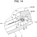
- the shielding plate main body portion 161 is inclined in a plan view so that the left edge end portion 161a of the shielding plate main body portion 161 is positioned on a left rear side with respect to the fixing surface portion 162 (refer to FIG. 14 ).
- the shielding plate main body portion 161 is inclined along the inclination of the shielding main body portion 151 of the counterweight 41 which has a curved shape protruding rearward in a plan view.
- the shielding plate 160 has a bent shape in a plan view formed by the shielding plate main body portion 161 and the fixing surface portion 162, and forms a linear ridge line portion 163 extending in the vertical direction. That is, the shielding plate 160 is a bent plate-like member having a constant thickness and formed by the shielding plate main body portion 161 and the fixing surface portion 162. An angle formed by the shielding plate main body portion 161 and the fixing surface portion 162 in the plan view is, for example, approximately 160 degrees.
- a recessed portion 186 that positions the shielding plate main body portion 161 of the shielding plate 160 is formed in the protruding portion 181 of the right projecting portion 152R.
- the recessed portion 186 is formed by cutting out a lower portion of the protruding portion 181 in the rear view, and has a substantially trapezoidal recessed shape along an outer shape of the shielding plate main body portion 161.
- the recessed portion 186 is formed so as to be entirely closed by the shielding plate main body portion 161 while forming a clearance with respect to each of the upper edge end portion 161b and the lower edge end portion 161c of the shielding plate main body portion 161 of the shielding plate 160 in the rear view.
- the recessed portion 186 forms a recessed opening portion which is closed by the shielding plate 160 in the opening portion 150 at the lower right corner portion of the opening portion 150. That is, in a state where the hood 42 is opened and the opening portion 150 is opened, the recessed portion 186 serves as an opening portion that allows the engine room 30 to communicate with the outside when the shielding plate 160 is removed. Therefore, the recessed portion 186 is formed so that a portion between the engine 12 and the upper end portion of the fan 63 in the space 170 between the engine 12 and the fan 63 overlaps with the opening range of the recessed portion 186 in the rear view.
- the recessed portion 186 secures a work space for maintenance in a state where the shielding plate 160 is removed. That is, the recessed portion 186 is opened to secure a space for accessing a maintenance target in the engine room 30. As the maintenance performed through the recessed portion 186, for example, the tension of the first belt 95 is adjusted by rotating the alternator 81 as described above.
- the excavation work machine 1 of this embodiment in the configuration including the exhaust gas purification device 70, it is possible to obtain favorable maintainability of devices, such as the alternator 81 disposed near the engine 12, and to efficiently dispose the devices in the engine room 30.
- the alternator 81 is disposed at a position behind the engine 12 and below the exhaust gas purification device 70. According to such a configuration, for example, as compared with a configuration in which the alternator 81 is disposed on the front side of the engine 12, the alternator 81 is disposed at a position easily accessible from the rear side of the machine body. Therefore, it is possible to obtain favorable maintainability of the alternator 81. In particular, since the rear side of the engine room 30 is opened by the opening portion 150 when the hood 42 is opened, the alternator 81 disposed on the rear side of the engine 12 is easily accessible and can be easily maintained.
- the exhaust gas purification device 70 which is relatively bulky and heavy, is disposed above the engine 12 on a side opposite to a side on which the hydraulic pump 35 is disposed, a well-balanced and efficient equipment layout can be achieved in the engine room 30.
- the hydraulic pump 35 which is a relatively small device is installed in a space on one of the left and right sides (left side) with respect to the engine 12 and the exhaust gas purification device 70 which are relatively bulky, and the operation section 10 in the cabin 16 is disposed on an upper front side of the installation space of the hydraulic pump 35.
- the space of the engine room 30 is limited. Therefore, according to the device layout in the engine room 30 according to the present embodiment, it is possible to effectively suppress the space of the operation section 10 from being reduced, and it is possible to easily balance the weight between the left and right sides of the machine body.
- the compressor 82 is disposed below the alternator 81 as the arrangement configuration of the devices included in the engine room 30.
- the compressor 82 is disposed at a position easily accessible from the rear side of the machine body. Therefore, it is possible to obtain favorable maintainability of the compressor 82.
- the compressor 82 disposed on the rear side of the engine 12 is easily accessible and can be easily maintained.
- the compressor 82 is positioned behind the alternator 81. With this configuration, the compressor 82 can be disposed at a more easily accessible position, and good maintainability can be obtained.
- the counterweight 41 having the opening portion 150 and the hood 42 for opening and closing the opening portion 150 are disposed as a configuration forming a rear wall portion of the engine room 30, the alternator 81 is disposed so that a part thereof is exposed from the opening portion 150, and the compressor 82 is disposed at a position where the whole thereof is covered by the counterweight 41.
- the alternator 81 and the compressor 82 can be disposed at a more easily accessible position, and good maintainability can be obtained for these devices.
- the cylindrical DPF case 71 is disposed above the engine 12 in a direction in which the central axis direction thereof is the front-rear direction or the substantially front-rear direction.
- the DPF case 71 is disposed at a position which is easily accessed from the rear side of the machine body, and thus it is possible to obtain favorable maintainability of the DPF case 71.
- the DPF case 71 is installed such that the mounting plate 71c faces the rear side, by opening the hood 42, it is possible to easily perform replacement work or the like of the filter of the DPF case 71 from the opening portion 150.
- the mounting plate 71c of the DPF case 71, the alternators 81, and the compressors 82 are arranged vertically in the rear view, these devices can be arranged in a concentrated manner, and the workability of the maintenance work can be improved.
- the DPF case 71 is disposed along the front-rear direction above the engine 12, it is possible to effectively use the space in the engine room 30, and it is possible to effectively reduce a situation in which a room of the operation section 10 is reduced by the space required in the engine room 30. As a result, the space of the operation section 10 is easily secured, and the comfort of the operation section 10 can be improved.
- the alternator 81 is supported in a rotatable manner to adjust the tension of the first belt 95.
- it is possible to easily perform an operation of adjusting the tension of the first belt 95 as a maintenance operation for the alternator 81 disposed at a position which is easily accessible from the rear side of the machine body, and it is possible to obtain favorable maintainability.
- the counterweight 41 has the shielding plate 160 disposed so as to shield the space between the engine 12 and the fan 63 from the rear side.
- the shielding plate 160 is attached to the right projecting portion 152R of the counterweight 41. With this configuration, the shielding plate 160 can be provided with a simple configuration without separately providing a support member of the shielding plate 160.
- the shielding plate 160 is disposed so as to close the recessed portion 186 formed in the protruding portion 181 disposed in the right projecting portion 152R.
- the shielding plate 160 is disposed so as to close the recessed portion 186 formed in the protruding portion 181 disposed in the right projecting portion 152R.
- the work machine according to the present disclosure described in the embodiment above is not limited to the above-mentioned embodiment, and various modes can be adopted to the extent within the scope of the gist of the present disclosure.
- the present technique may have the following configurations. Note that the configurations described below can be selected, omitted, and arbitrary combined.
Landscapes
- Engineering & Computer Science (AREA)
- General Engineering & Computer Science (AREA)
- Chemical & Material Sciences (AREA)
- Mining & Mineral Resources (AREA)
- Civil Engineering (AREA)
- Structural Engineering (AREA)
- Mechanical Engineering (AREA)
- Combustion & Propulsion (AREA)
- Chemical Kinetics & Catalysis (AREA)
- Health & Medical Sciences (AREA)
- Toxicology (AREA)
- Component Parts Of Construction Machinery (AREA)
Abstract
[Problem] In a configuration including an exhaust treatment device, it is possible to obtain favorable maintainability of devices, such as an alternator disposed near an engine, and to efficiently dispose the devices in an engine room.[Solution] A work machine includes an engine 12 having an output shaft projecting to one side in a lateral direction of a machine body, a hydraulic pump 35 disposed on the other side in the lateral direction of the engine 12, an exhaust gas purification device 70 disposed above the engine 12 and treating exhaust gas discharged from the engine 12, and an alternator 81 driven by rotational power of the output shaft. The alternator 81 is disposed at a position behind the engine 12 and below the exhaust gas purification device 70.
Description
- The present disclosure relates to a work machine including an alternator that is driven by power of an engine to generate electric power.
- In general, work machines including an alternator that is driven by power of an engine to generate electric power have been used (for example, refer to Patent Document 1).
- Patent Document 1 discloses a configuration of a backhoe, which is a type of work machine, in which an engine is mounted inside a hood having an opening/closing cover that can be opened rearward in a direction in which an axial direction of an output shaft is a lateral direction of a machine body, a compressor for an air conditioner is disposed on an upper portion of a side surface of the engine on an output shaft side, and the alternator is disposed at a position below the compressor and rearward of the output shaft. The configuration disclosed in Patent Document 1 is made to facilitate access to the alternator and the compressor from a rear side of the hood to obtain excellent maintainability of these devices.
- Meanwhile, some work machines, such as backhoes, have an exhaust treatment device for an engine. The exhaust treatment device includes, for example, a diesel particulate filter (DPF) case as a DPF, and is configured to introduce exhaust gas, which is combustion gas discharged from the engine, into the DPF case to purify the exhaust gas. The DPF case is configured as, for example, a substantially cylindrical case.
- Patent Document 1:
Japanese Unexamined Patent Application Publication No. 2014-31783 - The exhaust treatment device is relatively larger than the alternator or the like. Therefore, when an attempt is made to obtain good maintainability of the alternator while the exhaust treatment device is disposed near the engine, it is difficult to secure a space for disposing the exhaust treatment device in an engine room inside the hood. In particular, for example, in a relatively small work machine, such as a small shovel, since a space of an engine room is limited, depending on an arrangement position of an exhaust treatment device, a space for an operation section provided in front of the engine room may be reduced, or it may be difficult to balance a weight of a machine body.
- The present disclosure has been made in view of the problems as described above, and it is an object of the present disclosure to provide a work machine including an exhaust treatment device, which is capable of achieving excellent maintainability of devices, such as an alternator, arranged near an engine, and efficiently arranging the devices in an engine room.
- According to an aspect of the present disclosure, a work machine includes an engine having an output shaft projecting to one side in a lateral direction of a machine body, a hydraulic pump disposed on the other side in the lateral direction of the engine, an exhaust treatment device disposed above the engine and treating exhaust gas discharged from the engine, and an alternator driven by rotational power of the output shaft. The alternator is disposed at a position behind the engine and below the exhaust treatment device.
- The work machine may further include a compressor driven by the rotational power of the output shaft and disposed below the alternator.
- In the work machine, at least a part of the compressor may be positioned behind the alternator in the machine body.
- In the work machine, the engine may be installed in an engine room disposed in a rear portion of the machine body. The work machine may further include a shielding portion that covers the engine room from a rear side and has an opening portion that exposes the engine room to an outside and a cover body that covers the opening portion in an openable/closable manner. The alternator may be disposed at a position at which at least a portion of the alternator overlaps an opening range of the opening portion in a rear view of the machine body. The compressor may be disposed at a position at which at least a portion of the compressor overlaps the shielding portion in a rear view of the machine body.
- In the work machine, the exhaust treatment device may include a cylindrical filter case into which exhaust gas discharged from the engine is introduced. The filter case may be disposed in a direction in which a longitudinal direction of the filter case is a front-rear direction of the machine body.
- In the work machine, the alternator may be disposed in a state in which one end side of the alternator is supported in a rotatable manner on the engine, and the other end side of the alternator is fixed to and supported by a support bracket extending from a support member supporting the exhaust treatment device with respect to the engine toward the rear of the machine body in a position changeable manner to allow rotation of the alternator.
- The work machine may further include a fan disposed on one side of the engine in the lateral direction, and a protection member detachable from the shielding portion and shielding a part of the opening portion. The protection member may be disposed such that at least a part of the protection member overlaps a space between the engine and the fan in the rear view of the machine body.
- In the work machine, the shielding portion may include a shielding main body portion forming a lower portion of the shielding portion and projecting portions extending upward from both left and right ends of the shielding main body portion and forming the opening portion together with the shielding main body portion. The protection member may be disposed for one of the left and right projecting portions.
- According to the present disclosure, in a configuration including an exhaust treatment device, it is possible to obtain favorable maintainability of devices, such as an alternator disposed near an engine, and to efficiently dispose the devices in an engine room.
-
-
FIG. 1 is a left side view of an excavation work machine according to an embodiment of the present disclosure. -
FIG. 2 is a plan view of the excavation work machine according to the embodiment of the present disclosure. -
FIG. 3 is a plan view illustrating an arrangement configuration of devices on a base plate of the excavation work machine according to the embodiment of the present disclosure. -
FIG. 4 is a rear view of an upper swivel body according to the embodiment of the present disclosure. -
FIG. 5 is a right side view of an engine according to the embodiment of the present disclosure. -
FIG. 6 is a rear view of the engine according to the embodiment of the present disclosure. -
FIG. 7 is a right side view of a support configuration of an alternator according to the embodiment of the present disclosure. -
FIG. 8 is a rear view of a support configuration of an alternator according to the embodiment of the present disclosure. -
FIG. 9 is a perspective view of the support configuration of the alternator viewed from a right rear side according to the embodiment of the present disclosure. -
FIG. 10 is a right side view of a support configuration of a compressor according to the embodiment of the present disclosure. -
FIG. 11 is a perspective view of a rear portion of the upper swivel body according to the embodiment of the present disclosure. -
FIG. 12 is a rear view of a counterweight and a hood according to the embodiment of the present disclosure. -
FIG. 13 is an exploded perspective view of a mounting structure of a shielding plate according to the embodiment of the present disclosure. -
FIG. 14 is a plan cross-sectional view showing the mounting structure of the shielding plate according to the embodiment of the present disclosure. - The present disclosure is provided to improve maintainability of devices included in an engine room and to effectively utilize a space in the engine room by contriving arrangement of the devices disposed near an engine, such as an alternator, in a configuration including an exhaust treatment device for treating exhaust gas of the engine. Hereinafter, an embodiment of the present disclosure will be described with reference to the accompanying drawings.
- In the embodiment of the present disclosure, the description is to be made on an excavation work machine (shovel), which is a swivel work vehicle, as an example of a work machine according to the present disclosure. Note that, a work machine according to the present disclosure is not limited to the excavation work machine, and is widely applicable to other types of work machine, such as a bulldozer, a crane work machine, a compact truck loader, a skid steer loader, and a wheel loader.
- A description will be made on an overall configuration of an excavation work machine 1 according to the embodiment with reference to
FIGS. 1 to 3 . Note that, in the following description, a left side and a right side relative to a front (the left inFIG. 1 ) of the excavation work machine 1 are referred to as a left side and a right side of the excavation work machine 1, respectively. As illustrated inFIGS. 1 and2 , the excavation work machine 1 includes atraveling device 2 as a self-propelled traveling body, and an excavation device 3 and asoil removal device 4 which are work portions mounted on thetraveling device 2. - The
traveling device 2 serves as a main machine of the excavation work machine 1 and has a pair of crawler-type traveling sections 5 on the right and left, a machine body frame 6 serving as a base stand installed between the right and left travelingsections 5, and aswivel frame 7 installed on the machine body frame 6. - Each of the
traveling sections 5 has a configuration in which a crawler is wound around a plurality of rotating bodies, such as sprockets and rollers, supported by the machine body frame 6. Each of thetraveling sections 5 has, at a rear end thereof, a drive sprocket 5a as a drive wheel. The machine body frame 6 has a center frame section 6a positioned in a middle part between the right and left travelingsections 5 andside frame sections 6b disposed on both right and left sides of the center frame section 6a. - Each of the
traveling sections 5 has a travelinghydraulic motor 11. The travelinghydraulic motor 11 is attached in a predetermined portion, such as theside frame section 6b of the machine body frame 6, in a corresponding one of thetraveling sections 5 so as to rotationally drive thedrive sprocket 5a. Each of the left and right travelinghydraulic motors 11 drives a corresponding one of thetraveling sections 5 so that thetraveling device 2 travels straightly back and forth or swivels and travels to the left and right. - The
swivel frame 7 is coupled to the machine body frame 6 via a swivel support section 8 including a swivel bearing disposed on an upper side of the center frame section 6a, and can be swiveled in either left or right direction about a vertical axis. Theswivel frame 7 is swiveled by driving of a swivel motor (not illustrated) which is a hydraulic motor for swiveling. - An
operation section 10 is provided on theswivel frame 7. Furthermore, a prime mover section including anengine 12 as a drive source is disposed on a rear portion on theswivel frame 7. On a right side of theoperation section 10, atank accommodation section 13 accommodating afuel tank 14 and ahydraulic oil tank 15 is disposed (refer toFIG. 2 ). - The
operation section 10 is used to drive and operate the travelingdevice 2, the excavation device 3, and thesoil removal device 4, and is disposed in acabin 16 installed on theswivel frame 7. Thecabin 16 has a frame that forms an outline thereof and a plurality of window sections made of a transparent member, such as glass, and is configured as a whole in a substantially box shape. Thecabin 16 has, in a left side surface portion, anopenable door 16a that opens and closes an entrance for an operator to theoperation section 10. - In the
cabin 16, a driver'sseat 17 is disposed on a driver's seat support base disposed on a floor portion. A traveling manipulation unit, such as a traveling lever, a work manipulation unit, such as a work manipulation lever for operating work sections, such as the excavation device 3 and thesoil removal device 4, an operation panel unit having various manipulation units, such as switches, and the like are disposed near the driver'sseat 17. - Regarding the work manipulation unit, a left side
work manipulation lever 18 is disposed on a left side of the driver'sseat 17, and a rightwork operation lever 19 is disposed on a right side of the driver's seat 17 (refer toFIG. 2 ). The excavation device 3 is operated by the right and left manipulation levers. - A base end portion of the excavation device 3 is mounted on a laterally-center portion of a front end of the
swivel frame 7. The excavation device 3 has aboom 21 that constitutes a base end portion thereof, anarm 22 that is coupled to a tip end side of theboom 21, and abucket 23 that is attached to a tip end portion of thearm 22. Furthermore, the excavation device 3 has aboom cylinder 24 that rotates theboom 21, anarm cylinder 25 that rotates thearm 22, and abucket cylinder 26 that rotates thebucket 23. - The base end portion of the
boom 21 is supported by aboom support bracket 27. Theboom support bracket 27 is supported by abracket attachment section 28 protruding from a central portion in the lateral direction of a front end of theswivel frame 7 via a swing shaft with a vertical direction as a rotation axis direction. The excavation device 3 is disposed to swing to the right and left about the swing shaft with respect to theswivel frame 7 by an expansion and contraction movement of aswing cylinder 29 disposed between theboom support bracket 27 and theswivel frame 7. Theboom cylinder 24, thearm cylinder 25, and thebucket cylinder 26 that are included in the excavation device 3 and theswing cylinder 29 that swings the excavation device 3 are each a hydraulic cylinder actuated by pressure oil discharged by ahydraulic pump 35. - The
soil removal device 4 is attached to a front side of the machine body frame 6. Thesoil removal device 4 has asupport frame 31 that includes a pair of right and left arms, each of which extends in a front-rear direction between the right and left travelingsections 5, ablade 32 as a soil removal plate disposed on a tip end side of thesupport frame 31, and ablade cylinder 33 that lifts/lowers theblade 32 via thesupport frame 31. Theblade cylinder 33 is a hydraulic cylinder operated by pressure oil discharged from thehydraulic pump 35. - The
support frame 31 is attached to the machine body frame 6 so as to be lifted and lowered in a rotatable manner, by having a rear end portion of the right and left arms supported in a rotatable manner by a support bracket disposed in a front portion of the machine body frame 6 with the lateral direction as a rotation axis direction. Theblade 32 is installed in a state of being supported by a front end portion of thesupport frame 31. Theblade cylinder 33 is disposed in a state of being hung in the front-rear direction between the machine body frame 6 and a back side of theblade 32. - The excavation work machine 1 includes a lower traveling body, which is configured to include the machine body frame 6 and the traveling
sections 5 supported on both the left and right sides of the machine body frame 6, and an upper swivel body mounted on the lower traveling body in a swiveling available manner. The upper swivel body includes theswivel frame 7, and theoperation section 10, theengine 12, and thetank accommodation section 13 disposed on theswivel frame 7. - A
counterweight 41 is disposed in a rear lower portion of theswivel frame 7. Ahood 42 is disposed on an upper side of thecounterweight 41 so as to be openable and closable. Thehood 42 constitutes a cover portion that covers a rear side of theswivel frame 7. - In the excavation work machine 1 having the above-described configuration, an operator who is seated on the driver's
seat 17 properly operates the traveling lever, the work manipulation lever, or the like, to perform a desired action or a desired work. Specifically, for example, when the traveling lever is operated, the travelingdevice 2 travels straight forward and backward or turns right and left by operating the right and left travelingsections 5. Furthermore, when the work operation lever is operated, the excavation work by the excavation device 3, or the soil removal work or ground leveling work by thesoil removal device 4 is performed. - Hereinafter, various device configurations disposed on the
swivel frame 7 will be described with reference toFIGS. 2 to 14 . Note that, inFIG. 4 , thehood 42 is omitted. - On the
base plate 40 included in theswivel frame 7, thetank accommodation section 13 is disposed in a portion of a right region on thebase plate 40. Thebase plate 40 is a plate-like frame member horizontally disposed, and forms a bottom surface portion of theswivel frame 7. - The
tank accommodation section 13 is configured such that thefuel tank 14, thehydraulic oil tank 15, and the like are accommodated in atank chamber 20 sectioned on thebase plate 40. Thetank chamber 20 is sectioned from a portion on a center side in the lateral direction on thebase plate 40 by a bulkhead portion including a portion of avertical plate 43 disposed on thebase plate 40. - The rear side of the
tank chamber 20 is spatially continuous with anengine room 30 that accommodates theengine 12 disposed at a rear portion on thebase plate 40. An intermediate portion in the lateral direction on a rear side of theengine room 30 is covered with acounterweight 41 and thehood 42. Thecabin 16 is disposed on a left side of thetank chamber 20 on theswivel frame 7. - In the
tank accommodation section 13, a portion on the right side of thevertical plate 43 on thebase plate 40 is covered with a plurality of exterior covers which are covering members so that thetank chamber 20 serving as an accommodation space is formed. Each of the plurality of exterior covers has a shape and a size corresponding to a shape of theswivel frame 7 and the arrangement of the configurations on theswivel frame 7. - The
tank accommodation section 13 has, as the exterior covers, a rightrear cover 51 that covers a right lateral rear portion of thetank chamber 20, a rightfront cover 52 that covers a right lateral front portion of thetank chamber 20, a lowerright cover 53 that covers a right lower portion of thetank chamber 20, and afront cover 54 that covers a front portion of thetank chamber 20. These covers are, for example, metal covers. Thetank accommodation section 13 further has an upper surface cover 55 that is a cover member that covers an upper side of thetank chamber 20 as an exterior cover. Theupper surface cover 55 is a resin cover, for example, and is disposed so as to be openable and closable. - In the
tank chamber 20, thefuel tank 14 is disposed on a front portion, and thehydraulic oil tank 15 is disposed on a rear side of thefuel tank 14. Thefuel tank 14 is a fuel oil tank that stores fuel oil to be supplied to theengine 12. Thehydraulic oil tank 15 stores hydraulic oil for actuating various hydraulic actuators included in the excavation work machine 1. The various hydraulic actuators that are actuated by receiving supply of pressure oil from the hydraulic oil include hydraulic cylinders, such as theboom cylinder 24, thearm cylinder 25, thebucket cylinder 26, and theswing cylinder 29, as well as the travelinghydraulic motor 11 and the swivel motor. - The
hydraulic oil tank 15 is disposed behind thefuel tank 14, and is located at a substantially central portion in the front-rear direction in thetank chamber 20. Thefuel tank 14 and thehydraulic oil tank 15 are mounted on and supported by thebase plate 40. Thefuel tank 14 and thehydraulic oil tank 15 are disposed adjacent to each other in the front-rear direction. In thetank chamber 20, acontrol valve 56 is disposed adjacent to thehydraulic oil tank 15 on a right side of thehydraulic oil tank 15. Thecontrol valve 56 is a device for controlling a flow of the pressure oil supplied from thehydraulic oil tank 15 to the plurality of hydraulic actuators by driving thehydraulic pump 35. By controlling supply of the pressure oil to the individual hydraulic actuators, an operation of the excavation device 3, a traveling operation of the travelingdevice 2, and the like are performed. - On the
base plate 40, aheat exchanger 60 and theengine 12 are disposed in theengine room 30 connected to the rear side of thetank chamber 20. Theheat exchanger 60 is disposed on a right side, which is one side of theengine 12 in the lateral direction. Theheat exchanger 60 is a device configuration having a heat exchange function for cooling theengine 12, and includes aradiator 61, anoil cooler 62, and afan 63. - The
radiator 61 is a device for cooling cooling water of theengine 12. Theoil cooler 62 is a device for cooling oil (hydraulic oil) pumped by thehydraulic pump 35. Each of theradiator 61 and theoil cooler 62 has a substantially cuboid outer shape so as to have a substantially rectangular shape in a plan view. In the plan view, theradiator 61 and theoil cooler 62 are arranged side by side in the front-rear direction, with theradiator 61 on the rear side and theoil cooler 62 on the front side, in a direction in which a longitudinal direction is perpendicular or substantially perpendicular to an axial direction of anoutput shaft 65 of theengine 12. - The
fan 63 is a cooling fan that rotates in conjunction with theengine 12, and sends air toward theengine 12. Thefan 63 is disposed between a right side surface portion of theengine 12 and theradiator 61 and theoil cooler 62. Outside air for cooling is taken into theengine room 30 through a plurality of openingportions 51a (refer toFIG. 4 ) formed in the rightrear cover 51 by thefan 63 so that theradiator 61, theoil cooler 62, and the like are cooled. - The
engine 12 is installed in a rear portion of thebase plate 40 with the axial direction of theoutput shaft 65 corresponding to substantially the lateral direction or corresponding to the lateral direction. That is, theengine 12 is transversely disposed and mounted such that the axial direction of theoutput shaft 65 substantially coincides with or coincides with the lateral direction of the machine body. - In this embodiment, the
engine 12 is transversely disposed such that the axial direction of theoutput shaft 65 is inclined by approximately 5 degrees to 8 degrees in a counterclockwise direction from the lateral direction in the plan view. Theengine 12 is disposed in a state of being supported in a vibration-damping manner at a plurality of positions via a vibration-dampingmember 66 and the like with respect to a predetermined engine support portion disposed on thebase plate 40. - The
output shaft 65 of theengine 12 protrudes to the right side, which is one side in the lateral direction of the machine body. Theoutput shaft 65 is located at a lower portion of a right side surface of theengine 12 substantially at the center in the front-rear direction (refer toFIG. 5 ). Theengine 12 is a diesel engine that receives fuel supplied from thefuel tank 14. - The
hydraulic pump 35 is disposed on a left side, which is the other side of theengine 12 in the lateral direction. That is, thehydraulic pump 35 is disposed on a side opposite to the protruding side of theoutput shaft 65 in the axial direction of theoutput shaft 65 of theengine 12. A rotation shaft of thehydraulic pump 35 is connected to a drive shaft of theengine 12 via a coupling. Thehydraulic pump 35 is driven by the rotation of the drive shaft of theengine 12, and feeds the hydraulic oil in thehydraulic oil tank 15 to the various hydraulic actuators via thecontrol valve 56. - An exhaust
gas purification device 70 for purifying exhaust gas discharged from theengine 12 is disposed for theengine 12. The exhaustgas purification device 70 is an example of an exhaust treatment device that is disposed above theengine 12 and treats exhaust gas discharged from theengine 12. Combustion gas generated in a combustion chamber of theengine 12 is discharged out of theengine room 30 through the exhaustgas purification device 70. - The exhaust
gas purification device 70 includes aDPF case 71, which is a diesel particulate filter case, as a cylindrical filter case into which the exhaust gas discharged from theengine 12 is introduced. The exhaustgas purification device 70 introduces exhaust gas discharged from theengine 12 into theDPF case 71 and removes particulate matter, such as soot contained in the exhaust gas, thereby purifying the exhaust gas. - The
DPF case 71 has a diesel oxidation catalyst and a soot filter in the case. The diesel oxidation catalyst is an oxidation catalyst, such as platinum, that generates nitrogen dioxide (NO2). The soot filter has a honeycomb structure that continuously oxidizes and removes trapped particulate matter at a relatively low temperature. In theDPF case 71, the diesel oxidation catalyst and the soot filter are arranged in series with respect to a flow of the exhaust gas, with the diesel oxidation catalyst on an upstream side and the soot filter on a downstream side. The diesel oxidation catalyst and the soot filter remove the particulate matter mainly including black smoke in the exhaust gas of theengine 12 passing through theDPF case 71, and reduce carbon monoxide (CO) and hydrocarbon (HC) in the exhaust gas. - The
DPF case 71 is configured as a substantially cylindrical case. In theDPF case 71, a longitudinal direction (cylinder axis direction) of a substantially cylindrical outer shape corresponds to a direction of the flow of the exhaust gas in the case. TheDPF case 71 is disposed in a direction in which the longitudinal direction thereof is the front-rear direction or a substantially front-rear direction of the machine body. In this embodiment, theDPF case 71 is disposed such that the longitudinal direction thereof is orthogonal to the axial direction of theoutput shaft 65 of theengine 12 in the plan view. A mountingplate 71c that is removed when a filter inside theDPF case 71 is replaced is disposed on an end surface portion on a rear side of theDPF case 71. The filter in theDPF case 71 can be removed by removing the mountingplate 71c. - The
DPF case 71 is disposed above theengine 12. TheDPF case 71 has substantially the same size as theengine 12 in the front-rear direction, and is disposed such that theentire DPF case 71 is substantially positioned above theengine 12. TheDPF case 71 is disposed above a right portion of theengine 12 in the lateral direction. - The
DPF case 71 is fixed to and supported by theengine 12 at two front and rear positions by means of afront support stay 75 and arear support stay 76, respectively. Thefront support stay 75 is fixed to a front portion of an upper right portion of theengine 12, protrudes upward from theengine 12, supports a front portion of theDPF case 71 from below, and holds the front portion of theDPF case 71 together with a holdingbelt 77 extending along an outer peripheral surface of theDPF case 71. The rear support stay 76 is fixed to a rear portion of the upper right portion of theengine 12, protrudes upward from theengine 12, and is fixed to a lower portion of aflange portion 71a disposed on a rear portion of theDPF case 71 by bolts or the like, thereby supporting the rear portion of theDPF case 71 from below. - One end side (downstream side) of an
exhaust pipe 72 that discharges exhaust gas from theengine 12 is communicatively coupled to theDPF case 71. TheDPF case 71 is coupled to one end of theexhaust pipe 72 on a left side of a front portion thereof. The other end side (upstream side) of theexhaust pipe 72 is communicatively coupled to an exhaust gas outlet side of a turbocharger (not illustrated) disposed on an exhaust manifold constituting an exhaust gas outlet portion in theengine 12. Exhaust gas in theengine 12 is introduced into theDPF case 71 through theexhaust pipe 72. - An
outlet pipe 73 for discharging the exhaust gas in theDPF case 71 is disposed on a rear portion of theDPF case 71. Theoutlet pipe 73 protrudes upward from an upper side of theDPF case 71. Theoutlet pipe 73 penetrates anupper surface portion 42a of thehood 42 and protrudes upward from theupper surface portion 42a. Atail pipe 74 constituting a discharge pipe portion of the exhaustgas purification device 70 together with theoutlet pipe 73 is attached to theupper surface portion 42a of thehood 42. - The excavation work machine 1 includes, as devices disposed near the
engine 12, analternator 81 driven by rotational power of theoutput shaft 65 of theengine 12 and acompressor 82 driven by the rotational power of theoutput shaft 65. Both thealternator 81 and thecompressor 82 are disposed on a right side surface portion which is a side surface portion on theoutput shaft 65 side of theengine 12. - The
alternator 81 is driven by the power of theengine 12 to generate and output electric power. Thealternator 81 is used as a power source or a generator for storing electricity in a battery. - The
compressor 82 is used for an air conditioning unit included in the excavation work machine 1, and is driven by the power of theengine 12 to compress air conditioning gas (refrigerant). The air for air-conditioning generated by the air conditioning unit is supplied in a compression manner through a duct (not illustrated), and is blown out from a plurality of air outlets provided in thecabin 16. The air conditioning unit is disposed below the driver'sseat 17. - The
alternator 81 is driven by the rotational power of theoutput shaft 65 of theengine 12 transmitted by a firstbelt transmission mechanism 91. The firstbelt transmission mechanism 91 includes anoutput pulley 93 attached to theoutput shaft 65, analternator input pulley 94 disposed on thealternator 81, and afirst belt 95 wound around these pulleys. - The
output pulley 93 is fixed to theoutput shaft 65, and rotates integrally with theoutput shaft 65 with its rotation shaft direction aligned with the axial direction of theoutput shaft 65. Theoutput pulley 93 is a so-called double pulley and has two outer circumferential grooves adjacent to each other in the rotation shaft direction. Thefirst belt 95 is engaged with the groove on the right side (front side inFIG. 5 ) of theoutput pulley 93. Thealternator input pulley 94 is disposed on a right side of thealternator 81, and is fixed to therotation shaft 81a of thealternator 81 having an axis direction parallel to theoutput shaft 65. A rotation shaft direction of thealternator input pulley 94 is aligned with an axial direction of therotation shaft 81a of thealternator 81, and thealternator input pulley 94 rotates integrally with therotation shaft 81a. - A
fan pulley 97 for rotationally driving thefan 63 is disposed over theoutput pulley 93. Thefan pulley 97 is disposed on a right side surface portion of theengine 12 so as to be rotatable with respect to a shaft support portion disposed over theoutput shaft 65 with an axial direction parallel to theoutput shaft 65. Thefan pulley 97 constitutes the firstbelt transmission mechanism 91 together with theoutput pulley 93 and thealternator input pulley 94 around which thefirst belt 95 is wound, and receives the rotational power of theoutput shaft 65. Thefan 63 is disposed so as to rotate integrally with thefan pulley 97, and rotates in conjunction with the rotation of theoutput shaft 65. - The
compressor 82 is driven when receiving transmission of the rotational power of theoutput shaft 65 of theengine 12 transmitted by a secondbelt transmission mechanism 92. The secondbelt transmission mechanism 92 includes theoutput pulley 93 attached to theoutput shaft 65, acompressor input pulley 98 disposed on thecompressor 82, and asecond belt 99 wound around these pulleys. - The
second belt 99 is engaged with the groove on the left side (depth side inFIG. 5 ) of theoutput pulley 93. That is, in the axial direction of theoutput shaft 65, thecompressor input pulley 98 is positioned on the left side with respect to thealternator input pulley 94, and thesecond belt 99 is disposed at a position shifted to the left with respect to thefirst belt 95. Thecompressor input pulley 98 is disposed on a right side of thecompressor 82, and is fixed to arotation shaft 82a of thecompressor 82 with an axis direction in parallel to theoutput shaft 65. A rotation shaft direction of thecompressor input pulley 98 is aligned with an axial direction of therotation shaft 82a of thecompressor 82, and thecompressor input pulley 98 rotates integrally with therotation shaft 82a. - As described above, in the configuration in which the
engine 12, thehydraulic pump 35, the exhaustgas purification device 70, thealternator 81, and thecompressor 82 are included in theengine room 30, thealternator 81 is disposed at a position behind theengine 12 and below the exhaustgas purification device 70. - As illustrated in
FIG. 5 , thealternator 81 is disposed on a right side of theengine 12 and on a rear side of an upper portion of theengine 12. Thealternator 81 is disposed at a position rearward of theoutput shaft 65 located substantially at the center in the front-rear direction. Thealternator 81 is entirely located rearward of theoutput pulley 93 in the front-rear direction. Furthermore, thealternator 81 is positioned above thefan pulley 97 in the vertical direction, and is disposed at a position obliquely rearward and upward with respect to thefan pulley 97. - Moreover, the
alternator 81 is disposed below a rear end portion of theDPF case 71 in the front-rear direction. Specifically, thealternator 81 is disposed so as to be entirely or substantially entirely positioned below a portion of theDPF case 71 on the rear side of theflange portion 71a on the upper side of which theoutlet pipe 73 is disposed. - As illustrated in
FIG. 5 , thecompressor 82 is disposed below thealternator 81. Thealternator 81 and thecompressor 82 have substantially cylindrical outer shapes whose relative sizes with respect to theengine 12 are substantially the same as each other. In detail, thealternator 81 is slightly larger than thecompressor 82. A height position of an upper end of thecompressor 82 is positioned lower than a height position of a lower end of thealternator 81 in the vertical direction. - Furthermore, at least a portion of the
compressor 82 is positioned behind thealternator 81 in the machine body. That is, thecompressor 82 located below thealternator 81 is disposed on the rear side of thealternator 81 in the front-rear direction. Therefore, therotation shaft 82a of thecompressor 82 is positioned rearward of therotation shaft 81a of thealternator 81 in the front-rear direction. - In this embodiment, the
compressor 82 is disposed such that a substantially front half of thecompressor 82 overlaps with a substantially rear half of thealternator 81 in the front-rear direction (refer toFIG. 5 ). A rear portion of thecompressor 82 disposed as described above is positioned rearward of theDPF case 71 in the front-rear direction. - Furthermore, the
alternator 81 and thecompressor 82 are disposed so as to substantially entirely overlap with each other in the lateral direction (refer toFIG. 6 ). Therefore, thecompressor 82 is disposed such that substantially the front half of thecompressor 82 overlaps with a rear portion of thealternator 81 in the plan view. - The
alternator 81 and thecompressor 82, which are disposed so as to entirely overlap each other in the lateral direction, are disposed so as to entirely or substantially entirely overlap theDPF case 71 in the lateral direction except for a right end portion. That is, thealternator 81 and thecompressor 82 are positioned entirely or substantially entirely below theDPF case 71 in the lateral direction. Therefore, in the rear view, theDPF case 71, thealternator 81, and thecompressor 82 are vertically arranged along the vertical direction (refer toFIG. 6 ). In this embodiment, theDPF case 71, thealternator 81, and thecompressor 82 are arranged at substantially equal intervals in the vertical direction. - A support structure of the
alternator 81 will be described with reference toFIGS. 7 to 9 . Thealternator 81 is disposed in a state in which a lower end side, which is one end side, is supported in a rotatable manner with respect to theengine 12, and an upper end side, which is the other end side, is fixed and supported in a position changeable manner with respect to anupper support bracket 100, which is a support bracket disposed near theengine 12, so as to allow rotation of thealternator 81. That is, the lower side of thealternator 81 is supported in a rotatable manner by theengine 12 as a rotation support portion, and the upper side of thealternator 81 is movably supported by theengine 12 as a movable support portion. - The lower rotation support portion of the
alternator 81 is supported by alower support bracket 101, which is attached to the right side surface portion of theengine 12, so as to be rotatable about a rotation axis direction that coincides with (is parallel to) the axial direction of therotation shaft 81a. Thelower support bracket 101 includes a fixingsurface portion 101a extending along the right side surface portion of theengine 12, and a horizontalsupport surface portion 101b bent leftward at a right angle from an upper end portion of the fixingsurface portion 101a. - The
lower support bracket 101 fixes the fixingsurface portion 101a to the right side surface portion of theengine 12 at a plurality of positions by fixingbolts 102. Thelower support bracket 101 has a supportcylindrical portion 103, on a rear side of thesupport surface portion 101b, which is a cylindrical portion whose both ends are opened with a direction coinciding with the axial direction of therotation shaft 81a as a central axis direction. The supportcylindrical portion 103 is fixed to thesupport surface portion 101b by welding or the like. - Meanwhile, the
alternator 81 has two lowersupport projecting pieces 81b opposed to each other in the axial direction of therotation shaft 81a on a lower end side of the housing forming the exterior thereof. The two lowersupport projecting pieces 81b are disposed on opposite sides in the axial direction of therotation shaft 81a of thealternator 81 at an interval in the axial direction of therotation shaft 81a on a lower side of a cylindrical main body portion of the housing of thealternator 81. - In the
alternator 81, the supportcylindrical portion 103 is positioned between the left and right lowersupport projecting pieces 81b, and alower support bolt 104 penetrating the left and right lowersupport projecting pieces 81b and the supportcylindrical portion 103 is supported in a rotatable manner as a support shaft. Thelower support bolt 104 is inserted from a side near the right lowersupport projecting piece 81b, and a distal end portion thereof is projected leftward from the left lowersupport projecting piece 81b and is screwed into anut 105, thereby fixing thealternator 81. Acylindrical collar 106 through which thelower support bolt 104 penetrates is interposed between the supportcylindrical portion 103 and the left lowersupport projecting piece 81b. - The
alternator 81 is supported by an upper movable support portion so as to be movable with respect to theupper support bracket 100. Theupper support bracket 100 extends toward the rear of the machine body from therear support stay 76, which is a support member that supports theDPF case 71 of the exhaustgas purification device 70 with respect to theengine 12. - The rear support stay 76 includes a fixing
surface portion 76a extending along the right side surface portion of theengine 12 and asupport surface portion 76b which is bent leftward at a right angle from a rear side of an upper portion of the fixingsurface portion 76a and whose plate thickness direction is substantially the front-rear direction. A lower portion of the fixingsurface portion 76a is fixed to the right side surface portion of theengine 12 at a plurality of locations by fixingbolts 110, and an upper portion of the fixingsurface portion 76a extends above theengine 12. Thesupport surface portion 76b serves as a portion to which theflange portion 71a of theDPF case 71 is fixed by inserting fixing tool, such asbolts 111. Thebolts 111 penetrate thesupport surface portion 76b and theflange portion 71a and are screwed into nuts 112. - The
upper support bracket 100 is fixed to the fixingsurface portion 76a of the rear support stay 76 and extends rearward. Theupper support bracket 100 includes a fixingsurface portion 121 that is a portion fixed to therear support stay 76, anarm portion 122 extending rearward from the fixingsurface portion 121, and alocking surface portion 123 extending rightward from a rear end portion of thearm portion 122. - The
upper support bracket 100 is fixed to the rear support stay 76 at a plurality of positions by fixingbolts 124 in a state in which the fixingsurface portion 121 is superimposed on a right side of an upper portion of the fixingsurface portion 76a of therear support stay 76. Thearm portion 122 is a plate-like portion whose plate thickness direction is substantially the lateral direction, and extends horizontally substantially in the front-rear direction. The lockingsurface portion 123 is a plate-like portion that forms a substantially right angle with thearm portion 122 in a plan view. - Meanwhile, the
alternator 81 has an uppersupport projecting piece 81c on an upper end side of the housing. In the alternator, when viewed in the axial direction of therotation shaft 81a, the uppersupport projecting piece 81c is disposed on a position opposite to the lowersupport projecting piece 81b with respect to therotation shaft 81a as a center (i.e., on a substantially point-symmetrical position). The uppersupport projecting piece 81c is disposed on substantially the same position as the right lowersupport projecting piece 81b in the axial direction of therotation shaft 81a. - The
alternator 81 is supported by anupper support bolt 132 as a support shaft which penetrates a substantiallycuboid guide block 131 disposed on a right side of thearm portion 122 and thearm portion 122 and is screwed into the uppersupport projecting piece 81c. In thearm portion 122, aguide hole 122a extending in an arc shape as viewed in the axial direction of therotation shaft 81a is formed as a hole portion through which theupper support bolt 132 penetrates. Theguide hole 122a has a shape along an arc centered on an axial center position of thelower support bolt 104, which is a center of rotation of the rotation support portion of thealternator 81, and allows theupper support bolt 132 to move with respect to theupper support bracket 100 as thealternator 81 rotates. - The
guide block 131 has a lower portion through which theupper support bolt 132 penetrates and an upper portion through which theguide bolt 133 penetrates. Theguide bolt 133 is provided along a direction orthogonal to the axial direction of theupper support bolt 132 in the plan view, penetrates the lockingsurface portion 123 by a recessedportion 123a which is formed in the lockingsurface portion 123 and whose upper side is opened, and locks ahead portion 133a to a rear side of the lockingsurface portion 123. Apositioning nut 134 is screwed onto theguide bolt 133 on a rear side of theguide block 131. - According to the support configuration of the
alternator 81 having the above-described configuration, by loosening the fastening of the rotation support portion by thelower support bolt 104, thealternator 81 becomes rotatable about thelower support bolt 104 serving as a shaft. In this state, theguide block 131 on theguide bolt 133 is moved by operating theguide bolt 133 in the movable support portion so that a position of thealternator 81 in the rotational direction (refer to the arrow Al inFIG. 7 ) around thelower support bolt 104 is adjusted. - As the position of the
guide block 131 on theguide bolt 133 is adjusted, theupper support bolt 132 moves along the arc shape of theguide hole 122a, and theguide bolt 133 moves up and down along the recessedportion 123a of the lockingsurface portion 123. Tension of thefirst belt 95 is adjusted by adjusting the rotational position of thealternator 81. Note that an adjustable angular range of the rotation of thealternator 81 is, for example, approximately 20 degrees to 30 degrees. - In order to adjust the tension of the
second belt 99, similarly to thealternator 81, a lower side of thecompressor 82 is supported in a rotatable manner as a rotation support portion with respect to theengine 12, and an upper side of thecompressor 82 is movably supported as a movable support portion. - The
compressor 82 has two lowersupport projecting pieces 82b projecting from the lower side of the housing forming an exterior of the compressor 82 (refer toFIGS. 6 and10 ). In thecompressor 82, the lowersupport projecting pieces 82b are fastened and fixed bybolts 142 to respectiveside surface portions 141a of thelower support bracket 141 formed in a substantially "U" shape in a rear view by thelower surface portion 141a and right and left side surface portions 141b. - The
lower support bracket 141 has asupport surface portion 141c formed by extending the right side surface portion 141b downward, and is supported in a rotatable manner by asupport plate portion 171a of asupport stay 171 disposed on the lower side of thelower support bracket 141 with thelower support bolt 172 as a support shaft. The axial direction of the center shaft of thelower support bolt 172, which serves as the rotational axis of thelower support bracket 141, coincides with (is parallel to) the axial direction of therotation shaft 82a. - The
lower support bolt 172 penetrates thesupport surface portion 141c from the left side and is screwed into thesupport plate portion 171a, and fixes thelower support bracket 141 to thesupport stay 171. In thelower support bolt 172, a portion on the left side from thesupport surface portion 141c is extended as a hexagonalcolumnar manipulation unit 172a having a hexagonal cross-sectional shape, and an end portion on the right side is screwed to thesupport plate portion 171a as a screw portion. Thesupport stay 171 is fixedly provided on a substantially "L"-shapedmounting bracket 140 which is a predetermined support member disposed on a lower portion of the rear side of the engine 12 (refer toFIG. 5 ). Note that theattachment bracket 140 is a member to which the vibration-dampingmember 66 on the right rear side is attached. - On the other hand, the upper movable support portion of the
compressor 82 has an uppersupport projecting piece 82c projecting upward from the housing (refer toFIG. 10 ). Thecompressor 82 is supported by anupper support bracket 143, which is fixed to alower support bracket 101 supporting the lower side of thealternator 81 and extends rearward, by anupper support bolt 144 penetrating theupper support bracket 143. Theupper support bracket 143 is fixed to thelower support bracket 101 by a fixingbolt 145 in a state in which a front end portion thereof is overlapped on the left side with respect to a portion on the rear side of the lower portion of the fixingsurface portion 101a of thelower support bracket 101. - The
upper support bolt 144 penetrates thesupport arm 146 fixed to theupper support bracket 143, penetrates the arc-shapedguide hole 143a, and is screwed into the uppersupport projecting piece 82c. Theguide hole 143a has a shape along an arc around an axial center position of thelower support bolt 172, which is a rotation center of the rotation support portion of thecompressor 82, and allows theupper support bolt 144 to move with respect to theupper support bracket 143 as thecompressor 82 rotates. - As illustrated in
FIG. 10 , thesupport arm 146 has an upper portion that extends to the left side (a back side inFIG. 10 ) along the axial direction of theupper support bolt 144, and penetrates theguide bolt 147 on the left side of theupper support bracket 143. Theguide bolt 147 is disposed in parallel to theupper support bracket 143. Theguide bolt 147 is disposed along a direction orthogonal to the axial direction of theupper support bolt 144 in the plan view, penetrates a lockingsurface portion 148 extending from the rear end portion of theupper support bracket 143 leftward, and has ahead portion 147a locked to the rear side of the lockingsurface portion 148. Theguide bolt 147 penetrates the lockingsurface portion 148 by a recessedportion 148a (refer to the recessedportion 123a inFIG. 8 ) which is formed in the lockingsurface portion 148 and is opened upward. Apositioning nut 149 is screwed onto theguide bolt 147 on the rear side of thesupport arm 146. - According to the support configuration of the
compressor 82 having the above-described configuration, by loosening the fastening of the rotation support portion by thelower support bolt 172, thelower support bracket 141 and thecompressor 82 supported by thelower support bracket 141 may integrally rotate about thelower support bolt 172. In this state, thesupport arm 146 on theguide bolt 147 is moved by an operation performed on theguide bolt 147 in the movable support portion, and the positions of thecompressor 82 and thelower support bracket 141 in the rotation direction (refer to an arrow A2 inFIG. 10 ) around thelower support bolt 172 are adjusted. - As the position of the
support arm 146 on theguide bolt 147 is adjusted, theupper support bolt 144 moves along the arc shape of theguide hole 143a, and theguide bolt 147 moves up and down along the recessedportion 148a of the lockingsurface portion 148. Tension of thesecond belt 99 is adjusted by adjusting the rotational position of thecompressor 82. Note that an adjustable angular range of the rotation of thecompressor 82 is, for example, approximately 20 degrees to 30 degrees. - Next, regarding the arrangement of the
alternator 81 and thecompressor 82, the relationship with thecounterweight 41 and thehood 42 will be described with reference toFIGS. 4 ,11 , and12 . - As described above, the
engine 12 is installed in theengine room 30 installed in the rear portion of the machine body. The excavation work machine 1 includes thecounterweight 41 as a shielding portion and thehood 42 as a cover body in a rear portion of the upper swivel body. Thecounterweight 41 and thehood 42 are configured to be bilaterally symmetrical or substantially bilaterally symmetrical. - The
counterweight 41 has anopening portion 150 that covers theengine room 30 from the rear side and exposes theengine room 30 to the outside. Thecounterweight 41 includes a shieldingmain body portion 151 having a substantially trapezoidal outer shape in a rear view of the machine body, and projectingportions 152 extending upward from both left and right ends of the shieldingmain body portion 151 and forming theopening portion 150 together with the shieldingmain body portion 151. - In the
counterweight 41, a right edge portion of the shieldingmain body portion 151 and a right edge portion of theright projecting portion 152R which is theright projecting portion 152 are linearly continued to each other to form aright edge portion 154 of thecounterweight 41. Theright edge portion 154 of thecounterweight 41 abuts on anedge portion 51b on the rear side of the rightrear cover 51. Furthermore, a lower end portion of theright edge portion 154 of thecounterweight 41 abuts on the rear edge portion 53b of the lowerright cover 53. - In the
counterweight 41, a right edge portion of the shieldingmain body portion 151 and a right edge portion of theleft projecting portion 152L which is the left projectingportion 152 are linearly continued to each other to form aleft edge portion 155 of thecounterweight 41. Theleft edge portion 155 of thecounterweight 41 abuts on anedge portion 156b on the rear side of a leftrear cover 156 which is an exterior cover disposed on the left rear side of thecabin 16. Furthermore, a lower edge portion of theleft edge portion 155 of thecounterweight 41 abuts on arear edge portion 157b of the lowerleft cover 157 that is an exterior cover. The lowerleft cover 157 is disposed so as to be continuous with the lower side of the left side surface portion of thecabin 16, and is configured so as to be substantially bilaterally symmetrical to the lowerright cover 53. - Furthermore, a lower edge portion of the shielding
main body portion 151 forming a lower portion of thecounterweight 41 serves as alower edge portion 158 of thecounterweight 41. Thelower edge portion 158 of thecounterweight 41 is horizontal and extends along thebase plate 40. In thecounterweight 41, in a rear view, theright edge portion 154 and theleft edge portion 155 are inclined from the lower side to the upper side such that intervals therebetween (intervals in the lateral direction) are gradually narrowed, and thecounterweight 41 has an outer shape along a substantially trapezoidal shape having thelower edge portion 158 as a base portion as a whole. - In the
counterweight 41, theopening portion 150 is formed by the shieldingmain body portion 151 and the left and right projectingportions 152. That is, theopening portion 150 is formed to have a substantially "U" shape in the rear view by an upper edge portion of the shieldingmain body portion 151, a left edge portion of theright projecting portion 152R, and a right edge portion of theleft projecting portion 152L. Theopening portion 150 allows theengine room 30 to communicate with the outside in a state where thehood 42 is opened. - The
opening portion 150 opens most of a substantially upper half portion of thecounterweight 41 in the vertical direction. In the rear view, the upper portion of theengine 12 and the exhaustgas purification device 70 are positioned within theopening portion 150. In thecounterweight 41, the shieldingmain body portion 151 covers the lower portion of theengine 12 from the rear side, and the right and left projectingportions 152 are positioned on the right and left sides of the upper portion of theengine 12 in the rear view. - The
hood 42 is disposed so as to cover theopening portion 150 of thecounterweight 41 in an openable and closable manner. As shown inFIG. 11 , thehood 42 has anupper surface portion 42a and a coveringmain body portion 42b which is a rear surface portion and which covers substantially theentire opening portion 150. Thehood 42 is disposed so as to be rotatable about a hinge (not illustrated) disposed at a front portion of theupper surface portion 42a with the machine body lateral direction as a rotation axis direction. When thehood 42 is rotated upward from a closed state, theopening portion 150 is entirely opened (refer to an arrow B1 inFIG. 1 ). Thehood 42 is disposed so as to be opened to a rotational position at which at least the lower end of thehood 42 is positioned above theupper surface portion 42a of thehood 42 in a closed state. Note that, inFIG. 1 , thehood 42 in an open state is indicated by a two dot chain line. - In a closed state, the
hood 42 is fitted to astep portion 159 formed around theopening portion 150 along an outer shape of thehood 42 in thecounterweight 41, and constitutes a rear wall surface portion integrated with thecounterweight 41. As illustrated inFIG. 12 , thestep portion 159 has a lower side portion 159a formed in a substantially V shape in the rear view along the lower edge portion of the coveringmain body portion 42b of thehood 42, and left and rightinclined side portions 159b formed in an inclined shape along theleft edge portion 155 and theright edge portion 154 of the right and left projectingportions 152, respectively, in the rear view along the right and left edge portions of the coveringmain body portion 42b. A seal member formed of rubber or the like and disposed along the steppedportion 159 is interposed between thecounterweight 41 and thehood 42. - As described above, in the configuration including the
counterweight 41 and thehood 42, thealternator 81 is disposed at a position where at least a part of thealternator 81 overlaps the opening range of theopening portion 150 in the rear view of the machine body. Specifically, as illustrated inFIG. 4 , thealternator 81 is located on the lower right side of theopening portion 150 in the rear view, and most of the upper side of thealternator 81 is located in the opening range of theopening portion 150. Specifically, thealternator 81 is disposed such that an intermediate portion of a right half portion of an upper edge portion of the shieldingmain body portion 151 is positioned at a lower portion in the rear view. - A lower end portion of the
alternator 81 is covered by the shieldingmain body portion 151 of thecounterweight 41 in the rear view. Furthermore, a right end portion of thealternator 81 is covered by the shieldingmain body portion 151 and ashielding plate 160 attached to thecounterweight 41 as described later in the rear view. - In addition, the
compressor 82 is disposed at a position where at least a portion of thecompressor 82 overlaps thecounterweight 41 in the rear view of the machine body. In this embodiment, thecompressor 82 is positioned below thealternator 81, and as illustrated inFIG. 4 , is disposed at a position where theentire compressor 82 overlaps thecounterweight 41 in the rear view. Thecompressor 82 is positioned in front of a vertically intermediate portion of the right half portion of the shieldingmain body portion 151, and is disposed at a position where theentire compressor 82 is covered by the shieldingmain body portion 151 from the rear side. - Furthermore, the exhaust
gas purification device 70 is disposed such that theentire DPF case 71 is positioned within the opening range of theopening portion 150 in the rear view. Therefore, in a state where thehood 42 is opened, theentire DPF case 71 disposed with the mountingplate 71c facing the rear side is exposed from theopening portion 150. - The
counterweight 41 is includes the shieldingplate 160 that covers a portion of theopening portion 150. The shieldingplate 160 will be described with reference toFIGS. 4 and12 to 14 . - The shielding
plate 160 is an example of a protection member which closes a part of theopening portion 150, and functions as a fan guard for thefan 63 which is partially exposed from theopening portion 150. The shieldingplate 160 is detachably disposed on thecounterweight 41. The shieldingplate 160 is disposed such that at least a part thereof overlaps a space 170 (refer toFIG. 6 ) between theengine 12 and thefan 63 in the rear view of the machine body in the configuration in which thefan 63 disposed on the right side which is one side in the lateral direction of theengine 12 is disposed in theengine room 30. - The shielding
plate 160 is disposed on theright projecting portion 152R among the right and left projectingportions 152 included in thecounterweight 41. In theengine room 30, theengine 12 is installed at a substantially central portion in the lateral direction of the machine body, and thefan 63 is disposed on the right side of theengine 12. Therefore, thefan 63 is disposed at a position on the right side in theengine room 30. The shieldingplate 160 is attached to theright projecting portion 152R among the rightleft projecting portions 152 on the side where thefan 63 is located in the lateral direction. - In detail, in the rear view, an upper end portion of the
fan 63 is positioned in the vicinity of a corner portion on the lower right side formed by the shieldingmain body portion 151 and theright projecting portion 152R in theopening portion 150. That is, thefan 63 is disposed such that most of the lower side other than the upper end portion in the rear view is hidden by the shieldingmain body portion 151 of thecounterweight 41. In addition, thefan 63 is positioned on the right side with respect to the right side surface portion of theengine 12 at a predetermined interval via the shaft support portion. Thus, thespace 170 is present as a gap between theengine 12 and the fan 63 (refer toFIG. 6 ). - In such an arrangement configuration of the
fan 63 with respect to theengine 12, the shieldingplate 160 is disposed on theright projecting portion 152R located in the vicinity of thefan 63 in the rear view. The shieldingplate 160 is provided so as to cover the portion between theengine 12 and the upper end portion of thefan 63 in thespace 170 between theengine 12 and thefan 63 from the rear side. That is, the shieldingplate 160 is disposed in the vicinity of a corner portion on the lower right side of theopening portion 150 formed by the shieldingmain body portion 151 and theright projecting portion 152R. In this embodiment, the shieldingplate 160 is disposed so as to cover a portion between thealternator 81 disposed on the upper right side of theengine 12 and the upper end portion of thefan 63 from the rear side. - The shielding
plate 160 is a plate-shaped member having a predetermined shape, and includes a shielding platemain body portion 161 which functions as a covering portion which partially closes a lower right portion of theopening portion 150, and a fixingsurface portion 162 which is a fixing portion of theshielding plate 160 with respect to thecounterweight 41. The fixingsurface portion 162 is formed on a right side of the shielding platemain body portion 161. Therefore, in theshielding plate 160, the fixingsurface portion 162 is fixed to theright projecting portion 152R, and the shielding platemain body portion 161 extends leftward from theright projecting portion 152R. - The shielding plate
main body portion 161 has a linear leftedge end portion 161a along the vertical direction, and an inclined upperedge end portion 161b and a loweredge end portion 161c, and has a substantially trapezoidal shape with these edge end portions with the leftedge end portion 161a side as a bottom side in the rear view. That is, the shielding platemain body portion 161 has a shape in which a size in the vertical direction is gradually increased from the right side to the left side as a covering shape for theopening portion 150. The fixingsurface portion 162 is formed as a projecting piece having an outer shape along a rectangular shape whose longitudinal direction is the vertical direction from an intermediate portion in the vertical direction on the right side of the shielding platemain body portion 161. - A shielding
plate mounting portion 180 to which theshielding plate 160 is fixed is disposed on theright projecting portion 152R. The shieldingplate attachment portion 180 is disposed on an inner side (left side) of a base portion of theright projecting portion 152R. The shieldingplate attachment portion 180 is formed at a lower end portion of a protrudingportion 181 formed on left and right inner sides (left side) of theright projecting portion 152R in the lateral direction. The protrudingportion 181 protrudes to the left and right inner sides so as to narrow theopening portion 150 at a position on the back side (front side) with respect to aridge portion 182 so as to form theinclined side portion 159b of the steppedportion 159 together with theright ridge portion 182 forming an upper portion of theright edge portion 154 of thecounterweight 41 in theright projecting portion 152R. - The protruding
portion 181 of theright projecting portion 152R receives thehood 42 in thecounterweight 41 together with the protrudingportion 183 of theleft projecting portion 152L. Theleft protruding portion 183 protrudes to the left and right inner sides (right side) so as to narrow theopening portion 150 at a position on the back side (front side) with respect to aridge portion 184 so as to form theinclined side portion 159b of the steppedportion 159 together with theright ridge portion 184 forming an upper portion of theleft edge portion 155 of thecounterweight 41 in theleft projecting portion 152L. Theleft protruding portion 183 is formed to be wider as a whole than the right protrudingportion 181. The left and right protrudingportions hood 42 in the closed state. - As illustrated in
FIGS. 13 and14 , the shieldingplate mounting portion 180 is a rearward projecting portion having a rectangular shape whose longitudinal direction is the vertical direction, and forms a pedestal portion for mounting theshielding plate 160. The shieldingplate attachment portion 180 has aflat support surface 180a that supports the fixingsurface portion 162 of theshielding plate 160. Thesupport surface 180a is a vertical flat surface facing rearward. - In the
shielding plate 160, the fixingsurface portion 162 is fixed to the shieldingplate mounting portion 180 at two upper and lower positions by mountingbolts 185. In the shieldingplate mounting portion 180, screw holes 180b into which the mountingbolts 185 are screwed are opened at two positions, that is, upper and lower positions, so as to face thesupport surface 180a. Ahole portion 162a through which the mountingbolts 185 penetrates is formed in the fixingsurface portion 162. - In a state where the
shielding plate 160 is attached to thecounterweight 41, the fixingsurface portion 162 is brought into contact with thesupport surface 180a of the shieldingplate attachment portion 180 as a surface contact, and a plate thickness direction of the fixingsurface portion 162 is the front-rear direction (the vertical direction inFIG. 14 ). In the attached state of theshielding plate 160, the shielding platemain body portion 161 is inclined in a plan view so that the leftedge end portion 161a of the shielding platemain body portion 161 is positioned on a left rear side with respect to the fixing surface portion 162 (refer toFIG. 14 ). The shielding platemain body portion 161 is inclined along the inclination of the shieldingmain body portion 151 of thecounterweight 41 which has a curved shape protruding rearward in a plan view. - As illustrated in
FIG. 14 , the shieldingplate 160 has a bent shape in a plan view formed by the shielding platemain body portion 161 and the fixingsurface portion 162, and forms a linearridge line portion 163 extending in the vertical direction. That is, the shieldingplate 160 is a bent plate-like member having a constant thickness and formed by the shielding platemain body portion 161 and the fixingsurface portion 162. An angle formed by the shielding platemain body portion 161 and the fixingsurface portion 162 in the plan view is, for example, approximately 160 degrees. - On the
counterweight 41 side, a recessedportion 186 that positions the shielding platemain body portion 161 of theshielding plate 160 is formed in the protrudingportion 181 of theright projecting portion 152R. The recessedportion 186 is formed by cutting out a lower portion of the protrudingportion 181 in the rear view, and has a substantially trapezoidal recessed shape along an outer shape of the shielding platemain body portion 161. The recessedportion 186 is formed so as to be entirely closed by the shielding platemain body portion 161 while forming a clearance with respect to each of the upperedge end portion 161b and the loweredge end portion 161c of the shielding platemain body portion 161 of theshielding plate 160 in the rear view. - The recessed
portion 186 forms a recessed opening portion which is closed by the shieldingplate 160 in theopening portion 150 at the lower right corner portion of theopening portion 150. That is, in a state where thehood 42 is opened and theopening portion 150 is opened, the recessedportion 186 serves as an opening portion that allows theengine room 30 to communicate with the outside when the shieldingplate 160 is removed. Therefore, the recessedportion 186 is formed so that a portion between theengine 12 and the upper end portion of thefan 63 in thespace 170 between theengine 12 and thefan 63 overlaps with the opening range of the recessedportion 186 in the rear view. - The recessed
portion 186 secures a work space for maintenance in a state where theshielding plate 160 is removed. That is, the recessedportion 186 is opened to secure a space for accessing a maintenance target in theengine room 30. As the maintenance performed through the recessedportion 186, for example, the tension of thefirst belt 95 is adjusted by rotating thealternator 81 as described above. - According to the excavation work machine 1 of this embodiment as described above, in the configuration including the exhaust
gas purification device 70, it is possible to obtain favorable maintainability of devices, such as thealternator 81 disposed near theengine 12, and to efficiently dispose the devices in theengine room 30. - As an arrangement configuration of devices in the
engine room 30, thealternator 81 is disposed at a position behind theengine 12 and below the exhaustgas purification device 70. According to such a configuration, for example, as compared with a configuration in which thealternator 81 is disposed on the front side of theengine 12, thealternator 81 is disposed at a position easily accessible from the rear side of the machine body. Therefore, it is possible to obtain favorable maintainability of thealternator 81. In particular, since the rear side of theengine room 30 is opened by theopening portion 150 when thehood 42 is opened, thealternator 81 disposed on the rear side of theengine 12 is easily accessible and can be easily maintained. - In addition, since the exhaust
gas purification device 70, which is relatively bulky and heavy, is disposed above theengine 12 on a side opposite to a side on which thehydraulic pump 35 is disposed, a well-balanced and efficient equipment layout can be achieved in theengine room 30. - Furthermore, as a device layout in the
engine room 30, thehydraulic pump 35 which is a relatively small device is installed in a space on one of the left and right sides (left side) with respect to theengine 12 and the exhaustgas purification device 70 which are relatively bulky, and theoperation section 10 in thecabin 16 is disposed on an upper front side of the installation space of thehydraulic pump 35. With this configuration, it is possible to avoid reduction of a room for theoperation section 10 due to the space required in theengine room 30, and it becomes easy to secure the space of theoperation section 10, so it is possible to realize a comfortable operation space. In particular, in a relatively small shovel, such as the excavation work machine 1, the space of theengine room 30 is limited. Therefore, according to the device layout in theengine room 30 according to the present embodiment, it is possible to effectively suppress the space of theoperation section 10 from being reduced, and it is possible to easily balance the weight between the left and right sides of the machine body. - The
compressor 82 is disposed below thealternator 81 as the arrangement configuration of the devices included in theengine room 30. With this configuration, for example, as compared with a configuration in which thecompressor 82 is disposed on the front side of theengine 12, thecompressor 82 is disposed at a position easily accessible from the rear side of the machine body. Therefore, it is possible to obtain favorable maintainability of thecompressor 82. In particular, since the rear side of theengine room 30 is opened by theopening portion 150 when thehood 42 is opened, thecompressor 82 disposed on the rear side of theengine 12 is easily accessible and can be easily maintained. - Furthermore, since the
compressor 82 is disposed below thealternator 81, these devices are positioned in the vicinity of each other, so that the work efficiency of the maintenance work for both the devices can be improved. - Furthermore, at least a portion of the
compressor 82 is positioned behind thealternator 81. With this configuration, thecompressor 82 can be disposed at a more easily accessible position, and good maintainability can be obtained. - The
counterweight 41 having the openingportion 150 and thehood 42 for opening and closing theopening portion 150 are disposed as a configuration forming a rear wall portion of theengine room 30, thealternator 81 is disposed so that a part thereof is exposed from theopening portion 150, and thecompressor 82 is disposed at a position where the whole thereof is covered by thecounterweight 41. With this configuration, thealternator 81 and thecompressor 82 can be disposed at a more easily accessible position, and good maintainability can be obtained for these devices. - In addition, the
cylindrical DPF case 71 is disposed above theengine 12 in a direction in which the central axis direction thereof is the front-rear direction or the substantially front-rear direction. With this configuration, for example, when compared with a configuration in which theDPF case 71 is installed vertically (in a direction in which the central axis direction is the vertical direction) or a configuration in which theDPF case 71 is disposed on the front side of theengine 12, theDPF case 71 is disposed at a position which is easily accessed from the rear side of the machine body, and thus it is possible to obtain favorable maintainability of theDPF case 71. - In particular, according to the configuration in which the
DPF case 71 is installed such that the mountingplate 71c faces the rear side, by opening thehood 42, it is possible to easily perform replacement work or the like of the filter of theDPF case 71 from theopening portion 150. In addition, according to the configuration in which the mountingplate 71c of theDPF case 71, thealternators 81, and thecompressors 82 are arranged vertically in the rear view, these devices can be arranged in a concentrated manner, and the workability of the maintenance work can be improved. - In addition, according to the configuration in which the
DPF case 71 is disposed along the front-rear direction above theengine 12, it is possible to effectively use the space in theengine room 30, and it is possible to effectively reduce a situation in which a room of theoperation section 10 is reduced by the space required in theengine room 30. As a result, the space of theoperation section 10 is easily secured, and the comfort of theoperation section 10 can be improved. - Furthermore, the
alternator 81 is supported in a rotatable manner to adjust the tension of thefirst belt 95. With this configuration, it is possible to easily perform an operation of adjusting the tension of thefirst belt 95 as a maintenance operation for thealternator 81 disposed at a position which is easily accessible from the rear side of the machine body, and it is possible to obtain favorable maintainability. - Furthermore, the
counterweight 41 has the shieldingplate 160 disposed so as to shield the space between theengine 12 and thefan 63 from the rear side. With this configuration, when maintenance is performed on the apparatuses and devices included in theengine room 30, an access path to thefan 63 can be closed. Therefore, it is possible to prevent thefan 63 from being caught, and it is possible to secure safety. - The shielding
plate 160 is attached to theright projecting portion 152R of thecounterweight 41. With this configuration, the shieldingplate 160 can be provided with a simple configuration without separately providing a support member of theshielding plate 160. - In addition, the shielding
plate 160 is disposed so as to close the recessedportion 186 formed in the protrudingportion 181 disposed in theright projecting portion 152R. With this configuration, it is possible to minimize the opening range of theopening portion 150 on the side (right side) in which thefan 63 is arranged while ensuring accessibility to thefan 63 and the devices arranged in the vicinity thereof with the recessedportion 186 by removing theshielding plate 160. Thus, it is possible to easily balance the weight of the entire machine body, which is relatively largely affected by the shape of thecounterweight 41 and the like. In addition, since the opening range of theopening portion 150 is narrowed, noise, such as driving sound of theengine 12 in theengine room 30, can be reduced. - The work machine according to the present disclosure described in the embodiment above is not limited to the above-mentioned embodiment, and various modes can be adopted to the extent within the scope of the gist of the present disclosure.
- The present technique may have the following configurations. Note that the configurations described below can be selected, omitted, and arbitrary combined.
- (1) A work machine comprising:
- an engine having an output shaft projecting to one side in a lateral direction of a machine body;
- a hydraulic pump disposed on the other side in the lateral direction of the engine;
- an exhaust treatment device disposed above the engine and treating exhaust gas discharged from the engine; and
- an alternator driven by rotational power of the output shaft, wherein
- the alternator is disposed at a position behind the engine and below the exhaust treatment device.
- (2) The work machine according to (1), further comprising a compressor driven by the rotational power of the output shaft and disposed below the alternator.
- (3) The work machine according to (2), wherein at least a part of the compressor is positioned behind the alternator in the machine body.
- (4) The work machine according to (2) or (3), wherein
- the engine is installed in an engine room disposed in a rear portion of the machine body,
- the work machine further includes
- a shielding portion that covers the engine room from a rear side and has an opening portion that exposes the engine room to an outside, and
- a cover body that covers the opening portion in an openable/closable manner,
- the alternator is disposed at a position at which at least a portion of the alternator overlaps an opening range of the opening portion in a rear view of the machine body, and
- the compressor is disposed at a position at which at least a portion of the compressor overlaps the shielding portion in a rear view of the machine body.
- (5) The work machine according to any one of (1) to (4), wherein
- the exhaust treatment device includes a cylindrical filter case into which exhaust gas discharged from the engine is introduced, and
- the filter case is disposed in a direction in which a longitudinal direction of the filter case is a front-rear direction of the machine body.
- (6) The work machine according to (5), wherein the alternator is disposed in a state in which one end side of the alternator is supported in a rotatable manner on the engine, and the other end side of the alternator is fixed to and supported by a support bracket extending from a support member supporting the exhaust treatment device with respect to the engine toward the rear of the machine body in a position changeable manner to allow rotation of the alternator.
- (7) The work machine according to (4), further comprising:
- a fan disposed on one side of the engine in the lateral direction; and
- a protection member detachable from the shielding portion and shielding a part of the opening portion, wherein
- the protection member is disposed such that at least a part of the protection member overlaps a space between the engine and the fan in the rear view of the machine body.
- (8) The work machine according to (7), wherein
- the shielding portion includes a shielding main body portion forming a lower portion of the shielding portion and projecting portions extending upward from both left and right ends of the shielding main body portion and forming the opening portion together with the shielding main body portion, and
- the protection member is disposed for one of the left and right projecting portions.
-
- 1 excavation work machine (work machine)
- 12 engine
- 30 engine room
- 35 hydraulic pump
- 41 counterweight (shielding portion)
- 42 hood (cover body)
- 63 fan
- 65 output shaft
- 70 exhaust gas purification device (exhaust treatment device)
- 71 DPF case (filter case)
- 76 rear support stay (support member)
- 81 alternator
- 82 compressor
- 100 upper support bracket (support bracket)
- 150 opening portion
- 151 shielding main body portion
- 152 projecting portion
- 160 shielding plate (protection member)
- 170 space
- 181 protruding portion
- 186 recessed portion
Claims (8)
- A work machine comprising:an engine having an output shaft projecting to one side in a lateral direction of a machine body;a hydraulic pump disposed on the other side in the lateral direction of the engine;an exhaust treatment device disposed above the engine and treating exhaust gas discharged from the engine; andan alternator driven by rotational power of the output shaft, whereinthe alternator is disposed at a position behind the engine and below the exhaust treatment device.
- The work machine according to claim 1, further comprising a compressor driven by the rotational power of the output shaft and disposed below the alternator.
- The work machine according to claim 2, wherein at least a part of the compressor is positioned behind the alternator in the machine body.
- The work machine according to claim 2 or 3, whereinthe engine is installed in an engine room disposed in a rear portion of the machine body,the work machine further includesa shielding portion that covers the engine room from a rear side and has an opening portion that exposes the engine room to an outside, anda cover body that covers the opening portion in an openable/closable manner,the alternator is disposed at a position at which at least a portion of the alternator overlaps an opening range of the opening portion in a rear view of the machine body, andthe compressor is disposed at a position at which at least a portion of the compressor overlaps the shielding portion in a rear view of the machine body.
- The work machine according to claim 1, whereinthe exhaust treatment device includes a cylindrical filter case into which exhaust gas discharged from the engine is introduced, andthe filter case is disposed in a direction in which a longitudinal direction of the filter case is a front-rear direction of the machine body.
- The work machine according to claim 5, wherein the alternator is disposed in a state in which one end side of the alternator is supported in a rotatable manner on the engine, and the other end side of the alternator is fixed to and supported by a support bracket extending from a support member supporting the exhaust treatment device with respect to the engine toward rear of the machine body in a position changeable manner to allow rotation of the alternator.
- The work machine according to claim 4, further comprising:a fan disposed on one side of the engine in the lateral direction; anda protection member detachable from the shielding portion and shielding a part of the opening portion, whereinthe protection member is disposed such that at least a part of the protection member overlaps a space between the engine and the fan in the rear view of the machine body.
- The work machine according to claim 7, whereinthe shielding portion includes a shielding main body portion forming a lower portion of the shielding portion and projecting portions extending upward from both left and right ends of the shielding main body portion and forming the opening portion together with the shielding main body portion, andthe protection member is disposed for one of the left and right projecting portions.
Applications Claiming Priority (1)
| Application Number | Priority Date | Filing Date | Title |
|---|---|---|---|
| JP2023048402A JP2024137048A (en) | 2023-03-24 | 2023-03-24 | Work Machine |
Publications (1)
| Publication Number | Publication Date |
|---|---|
| EP4435185A1 true EP4435185A1 (en) | 2024-09-25 |
Family
ID=90362503
Family Applications (1)
| Application Number | Title | Priority Date | Filing Date |
|---|---|---|---|
| EP24161641.6A Pending EP4435185A1 (en) | 2023-03-24 | 2024-03-06 | Work machine |
Country Status (5)
| Country | Link |
|---|---|
| US (1) | US20240318405A1 (en) |
| EP (1) | EP4435185A1 (en) |
| JP (1) | JP2024137048A (en) |
| KR (1) | KR20240143860A (en) |
| CN (1) | CN118686250A (en) |
Citations (4)
| Publication number | Priority date | Publication date | Assignee | Title |
|---|---|---|---|---|
| JP2014031783A (en) | 2012-08-06 | 2014-02-20 | Kubota Corp | Work machine |
| EP2949818A1 (en) * | 2014-05-30 | 2015-12-02 | Hitachi Construction Machinery Co., Ltd. | Construction machine |
| JP6900336B2 (en) * | 2018-03-02 | 2021-07-07 | 株式会社クボタ | Belt tension adjuster and work equipment equipped with it |
| JP6962872B2 (en) * | 2018-06-26 | 2021-11-05 | 株式会社日立建機ティエラ | Construction machinery |
Family Cites Families (5)
| Publication number | Priority date | Publication date | Assignee | Title |
|---|---|---|---|---|
| NL2011596C2 (en) * | 2013-10-11 | 2015-04-14 | Hudson Bay Holding B V | ELECTRIC DRIVE OF MOBILE DEVICE. |
| WO2015122547A1 (en) * | 2015-02-27 | 2015-08-20 | 株式会社小松製作所 | Hydraulic shovel |
| JP6324921B2 (en) * | 2015-04-03 | 2018-05-16 | 株式会社日立建機ティエラ | Construction machinery |
| US11313101B2 (en) * | 2017-09-29 | 2022-04-26 | Hitachi Construction Machinery Tierra Co., Ltd. | Construction machine |
| JP7023746B2 (en) * | 2018-03-02 | 2022-02-22 | 株式会社クボタ | Exhaust treatment device and work equipment equipped with it |
-
2023
- 2023-03-24 JP JP2023048402A patent/JP2024137048A/en active Pending
-
2024
- 2024-02-13 US US18/440,934 patent/US20240318405A1/en active Pending
- 2024-03-06 EP EP24161641.6A patent/EP4435185A1/en active Pending
- 2024-03-11 KR KR1020240033717A patent/KR20240143860A/en active Pending
- 2024-03-22 CN CN202410334865.5A patent/CN118686250A/en active Pending
Patent Citations (4)
| Publication number | Priority date | Publication date | Assignee | Title |
|---|---|---|---|---|
| JP2014031783A (en) | 2012-08-06 | 2014-02-20 | Kubota Corp | Work machine |
| EP2949818A1 (en) * | 2014-05-30 | 2015-12-02 | Hitachi Construction Machinery Co., Ltd. | Construction machine |
| JP6900336B2 (en) * | 2018-03-02 | 2021-07-07 | 株式会社クボタ | Belt tension adjuster and work equipment equipped with it |
| JP6962872B2 (en) * | 2018-06-26 | 2021-11-05 | 株式会社日立建機ティエラ | Construction machinery |
Also Published As
| Publication number | Publication date |
|---|---|
| CN118686250A (en) | 2024-09-24 |
| JP2024137048A (en) | 2024-10-04 |
| KR20240143860A (en) | 2024-10-02 |
| US20240318405A1 (en) | 2024-09-26 |
Similar Documents
| Publication | Publication Date | Title |
|---|---|---|
| EP2248695B1 (en) | Construction machine | |
| EP3361010B1 (en) | Construction machine with exhaust gas treatment device | |
| KR101059337B1 (en) | Construction machinery | |
| JP2014031783A (en) | Work machine | |
| JP6210600B2 (en) | Construction machinery | |
| JP5468393B2 (en) | Construction machinery | |
| EP4442911A1 (en) | Work machine | |
| US20240318405A1 (en) | Work Machine | |
| JP2019112902A (en) | Construction machine | |
| JP4266666B2 (en) | Construction machinery | |
| JP7272944B2 (en) | work vehicle | |
| JP2022186168A (en) | Work machine | |
| JP7695216B2 (en) | Construction Machinery | |
| US20230304259A1 (en) | Construction machine | |
| EP4644616A1 (en) | Work machine | |
| EP4556639A1 (en) | Construction machine | |
| JP2020033732A (en) | Filter attachment structure for power source, and construction machine using the same | |
| JP2007211613A (en) | Construction machine | |
| JP2021147929A (en) | Construction machine | |
| WO2025204331A1 (en) | Construction machine | |
| JP2023135911A (en) | Work machine | |
| WO2025053049A1 (en) | Work machine | |
| JPH1181377A (en) | Turning work machine | |
| JPH0853857A (en) | Backhoe | |
| JP2000257113A (en) | Turning work machine |
Legal Events
| Date | Code | Title | Description |
|---|---|---|---|
| PUAI | Public reference made under article 153(3) epc to a published international application that has entered the european phase |
Free format text: ORIGINAL CODE: 0009012 |
|
| STAA | Information on the status of an ep patent application or granted ep patent |
Free format text: STATUS: THE APPLICATION HAS BEEN PUBLISHED |
|
| AK | Designated contracting states |
Kind code of ref document: A1 Designated state(s): AL AT BE BG CH CY CZ DE DK EE ES FI FR GB GR HR HU IE IS IT LI LT LU LV MC ME MK MT NL NO PL PT RO RS SE SI SK SM TR |
|
| STAA | Information on the status of an ep patent application or granted ep patent |
Free format text: STATUS: REQUEST FOR EXAMINATION WAS MADE |
|
| 17P | Request for examination filed |
Effective date: 20250319 |