EP4434769A1 - Nutzfahrzeugreifen - Google Patents
Nutzfahrzeugreifen Download PDFInfo
- Publication number
- EP4434769A1 EP4434769A1 EP24158817.7A EP24158817A EP4434769A1 EP 4434769 A1 EP4434769 A1 EP 4434769A1 EP 24158817 A EP24158817 A EP 24158817A EP 4434769 A1 EP4434769 A1 EP 4434769A1
- Authority
- EP
- European Patent Office
- Prior art keywords
- block
- edge
- circumferential direction
- circumferential
- profile
- Prior art date
- Legal status (The legal status is an assumption and is not a legal conclusion. Google has not performed a legal analysis and makes no representation as to the accuracy of the status listed.)
- Granted
Links
Images

Classifications
-
- B—PERFORMING OPERATIONS; TRANSPORTING
- B60—VEHICLES IN GENERAL
- B60C—VEHICLE TYRES; TYRE INFLATION; TYRE CHANGING; CONNECTING VALVES TO INFLATABLE ELASTIC BODIES IN GENERAL; DEVICES OR ARRANGEMENTS RELATED TO TYRES
- B60C11/00—Tyre tread bands; Tread patterns; Anti-skid inserts
- B60C11/03—Tread patterns
- B60C11/0306—Patterns comprising block rows or discontinuous ribs
-
- B—PERFORMING OPERATIONS; TRANSPORTING
- B60—VEHICLES IN GENERAL
- B60C—VEHICLE TYRES; TYRE INFLATION; TYRE CHANGING; CONNECTING VALVES TO INFLATABLE ELASTIC BODIES IN GENERAL; DEVICES OR ARRANGEMENTS RELATED TO TYRES
- B60C11/00—Tyre tread bands; Tread patterns; Anti-skid inserts
- B60C11/03—Tread patterns
- B60C11/12—Tread patterns characterised by the use of narrow slits or incisions, e.g. sipes
-
- B—PERFORMING OPERATIONS; TRANSPORTING
- B60—VEHICLES IN GENERAL
- B60C—VEHICLE TYRES; TYRE INFLATION; TYRE CHANGING; CONNECTING VALVES TO INFLATABLE ELASTIC BODIES IN GENERAL; DEVICES OR ARRANGEMENTS RELATED TO TYRES
- B60C11/00—Tyre tread bands; Tread patterns; Anti-skid inserts
- B60C11/03—Tread patterns
- B60C2011/0337—Tread patterns characterised by particular design features of the pattern
- B60C2011/0339—Grooves
- B60C2011/0341—Circumferential grooves
- B60C2011/0346—Circumferential grooves with zigzag shape
-
- B—PERFORMING OPERATIONS; TRANSPORTING
- B60—VEHICLES IN GENERAL
- B60C—VEHICLE TYRES; TYRE INFLATION; TYRE CHANGING; CONNECTING VALVES TO INFLATABLE ELASTIC BODIES IN GENERAL; DEVICES OR ARRANGEMENTS RELATED TO TYRES
- B60C11/00—Tyre tread bands; Tread patterns; Anti-skid inserts
- B60C11/03—Tread patterns
- B60C2011/0337—Tread patterns characterised by particular design features of the pattern
- B60C2011/0339—Grooves
- B60C2011/0358—Lateral grooves, i.e. having an angle of 45 to 90 degees to the equatorial plane
-
- B—PERFORMING OPERATIONS; TRANSPORTING
- B60—VEHICLES IN GENERAL
- B60C—VEHICLE TYRES; TYRE INFLATION; TYRE CHANGING; CONNECTING VALVES TO INFLATABLE ELASTIC BODIES IN GENERAL; DEVICES OR ARRANGEMENTS RELATED TO TYRES
- B60C11/00—Tyre tread bands; Tread patterns; Anti-skid inserts
- B60C11/03—Tread patterns
- B60C11/12—Tread patterns characterised by the use of narrow slits or incisions, e.g. sipes
- B60C11/1204—Tread patterns characterised by the use of narrow slits or incisions, e.g. sipes with special shape of the sipe
- B60C2011/1209—Tread patterns characterised by the use of narrow slits or incisions, e.g. sipes with special shape of the sipe straight at the tread surface
-
- B—PERFORMING OPERATIONS; TRANSPORTING
- B60—VEHICLES IN GENERAL
- B60C—VEHICLE TYRES; TYRE INFLATION; TYRE CHANGING; CONNECTING VALVES TO INFLATABLE ELASTIC BODIES IN GENERAL; DEVICES OR ARRANGEMENTS RELATED TO TYRES
- B60C2200/00—Tyres specially adapted for particular applications
- B60C2200/06—Tyres specially adapted for particular applications for heavy duty vehicles
Definitions
- the invention relates to a commercial vehicle tire with a tread with at least one central row of profile blocks, delimited on each side by a circumferential groove, with profile blocks which are separated from one another by transverse grooves with a width of 4.0 mm to 8.0 mm that open into the circumferential grooves and each have a block edge that runs in a zigzag shape in plan view on the circumferential grooves, wherein the block edge is composed of straight edge sections that each enclose an angle of 120° to 170° with one another, which are end edge sections and at least one further edge section running between them, and at the mutual connection of the edge sections has a kink on the inside of the block or a kink on the outside of the block, wherein the profile blocks are provided with incisions that open into the circumferential grooves, run parallel to one another and between kink points of the block edges, with a width of 0.4 mm to 1.8 mm and a maximum depth of 70% to 100%.
- Such a commercial vehicle tire is, for example, from the US 2013/0180638 A1 known.
- the commercial vehicle tire has a tread with a central circumferential groove that runs in a zigzag shape in the area of the tire's equatorial plane in plan view and with two circumferential grooves on the shoulder side that run in a zigzag shape in plan view.
- the circumferential grooves delimit two central rows of tread blocks, which are structured by transverse grooves that open into the circumferential grooves in tread blocks that have a relatively large circumferential extension.
- the tread blocks have block edges that run in a zigzag shape with four edge sections on the circumferential grooves in plan view, with both the incisions and the transverse grooves running between bends of the block edges on the inside of the block.
- This Commercial vehicle tires should have good traction properties and uniform abrasion behavior.
- the invention is therefore based on the object of being able to arrange a plurality of cuts between the transverse grooves in a commercial vehicle tire of the type mentioned at the outset in such a way that good traction properties and good winter driving properties are ensured, wherein the cuts should not tend to form cracks at the base of the cut in order to improve the durability of the tire.
- the two block edges are each composed of a total of five or seven edge sections, wherein the edge sections of the block edges run parallel to one another in each profile block, wherein the end edge sections run at corresponding first angles of 2° to 15° to the circumferential direction and each further edge section runs at a larger angle to the circumferential direction than the first angle, and wherein the incisions run between a kink point on the inside of one block edge and a kink point on the outside of the other block edge and between all kink points.
- the tread blocks have special zigzag-shaped block edges.
- the at least four cuts per tread block have the same length due to their special arrangement between the bends of the zigzag-shaped block edges, so that the cuts have a comparably good resistance to cracking in the area of their cut bases and thus the durability of the tire is improved.
- the zigzag-shaped block edges in combination with the increased number of cuts per tread block ensure good traction properties and good winter driving properties.
- one block edge has an offset determined in the circumferential direction relative to the other block edge.
- the cuts therefore run at a corresponding angle to the axial direction, whereby the traction properties are further improved, particularly when forces acting in a lateral direction occur.
- end edge sections of the block edges which belong to profile blocks that follow one another in the circumferential direction, are aligned with one another when viewed from above. This ensures balanced rigidity in the areas of the profile blocks that are adjacent to the transverse grooves, which is advantageous for uniform wear.
- a further preferred embodiment is characterized in that the bending points of the block edges on the inside of the block, viewed in plan view, are each located on a first auxiliary line running in the circumferential direction and the bending points of the block edges on the outside of the block are located on a second auxiliary line running in the circumferential direction and parallel to the first auxiliary line. This contributes to a reduction in the stress load in the area of the incision bases.
- the angle at which the further edge sections, which adjoin the end edge sections, extend to the circumferential direction is 20° to 30°, in particular from 23° to 27°.
- Such Additional edge sections improve the traction properties in the circumferential direction.
- the two following, combinable, preferred embodiments relate to the relative lengths of the edge sections of the block edge and ensure that the tread block segments formed by the cuts have substantially equal circumferential lengths, which contributes to an equalization of the tread stiffness and thus additionally improves the durability of the tire.
- the end edge sections each have a length projected in the circumferential direction of 12% to 22%, in particular of 14% to 18%, of the length of the block edge projected in the circumferential direction.
- the further edge sections which adjoin the end edge sections each have a length projected in the circumferential direction of 17% to 25%, in particular of 19% to 23%, of the length of the block edge projected in the circumferential direction.
- a further preferred embodiment is characterized in that the length of the block edge projected in the circumferential direction is 40.0 mm to 70.0 mm or that the block edge has a length projected in the circumferential direction of 40.0 mm to 70.0 mm.
- the profile blocks each have an outer block surface located in the tread periphery, block flanks on the adjacent transverse grooves and rounded transition surfaces running between the block flanks and the outer block surface, which, viewed in a cross-section aligned perpendicular to the groove center line of the transverse groove in plan view, are tangential to the block flank and tangential to the outer block surface
- the transition surfaces are particularly beneficial for braking performance.
- the first angles at which the end edge sections extend to the circumferential direction are 5° to 10°, in particular 6° to 9°.
- a further preferred embodiment is characterized in that the tread has at least two, in particular at least three, preferably exactly three, adjacent middle rows of profile blocks, wherein the profile blocks from immediately adjacent middle rows of profile blocks - based on auxiliary lines running in the axial direction through the centers of the block outer surfaces of the profile blocks - have an offset determined in the circumferential direction of 20% to 50%, in particular from 25% to 45%, preferably of at least 40%, of an arithmetically averaged length, which is calculated from the lengths projected in the circumferential direction of the four block edges belonging to the respective profile blocks. This contributes to an additional improvement in the traction properties.
- a first advantageous development of the last-mentioned preferred embodiment is characterized in that, in the case of profile blocks which are offset from one another, the block edges have axially opposite circumferential sections which run along the circumferential section of the circumferential groove separating the profile blocks from one another, wherein in the region of the circumferential section of each block edge, the bend(s) on the outside of the block have(s) an offset of 0.5 mm to 5.0 mm determined in the circumferential direction to the bend(s) on the inside of the block closest in the circumferential direction of the other block edge, wherein the offset is smaller than the lengths of the edge sections of the block edges projected in the circumferential direction.
- This also contributes to an additional improvement in the traction properties.
- a second advantageous development of the last-mentioned preferred embodiment is characterized in that the profile blocks from adjacent middle profile block rows are oriented rotated by 180° when viewed from above. This also contributes to an improvement in the traction properties.
- a further preferred embodiment is characterized in that the middle rows of profile blocks include at least one semi-central row of profile blocks which is adjacent to a shoulder-side profile rib, the shoulder-side profile rib having a rib edge which runs in a zigzag shape in plan view with edge sections enclosing angles of 130° to 140° on the adjacent circumferential groove, with an incision with a width of 0.4 mm to 1.8 mm and a maximum depth of 70% to 100% of the profile depth opening into the circumferential groove at the kink point on the outside of the rib at the mutual connection of two edge sections.
- Such a combination is particularly advantageous with regard to the traction properties.
- a further preferred embodiment is characterized in that the rib edge has circumferential sections which are each axially opposite a block edge of a semi-central profile block of the semi-central profile block row, wherein in the region of each circumferential section of the rib edge, the bending points of the block edge on the outside of the block have an offset of 0.5 mm to 5.0 mm determined in the circumferential direction to the bending point of the rib edge on the inside of the rib which is closest in the circumferential direction, wherein the offset is smaller than the lengths projected in the circumferential direction (of the edge sections of the block edges.
- Commercial vehicle tires designed according to the invention are in particular tires for buses or trucks (lorries) and preferably tires of radial design for rims with a rim diameter of 17.5, 19.5 or 22.5 inches.
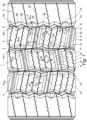
- Fig.1 shows a top view of a tread of a commercial vehicle tire.
- the tread has a central profile block row 1, two semi-central profile block rows 2 and two shoulder-side profile ribs 3.
- the central profile block row 1 is separated from each semi-central profile block row 2 by a central circumferential groove 4 and the semi-central profile block rows 2 are separated from the adjacent shoulder-side profile rib 3 by a shoulder-side circumferential groove 5.
- the circumferential grooves 4, 5 are designed in the radial direction to the respective intended profile depth, which is in particular 12.0 mm to 26.0 mm, and each have a groove base 4a (circumferential grooves 4), 5a (circumferential grooves 5).
- central profile block row 1 and each semi-central profile block row 2 is structured by a number of transverse grooves 6 which follow one another in the circumferential direction and open into the adjacent circumferential grooves 4, 5 in central profile blocks 7 (central profile block row 1) or in semi-central profile blocks 8 (semi-central profile block rows 2).
- transverse grooves 6 run, viewed in plan view and in relation to groove centre lines m QR aligned in the direction of extension, straight within each profile block row 1, 2, parallel to one another and to the axial direction at an angle ⁇ of 0° to 20°, in particular of 5° to 15°, wherein the transverse grooves 6 of the semi-central profile block rows 2 are oriented in the opposite direction to the transverse grooves 6 of the central profile block row 1 with respect to the axial direction.
- the transverse grooves 6 have a maximum depth (depth at the deepest point) of 75% to 100%, in particular up to 95%, of the tread depth in the radial direction and a
- the width b QR determined from a top view perpendicular to the groove center line m QR is from 4.0 mm to 8.0 mm.
- the transverse grooves 6 of the semi-central profile block rows 2 are offset in the circumferential direction relative to the transverse grooves 6 of the central profile block row 1. Furthermore, the transverse grooves 6 of one semi-central profile block row 2 are offset in the circumferential direction relative to the transverse grooves 6 of the other semi-central profile block row 2.
- the profile block 7, 8 has an outer block surface 9 located in the tread periphery, a block flank 10 on each adjacent transverse groove 6, two rounded transition surfaces 11 adjoining each of the block flanks 10 and a block edge 12 located in the tread periphery on each axially laterally adjacent circumferential groove 4 or 5.
- the middle profile block 7 has a block flank 13 adjoining the respective block edge 12 for each middle circumferential groove 4.
- the semi-central profile block 8 has a block flank 13 adjoining the corresponding block edge 12 for the adjacent middle circumferential groove 4 and a block flank 14 adjoining the respective block edge 12 for the adjacent shoulder-side circumferential groove 5.
- the rounded transition surfaces 11 run between the respective block flank 10 and the block outer surface 9 and, viewed in the cross-section perpendicular to the groove center line m QR in plan view, adjoin tangentially to the block flank 10 and tangentially to the block outer surface 9.
- the block flanks 10, viewed in the last-mentioned cross-section, run straight and at an angle of 0° to 5° to the radial direction.
- the transition surfaces 11 are not taken into account, so that the width b QR is determined in such a way as if the block flanks 10, viewed in the last-mentioned cross-section, continued straight to the tread periphery.
- the profile block 7, 8 is traversed by incisions 15 which lead into the respective adjacent circumferential grooves 4, 5 and which interrupt the block edges 12 in sections.
- the incisions 15 are not taken into account, so that the design of the block edges 12 is explained in such a way as if they were not interrupted by the incisions 15 and thus continued beyond the incisions 15.
- Each block edge 12 ends at the transition surfaces 11 and, viewed from above, runs in an irregular zigzag shape, with one block edge 12 running parallel to the other block edge 12 and - if the angle ⁇ of the transverse grooves 6 deviates from 0° - being offset from it in the circumferential direction.
- One block edge 12 can therefore, viewed from above, be mapped onto the other block edge 12 by parallel displacement, with the block edges 12 being offset in the circumferential direction by a K ( Fig. 2 ) to each other.
- the size of the offset a K results from the already mentioned angle ⁇ ( Fig.1 ) of the transverse grooves 6.
- Each block edge 12 has a length c K projected in the circumferential direction of 40.0 mm to 70.0 mm.
- the block edge 12 is composed, viewed in plan view, of two straight and parallel end edge sections 12a, two straight and parallel edge sections 12b following the edge sections 12a, and a straight middle edge section 12c running between the edge sections 12b, wherein the immediately successive edge sections 12a, 12b, 12c enclose angles ⁇ with one another, which can differ from one another and are each 120° to 170°, in particular 130° to 160°.
- the block edge 12 has a kink point 12d on the inside of the block and a kink point 12e on the outside of the block at the mutual connection points of the edge sections 12a, 12b, 12c. At the kink points 12d on the inside of the block, the angle ⁇ runs over the side of the respective circumferential groove 4, 5 and at the At the bends 12e on the outside of the block, the angle ⁇ runs over the outer surface 9 of the block.
- the end edge sections 12a each have a length c a projected in the circumferential direction of 12% to 22%, in particular 14% to 18%, of the length c K of the block edge 12 and, viewed in plan view, run to the circumferential direction at an angle ⁇ of 2° to 15°, in particular 5° to 10°, preferably 6° to 9°.
- the edge sections 12b each have a length c b projected in the circumferential direction of 17% to 25%, in particular 19% to 23%, of the length c K of the block edge 12 and, viewed in plan view, run in the opposite direction to the circumferential direction to the end edge sections 12a and to the circumferential direction at an angle ⁇ of 20° to 30°, in particular 23° to 27°.
- the middle edge section 12c has a length c c projected in the circumferential direction and, viewed in plan view, runs straight and at an angle ⁇ to the circumferential direction.
- the size of the length c c results from the sizes of the lengths c a , c b .
- the size of the angle ⁇ results from the lengths c a , c b , c c and the angles ⁇ , ⁇ , ⁇ .
- angles ⁇ , ⁇ , ⁇ , ⁇ and the lengths c a , c b , c c are coordinated with one another in the exemplary embodiment in such a way that the bending points 12d on the inside of the block, viewed in plan view, lie on an auxiliary line h i on the inside of the block running straight in the circumferential direction, and the bending points 12e on the outside of the block, viewed in plan view, lie on an auxiliary line h a on the outside of the block running straight in the circumferential direction.
- the block flank 14 is made up of flank sections 16 which adjoin one another in the circumferential direction and each start from an edge section 12a, 12b, 12c and which, viewed in the cross-section running perpendicular to the associated edge section 12a, 12b, 12c in plan view, run at a constant angle of 10° to 20°, in particular of 12° to 18°, to the radial direction.
- a transition rounding 17 is formed between the radially inner end of each flank section 16 of the block flank 14 and the groove base 5a.
- the block flank 13 differs from the block flank 14 in that, in addition to flank sections 16, it has a triangular, radially inner flank section 18 with a triangular base facing the groove bottom 4a, which is formed between those flank sections 15 which extend from the edge sections 12b, 12c adjoining one another at the kink point 12d on the inside of the block.
- the profile block 7, 8 is provided with the aforementioned incisions 15, which have a width of 0.4 mm to 1.8 mm, in particular of up to 1.2 mm, and a maximum depth determined in the radial direction (depth at the deepest point) of 70% to 100% of the profile depth.
- the number of incisions 15 corresponds to the number of kink points 12d, 12e of each block edge 12.
- the semi-central profile blocks 8 point to one of the adjacent central profile blocks 7 - in relation to in the axial direction auxiliary lines h B running through the centers M of the block outer surfaces 9 - have an offset a B determined in the circumferential direction of 20% to 50%, in particular of 25% to 45%, preferably of at least 40%, of that arithmetically averaged length which is determined from the lengths c K ( Fig. 2 ) of the four block edges 12 of the respective profile blocks 7, 8.
- the center point M is the intersection point of two lines which are straight in plan view and which run between the ends of the various block edges 12 of the respective profile blocks 7, 8 which are oriented opposite to one another with respect to the circumferential direction.
- the mentioned offset a B is adapted to the design of the block edges 12 as explained below.
- the block edges 12 of profile blocks 7, 8, which have the offset a B ( Fig.1 ) to one another, have axially opposite circumferential sections 12u which run along the circumferential section of the respective central circumferential groove 4 separating the profile blocks 7, 8 from one another.
- the kink(s) 12e on the outside of the block have(s) an offset a 1 of 0.5 mm to 5.0 mm, determined in the circumferential direction, to the kink(s) 12d on the inside of the block of the other block edge 12 which is closest in the circumferential direction, wherein the offset a 1 is smaller than the smallest of the lengths c a , c b , c c .
- the shoulder-side profile ribs 3 each have an outer rib surface 3a located in the tread periphery, a rib edge 3b located in the tread periphery on the adjacent shoulder-side circumferential groove 5 and a rib flank 3c adjoining this.
- the rib edge 3b runs, viewed from above, in a zigzag shape, is made up of straight edge sections 3b', which each enclose an angle ⁇ of 130° to 140° with each other, and has rib outer-side bends 3d and rib inner-side bends 3e.
- the rib edge 3b has circumferential sections 3bu, which each extend along a circumferential section of the shoulder-side circumferential groove 5 separating a semi-central profile block 8 from the shoulder-side profile rib 3 and are axially opposite the corresponding block edge 12.
- the block-outside bends 12e of the block edge 12 have an offset a 2 of 0.5 mm to 5.0 mm determined in the circumferential direction to the rib-inside bend 3e of the rib edge 3b which is closest in the circumferential direction, wherein the offset a 2 is smaller than the smallest of the lengths c a , c b , c c .
- the circumferential grooves 4, 5 have a maximum width B UR ( Fig.1 , width at the widest points) of 10.0 mm to 25.0 mm, in particular of at least 15.0 mm.
- the tread has at least one central tread block row with corresponding tread blocks, positioned anywhere.
- the central tread block row can therefore be a central tread block row running in the area of the tire equatorial plane or a central or semi-central tread block row running to the side of the tire equatorial plane.
- the shoulder-side tread ribs can be designed in a manner known per se.
- the rounded transition surfaces 11 are optional, so that the block flanks 10 connect to the block outer surface 9 and can therefore extend to the tread periphery.
Landscapes
- Engineering & Computer Science (AREA)
- Mechanical Engineering (AREA)
- Tires In General (AREA)
Abstract
Description
- Die Erfindung betrifft einen Nutzfahrzeugreifen mit einem Laufstreifen mit zumindest einer an jeder Seite von einer Umfangsrille begrenzten, mittleren Profilblockreihe mit Profilblöcken, welche durch in die Umfangsrillen einmündende Querrillen mit einer Breite von 4,0 mm bis 8,0 mm voneinander getrennt sind und an den Umfangsrillen je eine in Draufsicht zick-zack-förmig verlaufende Blockkante aufweisen, wobei sich die Blockkante aus gerade verlaufenden, miteinander jeweils einen Winkel von 120° bis 170° einschließenden Kantenabschnitten, welche endseitige Kantenabschnitte und zumindest ein zwischen diesen verlaufender, weiterer Kantenabschnitt sind, zusammensetzt und am gegenseitigen Anschluss der Kantenabschnitte eine blockinnenseitige Knickstelle oder eine blockaußenseitige Knickstelle aufweist, wobei die Profilblöcke mit in die Umfangsrillen einmündenden, parallel zueinander sowie zwischen Knickstellen der Blockkanten verlaufenden Einschnitten mit einer Breite von 0,4 mm bis 1,8 mm und einer maximalen Tiefe von 70% bis 100% versehen sind.
- Ein derartiger Nutzfahrzeugreifen ist beispielsweise aus der
US 2013/0180638 A1 bekannt. Bei einem Ausführungsbeispiel weist der Nutzfahrzeugreifen einen Laufstreifen mit einer im Bereich der Reifenäquatorialebene in Draufsicht zick-zack-förmig verlaufenden, mittleren Umfangsrille und mit zwei in Draufsicht zick-zack-förmig verlaufenden, schulterseitigen Umfangsrillen auf. Die Umfangsrillen begrenzen zwei mittlere Profilblockreihen, welche durch in die Umfangsrillen einmündende Querrillen in Profilblöcke, welche eine relativ große Umfangerstreckung aufweisen, strukturiert sind. Die Profilblöcke weisen an den Umfangsrillen in Draufsicht zick-zack-förmig verlaufende Blockkanten mit vier Kantenabschnitten auf, wobei sowohl die Einschnitte als auch die Querrillen jeweils zwischen blockinnenseitigen Knickstellen der Blockkanten verlaufen. Dieser Nutzfahrzeugreifen soll gute Traktionseigenschaften und ein gleichmäßiges Abriebverhalten aufweisen. - Bekannter Weise ist es für die Traktionseigenschaften und die Winterfahreigenschaften eines Nutzfahrzeugreifens von Vorteil, wenn sich in den mittleren Profilblöcken des Laufstreifens zwischen den Querrillen jeweils mehrere durchquerende, möglichst lange Einschnitte befinden. Bei Profilblöcken mit zick-zack-förmig verlaufenden Blockkanten sind diese Einschnitte üblicherweise ungleich lang. Vor allem die kürzeren Einschnitte neigen dabei zu Einrissen am Einschnittgrund, wobei die Ursache die am Einschnittgrund der kürzeren Einschnitte verstärkte "Stressbelastung" sein dürfte. In der Folge ist die Dauerhaltbarkeit des Reifens beeinträchtigt.
- Der Erfindung liegt daher die Aufgabe zugrunde, bei einem Nutzfahrzeugreifen der eingangs genannten Art zwischen den Querrillen mehrere Einschnitte derart anordnen zu können, dass gute Traktionseigenschaften und gute Winterfahreigenschaften sichergestellt sind, wobei die Einschnitte nicht zum Entstehen von Einrissen am Einschnittgrund neigen sollen, um die Dauerhaltbarkeit des Reifens zu verbessern.
- Gelöst wird die gestellte Aufgabe erfindungsgemäß dadurch, dass die beiden Blockkanten jeweils aus insgesamt fünf oder sieben Kantenabschnitten zusammensetzt sind, wobei die Kantenabschnitte der Blockkanten bei jedem Profilblock parallel zueinander verlaufen, wobei die endseitigen Kantenabschnitte zur Umfangsrichtung unter übereinstimmenden ersten Winkeln von 2° bis 15° und jeder weitere Kantenabschnitt zur Umfangsrichtung unter einem gegenüber dem ersten Winkel größeren Winkel verläuft und wobei die Einschnitte jeweils zwischen einer blockinnenseitigen Knickstelle der einen Blockkante und einer blockaußenseitigen Knickstelle der anderen Blockkante sowie zwischen sämtlichen Knickstellen verlaufen.
- Die Profilblöcke weisen speziell zick-zack-förmig verlaufende Blockkanten auf. Die zumindest vier Einschnitte pro Profilblock weisen infolge ihrer speziellen Anordnung zwischen den Knickstellen der zick-zack-förmig verlaufenden Blockkanten gleich große Erstreckungslängen auf, sodass die Einschnitte im Bereich ihrer Einschnittgründe eine vergleichbar gute Rissbeständigkeit aufweisen und somit die Dauerhaltbarkeit des Reifens verbessert ist. Gleichzeitig sorgen die zick-zack-förmig verlaufenden Blockkanten in Kombination mit der erhöhten Anzahl von Einschnitten pro Profilblock für gute Traktionseigenschaften und gute Winterfahreigenschaften.
- Gemäß einer bevorzugten Ausführung weist bei jedem Profilblock die eine Blockkante zur anderen Blockkante einen in Umfangsrichtung ermittelten Versatz auf. Die Einschnitte verlaufen daher zur axialen Richtung unter einem entsprechenden Winkel, wodurch, insbesondere beim Auftreten von in lateraler Richtung wirkenden Kräften, die Traktionseigenschaften weiter verbessert sind.
- Ferner ist es bevorzugt, wenn die endseitigen Kantenabschnitte der Blockkanten, welche zu in Umfangsrichtung aufeinanderfolgenden Profilblöcken gehören, in Draufsicht betrachtet, miteinander fluchten. Dies sorgt bei den an die Querrillen angrenzenden Bereichen der Profilblöcke für eine ausgewogene Steifigkeit, welche für einen gleichmäßigen Abrieb von Vorteil ist.
- Eine weitere bevorzugte Ausführung ist dadurch gekennzeichnet, dass die blockinnenseitigen Knickstellen der Blockkanten, in Draufsicht betrachtet, jeweils auf einer in Umfangsrichtung verlaufenden, ersten Hilfslinie und die blockaußenseitigen Knickstellen der Blockkanten auf einer in Umfangsrichtung verlaufenden, zur ersten Hilfslinie parallelen, zweiten Hilfslinie liegen. Dies trägt zu einer Reduktion der Stressbelastung im Bereich der Einschnittgründe bei.
- Bevorzugter Weise beträgt der Winkel, unter welchem die weiteren Kantenabschnitte, die an die endseitigen Kantenabschnitte anschließen, zur Umfangsrichtung verlaufen, 20° bis 30°, insbesondere von 23° bis 27°. Solche weiteren Kantenabschnitte verbessern die Traktionseigenschaften in Umfangsrichtung.
- Die zwei nachfolgenden, miteinander kombinierbaren, bevorzugten Ausführungen betreffen die relativen Längen der Kantenabschnitte der Blockkante und sorgen dafür, dass die durch die Einschnitte gebildeten Profilblocksegmente im Wesentlichen gleichlange Umfangslängen aufweisen, was zur einer Vergleichmäßigung der Profilsteifigkeit beiträgt und derart die Dauerhaltbarkeit des Reifens zusätzlich verbessert.
- Gemäß einer ersten diesbezüglich vorteilhaften Ausführung weisen die endseitigen Kantenabschnitte jeweils eine in Umfangsrichtung projizierte Länge von 12% bis 22%, insbesondere von 14% bis 18%, der in Umfangsrichtung projizierten Länge der Blockkante auf.
- Gemäß einer zweiten diesbezüglich vorteilhaften Ausführung weisen die weiteren Kantenabschnitte, welche an die endseitigen Kantenabschnitte anschließen, jeweils eine in die Umfangsrichtung projizierte Länge von 17% bis 25%, insbesondere von 19% bis 23%, der in Umfangsrichtung projizierten Länge der Blockkante auf.
- Eine weitere bevorzugte Ausführung ist dadurch gekennzeichnet, dass die in Umfangsrichtung projizierte Länge der Blockkante 40,0 mm bis 70,0 mm beträgt bzw. dass die Blockkante eine in die Umfangsrichtung projizierte Länge von 40,0 mm bis 70,0 mm aufweist.
- Gemäß einer weiteren bevorzugten Ausführung weisen die Profilblöcke jeweils eine in der Laufstreifenperipherie liegende Blockaußenfläche, an den angrenzenden Querrillen Blockflanken und zwischen den Blockflanken und der Blockaußenfläche verlaufende, gerundete Übergangsflächen auf, welche, im in Draufsicht senkrecht zur Rillenmittellinie der Querrille ausgerichteten Querschnitt betrachtet, tangential an die Blockflanke und tangential an die Blockaußenfläche anschließen. Die Übergangsflächen sind insbesondere für die Bremsperformance günstig.
- Bevorzugter Weise betragen die ersten Winkel, unter welchen die endseitigen Kantenabschnitte zur Umfangsrichtung verlaufen, 5° bis 10°, insbesondere 6° bis 9°.
- Eine weitere bevorzugte Ausführung ist dadurch gekennzeichnet, dass der Laufstreifen zumindest zwei, insbesondere zumindest drei, bevorzugt genau drei, einander benachbarte mittlere Profilblockreihen aufweist, wobei die Profilblöcke aus einander unmittelbar benachbarten mittleren Profilblockreihen - bezogen auf in axialer Richtung durch die Mittelpunkte der Blockaußenflächen der Profilblöcke verlaufende Hilfslinien - einen in Umfangsrichtung ermittelten Versatz von 20% bis 50%, insbesondere von 25% bis 45%, bevorzugt von zumindest 40%, einer arithmetisch gemittelten Länge aufweisen, welche aus den in Umfangsrichtung projizierten Längen der vier zu den jeweiligen Profilblöcken gehörenden Blockkanten errechnet ist. Dies trägt zu einer zusätzlichen Verbesserung der Traktionseigenschaften bei.
- Eine erste vorteilhafte Weiterbildung der zuletzt genannten bevorzugten Ausführung ist dadurch gekennzeichnet, dass bei Profilblöcken, welche den Versatz zueinander aufweisen, die Blockkanten einander axial gegenüberliegende Umfangsabschnitte aufweisen, welche entlang des die Profilblöcke voneinander trennenden Umfangsabschnitts der Umfangsrille verlaufen, wobei im Bereich des Umfangsabschnitts jeder Blockkante die blockaußenseitige(n) Knickstelle(n) zu der in Umfangsrichtung nächstliegenden, blockinnenseitigen Knickstelle der jeweils anderen Blockkante einen in Umfangsrichtung ermittelten, Versatz von 0,5 mm bis 5,0 mm aufweist bzw. aufweisen, wobei der Versatz kleiner ist die in Umfangsrichtung projizierten Längen der Kantenabschnitte der Blockkanten. Dies trägt ebenfalls zu einer zusätzlichen Verbesserung der Traktionseigenschaften bei.
- Eine zweite vorteilhafte Weiterbildung der zuletzt genannten bevorzugten Ausführung ist dadurch gekennzeichnet, dass die Profilblöcke aus einander benachbarten mittleren Profilblockreihen, in Draufsicht betrachtet, um 180° verdreht orientiert sind. Dies trägt ebenfalls zu einer Verbesserung der Traktionseigenschaften bei.
- Eine weitere bevorzugte Ausführung ist dadurch gekennzeichnet, dass zu den mittleren Profilblockreihen zumindest eine halbmittige Profilblockreihe gehört, welche zu einer schulterseitige Profilrippe benachbart ist, wobei die schulterseitige Profilrippe an der angrenzenden Umfangsrille eine in Draufsicht zick-zack-förmig verlaufende Rippenkante mit Winkel von 130° bis 140° einschließenden Kantenabschnitten aufweist, wobei an am gegenseitigen Anschluss von zwei Kantenabschnitten vorliegenden, rippenaußenseitigen Knickstelle jeweils ein Einschnitt mit einer Breite von 0,4 mm bis 1,8 mm und einer maximalen Tiefe von 70% bis 100% der Profiltiefe in die Umfangsrille einmündet. Eine derartige Kombination ist im Hinblick auf die Traktionseigenschaften besonders vorteilhaft.
- Eine weitere bevorzugte Ausführung ist dadurch gekennzeichnet, dass die Rippenkante Umfangsabschnitte aufweist, welche jeweils einer Blockkante eines halbmittigen Profilblocks der halbmittigen Profilblockreihe axial gegenüberliegen, wobei im Bereich jedes Umfangsabschnitts der Rippenkante die blockaußenseitigen Knickstellen der Blockkante zu der in Umfangsrichtung nächstliegenden, rippeninnenseitigen Knickstelle der Rippenkante einen in Umfangsrichtung ermittelten Versatz von 0,5 mm bis 5,0 mm aufweist, wobei der Versatz kleiner ist die in Umfangsrichtung projizierten Längen (der Kantenabschnitte der Blockkanten.
- Weitere Merkmale, Vorteile und Einzelheiten der Erfindung werden nun anhand der Zeichnung, die schematisch ein Ausführungsbeispiel der Erfindung darstellt, näher beschrieben. Dabei zeigen
-
Fig. 1 eine Draufsicht auf einen Laufstreifen eines Nutzfahrzeugreifens mit einer Ausführungsvariante der Erfindung und -
Fig. 2 eine vergrößerte Draufsicht im Bereich eines Profilblocks. - Gemäß der Erfindung ausgeführte Nutzfahrzeugreifen sind insbesondere Reifen für Busse oder Lastkraftwagen (LKW) sowie vorzugsweise Reifen in Radialbauart für Felgen mit einem Felgendurchmesser von 17,5, 19,5 oder 22,5 Zoll.
-
Fig. 1 zeigt eine Draufsicht auf einen Laufstreifen eines Nutzfahrzeugreifens. Der Laufstreifen weist eine zentrale Profilblockreihe 1, zwei halbmittige Profilblockreihen 2 und zwei schulterseitige Profilrippen 3 auf. Die zentrale Profilblockreihe 1 ist zu jeder halbmittigen Profilblockreihe 2 durch je eine mittlere Umfangsrille 4 und die halbmittigen Profilblockreihen 2 sind zur benachbarten, schulterseitigen Profilrippe 3 durch je eine schulterseitige Umfangsrille 5 getrennt. - Die Umfangsrillen 4, 5 sind in radialer Richtung auf die jeweils vorgesehene Profiltiefe ausgeführt, welche insbesondere 12,0 mm bis 26,0 mm beträgt, und weisen jeweils einen Rillengrund 4a (Umfangsillen 4), 5a (Umfangsrillen 5) auf.
- Die zentrale Profilblockreihe 1 und jede halbmittige Profilblockreihe 2 ist durch eine Anzahl von in Umfangsrichtung aufeinanderfolgenden, in die jeweils angrenzenden Umfangsrillen 4, 5 einmündenden Querrillen 6 in zentrale Profilblöcke 7 (zentrale Profilblockreihe 1) bzw. in halbmittige Profilblöcke 8 (halbmittige Profilblockreihen 2) strukturiert. Die Querrillen 6 verlaufen, in Draufsicht betrachtet und bezogen auf in Erstreckungsrichtung ausgerichtete Rillenmittellinien mQR, gerade, innerhalb jeder Profilblockreihe 1, 2 parallel zueinander sowie zur axialen Richtung jeweils unter einem Winkel α von 0° bis 20°, insbesondere von 5° bis 15°, wobei die Querrillen 6 der halbmittigen Profilblockreihen 2 bezüglich der axialen Richtung gegensinnig zu den Querrillen 6 der zentralen Profilblockreihe 1 orientiert sind. Die Querrillen 6 weisen in radialer Richtung eine maximale Tiefe (Tiefe an der tiefsten Stelle) von 75% bis 100%, insbesondere von bis zu 95%, der Profiltiefe und eine in Draufsicht senkrecht zur Rillenmittellinie mQR ermittelte Breite bQR von 4,0 mm bis 8,0 mm auf. Die Querrillen 6 der halbmittigen Profilblockreihen 2 sind zu den Querrillen 6 der zentralen Profilblockreihe 1 in Umfangsrichtung versetzt. Ferner sind die Querrillen 6 der einen halbmittigen Profilblockreihe 2 zu den Querrillen 6 der anderen halbmittigen Profilblockreihe 2 in Umfangsrichtung versetzt.
- Die weitere Ausgestaltung der mittleren Profilblöcke 7 und der halbmittigen Profilblöcke 8 wird nachfolgend anhand von einzelnen Profilblöcken 7, 8 erläutert.
- Der Profilblock 7, 8 weist eine in der Laufstreifenperipherie liegende Blockaußenfläche 9, an jeder angrenzenden Querrille 6 eine Blockflanke 10, zwei an je eine der Blockflanken 10 anschließende verrundete Übergangsflächen 11 und an jeder axial seitlich angrenzenden Umfangsrille 4 bzw. 5 eine in der Laufstreifenperipherie liegende Blockkante 12 auf. Der mittlere Profilblock 7 weist zu jeder mittleren Umfangsrillen 4 eine an die jeweilige Blockkante 12 anschließende Blockflanke 13 auf. Der halbmittige Profilblock 8 weist zur angrenzenden mittleren Umfangsrille 4 eine an die entsprechend Blockkante 12 anschließende Blockflanke 13 und zur angrenzenden schulterseitigen Umfangsrille 5 eine an die jeweilige Bockkante 12 anschließende Blockflanke 14 auf.
- Die verrundeten Übergangsflächen 11 verlaufen zwischen der jeweiligen Blockflanke 10 und der Blockaußenfläche 9 und schließen, im in Draufsicht senkrecht zur Rillenmittellinie mQR verlaufenden Querschnitt betrachtet, tangential an die Blockflanke 10 und tangential an die Blockaußenfläche 9 an. Die Blockflanken 10 verlaufen, im zuletzt erwähnten Querschnitt betrachtet, gerade sowie zur radialen Richtung unter einem Winkel von 0° bis 5°. Bei der Ermittlung der erwähnten Breite bQR der Querrillen 6 bleiben die Übergangsflächen 11 unberücksichtigt, sodass die Ermittlung der Breite bQR derart erfolgt, als wären die Blockflanken 10, im zuletzt erwähnten Querschnitt betrachtet, gerade bis zur Laufstreifenperipherie fortgeführt.
- Wie noch genauer erläutert wird, ist der Profilblock 7, 8 von in die jeweils angrenzenden Umfangsrillen 4, 5 einmündenden Einschnitten 15 durchquert, welche die Blockkanten 12 abschnittsweise unterbrechen. Bei den nachfolgenden Erläuterungen zu den Blockkanten 12 bleiben die Einschnitte 15 unberücksichtigt, sodass die Ausgestaltung der Blockkanten 12 derart erläutert ist, als wären diese durch die Einschnitte 15 nicht unterbrochen und somit über die Einschnitte 15 hinweg fortgeführt.
- Jede Blockkante 12 endet an den Übergangsflächen 11 und verläuft, in Draufsicht betrachtet, unregelmäßig zick-zack-förmig, wobei die eine Blockkante 12 parallel zur anderen Blockkante 12 verläuft und - sofern der Winkel α der Querrillen 6 von 0° abweicht- zur dieser in Umfangsrichtung versetzt ist. Die eine Blockkante 12 ist daher, in Draufsicht betrachtet, durch Parallelverschieben auf die andere Blockkante 12 abbildbar, wobei die Blockkanten 12 unter einem in Umfangsrichtung ermittelten Versatz aK (
Fig. 2 ) zueinander verlaufen. Die Größe des Versatzes aK resultiert aus den bereits erwähnten Winkel α (Fig. 1 ) der Querrillen 6. - Gemäß
Fig. 2 weist jede Blockkante 12 eine in die Umfangsrichtung projizierte Länge cK von 40,0 mm bis 70,0 mm auf. Die Blockkante 12 setzt sich, in Draufsicht betrachtet, aus zwei gerade und parallel zueinander verlaufenden, endseitigen Kantenabschnitten 12a, zwei auf die Kantenabschnitte 12a folgende, gerade und parallel zueinander verlaufende Kantenabschnitte 12b und einem gerade sowie zwischen den Kantenabschnitten 12b verlaufenden, mittleren Kantenabschnitt 12c zusammen, wobei die unmittelbar aufeinanderfolgenden Kantenabschnitte 12a, 12b, 12c miteinander Winkel β einschließen, welche voneinander abweichen können und jeweils 120° bis 170°, insbesondere von 130° bis 160°, betragen. Die Blockkante 12 weist an den gegenseitigen Anschlussstellen der Kantenabschnitte 12a, 12b, 12c eine blockinnenseitige Knickstelle 12d bzw. eine blockaußenseitige Knickstelle 12e auf. Bei den blockinnenseitigen Knickstellen 12d verläuft der Winkel β über die Seite der jeweilige Umfangsrille 4, 5 und an den blockaußenseitigen Knickstellen 12e verläuft der Winkel β über die Blockaußenfläche 9. - Die endseitigen Kantenabschnitte 12a weisen jeweils eine in Umfangsrichtung projizierte Länge ca von 12% bis 22%, insbesondere von 14% bis 18%, der Länge cK der Blockkante 12 auf und verlaufen, in Draufsicht betrachtet, zur Umfangsrichtung jeweils unter einem Winkel γ von 2° bis 15°, insbesondere von 5° bis 10°, bevorzugt von 6° bis 9°. Die Kantenabschnitte 12b weisen jeweils eine in die Umfangsrichtung projizierte Länge cb von 17% bis 25%, insbesondere von 19% bis 23%,der Länge cK der Blockkante 12 auf und verlaufen, in Draufsicht betrachtet, zur Umfangsrichtung gegensinnig geneigt zu den endseitigen Kantenabschnitten 12a sowie zur Umfangsrichtung unter einem Winkel δ von 20° bis 30°, insbesondere von 23° bis 27°. Der mittlere Kantenabschnitt 12c weist eine in die Umfangsrichtung projizierte Länge cc auf und verläuft, in Draufsicht betrachtet, gerade sowie zur Umfangsrichtung unter einem Winkel ε. Die Größe der Länge cc ergibt sich aus den Größen der Längen ca, cb. Die Größe des Winkels ε ergibt sich aus den Längen ca, cb, cc und den Winkel β, γ, δ.
- Die Winkel β, γ, δ, ε sowie die Längen ca, cb, cc sind beim Ausführungsbeispiel derart aufeinander abgestimmt, dass die blockinnenseitigen Knickstellen 12d, in Draufsicht betrachtet, auf einer gerade in Umfangsrichtung verlaufenden, blockinnenseitigen Hilfslinie hi und die blockaußenseitigen Knickstellen 12e, in Draufsicht betrachtet, auf einer gerade in Umfangsrichtung verlaufenden, blockaußenseitigen Hilfslinie ha liegen.
- Die Blockflanke 14 setzt sich aus in Umfangsrichtung aneinander anschließenden, von je einem Kantenabschnitt 12a, 12b, 12c ausgehenden, Flankenabschnitten 16 zusammen, welche, im in Draufsicht senkrecht zum zugehörigen Kantenabschnitt 12a, 12b, 12c verlaufenden Querschnitt betrachtet, zur radialen Richtung unter einem konstanten Winkel von 10° bis 20°, insbesondere von 12° bis 18°, verlaufen. Zwischen dem radial inneren Ende jedes Flankenabschnitts 16 der Blockflanke 14 und dem Rillengrund 5a ist jeweils eine Übergangsrundung 17 ausgebildet.
- Die Blockflanke 13 unterscheidet sich von der Blockflanke 14 dadurch, dass sie neben Flankenabschnitten 16 einen dreieckförmigen, radial innerer Flankenabschnitt 18 mit einer dem Rillengrund 4a zugewandten Dreieckbasis aufweist, welcher zwischen jenen Flankenabschnitten 15 ausgebildet ist, die von den an der blockinnenseitigen Knickstelle 12d aneinander anschließenden Kantenabschnitten 12b, 12c ausgehen.
- Gemäß
Fig. 1 ist der Profilblock 7, 8 mit den bereits erwähnten Einschnitten 15, welche eine Breite von 0,4 mm bis 1,8 mm, insbesondere von bis zu 1,2 mm, und eine in radialer Richtung ermittelte maximale Tiefe (Tiefe an der tiefsten Stelle) von 70% bis 100% der Profiltiefe aufweisen, versehen. Die Einschnitte 15 durchquerenden den Profilblock 7, 8, verlaufen, in Draufsicht betrachtet und bezogen auf in Erstreckungsrichtung ausgerichtete Einschnittmittellinien mE, parallel zueinander, insbesondere gerade, sowie - wieFig. 2 zeigt - jeweils zwischen der blockinnenseitigen Knickstelle 12d der einen Blockkante 12 und der zu dieser blockinnenseitigen Knickstelle 12d den Versatz aK aufweisenden, blockaußenseitigen Knickstelle 12e der jeweils anderen Blockkante 12. Die Anzahl der Einschnitte 15 stimmt mit der Anzahl der Knickstellen 12d, 12e jeder Blockkante 12 überein. - Wie
Fig. 1 ferner zeigt, ist die Ausgestaltung der Profilblöcke 7, 8 innerhalb der jeweiligen Profilblockreihe 1, 2 ferner derart, dass die endseitigen Kantenabschnitte 12a der Blockkanten 12, welche zu in Umfangsrichtung aufeinanderfolgenden Profilblöcken 7 bzw. 8 gehören, in Draufsicht betrachtet, miteinander fluchtend, also in geradliniger Verlängerung zueinander, verlaufen. Darüber hinaus sind die halbmittigen Profilblöcke 8 zu den zentralen Profilböcken 7, in Draufsicht betrachtet, um 180° verdreht orientiert. Außerdem sind die halbmittigen Profilblöcke 8 zu den zentralen Profilblöcken 7 - entsprechend dem bereits erwähnten Versatz zwischen den Querrillen 6 - ebenfalls in Umfangsrichtung zueinander versetzt. Die halbmittigen Profilblöcke 8 weisen zu einem der benachbarten zentralen Profilblöcke 7 - bezogen auf in axialer Richtung durch die Mittelpunkte M der Blockaußenflächen 9 verlaufende Hilfslinien hB - einen in Umfangsrichtung ermittelten Versatz aB von 20% bis 50%, insbesondere von 25% bis 45%, bevorzugt von zumindest 40%, jener arithmetisch gemittelten Länge auf, welche aus den Längen cK (Fig. 2 ) der vier Blockkanten 12 der jeweiligen Profilblöcke 7, 8 errechnet ist. Der Mittelpunkt M ist der Schnittpunkt von zwei in Draufsicht gerade verlaufenen Linien, welche zwischen den bezüglich der Umfangsrichtung entgegengesetzt zueinander orientierten Enden der verschiedenen Blockkanten 12 des jeweiligen Profilblocks 7, 8 verlaufen. - Bevorzugter Weise ist der erwähnte Versatz aB auf die Ausführung der Blockkanten 12 wie nachfolgend erläutert abgestimmt. Gemäß
Fig. 2 weisen die Blockkanten 12 von Profilblöcken 7, 8, welche den Versatz aB (Fig. 1 ) zueinander aufweisen, einander axial gegenüberliegende Umfangsabschnitte 12u auf, welche entlang des die Profilblöcke 7, 8 voneinander trennenden Umfangsabschnitts der jeweiligen mittleren Umfangsrille 4 verlaufen. Im Bereich des Umfangsabschnitts 12u jeder Blockkante 12 weist bzw. weisen die blockaußenseitige(n) Knickstelle(n) 12e zu der in Umfangsrichtung nächstliegenden, blockinnenseitigen Knickstelle 12d der jeweils anderen Blockkante 12 einen in Umfangsrichtung ermittelten Versatz a1 von 0,5 mm bis 5,0 mm auf, wobei der Versatz a1 kleiner ist als die kleinste der Längen ca, cb, cc. - Wie
Fig. 1 zeigt, weisen die schulterseitigen Profilrippen 3 jeweils eine in der Laufstreifenperipherie liegende Rippenaußenfläche 3a, an der angrenzenden schulterseitigen Umfangsrille 5 eine in der Laufstreifenperipherie liegende Rippenkante 3b und eine an diese anschließende Rippenflanke 3c auf. Die Rippenkante 3b verläuft, in Draufsicht betrachtet, zick-zack-förmig, setzt sich aus gerade verlaufenden Kantenabschnitten 3b' zusammen, welche miteinander jeweils einen Winkel η von 130° bis 140° einschließen, und weist rippenaußenseitige Knickstellen 3d und rippeninnenseitige Knickstellen 3e auf. Die schulterseitigen Profilrippen 3 sind jeweils mit Einschnitten 19 mit eine Breite von 0,4 mm bis 1,8 mm, insbesondere von bis zu 1,2 mm, und einer in radialer Richtung ermittelten maximalen Tiefe (Tiefe an der tiefsten Stelle) von 70% bis 100% der Profiltiefe versehen, wobei die Einschnitte 19 jeweils an einer rippenaußenseitigen Knickstelle 3d in die jeweilige schulterseitige Umfangsrille 5 einmünden. Die Anzahl der Einschnitte 19 stimmt mit der Anzahl der rippenaußenseitigen Knickstellen 3d überein. - Gemäß
Fig. 2 weist die Rippenkante 3b Umfangsabschnitte 3bu auf, welche sich jeweils entlang eines einen halbmittigen Profilblock 8 von der schulterseitigen Profilrippe 3 trennenden Umfangsabschnitts der schulterseitigen Umfangsrille 5 erstrecken und der entsprechenden Blockkante 12 axial gegenüberliegen. Im Bereich des Umfangsabschnitts 3bu weisen die blockaußenseitigen Knickstellen 12e der Blockkante 12 zu der in Umfangsrichtung nächstliegenden, rippeninnenseitigen Knickstelle 3e der Rippenkante 3b einen in Umfangsrichtung ermittelten Versatz a2 von 0,5 mm bis 5,0 mm auf, wobei der Versatz a2 kleiner ist als die kleinste der Längen ca, cb, cc. - Die Umfangsrillen 4, 5 weisen an der Laufstreifenperipherie eine in axialer Richtung ermittelte maximale Breite BUR (
Fig. 1 , Breite an den breitesten Stellen) von 10,0 mm bis 25,0 mm, insbesondere von zumindest 15,0 mm, auf. - Die Erfindung ist auf das beschriebene Ausführungsbeispiel nicht beschränkt.
- Der Laufstreifen weist zumindest eine beliebig positionierte mittlere Profilblockreihe mit entsprechenden Profilblöcken auf. Die mittlere Profilblockreihe kann daher eine im Bereich der Reifenäquatorialebene verlaufende zentrale Profilblockreihe oder eine seitlich der Reifenäquatorialebene verlaufende mittige bzw. halbmittige Profilblockreihe sein. Die schulterseitigen Profilrippen können in an sich bekannter Weise ausgeführt sein. Die verrundeten Übergangsflächen 11 sind optional, sodass die Blockflanken 10 an die Blockaußenfläche 9 anschließen und daher bis zur Laufstreifenperipherie reichen können.
-
- 1
- zentrale Profilblockreihe
- 2
- halbmittige Profilblockreihe
- 3
- schulterseitige Profilrippe
- 3a
- Rippenaußenfläche
- 3b
- Rippenkante
- 3bU
- Umfangsabschnitt
- 3b
- Kantenabschnitt
- 3c
- Rippenflanke
- 3d
- rippenaußenseitige Knickstelle
- 3e
- rippeninnenseitige Knickstelle
- 4
- mittlere Umfangsrille
- 4a
- Rillengrund
- 5
- schulterseitige Umfangsrille
- 5a
- Rillengrund
- 6
- Querrille
- 7
- zentraler Profilblock
- 8
- halbmittiger Profilblock
- 9
- Blockaußenfläche
- 10
- Blockflanke
- 11
- Übergangsfläche
- 12
- Blockkante
- 12a
- endseitiger Kantenabschnitt
- 12b
- Kantenabschnitt
- 12c
- mittlerer Kantenabschnitt
- 12d
- blockinnenseitige Knickstelle
- 12e
- blockaußenseitige Knickstelle
- 12u
- Umfangsabschnitt
- 13
- Blockflanke
- 14
- Blockflanke
- 15
- Einschnitt
- 16
- Flankenabschnitt
- 17
- Übergangsrundung
- 18
- radial innerer Flankenabschnitt
- 19
- Einschnitt
- a1, a2, aB, aK
- Versatz
- bQR
- Breite
- BUR
- maximale Breite
- ca, cb, cc, cK
- Länge
- ha
- blockaußenseitige Hilfslinie
- hb
- Hilfslinie
- hi
- blockinnenseitige Hilfslinie
- M
- MittelpunktmE
- Einschnittmittellinie
- mQR
- Rillenmittellinie α, β, γ, δ, ε, η
- Winkel
Claims (15)
- Nutzfahrzeugreifen mit einem Laufstreifen mit zumindest einer an jeder Seite von einer Umfangsrille (4, 5) begrenzten, mittleren Profilblockreihe (1, 2) mit Profilblöcken (7, 8), welche durch in die Umfangsrillen (4, 5) einmündende Querrillen (6) mit einer Breite (bQR) von 4,0 mm bis 8,0 mm voneinander getrennt sind und an den Umfangsrillen (4, 5) je eine in Draufsicht zick-zack-förmig verlaufende Blockkante (12) aufweisen, wobei sich die Blockkante (12) aus gerade verlaufenden, miteinander jeweils einen Winkel (β) von 120° bis 170° einschließenden Kantenabschnitten (12a, 12b, 12c), welche endseitige Kantenabschnitte (12a) und zumindest ein zwischen diesen verlaufender, weiterer Kantenabschnitt (12b, 12c) sind, zusammensetzt und am gegenseitigen Anschluss der Kantenabschnitte (12b, 12c) eine blockinnenseitige Knickstelle (12d) oder eine blockaußenseitige Knickstelle (12e) aufweist, wobei die Profilblöcke (7, 8) mit in die Umfangsrillen (4, 5) einmündenden, parallel zueinander sowie zwischen Knickstellen (12d, 12e) der Blockkanten (12) verlaufenden Einschnitten (15) mit einer Breite von 0,4 mm bis 1,8 mm und einer maximalen Tiefe von 70% bis 100% versehen sind,
dadurch gekenzeichnet,
dass die beiden Blockkanten (12) jeweils aus insgesamt fünf oder sieben Kantenabschnitten (12a, 12b, 12c) zusammensetzt sind, wobei die Kantenabschnitte (12a, 12b, 12c) der Blockkanten (12) bei jedem Profilblock (7, 8) parallel zueinander verlaufen, wobei die endseitigen Kantenabschnitte (12a) zur Umfangsrichtung unter übereinstimmenden ersten Winkeln (γ) von 2° bis 15° und jeder weitere Kantenabschnitt (12b, 12c) zur Umfangsrichtung unter einem gegenüber dem ersten Winkel (γ) größeren Winkel (δ, ε) verläuft und wobei die Einschnitte (15) jeweils zwischen einer blockinnenseitigen Knickstelle (12d) der einen Blockkante (12) und einer blockaußenseitigen Knickstelle (12e) der anderen Blockkante (12) sowie zwischen sämtlichen Knickstellen (12e, 12d) verlaufen. - Nutzfahrzeugreifen nach Anspruch 1, dadurch gekennzeichnet, dass bei jedem Profilblock (7, 8) die eine Blockkante (12) zur anderen Blockkante (12) einen in Umfangsrichtung ermittelten Versatz (aK) aufweist.
- Nutzfahrzeugreifen nach Anspruch 1 oder 2, dadurch gekennzeichnet, dass die endseitigen Kantenabschnitte (12a) der Blockkanten (12), welche zu in Umfangsrichtung aufeinanderfolgenden Profilblöcken (7, 8) gehören, in Draufsicht betrachtet, miteinander fluchten.
- Nutzfahrzeugreifen nach einem der Ansprüche 1 bis 3, dadurch gekennzeichnet, dass die blockinnenseitigen Knickstellen (12d) der Blockkanten (12), in Draufsicht betrachtet, jeweils auf einer in Umfangsrichtung verlaufenden, ersten Hilfslinie (hi) und die blockaußenseitigen Knickstellen (12e) der Blockkanten (12) auf einer in Umfangsrichtung verlaufenden, zur ersten Hilfslinie (hi) parallelen, zweiten Hilfslinie (ha) liegen.
- Nutzfahrzeugreifen nach einem der Ansprüche 1 bis 4, dadurch gekennzeichnet, dass der Winkel (δ), unter welchem die weiteren Kantenabschnitte (12b), die an die endseitigen Kantenabschnitte (12a) anschließen, zur Umfangsrichtung verlaufen, 20° bis 30°, insbesondere von 23° bis 27°, beträgt.
- Nutzfahrzeugreifen nach einem der Ansprüche 1 bis 5, dadurch gekennzeichnet, dass die endseitigen Kantenabschnitte (12a) jeweils eine in Umfangsrichtung projizierte Länge (ca) von 12% bis 22%, insbesondere von 14% bis 18%, der in Umfangsrichtung projizierten Länge (cK) der Blockkante (12) aufweisen.
- Nutzfahrzeugreifen nach einem der Ansprüche 1 bis 6, dadurch gekennzeichnet, dass die weiteren Kantenabschnitte (12b), welche an die endseitigen Kantenabschnitte (12a) anschließen, jeweils eine in die Umfangsrichtung projizierte Länge (cb) von 17% bis 25%, insbesondere von 19% bis 23%, der in Umfangsrichtung projizierten Länge (cK) der Blockkante (12) aufweisen.
- Nutzfahrzeugreifen nach einem der Ansprüche 1 bis 7, dadurch gekennzeichnet, dass die in Umfangsrichtung projizierte Länge (cK) der Blockkante (12) 40,0 mm bis 70,0 mm beträgt bzw.
dass die Blockkante (12) eine in die Umfangsrichtung projizierte Länge (cK) von 40,0 mm bis 70,0 mm aufweist. - Nutzfahrzeugreifen nach einem der Ansprüche 1 bis 8, dadurch gekennzeichnet, dass die Profilblöcke (7, 8) jeweils eine in der Laufstreifenperipherie liegende Blockaußenfläche (9), an den angrenzenden Querrillen (6) Blockflanken (10) und zwischen den Blockflanken (10) und der Blockaußenfläche (9) verlaufende, gerundete Übergangsflächen (11) aufweisen, welche, im in Draufsicht senkrecht zur Rillenmittellinie (mQR) der Querrille (6) ausgerichteten Querschnitt betrachtet, tangential an die Blockflanke (10) und tangential an die Blockaußenfläche (9) anschließen.
- Nutzfahrzeugreifen nach einem der Ansprüche 1 bis 9, dadurch gekennzeichnet, dass die ersten Winkel (γ), unter welchen die endseitigen Kantenabschnitte (12a) zur Umfangsrichtung verlaufen, 5° bis 10°, insbesondere 6° bis 9°, betragen.
- Nutzfahrzeugreifen nach einem der Ansprüche 1 bis 10, dadurch gekennzeichnet, dass der Laufstreifen zumindest zwei, insbesondere zumindest drei, bevorzugt genau drei, einander benachbarte mittlere Profilblockreihen (1, 2) aufweist, wobei die Profilblöcke (7, 8) aus einander unmittelbar benachbarten mittleren Profilblockreihen (1, 2) - bezogen auf in axialer Richtung durch die Mittelpunkte (M) der Blockaußenflächen (9) der Profilblöcke (7, 8) verlaufende Hilfslinien (hB) - einen in Umfangsrichtung ermittelten Versatz (aB) von 20% bis 50%, insbesondere von 25% bis 45%, bevorzugt von zumindest 40%, einer arithmetisch gemittelten Länge aufweisen, welche aus den in Umfangsrichtung projizierten Längen (cK) der vier zu den jeweiligen Profilblöcken (7, 8) gehörenden Blockkanten (12) errechnet ist.
- Nutzfahrzeugreifen nach Anspruch 11, dadurch gekennzeichnet, dass bei Profilblöcken (7, 8), welche den Versatz (aB) zueinander aufweisen, die Blockkanten (12) einander axial gegenüberliegende Umfangsabschnitte (12u) aufweisen, welche entlang des die Profilblöcke (7, 8) voneinander trennenden Umfangsabschnitts der Umfangsrille (4) verlaufen, wobei im Bereich des Umfangsabschnitts (12u) jeder Blockkante (12) die blockaußenseitige(n) Knickstelle(n) (12e) zu der in Umfangsrichtung nächstliegenden, blockinnenseitigen Knickstelle (12d) der jeweils anderen Blockkante (12) einen in Umfangsrichtung ermittelten Versatz (a1) von 0,5 mm bis 5,0 mm aufweist bzw. aufweisen, wobei der Versatz (a1) kleiner ist die in Umfangsrichtung projizierten Längen (ca, cb, cc) der Kantenabschnitte (12a, 12b, 12c) der Blockkanten (12).
- Nutzfahrzeugreifen nach Anspruch 11 oder 12, dadurch gekennzeichnet, dass die Profilblöcke (7, 8) aus einander benachbarten mittleren Profilblockreihen (1, 2), in Draufsicht betrachtet, um 180° verdreht orientiert sind.
- Nutzfahrzeugreifen nach einem der Ansprüche 1 bis 13, dadurch gekennzeichnet, dass zu den mittleren Profilblockreihen (1, 2) zumindest eine halbmittige Profilblockreihe (2) gehört, welche zu einer schulterseitige Profilrippe (3) benachbart ist, wobei die schulterseitige Profilrippe (3) an der angrenzenden Umfangsrille (5) eine in Draufsicht zick-zack-förmig verlaufende Rippenkante (3b) mit Winkel (η) von 130° bis 140° einschließenden Kantenabschnitten (3b`) aufweist, wobei an am gegenseitigen Anschluss von zwei Kantenabschnitten (3b`) vorliegenden, rippenaußenseitigen Knickstelle (3d) jeweils ein Einschnitt (20) mit einer Breite von 0,4 mm bis 1,8 mm und einer maximalen Tiefe von 70% bis 100% der Profiltiefe in die Umfangsrille (5) einmündet.
- Nutzfahrzeugreifen nach Anspruch 14, dadurch gekennzeichnet, dass die Rippenkante (3b) Umfangsabschnitte (3u) aufweist, welche jeweils einer Blockkante (12) eines halbmittigen Profilblocks (8) der halbmittigen Profilblockreihe (2) axial gegenüberliegen, wobei im Bereich jedes Umfangsabschnitts (3bu) der Rippenkante (3b) die blockaußenseitigen Knickstellen (12e) der Blockkante (12) zu der in Umfangsrichtung nächstliegenden, rippeninnenseitigen Knickstelle (3e) der Rippenkante (3b) einen in Umfangsrichtung ermittelten Versatz (a2) von 0,5 mm bis 5,0 mm aufweist, wobei der Versatz (a2) kleiner ist die in Umfangsrichtung projizierten Längen (ca, cb, cc) der Kantenabschnitte (12a, 12b, 12c) der Blockkanten (12).
Applications Claiming Priority (1)
| Application Number | Priority Date | Filing Date | Title |
|---|---|---|---|
| DE102023202475.6A DE102023202475A1 (de) | 2023-03-21 | 2023-03-21 | Nutzfahrzeugreifen |
Publications (2)
| Publication Number | Publication Date |
|---|---|
| EP4434769A1 true EP4434769A1 (de) | 2024-09-25 |
| EP4434769B1 EP4434769B1 (de) | 2025-12-17 |
Family
ID=90038368
Family Applications (1)
| Application Number | Title | Priority Date | Filing Date |
|---|---|---|---|
| EP24158817.7A Active EP4434769B1 (de) | 2023-03-21 | 2024-02-21 | Nutzfahrzeugreifen |
Country Status (2)
| Country | Link |
|---|---|
| EP (1) | EP4434769B1 (de) |
| DE (1) | DE102023202475A1 (de) |
Citations (11)
| Publication number | Priority date | Publication date | Assignee | Title |
|---|---|---|---|---|
| US4230512A (en) * | 1978-04-08 | 1980-10-28 | Bridgestone Tire Co., Ltd. | Center block side rib tread pattern for heavy vehicle radial tires |
| US4345632A (en) * | 1979-11-29 | 1982-08-24 | Bridgestone Tire Co., Ltd. | Tread with spaced projections in stone ejecting groove |
| JPS63291705A (ja) * | 1987-05-22 | 1988-11-29 | Bridgestone Corp | 重荷重用空気入りラジアルタイヤ |
| EP0333397A2 (de) * | 1988-03-14 | 1989-09-20 | Sumitomo Rubber Industries Limited | Radialer Luftreifen |
| JPH08192607A (ja) * | 1994-11-17 | 1996-07-30 | Bridgestone Corp | 重荷重用空気入りタイヤ |
| CN101524950A (zh) * | 2008-03-07 | 2009-09-09 | 锦湖轮胎株式会社 | 重载用充气子午线轮胎 |
| US20110108176A1 (en) * | 2008-07-10 | 2011-05-12 | Bridgestone Corporation | Tire |
| US20130180638A1 (en) | 2012-01-16 | 2013-07-18 | Sumitomo Rubber Industries, Ltd. | Heavy duty pneumatic tire |
| JP2013147171A (ja) * | 2012-01-20 | 2013-08-01 | Bridgestone Corp | タイヤ |
| CN103350617A (zh) * | 2013-07-25 | 2013-10-16 | 厦门正新橡胶工业有限公司 | 子午线轮胎胎面结构 |
| US20180339557A1 (en) * | 2017-05-29 | 2018-11-29 | Sumitomo Rubber Industries, Ltd. | Tire |
-
2023
- 2023-03-21 DE DE102023202475.6A patent/DE102023202475A1/de active Pending
-
2024
- 2024-02-21 EP EP24158817.7A patent/EP4434769B1/de active Active
Patent Citations (11)
| Publication number | Priority date | Publication date | Assignee | Title |
|---|---|---|---|---|
| US4230512A (en) * | 1978-04-08 | 1980-10-28 | Bridgestone Tire Co., Ltd. | Center block side rib tread pattern for heavy vehicle radial tires |
| US4345632A (en) * | 1979-11-29 | 1982-08-24 | Bridgestone Tire Co., Ltd. | Tread with spaced projections in stone ejecting groove |
| JPS63291705A (ja) * | 1987-05-22 | 1988-11-29 | Bridgestone Corp | 重荷重用空気入りラジアルタイヤ |
| EP0333397A2 (de) * | 1988-03-14 | 1989-09-20 | Sumitomo Rubber Industries Limited | Radialer Luftreifen |
| JPH08192607A (ja) * | 1994-11-17 | 1996-07-30 | Bridgestone Corp | 重荷重用空気入りタイヤ |
| CN101524950A (zh) * | 2008-03-07 | 2009-09-09 | 锦湖轮胎株式会社 | 重载用充气子午线轮胎 |
| US20110108176A1 (en) * | 2008-07-10 | 2011-05-12 | Bridgestone Corporation | Tire |
| US20130180638A1 (en) | 2012-01-16 | 2013-07-18 | Sumitomo Rubber Industries, Ltd. | Heavy duty pneumatic tire |
| JP2013147171A (ja) * | 2012-01-20 | 2013-08-01 | Bridgestone Corp | タイヤ |
| CN103350617A (zh) * | 2013-07-25 | 2013-10-16 | 厦门正新橡胶工业有限公司 | 子午线轮胎胎面结构 |
| US20180339557A1 (en) * | 2017-05-29 | 2018-11-29 | Sumitomo Rubber Industries, Ltd. | Tire |
Also Published As
| Publication number | Publication date |
|---|---|
| DE102023202475A1 (de) | 2024-09-26 |
| EP4434769B1 (de) | 2025-12-17 |
Similar Documents
| Publication | Publication Date | Title |
|---|---|---|
| EP3888948B1 (de) | Fahrzeugluftreifen, insbesondere nutzfahrzeugreifen | |
| EP2070731A1 (de) | Fahrzeugluftreifen | |
| DE102018208349A1 (de) | Fahrzeugluftreifen | |
| DE102020212456A1 (de) | Fahrzeugluftreifen | |
| EP3805019B1 (de) | Fahrzeugluftreifen | |
| EP2785537A1 (de) | Fahrzeugluftreifen | |
| EP2138328B1 (de) | Fahrzeugluftreifen | |
| EP4434769A1 (de) | Nutzfahrzeugreifen | |
| EP3978274B1 (de) | Nutzfahrzeugreifen | |
| EP4347276B1 (de) | Fahrzeugluftreifen | |
| DE102023202718A1 (de) | Fahrzeugluftreifen | |
| EP4474173B1 (de) | Fahrzeugluftreifen | |
| EP3825151B1 (de) | Fahrzeugluftreifen mit einem laufstreifen | |
| EP3715148B1 (de) | Fahrzeugluftreifen | |
| EP4147885B1 (de) | Fahrzeugreifen | |
| EP4385761B1 (de) | Fahrzeugluftreifen | |
| EP4551413B1 (de) | Fahrzeugluftreifen | |
| EP4434768B1 (de) | Fahrzeugluftreifen | |
| EP4624201A1 (de) | Fahrzeugreifen | |
| DE102024108084A1 (de) | Fahrzeugreifen | |
| DE102023213207A1 (de) | Fahrzeugreifen, insbesondere Nutzfahrzeugreifen | |
| DE102024207453A1 (de) | Fahrzeugreifen | |
| EP4667240A1 (de) | Fahrzeugreifen | |
| DE102023206854A1 (de) | Fahrzeugreifen | |
| EP3415344B1 (de) | Fahrzeugluftreifen |
Legal Events
| Date | Code | Title | Description |
|---|---|---|---|
| PUAI | Public reference made under article 153(3) epc to a published international application that has entered the european phase |
Free format text: ORIGINAL CODE: 0009012 |
|
| STAA | Information on the status of an ep patent application or granted ep patent |
Free format text: STATUS: THE APPLICATION HAS BEEN PUBLISHED |
|
| AK | Designated contracting states |
Kind code of ref document: A1 Designated state(s): AL AT BE BG CH CY CZ DE DK EE ES FI FR GB GR HR HU IE IS IT LI LT LU LV MC ME MK MT NL NO PL PT RO RS SE SI SK SM TR |
|
| STAA | Information on the status of an ep patent application or granted ep patent |
Free format text: STATUS: REQUEST FOR EXAMINATION WAS MADE |
|
| 17P | Request for examination filed |
Effective date: 20250325 |
|
| RIC1 | Information provided on ipc code assigned before grant |
Ipc: B60C 11/03 20060101AFI20250724BHEP Ipc: B60C 11/12 20060101ALI20250724BHEP |
|
| GRAP | Despatch of communication of intention to grant a patent |
Free format text: ORIGINAL CODE: EPIDOSNIGR1 |
|
| STAA | Information on the status of an ep patent application or granted ep patent |
Free format text: STATUS: GRANT OF PATENT IS INTENDED |
|
| INTG | Intention to grant announced |
Effective date: 20250910 |
|
| GRAS | Grant fee paid |
Free format text: ORIGINAL CODE: EPIDOSNIGR3 |
|
| GRAA | (expected) grant |
Free format text: ORIGINAL CODE: 0009210 |
|
| STAA | Information on the status of an ep patent application or granted ep patent |
Free format text: STATUS: THE PATENT HAS BEEN GRANTED |
|
| AK | Designated contracting states |
Kind code of ref document: B1 Designated state(s): AL AT BE BG CH CY CZ DE DK EE ES FI FR GB GR HR HU IE IS IT LI LT LU LV MC ME MK MT NL NO PL PT RO RS SE SI SK SM TR |
|
| REG | Reference to a national code |
Ref country code: CH Ref legal event code: F10 Free format text: ST27 STATUS EVENT CODE: U-0-0-F10-F00 (AS PROVIDED BY THE NATIONAL OFFICE) Effective date: 20251217 Ref country code: GB Ref legal event code: FG4D Free format text: NOT ENGLISH |
|
| REG | Reference to a national code |
Ref country code: DE Ref legal event code: R096 Ref document number: 502024000503 Country of ref document: DE |
|
| PGFP | Annual fee paid to national office [announced via postgrant information from national office to epo] |
Ref country code: SE Payment date: 20260218 Year of fee payment: 3 |
|
| REG | Reference to a national code |
Ref country code: LT Ref legal event code: MG9D |
|
| PG25 | Lapsed in a contracting state [announced via postgrant information from national office to epo] |
Ref country code: NO Free format text: LAPSE BECAUSE OF FAILURE TO SUBMIT A TRANSLATION OF THE DESCRIPTION OR TO PAY THE FEE WITHIN THE PRESCRIBED TIME-LIMIT Effective date: 20260317 |
|
| PGFP | Annual fee paid to national office [announced via postgrant information from national office to epo] |
Ref country code: DE Payment date: 20260228 Year of fee payment: 3 |
|
| PG25 | Lapsed in a contracting state [announced via postgrant information from national office to epo] |
Ref country code: FI Free format text: LAPSE BECAUSE OF FAILURE TO SUBMIT A TRANSLATION OF THE DESCRIPTION OR TO PAY THE FEE WITHIN THE PRESCRIBED TIME-LIMIT Effective date: 20251217 Ref country code: HR Free format text: LAPSE BECAUSE OF FAILURE TO SUBMIT A TRANSLATION OF THE DESCRIPTION OR TO PAY THE FEE WITHIN THE PRESCRIBED TIME-LIMIT Effective date: 20251217 |
|
| PGFP | Annual fee paid to national office [announced via postgrant information from national office to epo] |
Ref country code: AT Payment date: 20260301 Year of fee payment: 3 |
|
| PG25 | Lapsed in a contracting state [announced via postgrant information from national office to epo] |
Ref country code: RS Free format text: LAPSE BECAUSE OF FAILURE TO SUBMIT A TRANSLATION OF THE DESCRIPTION OR TO PAY THE FEE WITHIN THE PRESCRIBED TIME-LIMIT Effective date: 20260317 |
|
| PGFP | Annual fee paid to national office [announced via postgrant information from national office to epo] |
Ref country code: FR Payment date: 20260219 Year of fee payment: 3 |
|
| REG | Reference to a national code |
Ref country code: NL Ref legal event code: MP Effective date: 20251217 |
|
| PG25 | Lapsed in a contracting state [announced via postgrant information from national office to epo] |
Ref country code: LV Free format text: LAPSE BECAUSE OF FAILURE TO SUBMIT A TRANSLATION OF THE DESCRIPTION OR TO PAY THE FEE WITHIN THE PRESCRIBED TIME-LIMIT Effective date: 20251217 |