EP4434733A2 - Verfahren zur herstellung eines nichtkreisförmigen rohrförmigen verbundelementes, insbesondere für kamera-tripodes, und so hergestelltes nichtkreisförmiges rohrförmiges verbundelement - Google Patents
Verfahren zur herstellung eines nichtkreisförmigen rohrförmigen verbundelementes, insbesondere für kamera-tripodes, und so hergestelltes nichtkreisförmiges rohrförmiges verbundelement Download PDFInfo
- Publication number
- EP4434733A2 EP4434733A2 EP24164774.2A EP24164774A EP4434733A2 EP 4434733 A2 EP4434733 A2 EP 4434733A2 EP 24164774 A EP24164774 A EP 24164774A EP 4434733 A2 EP4434733 A2 EP 4434733A2
- Authority
- EP
- European Patent Office
- Prior art keywords
- tubular element
- section
- circular cross
- composite material
- braided sleeve
- Prior art date
- Legal status (The legal status is an assumption and is not a legal conclusion. Google has not performed a legal analysis and makes no representation as to the accuracy of the status listed.)
- Withdrawn
Links
Images


Classifications
-
- B—PERFORMING OPERATIONS; TRANSPORTING
- B29—WORKING OF PLASTICS; WORKING OF SUBSTANCES IN A PLASTIC STATE IN GENERAL
- B29C—SHAPING OR JOINING OF PLASTICS; SHAPING OF MATERIAL IN A PLASTIC STATE, NOT OTHERWISE PROVIDED FOR; AFTER-TREATMENT OF THE SHAPED PRODUCTS, e.g. REPAIRING
- B29C70/00—Shaping composites, i.e. plastics material comprising reinforcements, fillers or preformed parts, e.g. inserts
- B29C70/04—Shaping composites, i.e. plastics material comprising reinforcements, fillers or preformed parts, e.g. inserts comprising reinforcements only, e.g. self-reinforcing plastics
- B29C70/28—Shaping operations therefor
- B29C70/40—Shaping or impregnating by compression not applied
- B29C70/42—Shaping or impregnating by compression not applied for producing articles of definite length, i.e. discrete articles
-
- B—PERFORMING OPERATIONS; TRANSPORTING
- B29—WORKING OF PLASTICS; WORKING OF SUBSTANCES IN A PLASTIC STATE IN GENERAL
- B29B—PREPARATION OR PRETREATMENT OF THE MATERIAL TO BE SHAPED; MAKING GRANULES OR PREFORMS; RECOVERY OF PLASTICS OR OTHER CONSTITUENTS OF WASTE MATERIAL CONTAINING PLASTICS
- B29B11/00—Making preforms
- B29B11/14—Making preforms characterised by structure or composition
- B29B11/16—Making preforms characterised by structure or composition comprising fillers or reinforcement
-
- B—PERFORMING OPERATIONS; TRANSPORTING
- B29—WORKING OF PLASTICS; WORKING OF SUBSTANCES IN A PLASTIC STATE IN GENERAL
- B29C—SHAPING OR JOINING OF PLASTICS; SHAPING OF MATERIAL IN A PLASTIC STATE, NOT OTHERWISE PROVIDED FOR; AFTER-TREATMENT OF THE SHAPED PRODUCTS, e.g. REPAIRING
- B29C70/00—Shaping composites, i.e. plastics material comprising reinforcements, fillers or preformed parts, e.g. inserts
- B29C70/04—Shaping composites, i.e. plastics material comprising reinforcements, fillers or preformed parts, e.g. inserts comprising reinforcements only, e.g. self-reinforcing plastics
- B29C70/06—Fibrous reinforcements only
- B29C70/10—Fibrous reinforcements only characterised by the structure of fibrous reinforcements, e.g. hollow fibres
- B29C70/16—Fibrous reinforcements only characterised by the structure of fibrous reinforcements, e.g. hollow fibres using fibres of substantial or continuous length
- B29C70/20—Fibrous reinforcements only characterised by the structure of fibrous reinforcements, e.g. hollow fibres using fibres of substantial or continuous length oriented in a single direction, e.g. roofing or other parallel fibres
-
- B—PERFORMING OPERATIONS; TRANSPORTING
- B29—WORKING OF PLASTICS; WORKING OF SUBSTANCES IN A PLASTIC STATE IN GENERAL
- B29C—SHAPING OR JOINING OF PLASTICS; SHAPING OF MATERIAL IN A PLASTIC STATE, NOT OTHERWISE PROVIDED FOR; AFTER-TREATMENT OF THE SHAPED PRODUCTS, e.g. REPAIRING
- B29C70/00—Shaping composites, i.e. plastics material comprising reinforcements, fillers or preformed parts, e.g. inserts
- B29C70/04—Shaping composites, i.e. plastics material comprising reinforcements, fillers or preformed parts, e.g. inserts comprising reinforcements only, e.g. self-reinforcing plastics
- B29C70/06—Fibrous reinforcements only
- B29C70/10—Fibrous reinforcements only characterised by the structure of fibrous reinforcements, e.g. hollow fibres
- B29C70/16—Fibrous reinforcements only characterised by the structure of fibrous reinforcements, e.g. hollow fibres using fibres of substantial or continuous length
- B29C70/22—Fibrous reinforcements only characterised by the structure of fibrous reinforcements, e.g. hollow fibres using fibres of substantial or continuous length oriented in at least two directions forming a two-dimensional [2D] structure
- B29C70/222—Fibrous reinforcements only characterised by the structure of fibrous reinforcements, e.g. hollow fibres using fibres of substantial or continuous length oriented in at least two directions forming a two-dimensional [2D] structure the structure being shaped to form a three dimensional configuration
-
- B—PERFORMING OPERATIONS; TRANSPORTING
- B29—WORKING OF PLASTICS; WORKING OF SUBSTANCES IN A PLASTIC STATE IN GENERAL
- B29C—SHAPING OR JOINING OF PLASTICS; SHAPING OF MATERIAL IN A PLASTIC STATE, NOT OTHERWISE PROVIDED FOR; AFTER-TREATMENT OF THE SHAPED PRODUCTS, e.g. REPAIRING
- B29C70/00—Shaping composites, i.e. plastics material comprising reinforcements, fillers or preformed parts, e.g. inserts
- B29C70/04—Shaping composites, i.e. plastics material comprising reinforcements, fillers or preformed parts, e.g. inserts comprising reinforcements only, e.g. self-reinforcing plastics
- B29C70/06—Fibrous reinforcements only
- B29C70/10—Fibrous reinforcements only characterised by the structure of fibrous reinforcements, e.g. hollow fibres
- B29C70/16—Fibrous reinforcements only characterised by the structure of fibrous reinforcements, e.g. hollow fibres using fibres of substantial or continuous length
- B29C70/24—Fibrous reinforcements only characterised by the structure of fibrous reinforcements, e.g. hollow fibres using fibres of substantial or continuous length oriented in at least three directions forming a three-dimensional [3D] structure
-
- B—PERFORMING OPERATIONS; TRANSPORTING
- B29—WORKING OF PLASTICS; WORKING OF SUBSTANCES IN A PLASTIC STATE IN GENERAL
- B29C—SHAPING OR JOINING OF PLASTICS; SHAPING OF MATERIAL IN A PLASTIC STATE, NOT OTHERWISE PROVIDED FOR; AFTER-TREATMENT OF THE SHAPED PRODUCTS, e.g. REPAIRING
- B29C70/00—Shaping composites, i.e. plastics material comprising reinforcements, fillers or preformed parts, e.g. inserts
- B29C70/04—Shaping composites, i.e. plastics material comprising reinforcements, fillers or preformed parts, e.g. inserts comprising reinforcements only, e.g. self-reinforcing plastics
- B29C70/28—Shaping operations therefor
- B29C70/30—Shaping by lay-up, i.e. applying fibres, tape or broadsheet on a mould, former or core; Shaping by spray-up, i.e. spraying of fibres on a mould, former or core
- B29C70/38—Automated lay-up, e.g. using robots, laying filaments according to predetermined patterns
-
- B—PERFORMING OPERATIONS; TRANSPORTING
- B29—WORKING OF PLASTICS; WORKING OF SUBSTANCES IN A PLASTIC STATE IN GENERAL
- B29C—SHAPING OR JOINING OF PLASTICS; SHAPING OF MATERIAL IN A PLASTIC STATE, NOT OTHERWISE PROVIDED FOR; AFTER-TREATMENT OF THE SHAPED PRODUCTS, e.g. REPAIRING
- B29C70/00—Shaping composites, i.e. plastics material comprising reinforcements, fillers or preformed parts, e.g. inserts
- B29C70/04—Shaping composites, i.e. plastics material comprising reinforcements, fillers or preformed parts, e.g. inserts comprising reinforcements only, e.g. self-reinforcing plastics
- B29C70/28—Shaping operations therefor
- B29C70/40—Shaping or impregnating by compression not applied
- B29C70/42—Shaping or impregnating by compression not applied for producing articles of definite length, i.e. discrete articles
- B29C70/44—Shaping or impregnating by compression not applied for producing articles of definite length, i.e. discrete articles using isostatic pressure, e.g. pressure difference-moulding, vacuum bag-moulding, autoclave-moulding or expanding rubber-moulding
- B29C70/443—Shaping or impregnating by compression not applied for producing articles of definite length, i.e. discrete articles using isostatic pressure, e.g. pressure difference-moulding, vacuum bag-moulding, autoclave-moulding or expanding rubber-moulding and impregnating by vacuum or injection
-
- B—PERFORMING OPERATIONS; TRANSPORTING
- B29—WORKING OF PLASTICS; WORKING OF SUBSTANCES IN A PLASTIC STATE IN GENERAL
- B29C—SHAPING OR JOINING OF PLASTICS; SHAPING OF MATERIAL IN A PLASTIC STATE, NOT OTHERWISE PROVIDED FOR; AFTER-TREATMENT OF THE SHAPED PRODUCTS, e.g. REPAIRING
- B29C70/00—Shaping composites, i.e. plastics material comprising reinforcements, fillers or preformed parts, e.g. inserts
- B29C70/04—Shaping composites, i.e. plastics material comprising reinforcements, fillers or preformed parts, e.g. inserts comprising reinforcements only, e.g. self-reinforcing plastics
- B29C70/28—Shaping operations therefor
- B29C70/40—Shaping or impregnating by compression not applied
- B29C70/42—Shaping or impregnating by compression not applied for producing articles of definite length, i.e. discrete articles
- B29C70/44—Shaping or impregnating by compression not applied for producing articles of definite length, i.e. discrete articles using isostatic pressure, e.g. pressure difference-moulding, vacuum bag-moulding, autoclave-moulding or expanding rubber-moulding
- B29C70/446—Moulding structures having an axis of symmetry or at least one channel, e.g. tubular structures, frames
-
- B—PERFORMING OPERATIONS; TRANSPORTING
- B29—WORKING OF PLASTICS; WORKING OF SUBSTANCES IN A PLASTIC STATE IN GENERAL
- B29K—INDEXING SCHEME ASSOCIATED WITH SUBCLASSES B29B, B29C OR B29D, RELATING TO MOULDING MATERIALS OR TO MATERIALS FOR MOULDS, REINFORCEMENTS, FILLERS OR PREFORMED PARTS, e.g. INSERTS
- B29K2063/00—Use of EP, i.e. epoxy resins or derivatives thereof, as moulding material
-
- B—PERFORMING OPERATIONS; TRANSPORTING
- B29—WORKING OF PLASTICS; WORKING OF SUBSTANCES IN A PLASTIC STATE IN GENERAL
- B29K—INDEXING SCHEME ASSOCIATED WITH SUBCLASSES B29B, B29C OR B29D, RELATING TO MOULDING MATERIALS OR TO MATERIALS FOR MOULDS, REINFORCEMENTS, FILLERS OR PREFORMED PARTS, e.g. INSERTS
- B29K2105/00—Condition, form or state of moulded material or of the material to be shaped
- B29K2105/06—Condition, form or state of moulded material or of the material to be shaped containing reinforcements, fillers or inserts
- B29K2105/08—Condition, form or state of moulded material or of the material to be shaped containing reinforcements, fillers or inserts of continuous length, e.g. cords, rovings, mats, fabrics, strands or yarns
- B29K2105/0809—Fabrics
- B29K2105/0827—Braided fabrics
-
- B—PERFORMING OPERATIONS; TRANSPORTING
- B29—WORKING OF PLASTICS; WORKING OF SUBSTANCES IN A PLASTIC STATE IN GENERAL
- B29K—INDEXING SCHEME ASSOCIATED WITH SUBCLASSES B29B, B29C OR B29D, RELATING TO MOULDING MATERIALS OR TO MATERIALS FOR MOULDS, REINFORCEMENTS, FILLERS OR PREFORMED PARTS, e.g. INSERTS
- B29K2307/00—Use of elements other than metals as reinforcement
- B29K2307/04—Carbon
-
- B—PERFORMING OPERATIONS; TRANSPORTING
- B29—WORKING OF PLASTICS; WORKING OF SUBSTANCES IN A PLASTIC STATE IN GENERAL
- B29K—INDEXING SCHEME ASSOCIATED WITH SUBCLASSES B29B, B29C OR B29D, RELATING TO MOULDING MATERIALS OR TO MATERIALS FOR MOULDS, REINFORCEMENTS, FILLERS OR PREFORMED PARTS, e.g. INSERTS
- B29K2713/00—Use of textile products or fabrics for preformed parts, e.g. for inserts
-
- B—PERFORMING OPERATIONS; TRANSPORTING
- B29—WORKING OF PLASTICS; WORKING OF SUBSTANCES IN A PLASTIC STATE IN GENERAL
- B29L—INDEXING SCHEME ASSOCIATED WITH SUBCLASS B29C, RELATING TO PARTICULAR ARTICLES
- B29L2023/00—Tubular articles
- B29L2023/22—Tubes or pipes, i.e. rigid
-
- D—TEXTILES; PAPER
- D04—BRAIDING; LACE-MAKING; KNITTING; TRIMMINGS; NON-WOVEN FABRICS
- D04C—BRAIDING OR MANUFACTURE OF LACE, INCLUDING BOBBIN-NET OR CARBONISED LACE; BRAIDING MACHINES; BRAID; LACE
- D04C1/00—Braid or lace, e.g. pillow-lace; Processes for the manufacture thereof
- D04C1/02—Braid or lace, e.g. pillow-lace; Processes for the manufacture thereof made from particular materials
-
- D—TEXTILES; PAPER
- D10—INDEXING SCHEME ASSOCIATED WITH SUBLASSES OF SECTION D, RELATING TO TEXTILES
- D10B—INDEXING SCHEME ASSOCIATED WITH SUBLASSES OF SECTION D, RELATING TO TEXTILES
- D10B2101/00—Inorganic fibres
- D10B2101/10—Inorganic fibres based on non-oxides other than metals
- D10B2101/12—Carbon; Pitch
-
- D—TEXTILES; PAPER
- D10—INDEXING SCHEME ASSOCIATED WITH SUBLASSES OF SECTION D, RELATING TO TEXTILES
- D10B—INDEXING SCHEME ASSOCIATED WITH SUBLASSES OF SECTION D, RELATING TO TEXTILES
- D10B2403/00—Details of fabric structure established in the fabric forming process
- D10B2403/02—Cross-sectional features
- D10B2403/024—Fabric incorporating additional compounds
- D10B2403/0241—Fabric incorporating additional compounds enhancing mechanical properties
- D10B2403/02411—Fabric incorporating additional compounds enhancing mechanical properties with a single array of unbent yarn, e.g. unidirectional reinforcement fabrics
-
- D—TEXTILES; PAPER
- D10—INDEXING SCHEME ASSOCIATED WITH SUBLASSES OF SECTION D, RELATING TO TEXTILES
- D10B—INDEXING SCHEME ASSOCIATED WITH SUBLASSES OF SECTION D, RELATING TO TEXTILES
- D10B2505/00—Industrial
- D10B2505/02—Reinforcing materials; Prepregs
Definitions
- the present invention is referred to a process for manufacturing a tubular element of composite material having a non-circular cross-section, wherein the reinforcing fibre material preferably is carbon fibre.
- the invention further relates to a tubular element of composite material having a non-circular cross-section manufactured by said process.
- said tubular element is interestingly used in the manufacture of camera tripods and the like.
- tubular elements of composite material having a circular cross-section has been widespread for years, mainly due to their features of lightness and rigidity, which are in fact clearly superior to those found in traditional extruded tubular elements of aluminium alloys, but also due to their characteristic of not undergoing permanent yield deformations following over-stresses during use.
- the main technologies currently in use for manufacturing these products are pultrusion, or more specifically pull-winding, and wrapping technologies. Pultrusion and pull-winding, in particular, allow for a continuous production with better repeatability of both dimensional and aesthetic requirements of the manufactured products.
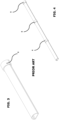
- the products which can be obtained by these technologies can have only very simple cross-sections, provided with a central symmetry and without deep convexities and concavities - on which a correct deposition of reinforcing fibres during the rotation of a rotating mandrel A would be impossible - i.e., essentially circular ( Fig. 1 ) or semicircular cross-sections, such as D-shaped cross-sections ( Fig. 2 ).
- Pull-winding technology normally provides for a carbon fibre lamination procedure according to a typical sequence of fibre layers laid in succession on a rotating mandrel A. As illustrated in Fig. 1 , starting from the tubular element inner diameter, the following fibre layers are formed on mandrel A:
- pull-winding technology involves several drawbacks which limit its field of application. Among them, not particularly high (typically 0.3-0.4 m/min) process speed, single-chain production plant, high criticality in maintaining and continuously monitoring the stringent aesthetic requirements with possibly high consequent reject, and, finally, long times for development and fine-tuning of tubular elements having a different cross-section or new lamination modes.
- the pull-winding technology hardly allows to maintain thickness according to specifications (around 1 mm) for larger sizes and diameters (over 30-35 mm) with a relative efficiency decay, as far as regard the constancy along the circumference of the moment of inertia, compared to extruded aluminium or composite material tubular elements manufactured by wrapping technology.
- the base technology of pultrusion i.e. a technology without the 'winder' equipment which carries out the continuous helical winding of the reinforcing fibres
- hypotheses of alternative solutions through the additional use of carbon fibre tapes/fabric bands inserted inside or outside the bundles of unidirectional fibre also have a high risk of reject, due to the thin thickness of the product, both in the areas of possible shortage or overlapping of material, and for the high aesthetic standards expected in the sector which do not allow lack of evenness or other visible surface irregularities.
- the object of the present invention is therefore to develop a process for manufacturing a non-circular tubular element of composite material according to a new concept, which process allows to overcome the typical drawbacks highlighted above of the known manufacturing processes, and can also be used for manufacturing tubular elements having a complex non-circular cross-section possibly including also edges, convexities, concavities or asymmetries, while maintaining high thickness evenness of the artifact over the entire cross-section, and excellent surface finish.
- a fully innovative process solution has been identified, to solve the problem highlighted above, which solution provides for a discontinuous construction method of the composite tubular element.
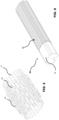
- a single braided sleeve structure 10 of multi-directional carbon fibre is mainly used and, in particular, a triaxial braided sleeve comprising both fibres in the longitudinal direction and fibres in different oblique directions, previously obtained as a semi-finished product through a manufacturing technology on a braiding machine.
- the braided sleeve 10 of triaxial carbon fibre comprises fibres 11 in the longitudinal direction and fibres 12 and 13 in two directions symmetrically angled to said longitudinal direction, for example +/- 45°.
- the diameter of the triaxial braided sleeve 10 is so determined that the braided sleeve side surface corresponds to the development of the tubular element specific cross-section being designed from time to time.
- Semi-finished braided sleeve products of this type are already known and available for several years on the market of composite material products, although for uses in completely different fields of application from the object of the present invention.
- the manufacturing cost of these triaxial braided sleeve semi-finished products is higher than that of the basic fibres wound in coils used in the pull-winding technique, the triaxial braided sleeve is economically competitive for large quantities and has a relatively low impact on the overall cost of the product, considering the relatively small dimensions of the manufactured tubular elements and the use of a single braided sleeve to form, by a simple covering operation of a support mandrel M, the entire tubular element being manufactured.
- the particular method of laminating tubular elements with non-circular cross-section allows to guarantee good axial rigidity and high compressive strength and torsional rigidity of the thus obtained artifact, as well as to maintain a constant thin thickness of the product along the entire cross-section - a thickness of 1 mm is a standard value in the sector, but the manufacturing process of the invention also allows lower thicknesses, for example of 0.8 mm, to be obtained - with cross dimensions of the artifacts in the range of 15-25 mm, for smaller cross-sections, and up to 40-50 mm for larger cross-sections.
- the preferred manufacturing technology for the production of tubular elements with non-circular cross-section is the known resin transfer moulding (RTM) technology, wherein a consolidated preform of carbon fibre arranged on a support mandrel M is placed in a mould, which is closed and placed under vacuum, - and a suitable resin formulation - generally of a thermosetting type, typically an epoxy or polyurethane resin - is injected under pressure inside the mould using an injection machine which mixes the resin components and the catalyst immediately before the injection.
- RTM resin transfer moulding
- the RTM technology allows to overcome all the manufacturing limits of the current production technologies described above.
- the RTM technology allows the integration of a very rapid preliminary preparation step, wherein the operator simply performs a quick positioning of the triaxial braided sleeve 10 onto a metal mandrel A whose outer cross-section corresponds to the desired inner cross-section of the tubular element being manufactured - the mandrel A being suitably cleaned and pretreated with a release agent - with a subsequent injection moulding step under pressure of the thermosetting resin inside a mould whose inner cross-section corresponds to the desired final outer cross-section of the tubular element, inside which the mandrel A is positioned.
- the injection mould is a multiple mould S like that schematically illustrated in Fig.
- the various aforesaid cavities are all connected to a single input channel 14 of the thermosetting resin.
- the length of the multiple cavities of the mould S is preferably an integer multiple of the finished lengths of the tubular elements required by the market (for example from 300 to 600 mm), and can therefore have a development from 900 to 1500 mm, so as to allow the formation of raw rods of tubular element that are a multiple, from double to five times, of the finished length of the requested product, so as to minimize any processing reject.
- the braided sleeve 10 is preferably fixed and held in the correct position onto the mandrel M by means of appropriate, typically spray-applied, liquid fixing agents which guarantee its good consolidation and accurate dimensional stability during the resin impregnation and polymerization process.
- the step of coating the mandrels M with the braided sleeve 10 can be carried out simultaneously with the step of moulding a previous group of coated mandrels, simply by doubling the number of available mandrels M.
- the RTM manufacturing technology generally is characterised by high production capacity, ease of automation, excellent repeatability of the features of the finished product, and also wide flexibility in case of any variation of the type of product (new cross-sections and new moulds can be easily implemented and made operational), or of the specific configuration of the composite laminate.
- the outer aesthetic finish of the artifacts obtained with the process of the invention is easily modified (from a braided finish to a homogeneous finish), by adding a layer of carbon (or other materials, for example TNT) non-woven fabric externally wrapped onto the triaxial carbon fibre braided sleeve 10.
- This material must be easily draped over the specific section of the tubular element being processed, by selecting appropriate weights of the non-woven fabric, and a suitable binder. Since the non-woven fabric layer has the consistency of a veil, once it is resin-impregnated and polymerized in the mould the final joint line is not visible and this improves the aesthetic appearance of the product.
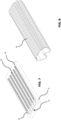
- a thin layer (for example 0.2-0.3 mm) of unidirectional carbon fibre tape 15 is inserted onto the mandrel M, in addition to the braided sleeve 10.
- the thin layer of unidirectional carbon fibre tape 15 can be arranged both inside and outside ( Figs. 9 and 10 ) the braided sleeve 10, also as a semi-finished component pre-consolidated with a binder.
- the unidirectional semi-finished component can include a standard high-strength fibre, or even a partial or total presence of very high modulus pitch fibre, in the case of specific requests for particularly high axial rigidity of the tubular element.
- the triaxial braided sleeve 10 can be brought to a minimum thickness, equal to approximately 0.8 mm, to have a total thickness of the tubular element not greater than 1-1.1 mm.
- the triaxial sleeve 10 consists of two distinct elements rather than a single element, namely, a first unidirectional element with longitudinal fibres and a second biaxial sleeve element with fibres arranged according to two symmetrical inclinations.
- These two elements can be distinct elements, and in this case they are placed in succession and in the desired order onto the mandrel M, or they can be already pre-formed by the braiding machine as two distinct but partially mutually interlaced elements, and in this case the insertion onto the mandrel M takes place in a single operation as in the previous embodiment.
- This structure of the triaxial sleeve made up of two distinct elements makes it possible to increase the proportion of unidirectional fibres compared to the angled fibres, and thus obtain higher axial rigidity of the tubular element.
- tubular element is not provided with concavities or undercut areas and has therefore a lower shape rigidity in the transverse direction
- a further embodiment of the invention is particularly preferred, wherein a thin layer (for example 0.2-0.3 mm) of helical fibres with an angle close to 90° with respect to the longitudinal axis is preliminarily wound onto the mandrel M by winding technology; subsequently, onto this first layer of helical fibres the braided sleeve 10 is inserted - as a single sleeve of the triaxial type or, alternatively, as a sleeve made up of two superimposed elements, the inner one being unidirectional with longitudinal fibres and the outer one being a biaxial sleeve - and then the mandrel is sent to the resin impregnation and moulding steps.
- the tubular elements according to this embodiment feature a very high transversal rigidity, even when formed with very low thicknesses (around 1 mm).
- the manufacturing process according to the present invention also shows another significant advantage compared to the main technology currently in use, i.e. pull-winding technology, as it allows the production of artifacts that do not necessarily have constant cross-section.
- thickened areas can be easily integrated, for example locking collars also made in advance with rings of braided sleeve 10 or strips of carbon fabric wrapped in predetermined limited areas of the mandrel M.
- the manufacturing process according to the invention may involve some drawbacks compared to continuous technologies such as pultrusion or pull-winding technologies, which drawbacks can however be easily overcome.
- the configuration of the moulded tubular element can show at one or two points of its -cross-section (i.e., in correspondence with the joint lines of the base mould with the lid mould) two resin burrs which coincide with a longitudinal, resin feeding channel.
- the minimization of the thickness of this resin edge is provided in the process fine-tuning step, to reduce the extent of the burr and the need for its removal, as well as to eliminate the need for a subsequent painting step.
- the other relevant critical aspect in relation to the manufacturing process of the invention, concerns some intermediate steps, such as the cleaning of the moulds S, and some additional steps after the operation of mould impregnation such as, for example, the steps of extraction and cleaning of the mandrels M. Both these additional steps can be managed in parallel in the process and/or be automated; to free these additional steps from the actual moulding process it is obviously possible to use a third additional group of mandrels M.
- the versatility of the manufacturing process of the invention potentially allows to produce multiple raw tubes (from double to five times the length of use) even with shorter lengths than the maximum defined by the cavities provided in the mould S. This is to avoid rejects in case of different types of lengths of use.
- a shorter preform can be easily prepared on the mandrel M and a low-cost filler can be possibly used on the cavity portion which is left fibre-free, or a (plastic or metal) insert having a cross-section corresponding to that of the tubular element being processed can be used.
- the use of pressurized air chambers inside the mould can be considered, to avoid the relevant extraction and cleaning steps of the mandrels M.
- a further technology allowing a product evolution - alternative to the RTM process but still involving the use of a carbon triaxial braided sleeve 10 as the main reinforcing part - provides a thermoplastic matrix composite, wherein the semi-finished component of the braided sleeve 10 already has the polymeric matrix component in the form of twisted threads on the carbon fibre (co-mingling) or of polymer powder dispersed thereon (powdering).
- the manufacturing technique is more closely associated with the already described application with inner air chamber during the moulding step, which moulding therefore occurs by compression and not by injection.
- the tubular element for camera tripods with a complex, non-circular cross-section made in composite material mainly consisting of braided sleeve reinforcement of triaxial carbon fibres, preferably manufactured by resin injection technology under pressure into a closed mould under vacuum, compared to conventional techniques: provides weight minimization for various cross-sections and sizes; satisfactorily addresses the stresses from axial, torsional and radial compression loads, in terms of resistance and reduced strains; allows a high standard aesthetic finish that is also easily modifiable or customizable; and, finally, features economic competitiveness and production capacity, in line with the market expectations about the evolution of these products.
Landscapes
- Engineering & Computer Science (AREA)
- Mechanical Engineering (AREA)
- Chemical & Material Sciences (AREA)
- Composite Materials (AREA)
- Textile Engineering (AREA)
- Robotics (AREA)
- Moulding By Coating Moulds (AREA)
Applications Claiming Priority (1)
| Application Number | Priority Date | Filing Date | Title |
|---|---|---|---|
| IT102023000005415A IT202300005415A1 (it) | 2023-03-22 | 2023-03-22 | Processo di produzione di un elemento tubolare di materiale composito a sezione non circolare, specialmente per treppiedi di macchine fotografiche, ed elemento tubolare di materiale composito a sezione non circolare prodotto con detto processo |
Publications (2)
| Publication Number | Publication Date |
|---|---|
| EP4434733A2 true EP4434733A2 (de) | 2024-09-25 |
| EP4434733A3 EP4434733A3 (de) | 2024-10-16 |
Family
ID=86657631
Family Applications (1)
| Application Number | Title | Priority Date | Filing Date |
|---|---|---|---|
| EP24164774.2A Withdrawn EP4434733A3 (de) | 2023-03-22 | 2024-03-20 | Verfahren zur herstellung eines nichtkreisförmigen rohrförmigen verbundelementes, insbesondere für kamera-tripodes, und so hergestelltes nichtkreisförmiges rohrförmiges verbundelement |
Country Status (3)
| Country | Link |
|---|---|
| US (1) | US20240316883A1 (de) |
| EP (1) | EP4434733A3 (de) |
| IT (1) | IT202300005415A1 (de) |
Families Citing this family (1)
| Publication number | Priority date | Publication date | Assignee | Title |
|---|---|---|---|---|
| CN119369764A (zh) * | 2024-12-27 | 2025-01-28 | 江苏高路复合材料有限公司 | 一种复合材料制备的内凹零件及其制备方法 |
Citations (2)
| Publication number | Priority date | Publication date | Assignee | Title |
|---|---|---|---|---|
| US20100160128A1 (en) | 2008-12-22 | 2010-06-24 | Mueller Martini Holding Ag | Roller for a printing machine and method for manufacturing the roller |
| US20200139644A1 (en) | 2018-11-02 | 2020-05-07 | The Boeing Company | Composite structures constructed of wound tubular braiding |
Family Cites Families (1)
| Publication number | Priority date | Publication date | Assignee | Title |
|---|---|---|---|---|
| DE102017210814A1 (de) * | 2017-06-27 | 2018-12-27 | Bayerische Motoren Werke Aktiengesellschaft | Verfahren und Stützkern zur Herstellung einer Faserverbundpreform für ein Faserverbundbauteil |
-
2023
- 2023-03-22 IT IT102023000005415A patent/IT202300005415A1/it unknown
-
2024
- 2024-03-20 EP EP24164774.2A patent/EP4434733A3/de not_active Withdrawn
- 2024-03-22 US US18/613,516 patent/US20240316883A1/en active Pending
Patent Citations (2)
| Publication number | Priority date | Publication date | Assignee | Title |
|---|---|---|---|---|
| US20100160128A1 (en) | 2008-12-22 | 2010-06-24 | Mueller Martini Holding Ag | Roller for a printing machine and method for manufacturing the roller |
| US20200139644A1 (en) | 2018-11-02 | 2020-05-07 | The Boeing Company | Composite structures constructed of wound tubular braiding |
Also Published As
| Publication number | Publication date |
|---|---|
| EP4434733A3 (de) | 2024-10-16 |
| IT202300005415A1 (it) | 2024-09-22 |
| US20240316883A1 (en) | 2024-09-26 |
Similar Documents
| Publication | Publication Date | Title |
|---|---|---|
| EP3668725B1 (de) | Felgenfaserarchitektur für ein verbundrad | |
| US8444900B2 (en) | Method and system for forming composite geometric support structures | |
| US20120305173A1 (en) | Process for manufacturing a connecting rod made of a composite having a localized overthickness | |
| TWI624599B (zh) | 編織預成形體總成及製造編織預成形體之方法 | |
| EP3107718B1 (de) | Faserverstärkte polymermatrixverbundrohre | |
| US8801992B2 (en) | Process for manufacturing a structural part made of an organic matrix composite and part obtained | |
| US9528203B2 (en) | Conformable braid | |
| CN105952981A (zh) | 拉挤管材及其制备方法与制造设备 | |
| KR20110002009A (ko) | 복합재 구조의 강화를 위한 프리폼과 이의 제조방법 | |
| EP4434733A2 (de) | Verfahren zur herstellung eines nichtkreisförmigen rohrförmigen verbundelementes, insbesondere für kamera-tripodes, und so hergestelltes nichtkreisförmiges rohrförmiges verbundelement | |
| CN113898798A (zh) | 一种抗内压纤维编织缠绕拉挤复合管及其制备方法 | |
| CN210126324U (zh) | 一种新型高强度纤维拉挤管道 | |
| US20130105079A1 (en) | Method for producing a mechanical member from composite material, having an improved mechanical performance under traction-compression and bending | |
| US12319014B2 (en) | Fibre-reinforced composite tubular shafts and manufacture thereof | |
| WO2017151603A1 (en) | Methods for fabricating preforms for high performance ultra-long fiber reinforced thermoplastic tubing | |
| EP4628287A1 (de) | Verbundstrukturen | |
| CN115750563A (zh) | 一种复合材料预埋连接件及其加工方法 |
Legal Events
| Date | Code | Title | Description |
|---|---|---|---|
| PUAI | Public reference made under article 153(3) epc to a published international application that has entered the european phase |
Free format text: ORIGINAL CODE: 0009012 |
|
| STAA | Information on the status of an ep patent application or granted ep patent |
Free format text: STATUS: THE APPLICATION HAS BEEN PUBLISHED |
|
| PUAL | Search report despatched |
Free format text: ORIGINAL CODE: 0009013 |
|
| AK | Designated contracting states |
Kind code of ref document: A2 Designated state(s): AL AT BE BG CH CY CZ DE DK EE ES FI FR GB GR HR HU IE IS IT LI LT LU LV MC ME MK MT NL NO PL PT RO RS SE SI SK SM TR |
|
| AK | Designated contracting states |
Kind code of ref document: A3 Designated state(s): AL AT BE BG CH CY CZ DE DK EE ES FI FR GB GR HR HU IE IS IT LI LT LU LV MC ME MK MT NL NO PL PT RO RS SE SI SK SM TR |
|
| RIC1 | Information provided on ipc code assigned before grant |
Ipc: B29L 23/00 20060101ALN20240912BHEP Ipc: D04C 3/00 20060101ALN20240912BHEP Ipc: B29K 105/08 20060101ALN20240912BHEP Ipc: B29C 70/20 20060101ALI20240912BHEP Ipc: B29C 70/44 20060101ALI20240912BHEP Ipc: B29C 70/22 20060101ALI20240912BHEP Ipc: B29B 11/16 20060101ALI20240912BHEP Ipc: B29C 70/38 20060101ALI20240912BHEP Ipc: B29C 70/24 20060101AFI20240912BHEP |
|
| STAA | Information on the status of an ep patent application or granted ep patent |
Free format text: STATUS: THE APPLICATION IS DEEMED TO BE WITHDRAWN |
|
| 18D | Application deemed to be withdrawn |
Effective date: 20250417 |