EP4434577A1 - Particle beam irradiation system and particle beam irradiation method - Google Patents
Particle beam irradiation system and particle beam irradiation method Download PDFInfo
- Publication number
- EP4434577A1 EP4434577A1 EP23201109.8A EP23201109A EP4434577A1 EP 4434577 A1 EP4434577 A1 EP 4434577A1 EP 23201109 A EP23201109 A EP 23201109A EP 4434577 A1 EP4434577 A1 EP 4434577A1
- Authority
- EP
- European Patent Office
- Prior art keywords
- charged particle
- particle beam
- beam irradiation
- apparatuses
- transported
- Prior art date
- Legal status (The legal status is an assumption and is not a legal conclusion. Google has not performed a legal analysis and makes no representation as to the accuracy of the status listed.)
- Pending
Links
Images


Classifications
-
- H—ELECTRICITY
- H05—ELECTRIC TECHNIQUES NOT OTHERWISE PROVIDED FOR
- H05H—PLASMA TECHNIQUE; PRODUCTION OF ACCELERATED ELECTRICALLY-CHARGED PARTICLES OR OF NEUTRONS; PRODUCTION OR ACCELERATION OF NEUTRAL MOLECULAR OR ATOMIC BEAMS
- H05H7/00—Details of devices of the types covered by groups H05H9/00, H05H11/00, H05H13/00
- H05H7/06—Two-beam arrangements; Multi-beam arrangements storage rings; Electron rings
-
- H—ELECTRICITY
- H05—ELECTRIC TECHNIQUES NOT OTHERWISE PROVIDED FOR
- H05H—PLASMA TECHNIQUE; PRODUCTION OF ACCELERATED ELECTRICALLY-CHARGED PARTICLES OR OF NEUTRONS; PRODUCTION OR ACCELERATION OF NEUTRAL MOLECULAR OR ATOMIC BEAMS
- H05H7/00—Details of devices of the types covered by groups H05H9/00, H05H11/00, H05H13/00
- H05H7/001—Arrangements for beam delivery or irradiation
-
- A—HUMAN NECESSITIES
- A61—MEDICAL OR VETERINARY SCIENCE; HYGIENE
- A61N—ELECTROTHERAPY; MAGNETOTHERAPY; RADIATION THERAPY; ULTRASOUND THERAPY
- A61N5/00—Radiation therapy
- A61N5/10—X-ray therapy; Gamma-ray therapy; Particle-irradiation therapy
- A61N5/1077—Beam delivery systems
- A61N5/1079—Sharing a beam by multiple treatment stations
-
- G—PHYSICS
- G21—NUCLEAR PHYSICS; NUCLEAR ENGINEERING
- G21K—HANDLING OF PARTICLES OR IONISING RADIATION NOT OTHERWISE PROVIDED FOR; IRRADIATION DEVICES; GAMMA RAY OR X-RAY MICROSCOPES
- G21K1/00—Arrangements for handling particles or ionising radiation, e.g. focusing or moderating
-
- G—PHYSICS
- G21—NUCLEAR PHYSICS; NUCLEAR ENGINEERING
- G21K—HANDLING OF PARTICLES OR IONISING RADIATION NOT OTHERWISE PROVIDED FOR; IRRADIATION DEVICES; GAMMA RAY OR X-RAY MICROSCOPES
- G21K5/00—Irradiation devices
-
- H—ELECTRICITY
- H05—ELECTRIC TECHNIQUES NOT OTHERWISE PROVIDED FOR
- H05H—PLASMA TECHNIQUE; PRODUCTION OF ACCELERATED ELECTRICALLY-CHARGED PARTICLES OR OF NEUTRONS; PRODUCTION OR ACCELERATION OF NEUTRAL MOLECULAR OR ATOMIC BEAMS
- H05H7/00—Details of devices of the types covered by groups H05H9/00, H05H11/00, H05H13/00
- H05H7/04—Magnet systems, e.g. undulators, wigglers; Energisation thereof
-
- A—HUMAN NECESSITIES
- A61—MEDICAL OR VETERINARY SCIENCE; HYGIENE
- A61N—ELECTROTHERAPY; MAGNETOTHERAPY; RADIATION THERAPY; ULTRASOUND THERAPY
- A61N5/00—Radiation therapy
- A61N5/10—X-ray therapy; Gamma-ray therapy; Particle-irradiation therapy
- A61N2005/1085—X-ray therapy; Gamma-ray therapy; Particle-irradiation therapy characterised by the type of particles applied to the patient
- A61N2005/1087—Ions; Protons
-
- H—ELECTRICITY
- H05—ELECTRIC TECHNIQUES NOT OTHERWISE PROVIDED FOR
- H05H—PLASMA TECHNIQUE; PRODUCTION OF ACCELERATED ELECTRICALLY-CHARGED PARTICLES OR OF NEUTRONS; PRODUCTION OR ACCELERATION OF NEUTRAL MOLECULAR OR ATOMIC BEAMS
- H05H7/00—Details of devices of the types covered by groups H05H9/00, H05H11/00, H05H13/00
- H05H7/04—Magnet systems, e.g. undulators, wigglers; Energisation thereof
- H05H2007/045—Magnet systems, e.g. undulators, wigglers; Energisation thereof for beam bending
-
- H—ELECTRICITY
- H05—ELECTRIC TECHNIQUES NOT OTHERWISE PROVIDED FOR
- H05H—PLASMA TECHNIQUE; PRODUCTION OF ACCELERATED ELECTRICALLY-CHARGED PARTICLES OR OF NEUTRONS; PRODUCTION OR ACCELERATION OF NEUTRAL MOLECULAR OR ATOMIC BEAMS
- H05H2277/00—Applications of particle accelerators
- H05H2277/10—Medical devices
- H05H2277/11—Radiotherapy
Definitions
- the present invention relates to a particle beam irradiation system and a particle beam irradiation method.
- JP-2005-302734-A discloses an accelerator system for accelerating an ion beam by a post-accelerator including a synchrotron, and supplying a high-energy ion beam to a plurality of irradiation rooms to perform therapy.
- a post-accelerator including a synchrotron
- one post-accelerator and a plurality of treatment rooms (irradiation rooms) are connected to each other through a transport line.
- the method capable of performing the beam irradiation in a plurality of irradiation rooms at the same time has already been invented.
- a plurality of accelerators cannot be driven independently of each other, and an accelerator from which a particle beam is to be transported is allocated to each irradiation room. Therefore, if one of the accelerators fails, one or more corresponding irradiation rooms are also disabled. That is, if an accelerator fails, there is always an irradiation room that cannot be used, and thus, the throughput upon failure of the accelerator drops significantly in the above-mentioned method.
- a particle beam irradiation system including two or more charged particle beam generation apparatuses capable of operating independently of each other, a beam transport line that transports charged particle beams generated by the charged particle beam generation apparatuses, and/or two or more beam irradiation apparatuses to which the charged particle beams are transported through the beam transport line.
- any one of the beam irradiation apparatuses is configured such that the charged particle beams from a plurality of the charged particle beam generation apparatuses can be transported thereto, and the charged particle beams are simultaneously transported from the plurality of charged particle beam generation apparatuses to corresponding ones of the different beam irradiation apparatuses.
- simultaneous irradiation can be performed by a plurality of beam irradiation apparatuses, and throughput reduction upon failure of a charged particle beam generation apparatus can be minimized.
- FIG. 1 is a schematic view depicting the particle beam irradiation system according to the present embodiment.
- a particle beam irradiation system 100 includes a charged particle beam generation apparatus 1, a beam transport line 2, and a beam irradiation apparatus 3.
- a particle beam irradiation system includes a charged particle beam generation apparatus, a beam transport line, and a beam irradiation apparatus.
- the charged particle beam generation apparatus 1 includes an ion source (not depicted), a pre-accelerator 11, and a circular accelerator (synchrotron) 12, and generates a charged particle beam 32.
- a synchrotron is described as an example of the circular accelerator 12, another accelerator such as a cyclotron may be used.
- the ion source is connected to the upstream side of the pre-accelerator 11, and the circular accelerator 12 is connected to the downstream side of the pre-accelerator 11.
- the particle beam irradiation system 100 includes a plurality of charged particle beam generation apparatuses 1.
- the beam transport line 2 is connected to the downstream side of the charged particle beam generation apparatus 1, and connects the charged particle beam generation apparatus 1 and the beam irradiation apparatus 3 to each other through a vacuum pipe 5.
- a plurality of bending magnets 6 are provided on the vacuum pipe 5.
- the charged particle beam 32 generated by the charged particle beam generation apparatus 1 is introduced to the respective beam irradiation apparatuses 3 in irradiation rooms by the bending magnets 6 through the beam transport line 2.
- Each of the bending magnets 6 is arranged such that a pair of electromagnets face each other across the vacuum pipe 5.
- a magnetic field is generated between the pair of electromagnets according to electric energy applied to the bending magnet 6 and changes the advancing direction of the charged particle beam passing between the electromagnets.
- the vacuum pipe 5 at positions where the bending magnets 6 are arranged has such a structure as to enable the charged particle beam to either advance straightforwardly or bend in a perpendicular direction.
- the intensity of the magnetic field to be applied to the bending magnet 6 is controlled, the charged particle beam can be made to advance straightforwardly or bend in the perpendicular direction.
- a plurality of beam irradiation apparatuses 3 can be provided in the particle beam irradiation system 100 according to the present embodiment.
- the charged particle beam 32 is introduced to corresponding one of the beam irradiation apparatuses 3 when the bending magnet 6 which is disposed at a suitable position from among the plurality of bending magnets 6 on the beam transport line 2 is controlled.
- the beam irradiation apparatus 3 is an apparatus for irradiating an affected part of a patient 42 who is standing by in a treatment room 4, with the charged particle beam 32 transported through the beam transport line 2.
- the beam irradiation apparatus 3 includes a treatment table 41 on which the patient 42 is to be placed thereon, an irradiation nozzle (nozzle device) 31, and a rotation gantry 30.
- a fixed irradiation type (two-dimensional plane type) beam irradiation apparatus that does not include the rotation gantry 30 may be used.
- FIG. 2 is a block diagram depicting an example of a minimum configuration of the particle beam irradiation system 100.
- the minimum configuration of the particle beam irradiation system includes two charged particle beam generation apparatuses 1-1 and 1-2 and two beam irradiation apparatuses 3-1 and 3-2 as depicted in FIG. 2 .
- the beam irradiation apparatuses 3-1 and 3-2 are installed in the separate treatment rooms 4 ( FIG. 1 ).
- the charged particle beam generation apparatuses 1-1 and 1-2 have the same structure as that of the charged particle beam generation apparatus 1 depicted in FIG. 1
- the beam irradiation apparatuses 3-1 and 3-2 have the same structure as that of the beam irradiation apparatus 3 depicted in FIG. 1 .
- the charged particle beam generation apparatuses 1-1 and 1-2 can be driven independently of each other, and even if one of the charged particle beam generation apparatuses 1-1 and 1-2 fails, the other one of the charged particle beam generation apparatuses 1-1 and 1-2 can operate. That is, the two charged particle beam generation apparatuses are physically separated apparatuses, and they are controlled so as not to rely on each other. Further, the types of ion sources handled by the two charged particle beam generation apparatuses 1-1 and 1-2 are not limited to particular ones, and may be the same nuclear species or different nuclear species.
- charged particle beams from the charged particle beam generation apparatuses 1-1 and 1-2 can be transported to either the beam irradiation apparatus 3-1 or 3-2.
- charged particle beams from a plurality of charged particle beam generation apparatuses are not simultaneously transported to one beam irradiation apparatus.
- bending magnets 61-1 and 61-2 and a bending magnet 62-1 are provided on the beam transport line 2.
- Each of the bending magnets 61-1 and 61-2 and the bending magnet 62-1 has the same structure as that of the bending magnets 6 of FIG. 1 .
- a charged particle beam generated by the charged particle beam generation apparatus 1-1 can be transported to the beam irradiation apparatus 3-1 through the bending magnets 61-1 and 62-1 on the beam transport line 2. Further, the charged particle beam generated by the charged particle beam generation apparatus 1-1 can be transported to the beam irradiation apparatus 3-2 through the bending magnets 61-1 and 61-2 on the beam transport line 2. Meanwhile, a charged particle beam generated by the charged particle beam generation apparatus 1-2 can be transported to the beam irradiation apparatus 3-1 through the bending magnet 62-1 on the beam transport line 2.
- the particle beam irradiation system 100 includes an overall controller 21 that outputs a control signal to the charged particle beam generation apparatuses 1-1 and 1-2 and the bending magnets 61-1, 61-2, and 62-1 to control operations of the respective charged particle beam generation apparatuses and the respective bending magnets.
- a storage unit 22 in which a relation between energy and a magnetic field is stored is connected to the overall controller 21.
- the acceleration of a charged particle depends upon the intensity of the magnetic field. Generally, in a case where a charged particle has an equal charged amount, as the magnetic field intensity increases, the energy that the charged particle receives from the magnetic field increases, and the kinetic energy of the charged particle (acceleration) increases.
- the overall controller 21 outputs a command to an undepicted controller provided for the bending magnet.
- the controller for the bending magnet may be provided for each bending magnet or provided for each group (for example, a group determined taking a transport path of a charged particle beam into consideration) of a plurality of bending magnets. According to the command from the overall controller 21, the controller for the bending magnet supplies electric energy to the corresponding bending magnet to generate a magnetic field and perform switching of the beam transport.
- the charged particle beam generated by the charged particle beam generation apparatus 1-1 changes its advancing direction to a perpendicular direction at the bending magnet 61-1 and is transported to the beam irradiation apparatus 3-1 through the bending magnet 62-1. Further, the charged particle beam generated by the charged particle beam generation apparatus 1-1 is transported to the beam irradiation apparatus 3-2 through the bending magnet 61-1 and the bending magnet 61-2. Meanwhile, the charged particle beam generated by the charged particle beam generation apparatus 1-2 changes its advancing direction to a perpendicular direction at the bending magnet 62-1 and is transported to the beam irradiation apparatus 3-1.
- the particle beam irradiation system 100 includes an undepicted controller for controlling operations of the beam irradiation apparatuses 3-1 and 3-2.
- This controller controls the operations of the beam irradiation apparatuses 3-1 and 3-2 according to an engineer's command or on the basis of a condition set in advance, to irradiate a target position of a patient 42 on the treatment table 41 in each treatment room 4 with a charged particle beam.
- a first charged particle beam can be transported from a first charged particle beam generation apparatus to a first beam irradiation apparatus, and concurrently with this, a second charged particle beam can be transported from a second charged particle beam generation apparatus to a second beam irradiation apparatus through a shared beam transport line.
- charged particle beams can be applied concurrently by a plurality of beam irradiation apparatuses (treatment rooms).
- the number of charged particle beam generation apparatuses, the number of beam irradiation apparatuses, the arrangement of them, and so forth differ among different facilities.
- a particle beam irradiation system that includes two charged particle beam generation apparatuses and three beam irradiation apparatuses is described with reference to FIG. 3 .
- FIG. 3 is a block diagram depicting another example of the configuration of the particle beam irradiation system according to the present embodiment.
- a particle beam irradiation system 100A depicted in FIG. 3 typically includes two charged particle beam generation apparatuses 1-1 and 1-2 and three beam irradiation apparatuses 3-1, 3-2, and 3-3.
- the beam irradiation apparatuses 3-1 to 3-3 are installed in the separate treatment rooms 4 ( FIG. 1 ).
- the charged particle beam generation apparatuses 1-1 and 1-2 have the same structure as that of the charged particle beam generation apparatus 1 depicted in FIG. 1
- the beam irradiation apparatuses 3-1, 3-2, and 3-3 have the same structure as that of the beam irradiation apparatus 3 depicted in FIG. 1 .
- the charged particle beam generation apparatuses 1-1 and 1-2 can be driven independently of each other, and even if one of the charged particle beam generation apparatuses 1-1 and 1-2 fails, the other charged particle beam generation apparatus can operate.
- the types of ion sources handled by the two charged particle beam generation apparatuses 1-1 and 1-2 are not limited to particular ones, and may be the same nuclear species or different nuclear species.
- the particle beam irradiation system 100A depicted in FIG. 3 further includes, on the beam transport line 2, bending magnets 61-1, 61-2, and 61-3 and bending magnets 62-1 and 62-2.
- Each of the bending magnets 61-1 to 61-3 and 62-1 to 62-2 has the same structure as that of the bending magnet 6 of FIG. 1 .
- bending magnets 61 in a case where there is no necessity to distinguish the bending magnets from one another, they are simply referred to as bending magnets 61.
- the particle beam irradiation system 100A is configured such that charged particle beams from the plurality of charged particle beam generation apparatuses 1-1 and 1-2 can be transported to any one of the beam irradiation apparatuses 3-1, 3-2, and 3-3.
- charged particle beams from a plurality of charged particle beam generation apparatuses are not simultaneously transported to one beam irradiation apparatus.
- a charged particle beam generated by the charged particle beam generation apparatus 1-1 can be transported to the beam irradiation apparatus 3-1 through a vacuum pipe 51-1, the bending magnet 61-1, a vacuum pipe 53-1, the bending magnet 62-1, and a vacuum pipe 53-2 on the beam transport line 2. Further, the charged particle beam generated by the charged particle beam generation apparatus 1-1 can be transported to the beam irradiation apparatus 3-2 through the vacuum pipe 51-1, the bending magnet 61-1, a vacuum pipe 51-2, the bending magnet 61-2, a vacuum pipe 54-1, the bending magnet 62-2, and a vacuum pipe 54-2 on the beam transport line 2.
- the charged particle beam generated by the charged particle beam generation apparatus 1-1 can be transported to the beam irradiation apparatus 3-3 through the vacuum pipe 51-1, the bending magnet 61-1, the vacuum pipe 51-2, the bending magnet 61-2, a vacuum pipe 51-3, the bending magnet 61-3, and a vacuum pipe 55 on the beam transport line 2.
- a charged particle beam generated by the charged particle beam generation apparatus 1-2 can be transmitted to the beam irradiation apparatus 3-1 through a vacuum pipe 52-1, the bending magnet 62-1, and the vacuum pipe 53-2 on the beam transport line 2. Further, the charged particle beam generated by the charged particle beam generation apparatus 1-2 can be transported to the beam irradiation apparatus 3-2 through the vacuum pipe 52-1, the bending magnet 62-1, a vacuum pipe 52-2, the bending magnet 62-2, and the vacuum pipe 54-2 on the beam transport line 2. It is to be noted that the vacuum pipe 52-2 and the vacuum pipe 55 may be connected to each other.
- the particle beam irradiation system includes two or more charged particle beam generation apparatuses that can be driven independently of each other, a beam transport line that transports charged particle beams generated by the charged particle beam generation apparatuses, and two or more beam irradiation apparatuses to which the charged particle beams are transported through the beam transport line.
- the particle beam irradiation system is configured such that charged particle beams from a plurality of charged particle beam generation apparatuses can be transported to any one of the beam irradiation apparatuses, and the charged particle beams from the plurality of charged particle beam generation apparatuses are simultaneously transported to corresponding ones of the different beam irradiation apparatuses.
- the charged particle beam generation apparatus from which a charged particle beam can be transmitted to the beam irradiation apparatus is not limited to a particular one, and a plurality of charged particle beam generation apparatuses are configured to be able to operate independently of each other.
- a plurality of beam irradiation apparatuses can perform simultaneous irradiation, and the number of patients who can receive treatment per hour can be increased.
- reduction of the throughput upon failure of a charged particle beam generation apparatus can be suppressed to the minimum.
- the advancing direction of the first charged particle beam and the advancing direction of the second charged particle beam sometimes intersect in a vacuum pipe at a position (for example, at the bending magnet 62-1) where a bending magnet is arranged on the shared beam transport line.
- the vacuum pipe 53-1 and the vacuum pipe 52-1 that are to be used may be independent of each other or may be common to each other. In other words, the vacuum pipe 53-1 and the vacuum pipe 52-1 may be independent of each other or may be connected to each other.
- the vacuum pipe 52-1 and the vacuum pipe 53-2 that are used when a charged particle beam is to be transported from the charged particle beam generation apparatus 1-2 to the beam irradiation apparatus 3-1 may be independent of each other or may be common to each other.
- the charged particle beam generation apparatus 1-2 fails, in the configuration of FIG. 3 , it is possible to continuously use the beam irradiation apparatuses 3-1 and 3-2 when the charged particle beam generation apparatus 1-1 is used. Therefore, reduction of the throughput when the charged particle beam generation apparatus 1-2 fails can be minimized.
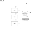
- FIG. 4 is a block diagram depicting an example of a hardware configuration of the overall controller 21.
- a computing machine 70 depicted in FIG. 4 is hardware used as what is generally called a computer.
- the computing machine 70 includes a central processing unit (CPU) 71, a read only memory (ROM)72, a random access memory (RAM) 73, a nonvolatile storage 74, and a communication interface 75 that are individually connected to a bus.
- CPU central processing unit
- ROM read only memory
- RAM random access memory
- nonvolatile storage 74 nonvolatile storage 74
- communication interface 75 that are individually connected to a bus.
- the CPU 71 reads out, from the ROM 72, program codes of software for implementing various functions relating to the present embodiment, loads the program codes into the RAM 73, and executes the program codes. Otherwise, the CPU 71 may read out the program codes directly from the ROM 72 and execute the program codes as they are. It is to be noted that the computing machine 70 may include a processing device such as a micro-processing unit (MPU) in place of the CPU 71.
- MPU micro-processing unit
- Variables, parameters, and so forth generated during the execution of computation processing by the CPU 71 are temporarily written into the RAM 73. It is to be noted that, in a case where the RAM 73 includes a nonvolatile medium, various kinds of information such as temporary communication path information may be stored in the RAM 73.
- the beam transport switching function of the overall controller 21 is implemented by the CPU 71 reading out a program for implementing the function, from the ROM 72, and executing the program. For example, when the overall controller 21 receives a switching command for a charged particle beam generation apparatus and a beam irradiation apparatus from an engineer, the overall controller 21 executes the beam transport switching on the basis of the details of the command.
- a hard disk drive HDD
- SSD solid state drive
- a flexible disk an optical disk
- a magnetooptical disk CD-ROM
- CD-R compact disk readable
- nonvolatile memory card a nonvolatile memory card
- the program is stored in the form of computer-readable program codes, and the CPU 71 sequentially executes operations according to the program codes. That is, the ROM 72 or the nonvolatile storage 74 is used as an example of a computer-readable non-transitory recording medium in which a program to be executed by a computer is stored.
- the function of the storage unit 22 may be implemented by the nonvolatile storage 74.
- the communication interface 75 includes, for example, a communication device for controlling communication to be performed with another apparatus.
- the other apparatus may be, for example, a user interface that accepts a command from an engineer, a controller for a bending magnet, a charged particle beam generation apparatus, or the like.
- a path for serial communication of a multi-drop form such as RS-485 and a communication path that provides a plurality of topologies such as Ethernet (registered trademark) are available.
- a local area network (LAN) or a wide area network (WAN) that are wired communication paths, a radio area network (RAN) that is a wired communication path, and so forth are available.
- a wireless network such as Wi-Fi (registered trademark), a wireless network in a wireless communication infrastructure, and so forth are available, for example.
- the controller for the bending magnet and the controller for the beam irradiation apparatus can have a hardware configuration similar to that of the example depicted in FIG. 4 .
- the CPU 71 executes a computer program for implementing a function of changing the advancing direction of a beam, to implement the function.
- the controller for beam irradiation executes a computer program for implementing a beam irradiation function (beam irradiation position control and so forth), to implement the function.
- control lines and information lines that are considered to be necessary for describing the above-mentioned embodiment are exemplified in the above description, and all control lines or information lines of products are not necessarily depicted. It may be considered that almost all components are connected to one another in practice.
Landscapes
- Engineering & Computer Science (AREA)
- Physics & Mathematics (AREA)
- Health & Medical Sciences (AREA)
- Biomedical Technology (AREA)
- Spectroscopy & Molecular Physics (AREA)
- Plasma & Fusion (AREA)
- Nuclear Medicine, Radiotherapy & Molecular Imaging (AREA)
- Pathology (AREA)
- Radiology & Medical Imaging (AREA)
- Life Sciences & Earth Sciences (AREA)
- Animal Behavior & Ethology (AREA)
- General Health & Medical Sciences (AREA)
- Public Health (AREA)
- Veterinary Medicine (AREA)
- General Engineering & Computer Science (AREA)
- High Energy & Nuclear Physics (AREA)
- Optics & Photonics (AREA)
- Radiation-Therapy Devices (AREA)
- Particle Accelerators (AREA)
Abstract
A particle beam irradiation system (100) according to an aspect of the present invention includes two or more charged particle beam generation apparatuses (1) capable of operating independently of each other, a beam transport line (2) that transports charged particle beams generated by the charged particle beam generation apparatuses (1), and two or more beam irradiation apparatuses (3) to which the charged particle beams are transported through the beam transport line (2). Any one of the beam irradiation apparatuses (3) is configured such that the charged particle beams from a plurality of the charged particle beam generation apparatuses (1) can be transported thereto, and the charged particle beams are simultaneously transported from the plurality of charged particle beam generation apparatuses (1) to corresponding ones of the different beam irradiation apparatuses (3).
Description
- The present invention relates to a particle beam irradiation system and a particle beam irradiation method.
- In particle beam therapy, in order to irradiate a predetermined position with a particle beam as planned, the position of a patient is set before the irradiation. After the position has been set, the patient is not allowed to move and needs to keep the same posture until the beam irradiation is completed. Further, a particle beam cannot be transported from one accelerator to a plurality of irradiation rooms (beam irradiation apparatuses) simultaneously. Therefore, in a case where an accelerator to be used is transporting a particle beam to another irradiation room at the time when the position of the patient has been set, the patient needs to wait until the beam irradiation is completed in the other irradiation room. This decreases the efficiency and also places a burden on the patient. Therefore, there has been invented a method of performing beam irradiation in a plurality of irradiation rooms at the same time.
- For example,
JP-2005-302734-A - As disclosed in
JP-2005-302734-A - In view of the situation described above, there has been demanded a method capable of performing simultaneous irradiation in a plurality of irradiation rooms and also minimizing degradation of the throughput when an accelerator fails.
- In order to solve the problem described above, according to an aspect of the present invention, there is provided a particle beam irradiation system including two or more charged particle beam generation apparatuses capable of operating independently of each other, a beam transport line that transports charged particle beams generated by the charged particle beam generation apparatuses, and/or two or more beam irradiation apparatuses to which the charged particle beams are transported through the beam transport line. In the particle beam irradiation system, any one of the beam irradiation apparatuses is configured such that the charged particle beams from a plurality of the charged particle beam generation apparatuses can be transported thereto, and the charged particle beams are simultaneously transported from the plurality of charged particle beam generation apparatuses to corresponding ones of the different beam irradiation apparatuses.
- According to at least the aspect of the present invention, simultaneous irradiation can be performed by a plurality of beam irradiation apparatuses, and throughput reduction upon failure of a charged particle beam generation apparatus can be minimized.
- Problems, configurations, and advantageous effects other than those described above will be apparent from the following description of an embodiment.
-
-
FIG. 1 is a schematic view depicting a particle beam irradiation system according to an embodiment of the present invention; -
FIG. 2 is a block diagram depicting an example of a minimum configuration of the particle beam irradiation system according to the embodiment of the present invention; -
FIG. 3 is a block diagram depicting another example of the configuration of the particle beam irradiation system according to the embodiment of the present invention; and -
FIG. 4 is a block diagram depicting an example of a hardware configuration of an overall controller according to the embodiment of the present invention. - In the following, an example of a mode for carrying out the present invention (hereinafter referred to as an "embodiment") is described with reference to the accompanying drawings. In the present specification and the accompanying drawings, identical components or components having substantially identical functions are denoted by identical reference characters, and overlapping description thereof is omitted suitably. Further, in a case where a plurality of components have identical or similar functions, different suffixes are sometimes added to the same reference character in the description. In addition, in a case where there is no necessity to distinguish these components from each other, their suffixes are sometimes omitted in the description.
- First, a rough configuration of a particle beam irradiation system according to an embodiment of the present invention is described with reference to
FIG. 1 . -
FIG. 1 is a schematic view depicting the particle beam irradiation system according to the present embodiment. As depicted inFIG. 1 , a particlebeam irradiation system 100 according to the present embodiment includes a charged particlebeam generation apparatus 1, abeam transport line 2, and abeam irradiation apparatus 3. Generally, a particle beam irradiation system includes a charged particle beam generation apparatus, a beam transport line, and a beam irradiation apparatus. - The charged particle
beam generation apparatus 1 includes an ion source (not depicted), a pre-accelerator 11, and a circular accelerator (synchrotron) 12, and generates acharged particle beam 32. Although, in the present embodiment, a synchrotron is described as an example of thecircular accelerator 12, another accelerator such as a cyclotron may be used. The ion source is connected to the upstream side of the pre-accelerator 11, and thecircular accelerator 12 is connected to the downstream side of the pre-accelerator 11. As depicted inFIGS. 2 and3 described later, the particlebeam irradiation system 100 according to the present embodiment includes a plurality of charged particlebeam generation apparatuses 1. - The
beam transport line 2 is connected to the downstream side of the charged particlebeam generation apparatus 1, and connects the charged particlebeam generation apparatus 1 and thebeam irradiation apparatus 3 to each other through a vacuum pipe 5. A plurality ofbending magnets 6 are provided on the vacuum pipe 5. Thecharged particle beam 32 generated by the charged particlebeam generation apparatus 1 is introduced to the respectivebeam irradiation apparatuses 3 in irradiation rooms by thebending magnets 6 through thebeam transport line 2. - Each of the
bending magnets 6 is arranged such that a pair of electromagnets face each other across the vacuum pipe 5. A magnetic field is generated between the pair of electromagnets according to electric energy applied to thebending magnet 6 and changes the advancing direction of the charged particle beam passing between the electromagnets. The vacuum pipe 5 at positions where thebending magnets 6 are arranged has such a structure as to enable the charged particle beam to either advance straightforwardly or bend in a perpendicular direction. Thus, when the intensity of the magnetic field to be applied to thebending magnet 6 is controlled, the charged particle beam can be made to advance straightforwardly or bend in the perpendicular direction. - As depicted in
FIGS. 2 and3 described later, a plurality ofbeam irradiation apparatuses 3 can be provided in the particlebeam irradiation system 100 according to the present embodiment. In a case where a plurality ofbeam irradiation apparatuses 3 are provided, thecharged particle beam 32 is introduced to corresponding one of thebeam irradiation apparatuses 3 when thebending magnet 6 which is disposed at a suitable position from among the plurality ofbending magnets 6 on thebeam transport line 2 is controlled. - The
beam irradiation apparatus 3 is an apparatus for irradiating an affected part of apatient 42 who is standing by in atreatment room 4, with thecharged particle beam 32 transported through thebeam transport line 2. As depicted inFIG. 1 , thebeam irradiation apparatus 3 according to the present embodiment includes a treatment table 41 on which thepatient 42 is to be placed thereon, an irradiation nozzle (nozzle device) 31, and arotation gantry 30. It is to be noted that a fixed irradiation type (two-dimensional plane type) beam irradiation apparatus that does not include therotation gantry 30 may be used. - Next, a minimum configuration of the particle beam irradiation system according to the present embodiment is described with reference to
FIG. 2 . -
FIG. 2 is a block diagram depicting an example of a minimum configuration of the particlebeam irradiation system 100. The minimum configuration of the particle beam irradiation system includes two charged particle beam generation apparatuses 1-1 and 1-2 and two beam irradiation apparatuses 3-1 and 3-2 as depicted inFIG. 2 . The beam irradiation apparatuses 3-1 and 3-2 are installed in the separate treatment rooms 4 (FIG. 1 ). - The charged particle beam generation apparatuses 1-1 and 1-2 have the same structure as that of the charged particle
beam generation apparatus 1 depicted inFIG. 1 , and the beam irradiation apparatuses 3-1 and 3-2 have the same structure as that of thebeam irradiation apparatus 3 depicted inFIG. 1 . The charged particle beam generation apparatuses 1-1 and 1-2 can be driven independently of each other, and even if one of the charged particle beam generation apparatuses 1-1 and 1-2 fails, the other one of the charged particle beam generation apparatuses 1-1 and 1-2 can operate. That is, the two charged particle beam generation apparatuses are physically separated apparatuses, and they are controlled so as not to rely on each other. Further, the types of ion sources handled by the two charged particle beam generation apparatuses 1-1 and 1-2 are not limited to particular ones, and may be the same nuclear species or different nuclear species. - In the present embodiment, charged particle beams from the charged particle beam generation apparatuses 1-1 and 1-2 can be transported to either the beam irradiation apparatus 3-1 or 3-2. However, charged particle beams from a plurality of charged particle beam generation apparatuses are not simultaneously transported to one beam irradiation apparatus.
- Further, in the particle
beam irradiation system 100 depicted inFIG. 2 , bending magnets 61-1 and 61-2 and a bending magnet 62-1 are provided on thebeam transport line 2. Each of the bending magnets 61-1 and 61-2 and the bending magnet 62-1 has the same structure as that of the bendingmagnets 6 ofFIG. 1 . - In the particle
beam irradiation system 100, a charged particle beam generated by the charged particle beam generation apparatus 1-1 can be transported to the beam irradiation apparatus 3-1 through the bending magnets 61-1 and 62-1 on thebeam transport line 2. Further, the charged particle beam generated by the charged particle beam generation apparatus 1-1 can be transported to the beam irradiation apparatus 3-2 through the bending magnets 61-1 and 61-2 on thebeam transport line 2. Meanwhile, a charged particle beam generated by the charged particle beam generation apparatus 1-2 can be transported to the beam irradiation apparatus 3-1 through the bending magnet 62-1 on thebeam transport line 2. - The particle
beam irradiation system 100 includes anoverall controller 21 that outputs a control signal to the charged particle beam generation apparatuses 1-1 and 1-2 and the bending magnets 61-1, 61-2, and 62-1 to control operations of the respective charged particle beam generation apparatuses and the respective bending magnets. - A
storage unit 22 in which a relation between energy and a magnetic field is stored is connected to theoverall controller 21. The acceleration of a charged particle depends upon the intensity of the magnetic field. Generally, in a case where a charged particle has an equal charged amount, as the magnetic field intensity increases, the energy that the charged particle receives from the magnetic field increases, and the kinetic energy of the charged particle (acceleration) increases. - Further, the
overall controller 21 outputs a command to an undepicted controller provided for the bending magnet. The controller for the bending magnet may be provided for each bending magnet or provided for each group (for example, a group determined taking a transport path of a charged particle beam into consideration) of a plurality of bending magnets. According to the command from theoverall controller 21, the controller for the bending magnet supplies electric energy to the corresponding bending magnet to generate a magnetic field and perform switching of the beam transport. - In the example depicted in
FIG. 2 , the charged particle beam generated by the charged particle beam generation apparatus 1-1 changes its advancing direction to a perpendicular direction at the bending magnet 61-1 and is transported to the beam irradiation apparatus 3-1 through the bending magnet 62-1. Further, the charged particle beam generated by the charged particle beam generation apparatus 1-1 is transported to the beam irradiation apparatus 3-2 through the bending magnet 61-1 and the bending magnet 61-2. Meanwhile, the charged particle beam generated by the charged particle beam generation apparatus 1-2 changes its advancing direction to a perpendicular direction at the bending magnet 62-1 and is transported to the beam irradiation apparatus 3-1. - Further, the particle
beam irradiation system 100 includes an undepicted controller for controlling operations of the beam irradiation apparatuses 3-1 and 3-2. This controller controls the operations of the beam irradiation apparatuses 3-1 and 3-2 according to an engineer's command or on the basis of a condition set in advance, to irradiate a target position of a patient 42 on the treatment table 41 in eachtreatment room 4 with a charged particle beam. - In this manner, in the present embodiment, a first charged particle beam can be transported from a first charged particle beam generation apparatus to a first beam irradiation apparatus, and concurrently with this, a second charged particle beam can be transported from a second charged particle beam generation apparatus to a second beam irradiation apparatus through a shared beam transport line.
- In the present embodiment configured as described above, since the respective charged particle beam generation apparatuses have separate transport paths of charged particle beams, charged particle beams can be applied concurrently by a plurality of beam irradiation apparatuses (treatment rooms).
- The number of charged particle beam generation apparatuses, the number of beam irradiation apparatuses, the arrangement of them, and so forth differ among different facilities. Here, as a typical example, a particle beam irradiation system that includes two charged particle beam generation apparatuses and three beam irradiation apparatuses is described with reference to
FIG. 3 . -
FIG. 3 is a block diagram depicting another example of the configuration of the particle beam irradiation system according to the present embodiment. A particlebeam irradiation system 100A depicted inFIG. 3 typically includes two charged particle beam generation apparatuses 1-1 and 1-2 and three beam irradiation apparatuses 3-1, 3-2, and 3-3. The beam irradiation apparatuses 3-1 to 3-3 are installed in the separate treatment rooms 4 (FIG. 1 ). - The charged particle beam generation apparatuses 1-1 and 1-2 have the same structure as that of the charged particle
beam generation apparatus 1 depicted inFIG. 1 , and the beam irradiation apparatuses 3-1, 3-2, and 3-3 have the same structure as that of thebeam irradiation apparatus 3 depicted inFIG. 1 . As in the case depicted inFIG. 2 , the charged particle beam generation apparatuses 1-1 and 1-2 can be driven independently of each other, and even if one of the charged particle beam generation apparatuses 1-1 and 1-2 fails, the other charged particle beam generation apparatus can operate. Further, the types of ion sources handled by the two charged particle beam generation apparatuses 1-1 and 1-2 are not limited to particular ones, and may be the same nuclear species or different nuclear species. - The particle
beam irradiation system 100A depicted inFIG. 3 further includes, on thebeam transport line 2, bending magnets 61-1, 61-2, and 61-3 and bending magnets 62-1 and 62-2. Each of the bending magnets 61-1 to 61-3 and 62-1 to 62-2 has the same structure as that of thebending magnet 6 ofFIG. 1 . In the following description, in a case where there is no necessity to distinguish the bending magnets from one another, they are simply referred to as bending magnets 61. - The particle
beam irradiation system 100A is configured such that charged particle beams from the plurality of charged particle beam generation apparatuses 1-1 and 1-2 can be transported to any one of the beam irradiation apparatuses 3-1, 3-2, and 3-3. In the example ofFIG. 3 , it is possible to transport a charged particle beam from the charged particle beam generation apparatus 1-1 to the beam irradiation apparatuses 3-1, 3-2, and 3-3, and transport a charged particle beam from the charged particle beam generation apparatus 1-2 to the beam irradiation apparatuses 3-1 and 3-2. However, charged particle beams from a plurality of charged particle beam generation apparatuses are not simultaneously transported to one beam irradiation apparatus. - For example, a charged particle beam generated by the charged particle beam generation apparatus 1-1 can be transported to the beam irradiation apparatus 3-1 through a vacuum pipe 51-1, the bending magnet 61-1, a vacuum pipe 53-1, the bending magnet 62-1, and a vacuum pipe 53-2 on the
beam transport line 2. Further, the charged particle beam generated by the charged particle beam generation apparatus 1-1 can be transported to the beam irradiation apparatus 3-2 through the vacuum pipe 51-1, the bending magnet 61-1, a vacuum pipe 51-2, the bending magnet 61-2, a vacuum pipe 54-1, the bending magnet 62-2, and a vacuum pipe 54-2 on thebeam transport line 2. Further, the charged particle beam generated by the charged particle beam generation apparatus 1-1 can be transported to the beam irradiation apparatus 3-3 through the vacuum pipe 51-1, the bending magnet 61-1, the vacuum pipe 51-2, the bending magnet 61-2, a vacuum pipe 51-3, the bending magnet 61-3, and avacuum pipe 55 on thebeam transport line 2. - A charged particle beam generated by the charged particle beam generation apparatus 1-2 can be transmitted to the beam irradiation apparatus 3-1 through a vacuum pipe 52-1, the bending magnet 62-1, and the vacuum pipe 53-2 on the
beam transport line 2. Further, the charged particle beam generated by the charged particle beam generation apparatus 1-2 can be transported to the beam irradiation apparatus 3-2 through the vacuum pipe 52-1, the bending magnet 62-1, a vacuum pipe 52-2, the bending magnet 62-2, and the vacuum pipe 54-2 on thebeam transport line 2. It is to be noted that the vacuum pipe 52-2 and thevacuum pipe 55 may be connected to each other. - As described above, the particle beam irradiation system according to the present embodiment includes two or more charged particle beam generation apparatuses that can be driven independently of each other, a beam transport line that transports charged particle beams generated by the charged particle beam generation apparatuses, and two or more beam irradiation apparatuses to which the charged particle beams are transported through the beam transport line. Further, the particle beam irradiation system is configured such that charged particle beams from a plurality of charged particle beam generation apparatuses can be transported to any one of the beam irradiation apparatuses, and the charged particle beams from the plurality of charged particle beam generation apparatuses are simultaneously transported to corresponding ones of the different beam irradiation apparatuses.
- According to the present embodiment configured as described above, the charged particle beam generation apparatus from which a charged particle beam can be transmitted to the beam irradiation apparatus (treatment room) is not limited to a particular one, and a plurality of charged particle beam generation apparatuses are configured to be able to operate independently of each other. Hence, a plurality of beam irradiation apparatuses can perform simultaneous irradiation, and the number of patients who can receive treatment per hour can be increased. Further, according to the present embodiment, reduction of the throughput upon failure of a charged particle beam generation apparatus can be suppressed to the minimum.
- Further, in the particle
beam irradiation system 100A described above, the advancing direction of the first charged particle beam and the advancing direction of the second charged particle beam sometimes intersect in a vacuum pipe at a position (for example, at the bending magnet 62-1) where a bending magnet is arranged on the shared beam transport line. - Here, it does not matter whether, at a portion where charged particle beams transported from the two charged particle beam generation apparatuses 1-1 and 1-2 may possibly intersect, beam transport lines through which the intersecting charged particle beams pass are independent of each other. For example, in a case where a charged particle beam is transported from the charged particle beam generation apparatus 1-1 to the beam irradiation apparatus 3-1 and where another charged particle beam is transported from the charged particle beam generation apparatus 1-2 to the beam irradiation apparatus 3-2, the charged particle beams intersect at the position of the bending magnet 62-1. In such a case, the vacuum pipe 53-1 and the vacuum pipe 52-1 that are to be used may be independent of each other or may be common to each other. In other words, the vacuum pipe 53-1 and the vacuum pipe 52-1 may be independent of each other or may be connected to each other.
- Also, the vacuum pipe 52-1 and the vacuum pipe 53-2 that are used when a charged particle beam is to be transported from the charged particle beam generation apparatus 1-2 to the beam irradiation apparatus 3-1 may be independent of each other or may be common to each other.
- Also in a case where a common beam transport line is used, it is possible to transport a charged particle beam from the charged particle beam generation apparatus 1-2 to the beam irradiation apparatus 3-2 while transporting a charged particle beam from the charged particle beam generation apparatus 1-1 to the beam irradiation apparatus 3-1. In a situation in which charged particle beams transported from the charged particle beam generation apparatuses 1-1 and 1-2 pass a bending magnet 61 (for example, the bending magnet 62-1) at the same time, it is not necessary to apply a magnetic field at the bending magnet 61 to bend the charged particle beams in a perpendicular direction. Therefore, at the bending magnet 61 where the two charged particle beams intersect, each of the two charged particle beams advances straightforwardly. Also, the probability that charged particle beams that intersect may collide with each other (probability that a particle exists at a certain place) is negligible. It is most preferable that two charged particle beams intersect orthogonally (perpendicularly).
- In this manner, it is possible to simultaneously transport charged particle beams from two charged particle beam generation apparatuses to a plurality of beam irradiation apparatuses.
- Further, in a case where the charged particle beam generation apparatus 1-2 fails, in the configuration of
FIG. 3 , it is possible to continuously use the beam irradiation apparatuses 3-1 and 3-2 when the charged particle beam generation apparatus 1-1 is used. Therefore, reduction of the throughput when the charged particle beam generation apparatus 1-2 fails can be minimized. - Next, a configuration (hardware configuration) of a control system of the
overall controller 21 included in the particlebeam irradiation system 100 depicted inFIGS. 1 and2 is described with reference toFIG. 4 . -
FIG. 4 is a block diagram depicting an example of a hardware configuration of theoverall controller 21. A computingmachine 70 depicted inFIG. 4 is hardware used as what is generally called a computer. - The computing
machine 70 includes a central processing unit (CPU) 71, a read only memory (ROM)72, a random access memory (RAM) 73, anonvolatile storage 74, and acommunication interface 75 that are individually connected to a bus. - The
CPU 71 reads out, from theROM 72, program codes of software for implementing various functions relating to the present embodiment, loads the program codes into theRAM 73, and executes the program codes. Otherwise, theCPU 71 may read out the program codes directly from theROM 72 and execute the program codes as they are. It is to be noted that the computingmachine 70 may include a processing device such as a micro-processing unit (MPU) in place of theCPU 71. - Variables, parameters, and so forth generated during the execution of computation processing by the
CPU 71 are temporarily written into theRAM 73. It is to be noted that, in a case where theRAM 73 includes a nonvolatile medium, various kinds of information such as temporary communication path information may be stored in theRAM 73. - The beam transport switching function of the
overall controller 21 is implemented by theCPU 71 reading out a program for implementing the function, from theROM 72, and executing the program. For example, when theoverall controller 21 receives a switching command for a charged particle beam generation apparatus and a beam irradiation apparatus from an engineer, theoverall controller 21 executes the beam transport switching on the basis of the details of the command. - For example, a hard disk drive (HDD), a solid state drive (SSD), a flexible disk, an optical disk, a magnetooptical disk, a compact disk (CD)-ROM, a compact disk readable (CD-R), a nonvolatile memory card, and so forth can be used as the
nonvolatile storage 74. In thenonvolatile storage 74, not only an operating system (OS) and various parameters but also a program and so forth for operating thecomputing machine 70 are recorded. - The program is stored in the form of computer-readable program codes, and the
CPU 71 sequentially executes operations according to the program codes. That is, theROM 72 or thenonvolatile storage 74 is used as an example of a computer-readable non-transitory recording medium in which a program to be executed by a computer is stored. - Although the
overall controller 21 and thestorage unit 22 are depicted as separate blocks inFIG. 2 , the function of thestorage unit 22 may be implemented by thenonvolatile storage 74. - The
communication interface 75 includes, for example, a communication device for controlling communication to be performed with another apparatus. The other apparatus may be, for example, a user interface that accepts a command from an engineer, a controller for a bending magnet, a charged particle beam generation apparatus, or the like. - As a network for which the
communication interface 75 performs communication control, for example, a path for serial communication of a multi-drop form such as RS-485 and a communication path that provides a plurality of topologies such as Ethernet (registered trademark) are available. As the communication path that provides a plurality of topologies, a local area network (LAN) or a wide area network (WAN) that are wired communication paths, a radio area network (RAN) that is a wired communication path, and so forth are available. Further, as the network for which thecommunication interface 75 performs communication control, a wireless network such as Wi-Fi (registered trademark), a wireless network in a wireless communication infrastructure, and so forth are available, for example. - Also, the controller for the bending magnet and the controller for the beam irradiation apparatus can have a hardware configuration similar to that of the example depicted in
FIG. 4 . In this case, in the controller for the bending magnet, theCPU 71 executes a computer program for implementing a function of changing the advancing direction of a beam, to implement the function. Meanwhile, in the controller for beam irradiation, theCPU 71 executes a computer program for implementing a beam irradiation function (beam irradiation position control and so forth), to implement the function. - Further, the present invention is not limited to the embodiment described above. Needless to say, various other applications and modifications can be made without departing the subject matter of the present invention described in the claims. For example, while the specific configuration of the above-mentioned embodiment has been described in detail in order to facilitate the understanding of the present invention, an embodiment of the present invention is not necessarily limited to the embodiment that includes all of the components described above. Also, another component can be added to the configuration of the above-mentioned embodiment, or replacement or deletion of some components can be made thereto.
- Further, control lines and information lines that are considered to be necessary for describing the above-mentioned embodiment are exemplified in the above description, and all control lines or information lines of products are not necessarily depicted. It may be considered that almost all components are connected to one another in practice.
- Further, such terms as "orthogonal" and "perpendicular" used in the present specification are not limited to terms that signify only "orthogonal" and "perpendicular" in a strict sense, and include not only the terms signifying "orthogonal" and "perpendicular" in a strict sense but also terms signifying "substantially orthogonal" and "substantially perpendicular" in a range in which their functions can be demonstrated.
Claims (4)
- A particle beam irradiation system comprising:two or more charged particle beam generation apparatuses capable of operating independently of each other;a beam transport line that transports charged particle beams generated by the charged particle beam generation apparatuses; andtwo or more beam irradiation apparatuses to which the charged particle beams are transported through the beam transport line, whereinany one of the beam irradiation apparatuses is configured such that the charged particle beams from a plurality of the charged particle beam generation apparatuses can be transported thereto, and the charged particle beams are simultaneously transported from the plurality of charged particle beam generation apparatuses to corresponding ones of the different beam irradiation apparatuses.
- The particle beam irradiation system according to claim 1, wherein
an advancing direction of a first charged particle beam from a first charged particle beam generation apparatus to a first beam irradiation apparatus and an advancing direction of a second charged particle beam from a second charged particle beam generation apparatus to a second beam irradiation apparatus intersect in a vacuum pipe at a position where a bending magnet is arranged on the beam transport line. - The particle beam irradiation system according to claim 1 or 2, wherein
the charged particle beam generation apparatuses have different ion sources. - A particle beam irradiation method performed by a particle beam irradiation system that includes two or more charged particle beam generation apparatuses capable of operating independently of each other, a beam transport line that transports charged particle beams generated by the charged particle beam generation apparatuses, and two or more beam irradiation apparatuses to which the charged particle beams are transported through the beam transport line, the method comprising:
with any one of the beam irradiation apparatuses configured such that the charged particle beams from a plurality of the charged particle beam generation apparatuses can be transported thereto, simultaneously transporting the charged particle beams from the plurality of charged particle beam generation apparatuses to corresponding ones of the different beam irradiation apparatuses.
Applications Claiming Priority (1)
| Application Number | Priority Date | Filing Date | Title |
|---|---|---|---|
| JP2023045073A JP7817965B2 (en) | 2023-03-22 | 2023-03-22 | Particle beam irradiation system and particle beam irradiation method |
Publications (1)
| Publication Number | Publication Date |
|---|---|
| EP4434577A1 true EP4434577A1 (en) | 2024-09-25 |
Family
ID=88237452
Family Applications (1)
| Application Number | Title | Priority Date | Filing Date |
|---|---|---|---|
| EP23201109.8A Pending EP4434577A1 (en) | 2023-03-22 | 2023-10-02 | Particle beam irradiation system and particle beam irradiation method |
Country Status (4)
| Country | Link |
|---|---|
| US (1) | US20240324092A1 (en) |
| EP (1) | EP4434577A1 (en) |
| JP (1) | JP7817965B2 (en) |
| CN (1) | CN118692718A (en) |
Citations (5)
| Publication number | Priority date | Publication date | Assignee | Title |
|---|---|---|---|---|
| US20030141460A1 (en) * | 2000-03-07 | 2003-07-31 | Gerhard Kraft | Ion beam system for irradiating tumour tissues |
| JP2005302734A (en) | 2005-06-03 | 2005-10-27 | Hitachi Ltd | Medical accelerator facility |
| DE102004025502A1 (en) * | 2004-05-21 | 2005-12-15 | Gesellschaft für Schwerionenforschung mbH | Ion beam radio therapy system for treatment of e.g. tumor has line accelerator, accelerator coil, deflecting magnets in travel path to supply highly accelerated ion beams to several patient enclosures through ion entry channel |
| US20090020711A1 (en) * | 2007-07-20 | 2009-01-22 | Siemens Aktiengesellschaft | A particle beam application device and an irradiation device as well as a method for guiding a particle beam |
| US20150133714A1 (en) * | 2012-05-07 | 2015-05-14 | National Institute Of Radiological Sciences | Irradiation planning apparatus and charged particle irradiation system |
Family Cites Families (6)
| Publication number | Priority date | Publication date | Assignee | Title |
|---|---|---|---|---|
| JPH04343000A (en) * | 1991-05-20 | 1992-11-30 | Ishikawajima Harima Heavy Ind Co Ltd | Continuous operation type sor device |
| JPH04357700A (en) * | 1991-06-03 | 1992-12-10 | Toshiba Corp | Synchrotron radiation device |
| EP0986070B1 (en) * | 1998-09-11 | 2010-06-30 | GSI Helmholtzzentrum für Schwerionenforschung GmbH | Ion beam therapy system and a method for operating the system |
| DE102007020599A1 (en) * | 2007-05-02 | 2008-11-06 | Siemens Ag | Particle therapy system |
| JP6719344B2 (en) * | 2016-09-08 | 2020-07-08 | 株式会社日立製作所 | Particle beam therapy system and system introduction method |
| JP7458291B2 (en) * | 2020-10-13 | 2024-03-29 | 株式会社東芝 | Charged particle beam injection device and method of operating the injection system |
-
2023
- 2023-03-22 JP JP2023045073A patent/JP7817965B2/en active Active
- 2023-09-13 US US18/367,578 patent/US20240324092A1/en active Pending
- 2023-09-18 CN CN202311200157.4A patent/CN118692718A/en active Pending
- 2023-10-02 EP EP23201109.8A patent/EP4434577A1/en active Pending
Patent Citations (5)
| Publication number | Priority date | Publication date | Assignee | Title |
|---|---|---|---|---|
| US20030141460A1 (en) * | 2000-03-07 | 2003-07-31 | Gerhard Kraft | Ion beam system for irradiating tumour tissues |
| DE102004025502A1 (en) * | 2004-05-21 | 2005-12-15 | Gesellschaft für Schwerionenforschung mbH | Ion beam radio therapy system for treatment of e.g. tumor has line accelerator, accelerator coil, deflecting magnets in travel path to supply highly accelerated ion beams to several patient enclosures through ion entry channel |
| JP2005302734A (en) | 2005-06-03 | 2005-10-27 | Hitachi Ltd | Medical accelerator facility |
| US20090020711A1 (en) * | 2007-07-20 | 2009-01-22 | Siemens Aktiengesellschaft | A particle beam application device and an irradiation device as well as a method for guiding a particle beam |
| US20150133714A1 (en) * | 2012-05-07 | 2015-05-14 | National Institute Of Radiological Sciences | Irradiation planning apparatus and charged particle irradiation system |
Also Published As
| Publication number | Publication date |
|---|---|
| JP2024134729A (en) | 2024-10-04 |
| US20240324092A1 (en) | 2024-09-26 |
| JP7817965B2 (en) | 2026-02-19 |
| CN118692718A (en) | 2024-09-24 |
Similar Documents
| Publication | Publication Date | Title |
|---|---|---|
| US11938342B2 (en) | Time optimized radiation treatment | |
| JP5496414B2 (en) | Particle beam therapy system | |
| US10213625B2 (en) | Proton irradiation using spot scanning | |
| US10881881B2 (en) | Rotary irradiation apparatus, rotary irradiation method, and rotation radiotherapy apparatus | |
| JP5705372B2 (en) | Particle beam therapy apparatus and method of operating particle beam therapy apparatus | |
| CN109966663A (en) | A kind of motion control method and device | |
| JP6091263B2 (en) | Particle therapy equipment | |
| JP6427069B2 (en) | Particle therapy system | |
| JP5976203B2 (en) | Particle beam therapy system | |
| EP4434577A1 (en) | Particle beam irradiation system and particle beam irradiation method | |
| US9694207B2 (en) | Control device for scanning electromagnet and particle beam therapy apapratus | |
| US20220323790A1 (en) | Particle therapy system, particle therapy method, and recording medium | |
| EP3170531A1 (en) | Particle beam therapy apparatus | |
| CN110404183B (en) | Particle beam irradiation device and particle beam therapy system | |
| CN108883304A (en) | Synchrotron control method, device, equipment and storage medium | |
| WO2020241311A1 (en) | Particle radiotherapy system and operation screen update method of particle radiotherapy system | |
| US8270569B2 (en) | Cascaded modulation system | |
| WO2016104040A1 (en) | Particle beam radiation device and particle beam radiation device control method | |
| WO2017141301A1 (en) | Particle beam therapy apparatus and method for determining number of scans of particle beam therapy apparatus |
Legal Events
| Date | Code | Title | Description |
|---|---|---|---|
| PUAI | Public reference made under article 153(3) epc to a published international application that has entered the european phase |
Free format text: ORIGINAL CODE: 0009012 |
|
| STAA | Information on the status of an ep patent application or granted ep patent |
Free format text: STATUS: REQUEST FOR EXAMINATION WAS MADE |
|
| 17P | Request for examination filed |
Effective date: 20231229 |
|
| AK | Designated contracting states |
Kind code of ref document: A1 Designated state(s): AL AT BE BG CH CY CZ DE DK EE ES FI FR GB GR HR HU IE IS IT LI LT LU LV MC ME MK MT NL NO PL PT RO RS SE SI SK SM TR |
|
| GRAP | Despatch of communication of intention to grant a patent |
Free format text: ORIGINAL CODE: EPIDOSNIGR1 |
|
| STAA | Information on the status of an ep patent application or granted ep patent |
Free format text: STATUS: GRANT OF PATENT IS INTENDED |
|
| INTG | Intention to grant announced |
Effective date: 20260217 |