EP4434409A2 - Verbesserungen an brieftafeln - Google Patents
Verbesserungen an brieftafeln Download PDFInfo
- Publication number
- EP4434409A2 EP4434409A2 EP24185509.7A EP24185509A EP4434409A2 EP 4434409 A2 EP4434409 A2 EP 4434409A2 EP 24185509 A EP24185509 A EP 24185509A EP 4434409 A2 EP4434409 A2 EP 4434409A2
- Authority
- EP
- European Patent Office
- Prior art keywords
- letter
- plate
- flap
- sleeve
- interior
- Prior art date
- Legal status (The legal status is an assumption and is not a legal conclusion. Google has not performed a legal analysis and makes no representation as to the accuracy of the status listed.)
- Pending
Links
Images



Classifications
-
- A—HUMAN NECESSITIES
- A47—FURNITURE; DOMESTIC ARTICLES OR APPLIANCES; COFFEE MILLS; SPICE MILLS; SUCTION CLEANERS IN GENERAL
- A47G—HOUSEHOLD OR TABLE EQUIPMENT
- A47G29/00—Supports, holders, or containers for household use, not provided for in groups A47G1/00-A47G27/00 or A47G33/00
- A47G29/12—Mail or newspaper receptacles, e.g. letter-boxes; Openings in doors or the like for delivering mail or newspapers
- A47G29/122—Parts, details, or accessories, e.g. signalling devices, lamps, devices for leaving messages
- A47G29/126—Lids for access slits
-
- A—HUMAN NECESSITIES
- A47—FURNITURE; DOMESTIC ARTICLES OR APPLIANCES; COFFEE MILLS; SPICE MILLS; SUCTION CLEANERS IN GENERAL
- A47G—HOUSEHOLD OR TABLE EQUIPMENT
- A47G29/00—Supports, holders, or containers for household use, not provided for in groups A47G1/00-A47G27/00 or A47G33/00
- A47G29/12—Mail or newspaper receptacles, e.g. letter-boxes; Openings in doors or the like for delivering mail or newspapers
- A47G29/122—Parts, details, or accessories, e.g. signalling devices, lamps, devices for leaving messages
- A47G29/124—Appliances to prevent unauthorised removal of contents
Definitions
- the present invention relates to letter-plates.
- a letter-plate comprises a pair of frames with interengaging sleeves that are fitted together through both sides of an aperture cut into a door to accommodate same.
- the letter-plate finishes the aperture and provides one or more flaps and/or brushes to cover the framed aperture and thereby protect the space on, for example, an interior side of the door from the weather on the exterior side of the door whilst enabling letters and small packets to be pushed through the framed aperture.
- a spring-loaded flap that is biased into a closed position covering the aperture is used on the exterior side of the door and a second flap or brushes are used to cover the aperture on the interior side of the door.
- a letter-plate can provide access through a locked door for thieves and other criminals to fish and thereby gain illicit access to the lock mechanisms, keys and other valuable items on an interior side of the door.
- the Door & Hardware Federation (DHF) has issued Technical Specification TS008:2015 which specifies enhanced security requirements for letter-plates.
- This document defines security requirements that letter-plates should meet against fishing attacks within an overall specified test time while still allowing mail packets of a specified maximum size, known as "gauge mail", to be posted through the letter-plate.
- the fishing attacks that have to be taken into account include attacks using rods, bent wires and the like and also attacks that involve inserting an arm through the aperture defined by the letter-plate to reach keys inserted in an adjacent lock or to manually rotate a thumb-turn of the lock.
- a letter-plate comprising
- the maximum angle is equal to or less than 60° with respect to said vertical plane of the door.
- the sleeve extends at an oblique angle of between 70° and 75° inclusive to said vertical plane of the door when the letter-plate is in use and slopes downwards from the exterior side to the interior side of the letter-plate.
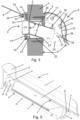
- the sub-assemblies 2, 3 are adapted to be connected together through the aperture 5 in the door 4 as is described in more detail below.
- the interior sub-assembly 2 is adapted to be secured to the door by a plurality of screws 6 that are located above and below the aperture 5.
- First and second flaps 7 and 8 are also provided as part of each sub-assembly 2 and 3 respectively and are pivotally mounted so that in use they cover the aperture 5 on the interior and exterior sides of the door 4.
- a sleeve 9 is provided that defines an inlet 10 and an outlet 11 on exterior and interior sides respectively of the letter-plate 1.
- the sleeve 9 lines the interior of the aperture 5 and is arranged at an oblique angle a to a vertical plane of the door 4.
- the sleeve 9 extends at an angle a of between 70° and 75° inclusive to the vertical plane of the door 4 and slopes downwards from the exterior side to the interior side of the letter-plate 1.
- the upper part of the sleeve 9 projects outwards from the interior side of the door 4 as an additional security measure. This projection of the sleeve 9 is covered by and accommodated within the interior flap 7 when the latter is closed.
- the sleeve 9, which primarily forms part of the interior sub-assembly 2 aligns with a short exterior portion 12 that is defined by an insert 13 forming part of the exterior sub-assembly 3.
- the reason for the oblique angle of the sleeve 9 is to make it difficult for fishing through it to occur and to be successful.
- Fishing implements or an arm inserted into the sleeve 9 are directed downwards and therefore away from adjacent door latches and locks.
- the height H of the sleeve 9 perpendicular to its size is restricted, preferably to between 30mm and 35mm inclusive. In most cases it is expected that the height H of the sleeve 9 will be 32 mm.
- the sleeve 9 is therefore of sufficient size to allow gauge mail to pass through it but sufficiently restricted in height to make passage of the arm of most people through it impossible and fishing using implements more difficult. Fishing using implements and tools is also made more difficult by restricting the pivotal movement of the flap 7 of the interior sub-assembly 2, as is described in more detail below,
- the exterior sub-assembly 3 is the simpler in construction than the interior sub-assembly 2 and is not designed to be independently secured to the door 4 but only to the interior sub-assembly 2. It is therefore connected to the interior sub-assembly 2 after the latter has been secured to the door 4. It comprises a frame 14 that is adapted to fit snugly around the periphery of the aperture 5 on the exterior side of the door 4.
- the insert 13 locates within the frame 5 and pairs of bolts 15 extend from the frame 14 through the insert 13 at respective sides thereof and to enable the sub-assembly 3 to be bolted to the interior sub-assembly 2 through the aperture 5 around the exterior of the sleeve 9.
- the bolts 15 pass through holes in a second frame 16 forming part of the interior sub-assembly 2 before being secured to the latter by nuts 17 or, in a modified arrangement, by screws that locate in threaded tubes used in place of the bolts 15.
- the exterior sub-assembly 3 is also secured to the interior sub-assembly 2 by two types of resilient, projecting fasteners 18 and 19 that are adapted to snap-fit to complementarily-shaped portions 20 and 21 respectively of the main part of the sleeve 9.
- the fasteners 18, 19 project from the insert 13 and their snap-fitment to the sleeve 9 aligns the apertures defined by the sleeve 9 and the portion 12 of the insert 13 to ensure that an unimpeded chute is formed through the door 4.
- the fasteners 18 comprise two pairs of projecting, resilient fingers that have nodules at their ends which engage within holes 20 defined in the sides of the sleeve 9 that are of a complementary shape in which the nodules will fit.
- the fasteners 19 comprise resilient hooks that are spaced along the lower part of the insert 3 below the sleeve portion 12 and snap-fit behind an upstanding flange 21 formed at the end of a tray 22 that is integrally formed with and, in use, projects horizontally below the sleeve 9.
- the tray 22 is designed to sit adjacent the lower surface of the aperture 5, typically over an intumescent strip (not shown).
- the tray 22 and the sleeve 9 are conjoined at the outlet 11, which flares outwardly and defines a lip 23 which locates around the interior, lower edge of the aperture 5.
- the lower screws 6 below the aperture 5 pass through the lip 23, thereby securing the sleeve 9 to the door, whereas the upper screws 6 above the aperture 5 pass through the frame 16, thereby also securing this firmly to the door 4.
- the flap 8 is pivotally mounted to the upper edge of the frame 14 and when closed it covers both the aperture 5 and the whole of the insert 13.
- the flap 8 is provided with a closure mechanism that biases it into a closed position so that it complies with relevant standards and does not rattle in the wind.
- the flap 8 is capable of withstanding attempts to pull it off the frame 14. This is because the frame 14 comprises a hooked upper edge 24 adjacent the pivotal mounting of the flap 8 , which edge 24 covers the pivots 25 and engages into a recess 26 provided along the entire length of the flap 8 when the flap 8 pivots open. This arrangement allows the flap 8 to withstand a 1kN pull test as specified in the aforesaid Technical Specification TS008:2015.
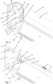
- the flap 7 of the interior sub-assembly 2 will now be described in more detail. It is pivotally mounted to the frame 16 by two spring-loaded pivot pins 27 attached to the frame 16 that locate in engagement holes 28 in the flap 7.
- the spring-loading 29 holds the pins 27 in place while facilitating assembly of the letter-plate 1 by providing flexibility in the order in which the various components can be assembled.
- the flap 7 is shaped so that when closed it covers the whole of the frame 16 and the projecting sleeve 9 and therefore the aperture 5.
- the flap 7 comprises a curved outer wall 30 with two side walls 31 that are secured to the outer wall 30 by grub screws 32 that screw into complementary engagement holes in the side walls 31.
- the screws 32 may have a thread-locking compound pre-applied to their threads so that once screwed tight they lock the side walls 31 to the flap 7.
- the flap 7 defines an interior space in which the frame 16 and the end of the sleeve 9 are accommodated when the flap 7 is closed.
- the flap 7 is also designed to direct mail posted through the letter-plate 1 downwards as it exits from the outlet 11 of the sleeve 9. It is therefore provided with an inner wall 33 that is preferably integrally formed with the outer wall 30.
- the inner wall 33 is located adjacent the lower free edge 34 of the flap 7 and extends upwards over the lower part of the interior surface of the outer wall 30. This prevents mail from being caught within the interior recess defined by the wall 30.
- the inner wall 33 also provides strength and rigidity to the flap 7.
- the pivotal movement of the flap 7 is also restricted. This is accomplished by stays, and preferably by at least one and more preferably by two pairs of stays 34, 35. Each pair of stays, 34, 35 is connected between the flap 7 and one of two projecting extensions 36 respectively formed at the two sides of the sleeve 9. The fingers 18 are also accommodated within this extension 36.
- the stay 34 is pivotally mounted to the extension 36 and defines a slot 37 along which a projecting portion 38 of the second stay 35 slides when the flap 7 is opened and closed.
- the projecting portion 38 is preferably a pin that is carried by the side wall 31 of the flap 7 and retained within the slot 37 by a washer 39 and cap 40 that is secured to a free end of the pin 38 projecting through the slot 37.
- the pin 38 may be threaded or left smooth on its exterior. If threaded, it has thread-locking compound applied to it so that it does not disconnect from the flap 7 after securement thereto.
- Figs. 1 and 3 both show the maximum extent to which the flap 7 can open.
- the flap 7 cannot pivot sufficiently to clear the upper, projecting portion of the sleeve 9 so that the actual opening through which mail egresses from the letter-plate 1 directs the mail downwardly, the flap 7 and the side walls 31 providing a shield to the areas above and to the sides of the letter-plate 1. This severely restricts the freedom to conduct fishing attacks and makes it hard for fishers to access adjacent locks and much beyond the interior surface of the door 4.
- the stay 34 also has an enlarged shape below the slot 37 to provide a further shield at the sides of the flap 7 when it is open. When closed, the stays 34, 35 are covered by the flap 7.
- pivotal movement of the flap 7 relative to the sleeve 9 is restricted such that the maximum opening angle of the flap 7 is limited to an angle b that is equal to or less than 60° with respect to said vertical plane of the door 4.
- the angle b is between 45° and 60° inclusive.
- the letter- plate 1 is fitted to the door 4 by first inserting the sleeve 9 of the interior sub-assembly 2 into the aperture 5 from the interior side of the door. At this point or even before the previous set the flap 7 can be disconnected from the sub-assembly 2, if necessary, to provide better access to the various fixing mechanisms but in most cases it is not thought that this will be necessary.
- the stays 34 and 35 are connected together and to the flap 7 but are disconnected from the sleeve extension 36. After insertion of the sleeve 9 into the aperture 5, the frame 16 and the lip 23 of the sleeve are screwed to the door 4 to secure the sub-assembly in place.
- the exterior sub-assembly 3 is then positioned on the exterior side of the door 4 and the exterior portion 12 of the sleeve 9 inserted into the aperture 5 to align with the sleeve 9.
- the fingers 18 locate into the sleeve extensions 36 on each side of the sleeve 9 and the nodules at their ends snap-fit into the holes 20.
- the hooks 19 slip over and grip the flange 21.
- the two sub-assemblies 2, 3 are now connected and aligned. They are then more permanently connected by attaching the nuts 17 to the bolts 15, or alternatively screwing the screws into the threaded rods, and making them fast.
- the stay or stays 34 are then connected to the sleeve extension 36 by a screw or screws such that they can pivot when the flap 7 opens and closes. Finally, the flap 7, if previously removed, is pivotally attached to the frame 16 by inserting the pivot pins 27 into the engagement holes 28.
- the letter-plate 1 is now assembled and in position ready for use.
Landscapes
- Supports Or Holders For Household Use (AREA)
- Hinges (AREA)
- Specific Sealing Or Ventilating Devices For Doors And Windows (AREA)
Applications Claiming Priority (4)
| Application Number | Priority Date | Filing Date | Title |
|---|---|---|---|
| GB1712040.3A GB2565275B (en) | 2017-07-26 | 2017-07-26 | Improvements to letter-plates |
| EP23153799.4A EP4197400A1 (de) | 2017-07-26 | 2018-07-25 | Verbesserungen an brieftafeln |
| EP18746839.2A EP3657994B1 (de) | 2017-07-26 | 2018-07-25 | Verbesserungen an briefeinwürfen |
| PCT/EP2018/025203 WO2019020217A1 (en) | 2017-07-26 | 2018-07-25 | IMPROVEMENTS IN LETTER BOX ENTRANCES |
Related Parent Applications (2)
| Application Number | Title | Priority Date | Filing Date |
|---|---|---|---|
| EP23153799.4A Division EP4197400A1 (de) | 2017-07-26 | 2018-07-25 | Verbesserungen an brieftafeln |
| EP18746839.2A Division EP3657994B1 (de) | 2017-07-26 | 2018-07-25 | Verbesserungen an briefeinwürfen |
Publications (2)
| Publication Number | Publication Date |
|---|---|
| EP4434409A2 true EP4434409A2 (de) | 2024-09-25 |
| EP4434409A3 EP4434409A3 (de) | 2024-11-27 |
Family
ID=59771709
Family Applications (3)
| Application Number | Title | Priority Date | Filing Date |
|---|---|---|---|
| EP18746839.2A Active EP3657994B1 (de) | 2017-07-26 | 2018-07-25 | Verbesserungen an briefeinwürfen |
| EP24185509.7A Pending EP4434409A3 (de) | 2017-07-26 | 2018-07-25 | Verbesserungen an brieftafeln |
| EP23153799.4A Pending EP4197400A1 (de) | 2017-07-26 | 2018-07-25 | Verbesserungen an brieftafeln |
Family Applications Before (1)
| Application Number | Title | Priority Date | Filing Date |
|---|---|---|---|
| EP18746839.2A Active EP3657994B1 (de) | 2017-07-26 | 2018-07-25 | Verbesserungen an briefeinwürfen |
Family Applications After (1)
| Application Number | Title | Priority Date | Filing Date |
|---|---|---|---|
| EP23153799.4A Pending EP4197400A1 (de) | 2017-07-26 | 2018-07-25 | Verbesserungen an brieftafeln |
Country Status (3)
| Country | Link |
|---|---|
| EP (3) | EP3657994B1 (de) |
| GB (2) | GB2565275B (de) |
| WO (1) | WO2019020217A1 (de) |
Families Citing this family (3)
| Publication number | Priority date | Publication date | Assignee | Title |
|---|---|---|---|---|
| GB2634086B (en) * | 2023-09-29 | 2026-01-28 | Assa Abloy Ltd | Letterplate with flap restrictor |
| GB2639517A (en) * | 2023-09-29 | 2025-10-01 | Assa Abloy Ltd | Letterplate with side plate assembly |
| GB2637758A (en) * | 2024-02-02 | 2025-08-06 | Rutland Trading Co Ltd | A letterplate assembly |
Family Cites Families (11)
| Publication number | Priority date | Publication date | Assignee | Title |
|---|---|---|---|---|
| US63141A (en) * | 1867-03-26 | Joseph m | ||
| GB958767A (en) * | 1963-04-09 | 1964-05-27 | Holden Co B Ham Ltd E | Letter plates |
| GB1034972A (en) * | 1964-07-15 | 1966-07-06 | W W Ball & Sons Ltd | A new or improved letter box |
| SE345195B (de) * | 1968-04-10 | 1972-05-23 | Hasselberg S | |
| FI121327B (fi) * | 2005-06-23 | 2010-10-15 | Abloy Oy | Postiluukku |
| FI121729B (fi) * | 2005-06-23 | 2011-03-31 | Abloy Oy | Postiluukku |
| EP2312975B1 (de) * | 2008-07-16 | 2012-08-15 | The Letterbox Guvnor Limited | Verriegelungsmittelvorrichtung für einen briefkasten |
| CN201664179U (zh) * | 2009-09-14 | 2010-12-08 | 江门达望五金装饰制品有限公司 | 一种信箱口 |
| DE202012003708U1 (de) * | 2012-04-13 | 2012-06-27 | S. Siedle & Söhne Telefon- und Telegrafenwerke OHG | Einwurfkasten |
| GB2521449B (en) * | 2013-12-20 | 2017-05-03 | Trojan Hardware & Design Ltd | Improvements in or relating to letter plate arrangements |
| GB2538045B (en) * | 2015-03-17 | 2020-06-10 | Uap Ltd | Improvements to letter-plates |
-
2017
- 2017-07-26 GB GB1712040.3A patent/GB2565275B/en active Active
-
2018
- 2018-07-25 GB GB2002309.9A patent/GB2579315B/en active Active
- 2018-07-25 EP EP18746839.2A patent/EP3657994B1/de active Active
- 2018-07-25 EP EP24185509.7A patent/EP4434409A3/de active Pending
- 2018-07-25 WO PCT/EP2018/025203 patent/WO2019020217A1/en not_active Ceased
- 2018-07-25 EP EP23153799.4A patent/EP4197400A1/de active Pending
Also Published As
| Publication number | Publication date |
|---|---|
| EP4197400A8 (de) | 2024-06-19 |
| GB202002309D0 (en) | 2020-04-01 |
| GB2565275A (en) | 2019-02-13 |
| GB2565275B (en) | 2020-08-19 |
| GB2579315B (en) | 2022-02-16 |
| EP4197400A1 (de) | 2023-06-21 |
| GB2579315A (en) | 2020-06-17 |
| EP3657994C0 (de) | 2023-06-07 |
| GB201712040D0 (en) | 2017-09-06 |
| EP3657994A1 (de) | 2020-06-03 |
| WO2019020217A1 (en) | 2019-01-31 |
| EP4434409A3 (de) | 2024-11-27 |
| EP3657994B1 (de) | 2023-06-07 |
Similar Documents
| Publication | Publication Date | Title |
|---|---|---|
| EP3657994B1 (de) | Verbesserungen an briefeinwürfen | |
| US8246124B2 (en) | Delivery storage locker | |
| US4502609A (en) | Sliding and pivoted closure for a lock box | |
| US8220296B2 (en) | Locking assembly hasp | |
| US4113291A (en) | Security locking system | |
| US9140033B2 (en) | FER locking system for sliding windows | |
| US9200481B2 (en) | Low profile security system for canine entry and exit | |
| US4394805A (en) | Escapable-window-security-guard system | |
| US9444179B1 (en) | Secure dual mount cover for outdoor electrical devices | |
| US8006527B2 (en) | Tamper inhibiting device for use with a lock | |
| CA2131511C (en) | Door security system | |
| US12264519B2 (en) | Tamper resistant hasp | |
| US4004833A (en) | Door lock device | |
| GB2576184A (en) | Security letter plate | |
| US20170335599A1 (en) | Guard for a latch to prevent opening | |
| US10738516B1 (en) | Window lock with adjustable reinforcement members | |
| US9932755B2 (en) | Door security device | |
| US11371273B2 (en) | Guard for a latch to prevent opening | |
| US20250059822A1 (en) | Door guard | |
| GB2546327A (en) | Security cowl and fixing | |
| GB2584544A (en) | Improvements to letter-plates | |
| GB2625833A (en) | Reversible gate locking mechanism | |
| US7232163B2 (en) | Sliding door lock | |
| US3933383A (en) | Latch | |
| GB2550166A (en) | Improvements to letter-plates |
Legal Events
| Date | Code | Title | Description |
|---|---|---|---|
| PUAI | Public reference made under article 153(3) epc to a published international application that has entered the european phase |
Free format text: ORIGINAL CODE: 0009012 |
|
| STAA | Information on the status of an ep patent application or granted ep patent |
Free format text: STATUS: THE APPLICATION HAS BEEN PUBLISHED |
|
| AC | Divisional application: reference to earlier application |
Ref document number: 3657994 Country of ref document: EP Kind code of ref document: P Ref document number: 4197400 Country of ref document: EP Kind code of ref document: P |
|
| AK | Designated contracting states |
Kind code of ref document: A2 Designated state(s): AL AT BE BG CH CY CZ DE DK EE ES FI FR GB GR HR HU IE IS IT LI LT LU LV MC MK MT NL NO PL PT RO RS SE SI SK SM TR |
|
| PUAL | Search report despatched |
Free format text: ORIGINAL CODE: 0009013 |
|
| AK | Designated contracting states |
Kind code of ref document: A3 Designated state(s): AL AT BE BG CH CY CZ DE DK EE ES FI FR GB GR HR HU IE IS IT LI LT LU LV MC MK MT NL NO PL PT RO RS SE SI SK SM TR |
|
| RIC1 | Information provided on ipc code assigned before grant |
Ipc: A47G 29/126 20060101AFI20241018BHEP |
|
| STAA | Information on the status of an ep patent application or granted ep patent |
Free format text: STATUS: REQUEST FOR EXAMINATION WAS MADE |
|
| 17P | Request for examination filed |
Effective date: 20250430 |