EP2312975B1 - Verriegelungsmittelvorrichtung für einen briefkasten - Google Patents
Verriegelungsmittelvorrichtung für einen briefkasten Download PDFInfo
- Publication number
- EP2312975B1 EP2312975B1 EP09784628A EP09784628A EP2312975B1 EP 2312975 B1 EP2312975 B1 EP 2312975B1 EP 09784628 A EP09784628 A EP 09784628A EP 09784628 A EP09784628 A EP 09784628A EP 2312975 B1 EP2312975 B1 EP 2312975B1
- Authority
- EP
- European Patent Office
- Prior art keywords
- letterbox
- stop member
- flap
- assembly
- support member
- Prior art date
- Legal status (The legal status is an assumption and is not a legal conclusion. Google has not performed a legal analysis and makes no representation as to the accuracy of the status listed.)
- Not-in-force
Links
- 230000000452 restraining effect Effects 0.000 claims abstract description 16
- 230000000712 assembly Effects 0.000 description 3
- 238000000429 assembly Methods 0.000 description 3
- 238000000034 method Methods 0.000 description 2
- 230000001419 dependent effect Effects 0.000 description 1
- 230000001627 detrimental effect Effects 0.000 description 1
- 238000002347 injection Methods 0.000 description 1
- 239000007924 injection Substances 0.000 description 1
- 238000009434 installation Methods 0.000 description 1
- 239000007788 liquid Substances 0.000 description 1
- 239000008188 pellet Substances 0.000 description 1
- 230000001681 protective effect Effects 0.000 description 1
- 239000000243 solution Substances 0.000 description 1
Images


Classifications
-
- A—HUMAN NECESSITIES
- A47—FURNITURE; DOMESTIC ARTICLES OR APPLIANCES; COFFEE MILLS; SPICE MILLS; SUCTION CLEANERS IN GENERAL
- A47G—HOUSEHOLD OR TABLE EQUIPMENT
- A47G29/00—Supports, holders, or containers for household use, not provided for in groups A47G1/00-A47G27/00 or A47G33/00
- A47G29/12—Mail or newspaper receptacles, e.g. letter-boxes; Openings in doors or the like for delivering mail or newspapers
- A47G29/122—Parts, details, or accessories, e.g. signalling devices, lamps, devices for leaving messages
- A47G29/124—Appliances to prevent unauthorised removal of contents
- A47G29/1245—Letter flap blocking devices
Definitions
- This invention relates to letterbox security and more particularly, but not exclusively, to letterboxes and letterbox assemblies that are suitable for installation in an external door or wall structure of domestic or industrial properties with security locking means which give protection against letterbox crime.
- Letterboxes are an essential item used by domestic households as well as businesses, providing unattended access for the delivery of items sent through the postal services.
- letterboxes are detrimental to the basic security of a home or business, for example, it is already known that arsonists start fires in homes and businesses by pouring in flammable liquids through letterboxes, it is also known that burglars and vandals peer through letterboxes in order to determine whether anyone is at home, prior to breaking into the premises.
- a letterbox In the light of the above problems, it is desirable for a letterbox to be only opened at certain times and to be closed at such other times for example - such as night time or when the occupants are on holiday and they have made arrangements for the mail to be held for collection at the local Post Office on their return from holiday.
- GB2208528A describes a protective device for a letter box according to the preambule of claim 1. It is an object of the present invention to address at least some of the disadvantages of prior art solutions by providing a letterbox assembly security device that may be manufactured as an integral part of a letterbox assembly and/or provide a simple stand alone device which may be easily installed for use with existing letterboxes which offer protection when operable to make it impossible to open the internal letter plate flap from the outside.
- a restraining device suitable for vertical mounting at right angle to the internal letter flap plate of conventional letterbox assemblies.
- an integrated letterbox locking means device suitable for use within a letterbox assembly and comprising restraining devices positioned at either right angle adjacent sides to the internal letter flap plate of a letterbox assembly.
- a restraining device for the flap of a letterbox comprising:
- the head member consists of a finger screw fastener. This enables the user to adjust and reposition the stop member by simply un-tightening and re-tightening the head member.
- the support member further includes a base member provided with at least one, preferably two fixing apertures such that, in use, the lock is securable adjacent the letterbox assembly or letterbox by way of fixing means passing through said fixing aperture(s).
- the device of the present invention is secured adjacent the letterbox flap, namely, above the letterbox flap and the stop member extends downwardly therefrom such that the position of the stop member relative to the letterbox flap is adjustable such that, in use, at least a portion of the stop member can restrict the degree by which the letterbox flap can open.
- the stop member is pivotably mounted on the support member and is releasably lockable at an angular position relative to the letterbox flap such that by adjusting the angle of the stop member relative to the letterbox flap can restrict the degree by which the letterbox flap can open.
- the length of the stop member is telescopically adjustable such that by adjusting the length of the stop member can restrict the degree by which the letterbox flap can open.
- the device is secured adjacent the letterbox, that is, at a side thereof, it is to be appreciated that the device can be secured at an appropriate position above the letterbox flap, that is, to control the degree by which the letterbox flap can open.
- the stop member may pivotally move relative to the letterbox flap to control the degree by which the letterbox flap may open. For example, if the stop member is locked parallel to the letterbox flap, the letterbox flap will be locked. If the stop member is then pivoted in an upwardly direction by, say 45 degrees and subsequently locked, then the letterbox will be able to partially open, and if the stop member is moved a further 45 degrees so that it extends at 90 degrees to the letterbox, the letterbox flap will be able to open fully i.e. the letterbox will be able to pivot 90 degrees from its closed position such that the opening it covers is fully open.
- a letterbox assembly comprising:
- the assembly includes two support members which are located at opposite sides of the letterbox flap, and each support member supports a separate stop member.
- the assembly includes two support members, which are located at opposite sides of the letterbox flap and which support a single stop member extending there between.
- the stop member comprises two head members which both include a threaded shaft extending from one end thereof and an elongate restraint with a threaded bore at either end thereof, such that, in use, the position of the elongate restraint between the two support members is fixable by way of the clamping action between each head member and its associated end of the elongate restraint on their associated support member.
- each head member consists of a finger screw fastener.
- the stop member comprises two head members which both include a threaded bore at one end thereof and an elongate restraint with a threaded shaft extending from either end thereof such that, in use, the position of the elongate member between the two support members is fixable by way of the clamping action between each head member and its associated end of the elongate restraint on their associated support member.
- the at least one support member is located above the letterbox flap and the stop member extends downwardly therefrom such that the position of the stop member relative to the letterbox flap is adjustable such that, in use, at least a portion of the stop member can restrict the degree by which the letterbox flap can open.
- the stop member is pivotably mounted on the support member and is releasably lockable at an angular position relative to the letterbox flap such that by adjusting the angle of the stop member relative to the letterbox flap can restrict the degree by which the letterbox flap can open.
- the length of the stop member is telescopically adjustable such that by adjusting the length of the stop member can restrict the degree by which the letterbox flap can open.
- the at least one support member is located to the side of the letterbox flap, it is to be appreciated that the support member and its associated stop member can be secured at an appropriate position above the letterbox flap, that is, to control the degree by which the letterbox flap can open.
- the stop member may pivotally move relative to the letterbox flap to control the degree by which the letterbox flap may open. For example, if the stop member is locked parallel to the letterbox flap, the letterbox flap will be locked. If the stop member is then pivoted in an upwardly direction by, say 45 degrees and subsequently locked, then the letterbox will be able to partially open, and if the stop member is moved a further 45 degrees so that it extends at 90 degrees to the letterbox, the letterbox flap will be able to open fully i.e. the letterbox will be able to pivot 90 degrees from its closed position such that the opening it covers is fully open.
- a door including the device or assembly of any one of the preceding claims.
- FIG. 1 illustrates an example of a restraining device 10 according to the present invention.
- the restraining device 10 comprises a support member 1 including a base member with two vertical fixing apertures 2, which facilitate fixing of the device 10 to the inside of a door, that is, by the use of suitable fixing means such as screws, nails etc.
- the base member of the support member 1 is further provided with a near 180 degree locking means positioning arcuate slot 3.
- the slot is arcuate in shape.
- the slot 3 facilitates a finger screw fastener 4 as well as letterbox flap screw threaded positioning restraint 5.
- the stop member that includes the finger screw fastener 4 and restraint 5 is releasably fixable and positionable at any point along the length of the slot 3 by the clamping action of the finger screw fastener 4 and restraint 5.
- the finger screw fastener 4 has a threaded shaft which, in use, is received by a threaded bore extending into the restraint 5.
- the screw fastener 4 may instead be provided with a threaded bore with the restraint 5 being provided with a threaded shaft extending from one side thereof and suitably sized to be received by said threaded bore.
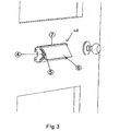
- Figure 3 illustrates an example of the restraining device 10 according to the present invention fitted to the inside of a door and positioned and fixed adjacent to the side of a typically installed letterbox assembly.
- the stand alone lock can be secured at a position above the installed letterbox assembly and/or letterbox flap.
- a letterbox assembly 20 includes a letterbox flap 6 which is pivotally connected to the frame of the letterbox assembly 7 by means of pivot pins (not shown). As illustrated, the letterbox flap 6 is shown in the partially open position and cannot open any further due to the letterbox flap positioning restraint 5 when finger screw fastener 4 is fully tightened. Put another way, due to the location of the stop member, which comprises the restraint 5 and fastener 4, within the slot 3, the degree to which the letterbox flap can open is limited.
- the letterbox flap 6 can be locked in any locking position from fully closed to fully open depending on where the positioning restraint 5 and finger screw fastener 4 is positioned within the body positioning slot 3 thus governing how much open or closed the occupant would like letterbox flap position to be fixed at.
- the degree by which the letterbox flap can open is dependent on where the stop member is fixably located along the length of the slot 3.
- the stop member comprising the restraint 5 and fastener 4 is located about half way down the slot 3 and, as such, the flap can open up to about 45 degrees.
- the fastener 4 of the stop member was un-tightened, and the stop member was relocated to the bottom of the slot 3 furthest away from the top end of the letterbox flap, which is attached to the assembly by way of the pivot pins, and then re-tightened, then the letterbox flap would not be able to open at all.
- the restraining device 10 as depicted in Figures 1 and 3 may be used at either side of the letterbox assembly in a left or right hand position by rotating the complete letterbox locking means device 10 by 180 degrees. It is also to be appreciated that it is also possible to include a separate restraining device 10 adjacent both sides of the letterbox flap for added security.
- Figure 4 illustrates a further example of a restraining device 100 according to the present invention comprising an integrated body section 8, which is a complete injection moulded part to be installed as part of a complete letterbox assembly.
- the letterbox locking means device 100 is provided with two stop members 11, each associated with a separate stop member each comprising a finger screw fastener 4 and letterbox flap screw threaded positioning restraint 5, at either side of the letterbox flap 6.
- Each stop member 11 is provided with an arcuate shaped slot 3 which define the path along which the stop member 11 can move.
- the manner in which the stop member works and engages with the support member is the same as the stand alone device 10 of Figures 1 and 3 .
- the supports 11 may support a single stop member suspended and held between the two support members.
- the stop member could comprise a single elongate member with a separate finger screw fastener at either end thereof.
- the support member(s) can be located at a position above the installed letterbox assembly and/or letterbox flap.
Landscapes
- Hinges (AREA)
Claims (15)
- Verriegelungsvorrichtung (10) für die Klappe eines Briefkastens, umfassend:ein Tragelement (1), das im Gebrauch neben einer Briefkastenanordnung oder einem Briefkasten gesichert werden kann; undeinem Anschlagelement, das von dem Tragelement (1) getragen ist und sich von dem Tragelement erstreckt, wobei die Position des Anschlagelements im Verhältnis zur Briefkastenklappe mittels eines vom Tragelement (1) vorgesehenen bogenförmigen Schlitzes (3) verstellbar ist und das Anschlagelement entlang des bogenförmigen Schlitzes (3) bewegt und lösbar an einem beliebigen Punkt entlang des bogenförmigen Schlitzes (3) befestigt werden kann, so dass im Gebrauch zumindest ein Bereich des Anschlagelements den Grad beschränken kann, um den sich die Briefkastenklappe öffnen kann, und dadurch gekennzeichnet, dass das Anschlagelement folgendes umfasst:entweder ein Kopfelement (4), das einen Schaft mit Gewinde einschließt, der sich von einem Ende desselben erstreckt, undeine längliche Rückhalteeinrichtung (5), die eine Bohrung mit Gewinde beinhaltet, die den Schaft mit Gewinde des Knopfelements (4) so aufnehmen kann, dass im Gebrauch die Position des Anschlagelements auf dem Tragelement (1) mittels des Klemmvorgangs des Kopfelements und der länglichen Rückhalteeinrichtung fixiert werden kann; odereine längliche Rückhalteeinrichtung (5), die einen Schaft mit Gewinde einschließt, der sich von einem Ende derselben erstreckt, undein Kopfielement (4), das eine Bohrung mit Gewinde einschließt, die den Schaft mit Gewinde der länglichen Rückhalteeinrichtung aufnehmen kann, so dass im Gebrauch die Position des Anschlagelements auf dem Tragelement mittels des Klemmvorgangs des Kopfelements und der länglichen Rückhalteeinrichtung fixiert werden kann.
- Vorrichtung nach Anspruch 1, wobei das Kopfelement (4) aus einem Fingerschraubenverbindungselement besteht:
- Vorrichtung nach irgendeinem der vorhergehenden Ansprüche, wobei das Tragelement (1) weiterhin ein Basiselement einschließt, das mit zumindest einer, vorzugsweise zwei Fixierungsöffnungen (2) versehen ist, so dass im Gebrauch die Vorrichtung neben der Briefkastenanordnung oder dem Briefkasten mittels einer Fixierungseinrichtung gesichert werden kann, die durch die Fixierungsöffnung(en) hindurchgeht.
- Vorrichtung nach Anspruch 1 oder 3, wobei im Gebrauch die Vorrichtung (10) über der Briefkastenklappe gesichert ist und das Anschlagelement von dieser so nach unten verläuft, dass die Position des Anschlagelements im Verhältnis zur Briefkastenklappe so verstellbar ist, dass im Gebrauch zumindest ein Bereich des Anschlagelements den Grad beschränken kann, um den sich die Briefkastenklappe öffnen kann.
- Vorrichtung nach Anspruch 4, wobei das Anschlagelement verschwenkbar auf dem Tragelement (1) angebracht ist und lösbar in einer Winkelposition im Verhältnis zur Briefkastenklappe verspannt werden kann, so dass durch Verstellen des Winkels des Anschlagelements im Verhältnis zur Briefkastenklappe den Winkel beschränken kann, um den sich die Briefkastenklappe öffnen kann.
- Vorrichtung nach Anspruch 4, wobei die Länge des Anschlagelements teleskopartig verstellt werden kann, so dass durch Verstellen der Länge des Anschlagelements den Grad beschränken kann, um den sich die Briefkastenklappe öffnen kann.
- Briefkastenanordnung (20), umfassend:eine Briefkastenklappe (6); unddie Verriegelungseinrichtung (10) nach irgendeinem der vorhergehenden Ansprüche.
- Anordnung nach Anspruch 7, wobei die Anordnung (20) zwei Tragelemente (1) einschließt, die sich auf gegenüberliegenden Seiten der Briefkastenklappe (6) befinden, und jedes Tragelement ein separates Anschlagelement trägt.
- Anordnung nach Anspruch 7, wobei die Anordnung (20) zwei Tragelemente (1) einschließt, die sich auf gegenüberliegenden Seiten der Briefkastenklappe (6) befinden und die ein einzelnes Anschlagelement tragen, das zwischen ihnen verläuft.
- Anordnung nach Anspruch 9, wobei das Anschlagselement zwei Kopfelemente (4) umfasst, die beide einen Schaft mit Gewinde, der sich von ihrem einen Ende erstreckt, und eine längliche Rückhalteeinrichtung (5) mit einer Bohrung mit Gewinde jeweils am Ende derselben einschießen, so dass im Gebrauch die Position der länglichen Rückhalteeinrichtung (5) zwischen den zwei Tragelementen (1) mittels des Klemmvorganges zwischen jedem Kopfelement und seinem zugeordneten Ende der länglichen Rückhalteeinrichtung (5) auf ihren zugeordneten Tragelement (1) befestigt werden kann, und wobei gegebenenfalls und vorzugsweise jedes Kopfelement aus einem Fingerschraubenverbindungselement besteht.
- Anordnung nach Anspruch 9, wobei das Anschlagelement (10) zwei Kopfelemente (4) umfasst, die beide eine Bohrung mit Gewinde an ihrem einen Ende und eine längliche Rückhalteeinrichtung (5) mit einem Schaft mit Gewinde, der sich jeweils von Ende derselben erstreckt, einschließen, so dass im Gebrauch die Position der länglichen Rückhalteeinrichtung (5) zwischen den zwei Tragelementen (1) mittels des Klemmvorgangs zwischen jedem Kopfelement und seinem zugeordneten Ende der länglichen Rückhalteeinrichtung (5) auf ihrem zugeordneten Tragelement (1) fixiert werden kann.
- Anordnung nach Anspruch 7, wobei sich das zumindest eine Anschlagelement über der Briefkastenklappe befindet und sich das Anschlagelement von dieser nach unten erstreckt, so dass die Position des Anschlagelements im Verhältnis zur Briefkastenklappe verstellbar ist, so dass im Gebrauch zumindest ein Bereich des Anschlagelements den Grad beschränken kann, um den sich die Briefkastenklappe öffnen kann.
- Anordnung nach Anspruch 12, wobei das Anschlagelement verschwenkbar auf dem Tragelement angebracht ist und lösbar in einer Winkelposition im Verhältnis zur Briefkastenklappe verspannt werden kann, so dass durch Verstellen des Winkels des Anschlagelements im Verhältnis zur Briefkastenklappe den Winkel beschränken kann, um den sich die Briefkastenklappe öffnen kann.
- Anordnung nach Anspruch 12, wobei die Länge des Anschlagelements teleskopartig verstellt werden kann, so dass durch Verstellen der Länge des Anschlagelements den Grad beschränken kann, um den sich die Briefkastenklappe öffnen kann.
- Tür einschließlich der Vorrichtung oder Anordnung nach irgendeinem der vorhergehende Ansprüche.
Applications Claiming Priority (3)
| Application Number | Priority Date | Filing Date | Title |
|---|---|---|---|
| GB0812965A GB0812965D0 (en) | 2008-07-16 | 2008-07-16 | Letter box assembly locking means device |
| GB0902688A GB0902688D0 (en) | 2009-02-18 | 2009-02-18 | Letter box assembly locking means device |
| PCT/GB2009/001576 WO2010007346A1 (en) | 2008-07-16 | 2009-06-23 | Letterbox assembly locking means device |
Publications (2)
| Publication Number | Publication Date |
|---|---|
| EP2312975A1 EP2312975A1 (de) | 2011-04-27 |
| EP2312975B1 true EP2312975B1 (de) | 2012-08-15 |
Family
ID=41138123
Family Applications (1)
| Application Number | Title | Priority Date | Filing Date |
|---|---|---|---|
| EP09784628A Not-in-force EP2312975B1 (de) | 2008-07-16 | 2009-06-23 | Verriegelungsmittelvorrichtung für einen briefkasten |
Country Status (2)
| Country | Link |
|---|---|
| EP (1) | EP2312975B1 (de) |
| WO (1) | WO2010007346A1 (de) |
Families Citing this family (4)
| Publication number | Priority date | Publication date | Assignee | Title |
|---|---|---|---|---|
| GB201002518D0 (en) * | 2010-02-15 | 2010-03-31 | Dominey Audrey | Staysafe locking letterbox |
| GB2546327B (en) * | 2016-01-18 | 2021-06-09 | Era Home Security Ltd | Security cowl and fixing |
| GB2550166B (en) * | 2016-05-11 | 2020-09-09 | Uap Ltd | Improvements to letter-plates |
| GB2565275B (en) * | 2017-07-26 | 2020-08-19 | Uap Ltd | Improvements to letter-plates |
Family Cites Families (4)
| Publication number | Priority date | Publication date | Assignee | Title |
|---|---|---|---|---|
| GB8626029D0 (en) * | 1986-10-29 | 1986-12-03 | Donaldson W K | Door furniture |
| GB8719210D0 (en) | 1987-08-13 | 1987-09-23 | Gregory D T E | Protection device for letter box |
| DE202005000570U1 (de) * | 2005-01-14 | 2005-04-14 | Pursche, Winfried | Briefkasten |
| DE202007014456U1 (de) * | 2007-10-16 | 2007-12-13 | Thomann, Hans-Jürgen, Dipl.-Ing. (FH) | Einwurfsperre für Briefkästen u.dgl. |
-
2009
- 2009-06-23 WO PCT/GB2009/001576 patent/WO2010007346A1/en not_active Ceased
- 2009-06-23 EP EP09784628A patent/EP2312975B1/de not_active Not-in-force
Also Published As
| Publication number | Publication date |
|---|---|
| EP2312975A1 (de) | 2011-04-27 |
| WO2010007346A1 (en) | 2010-01-21 |
Similar Documents
| Publication | Publication Date | Title |
|---|---|---|
| US20210079720A1 (en) | Secure In-Door Parcel Receiving Apparatus | |
| US10413106B1 (en) | Package door for a garage door | |
| US20190320835A1 (en) | Receptacle for receiving and securing packages and other items | |
| US11369223B2 (en) | Antitheft parcel delivery door system | |
| EP2312975B1 (de) | Verriegelungsmittelvorrichtung für einen briefkasten | |
| US6722561B1 (en) | Full service locked mailbox | |
| US5590608A (en) | Lockable lock box mounting assembly and method | |
| US11330926B1 (en) | Selectively securable container apparatus and method | |
| US9383060B2 (en) | Security wall rack and television mount combination | |
| US10709275B2 (en) | Theft-resistant wall mount mailbox | |
| US5617993A (en) | Locking mailbox | |
| US6120072A (en) | Doorstop | |
| US20070006794A1 (en) | Halyard system for a flag pole | |
| US6668487B2 (en) | System and method for applying an animal access door to an inclined surface | |
| US6520405B1 (en) | Mailbox lock | |
| US8485424B1 (en) | Reversible security mailbox | |
| US4905892A (en) | Damage-resistant mailbox | |
| US5031828A (en) | Damage-resistant mailbox | |
| US5597116A (en) | Top opening locking mailbox | |
| US10315497B2 (en) | Emergency vehicle door opening system | |
| US7178717B1 (en) | Mailbox security device | |
| US7896226B1 (en) | Secure mail box | |
| US6094950A (en) | Swing door lock for refrigerated cabinet | |
| US4901913A (en) | Damage-resistant mailbox | |
| EP1554955A1 (de) | Sicherheitsvorrichtung für einen Briefeinwurf |
Legal Events
| Date | Code | Title | Description |
|---|---|---|---|
| PUAI | Public reference made under article 153(3) epc to a published international application that has entered the european phase |
Free format text: ORIGINAL CODE: 0009012 |
|
| 17P | Request for examination filed |
Effective date: 20110214 |
|
| AK | Designated contracting states |
Kind code of ref document: A1 Designated state(s): AT BE BG CH CY CZ DE DK EE ES FI FR GB GR HR HU IE IS IT LI LT LU LV MC MK MT NL NO PL PT RO SE SI SK TR |
|
| AX | Request for extension of the european patent |
Extension state: AL BA RS |
|
| 17Q | First examination report despatched |
Effective date: 20110615 |
|
| DAX | Request for extension of the european patent (deleted) | ||
| GRAP | Despatch of communication of intention to grant a patent |
Free format text: ORIGINAL CODE: EPIDOSNIGR1 |
|
| GRAS | Grant fee paid |
Free format text: ORIGINAL CODE: EPIDOSNIGR3 |
|
| GRAA | (expected) grant |
Free format text: ORIGINAL CODE: 0009210 |
|
| AK | Designated contracting states |
Kind code of ref document: B1 Designated state(s): AT BE BG CH CY CZ DE DK EE ES FI FR GB GR HR HU IE IS IT LI LT LU LV MC MK MT NL NO PL PT RO SE SI SK TR |
|
| REG | Reference to a national code |
Ref country code: AT Ref legal event code: REF Ref document number: 570355 Country of ref document: AT Kind code of ref document: T Effective date: 20120815 Ref country code: GB Ref legal event code: FG4D Ref country code: CH Ref legal event code: EP |
|
| REG | Reference to a national code |
Ref country code: IE Ref legal event code: FG4D |
|
| REG | Reference to a national code |
Ref country code: DE Ref legal event code: R096 Ref document number: 602009009076 Country of ref document: DE Effective date: 20121011 |
|
| REG | Reference to a national code |
Ref country code: NL Ref legal event code: VDEP Effective date: 20120815 |
|
| REG | Reference to a national code |
Ref country code: AT Ref legal event code: MK05 Ref document number: 570355 Country of ref document: AT Kind code of ref document: T Effective date: 20120815 |
|
| PG25 | Lapsed in a contracting state [announced via postgrant information from national office to epo] |
Ref country code: HR Free format text: LAPSE BECAUSE OF FAILURE TO SUBMIT A TRANSLATION OF THE DESCRIPTION OR TO PAY THE FEE WITHIN THE PRESCRIBED TIME-LIMIT Effective date: 20120815 Ref country code: FI Free format text: LAPSE BECAUSE OF FAILURE TO SUBMIT A TRANSLATION OF THE DESCRIPTION OR TO PAY THE FEE WITHIN THE PRESCRIBED TIME-LIMIT Effective date: 20120815 Ref country code: NO Free format text: LAPSE BECAUSE OF FAILURE TO SUBMIT A TRANSLATION OF THE DESCRIPTION OR TO PAY THE FEE WITHIN THE PRESCRIBED TIME-LIMIT Effective date: 20121115 Ref country code: AT Free format text: LAPSE BECAUSE OF FAILURE TO SUBMIT A TRANSLATION OF THE DESCRIPTION OR TO PAY THE FEE WITHIN THE PRESCRIBED TIME-LIMIT Effective date: 20120815 Ref country code: LT Free format text: LAPSE BECAUSE OF FAILURE TO SUBMIT A TRANSLATION OF THE DESCRIPTION OR TO PAY THE FEE WITHIN THE PRESCRIBED TIME-LIMIT Effective date: 20120815 Ref country code: IS Free format text: LAPSE BECAUSE OF FAILURE TO SUBMIT A TRANSLATION OF THE DESCRIPTION OR TO PAY THE FEE WITHIN THE PRESCRIBED TIME-LIMIT Effective date: 20121215 |
|
| PG25 | Lapsed in a contracting state [announced via postgrant information from national office to epo] |
Ref country code: LV Free format text: LAPSE BECAUSE OF FAILURE TO SUBMIT A TRANSLATION OF THE DESCRIPTION OR TO PAY THE FEE WITHIN THE PRESCRIBED TIME-LIMIT Effective date: 20120815 Ref country code: SI Free format text: LAPSE BECAUSE OF FAILURE TO SUBMIT A TRANSLATION OF THE DESCRIPTION OR TO PAY THE FEE WITHIN THE PRESCRIBED TIME-LIMIT Effective date: 20120815 Ref country code: GR Free format text: LAPSE BECAUSE OF FAILURE TO SUBMIT A TRANSLATION OF THE DESCRIPTION OR TO PAY THE FEE WITHIN THE PRESCRIBED TIME-LIMIT Effective date: 20121116 Ref country code: SE Free format text: LAPSE BECAUSE OF FAILURE TO SUBMIT A TRANSLATION OF THE DESCRIPTION OR TO PAY THE FEE WITHIN THE PRESCRIBED TIME-LIMIT Effective date: 20120815 Ref country code: BE Free format text: LAPSE BECAUSE OF FAILURE TO SUBMIT A TRANSLATION OF THE DESCRIPTION OR TO PAY THE FEE WITHIN THE PRESCRIBED TIME-LIMIT Effective date: 20120815 Ref country code: PT Free format text: LAPSE BECAUSE OF FAILURE TO SUBMIT A TRANSLATION OF THE DESCRIPTION OR TO PAY THE FEE WITHIN THE PRESCRIBED TIME-LIMIT Effective date: 20121217 Ref country code: PL Free format text: LAPSE BECAUSE OF FAILURE TO SUBMIT A TRANSLATION OF THE DESCRIPTION OR TO PAY THE FEE WITHIN THE PRESCRIBED TIME-LIMIT Effective date: 20120815 |
|
| PG25 | Lapsed in a contracting state [announced via postgrant information from national office to epo] |
Ref country code: NL Free format text: LAPSE BECAUSE OF FAILURE TO SUBMIT A TRANSLATION OF THE DESCRIPTION OR TO PAY THE FEE WITHIN THE PRESCRIBED TIME-LIMIT Effective date: 20120815 |
|
| PG25 | Lapsed in a contracting state [announced via postgrant information from national office to epo] |
Ref country code: ES Free format text: LAPSE BECAUSE OF FAILURE TO SUBMIT A TRANSLATION OF THE DESCRIPTION OR TO PAY THE FEE WITHIN THE PRESCRIBED TIME-LIMIT Effective date: 20121126 Ref country code: DK Free format text: LAPSE BECAUSE OF FAILURE TO SUBMIT A TRANSLATION OF THE DESCRIPTION OR TO PAY THE FEE WITHIN THE PRESCRIBED TIME-LIMIT Effective date: 20120815 Ref country code: CZ Free format text: LAPSE BECAUSE OF FAILURE TO SUBMIT A TRANSLATION OF THE DESCRIPTION OR TO PAY THE FEE WITHIN THE PRESCRIBED TIME-LIMIT Effective date: 20120815 Ref country code: RO Free format text: LAPSE BECAUSE OF FAILURE TO SUBMIT A TRANSLATION OF THE DESCRIPTION OR TO PAY THE FEE WITHIN THE PRESCRIBED TIME-LIMIT Effective date: 20120815 Ref country code: EE Free format text: LAPSE BECAUSE OF FAILURE TO SUBMIT A TRANSLATION OF THE DESCRIPTION OR TO PAY THE FEE WITHIN THE PRESCRIBED TIME-LIMIT Effective date: 20120815 |
|
| PG25 | Lapsed in a contracting state [announced via postgrant information from national office to epo] |
Ref country code: SK Free format text: LAPSE BECAUSE OF FAILURE TO SUBMIT A TRANSLATION OF THE DESCRIPTION OR TO PAY THE FEE WITHIN THE PRESCRIBED TIME-LIMIT Effective date: 20120815 Ref country code: IT Free format text: LAPSE BECAUSE OF FAILURE TO SUBMIT A TRANSLATION OF THE DESCRIPTION OR TO PAY THE FEE WITHIN THE PRESCRIBED TIME-LIMIT Effective date: 20120815 |
|
| PLBE | No opposition filed within time limit |
Free format text: ORIGINAL CODE: 0009261 |
|
| STAA | Information on the status of an ep patent application or granted ep patent |
Free format text: STATUS: NO OPPOSITION FILED WITHIN TIME LIMIT |
|
| 26N | No opposition filed |
Effective date: 20130516 |
|
| PG25 | Lapsed in a contracting state [announced via postgrant information from national office to epo] |
Ref country code: BG Free format text: LAPSE BECAUSE OF FAILURE TO SUBMIT A TRANSLATION OF THE DESCRIPTION OR TO PAY THE FEE WITHIN THE PRESCRIBED TIME-LIMIT Effective date: 20121115 |
|
| REG | Reference to a national code |
Ref country code: DE Ref legal event code: R097 Ref document number: 602009009076 Country of ref document: DE Effective date: 20130516 |
|
| PG25 | Lapsed in a contracting state [announced via postgrant information from national office to epo] |
Ref country code: CY Free format text: LAPSE BECAUSE OF FAILURE TO SUBMIT A TRANSLATION OF THE DESCRIPTION OR TO PAY THE FEE WITHIN THE PRESCRIBED TIME-LIMIT Effective date: 20120815 |
|
| PG25 | Lapsed in a contracting state [announced via postgrant information from national office to epo] |
Ref country code: MC Free format text: LAPSE BECAUSE OF FAILURE TO SUBMIT A TRANSLATION OF THE DESCRIPTION OR TO PAY THE FEE WITHIN THE PRESCRIBED TIME-LIMIT Effective date: 20120815 |
|
| REG | Reference to a national code |
Ref country code: CH Ref legal event code: PL |
|
| REG | Reference to a national code |
Ref country code: DE Ref legal event code: R119 Ref document number: 602009009076 Country of ref document: DE Effective date: 20140101 |
|
| REG | Reference to a national code |
Ref country code: FR Ref legal event code: ST Effective date: 20140228 |
|
| PG25 | Lapsed in a contracting state [announced via postgrant information from national office to epo] |
Ref country code: LI Free format text: LAPSE BECAUSE OF NON-PAYMENT OF DUE FEES Effective date: 20130630 Ref country code: DE Free format text: LAPSE BECAUSE OF NON-PAYMENT OF DUE FEES Effective date: 20140101 Ref country code: CH Free format text: LAPSE BECAUSE OF NON-PAYMENT OF DUE FEES Effective date: 20130630 |
|
| PG25 | Lapsed in a contracting state [announced via postgrant information from national office to epo] |
Ref country code: FR Free format text: LAPSE BECAUSE OF NON-PAYMENT OF DUE FEES Effective date: 20130701 |
|
| PG25 | Lapsed in a contracting state [announced via postgrant information from national office to epo] |
Ref country code: MT Free format text: LAPSE BECAUSE OF FAILURE TO SUBMIT A TRANSLATION OF THE DESCRIPTION OR TO PAY THE FEE WITHIN THE PRESCRIBED TIME-LIMIT Effective date: 20120815 |
|
| PGFP | Annual fee paid to national office [announced via postgrant information from national office to epo] |
Ref country code: IE Payment date: 20150305 Year of fee payment: 7 |
|
| PG25 | Lapsed in a contracting state [announced via postgrant information from national office to epo] |
Ref country code: TR Free format text: LAPSE BECAUSE OF FAILURE TO SUBMIT A TRANSLATION OF THE DESCRIPTION OR TO PAY THE FEE WITHIN THE PRESCRIBED TIME-LIMIT Effective date: 20120815 |
|
| PG25 | Lapsed in a contracting state [announced via postgrant information from national office to epo] |
Ref country code: MK Free format text: LAPSE BECAUSE OF FAILURE TO SUBMIT A TRANSLATION OF THE DESCRIPTION OR TO PAY THE FEE WITHIN THE PRESCRIBED TIME-LIMIT Effective date: 20120815 Ref country code: HU Free format text: LAPSE BECAUSE OF FAILURE TO SUBMIT A TRANSLATION OF THE DESCRIPTION OR TO PAY THE FEE WITHIN THE PRESCRIBED TIME-LIMIT; INVALID AB INITIO Effective date: 20090623 Ref country code: LU Free format text: LAPSE BECAUSE OF NON-PAYMENT OF DUE FEES Effective date: 20130623 |
|
| PGFP | Annual fee paid to national office [announced via postgrant information from national office to epo] |
Ref country code: GB Payment date: 20150408 Year of fee payment: 7 |
|
| GBPC | Gb: european patent ceased through non-payment of renewal fee |
Effective date: 20160623 |
|
| REG | Reference to a national code |
Ref country code: IE Ref legal event code: MM4A |
|
| PG25 | Lapsed in a contracting state [announced via postgrant information from national office to epo] |
Ref country code: IE Free format text: LAPSE BECAUSE OF NON-PAYMENT OF DUE FEES Effective date: 20160623 Ref country code: GB Free format text: LAPSE BECAUSE OF NON-PAYMENT OF DUE FEES Effective date: 20160623 |