EP4434407A2 - Trägerelement für eine uhr, wie eine armbanduhr, oder ein schmuckstück - Google Patents
Trägerelement für eine uhr, wie eine armbanduhr, oder ein schmuckstück Download PDFInfo
- Publication number
- EP4434407A2 EP4434407A2 EP24187780.2A EP24187780A EP4434407A2 EP 4434407 A2 EP4434407 A2 EP 4434407A2 EP 24187780 A EP24187780 A EP 24187780A EP 4434407 A2 EP4434407 A2 EP 4434407A2
- Authority
- EP
- European Patent Office
- Prior art keywords
- support element
- internal cavity
- timepiece
- piece
- central portion
- Prior art date
- Legal status (The legal status is an assumption and is not a legal conclusion. Google has not performed a legal analysis and makes no representation as to the accuracy of the status listed.)
- Granted
Links
Images
Classifications
-
- A—HUMAN NECESSITIES
- A47—FURNITURE; DOMESTIC ARTICLES OR APPLIANCES; COFFEE MILLS; SPICE MILLS; SUCTION CLEANERS IN GENERAL
- A47F—SPECIAL FURNITURE, FITTINGS, OR ACCESSORIES FOR SHOPS, STOREHOUSES, BARS, RESTAURANTS OR THE LIKE; PAYING COUNTERS
- A47F7/00—Show stands, hangers, or shelves, adapted for particular articles or materials
- A47F7/02—Show stands, hangers, or shelves, adapted for particular articles or materials for jewellery, dentures, watches, eye-glasses, lenses, or the like
-
- A—HUMAN NECESSITIES
- A47—FURNITURE; DOMESTIC ARTICLES OR APPLIANCES; COFFEE MILLS; SPICE MILLS; SUCTION CLEANERS IN GENERAL
- A47F—SPECIAL FURNITURE, FITTINGS, OR ACCESSORIES FOR SHOPS, STOREHOUSES, BARS, RESTAURANTS OR THE LIKE; PAYING COUNTERS
- A47F7/00—Show stands, hangers, or shelves, adapted for particular articles or materials
- A47F7/02—Show stands, hangers, or shelves, adapted for particular articles or materials for jewellery, dentures, watches, eye-glasses, lenses, or the like
- A47F7/03—Show stands, hangers, or shelves, adapted for particular articles or materials for jewellery, dentures, watches, eye-glasses, lenses, or the like of box shape; Adaptations of boxes to display purposes
-
- A—HUMAN NECESSITIES
- A45—HAND OR TRAVELLING ARTICLES
- A45C—PURSES; LUGGAGE; HAND CARRIED BAGS
- A45C11/00—Receptacles for purposes not provided for in groups A45C1/00-A45C9/00
- A45C11/10—Watch cases or guards, with or without windows
-
- A—HUMAN NECESSITIES
- A45—HAND OR TRAVELLING ARTICLES
- A45C—PURSES; LUGGAGE; HAND CARRIED BAGS
- A45C11/00—Receptacles for purposes not provided for in groups A45C1/00-A45C9/00
- A45C11/16—Jewel boxes
-
- A—HUMAN NECESSITIES
- A47—FURNITURE; DOMESTIC ARTICLES OR APPLIANCES; COFFEE MILLS; SPICE MILLS; SUCTION CLEANERS IN GENERAL
- A47F—SPECIAL FURNITURE, FITTINGS, OR ACCESSORIES FOR SHOPS, STOREHOUSES, BARS, RESTAURANTS OR THE LIKE; PAYING COUNTERS
- A47F5/00—Show stands, hangers, or shelves characterised by their constructional features
-
- A—HUMAN NECESSITIES
- A47—FURNITURE; DOMESTIC ARTICLES OR APPLIANCES; COFFEE MILLS; SPICE MILLS; SUCTION CLEANERS IN GENERAL
- A47F—SPECIAL FURNITURE, FITTINGS, OR ACCESSORIES FOR SHOPS, STOREHOUSES, BARS, RESTAURANTS OR THE LIKE; PAYING COUNTERS
- A47F5/00—Show stands, hangers, or shelves characterised by their constructional features
- A47F5/10—Adjustable or foldable or dismountable display stands
-
- A—HUMAN NECESSITIES
- A47—FURNITURE; DOMESTIC ARTICLES OR APPLIANCES; COFFEE MILLS; SPICE MILLS; SUCTION CLEANERS IN GENERAL
- A47F—SPECIAL FURNITURE, FITTINGS, OR ACCESSORIES FOR SHOPS, STOREHOUSES, BARS, RESTAURANTS OR THE LIKE; PAYING COUNTERS
- A47F7/00—Show stands, hangers, or shelves, adapted for particular articles or materials
- A47F7/02—Show stands, hangers, or shelves, adapted for particular articles or materials for jewellery, dentures, watches, eye-glasses, lenses, or the like
- A47F7/022—Show stands, hangers, or shelves, adapted for particular articles or materials for jewellery, dentures, watches, eye-glasses, lenses, or the like for watches or for bracelets therefor
Definitions
- the field of the invention concerns devices for presenting and protecting objects, in particular timepieces or items of jewelry.
- the invention relates more particularly to a removable support element, for example for a wristwatch, intended to be integrated into a storage unit and/or a display stand.
- timepieces or jewelry items in storage devices, such as boxes or protective cases.
- Such storage organs can take different forms and generally allow to store and/or transport one or more watch parts. These storage organs are classically called display case, box, case, case, box, case, pouch, etc.
- the term storage organ will be used in the remainder of this application to designate indifferently a box, a case, a case, a display stand, a storage unit, a pouch, or any other container intended to receive and protect from shocks, scratches, or even scratches a timepiece or a piece of jewelry.
- the storage organs are generally of rigid design and can have a flexible, quilted or even velvety interior covering so as to form a case. protector thus avoiding any risk of damage to the object housed inside the storage unit.
- These storage members generally have at least one compartment configured to allow the positioning of a removable support element intended to receive the timepiece, such as a wristwatch, or the jewelry item.
- a removable support element intended to receive the timepiece, such as a wristwatch, or the jewelry item.
- These support elements perform a support function but also protect the internal elements of the timepiece, or the jewelry item, against scratches, scrapes and/or impacts.
- the support element may be, for example, a kind of removable cushion, also called a bobbin, or a flexible support having a C-shaped strip or blade adapted to receive a wristwatch or an item of jewelry.
- Some organizers may also have additional compartments sized to accommodate various accessories, such as bracelets, microfiber cleaning cloths, jewelry items, magnification devices, etc.
- the user is forced to choose between using a compact box that does not allow the transport of additional accessories, but has a reduced size, thus facilitating transport and accommodation in luggage, or using a large storage unit that is bulky and impractical to accommodate in luggage, in which he can transport at least one wristwatch, or one item of jewelry, as well as the accessories that he wishes to transport with him.
- the invention proposes a new support element for a timepiece, in particular a wristwatch, or a jewelry item that solves the drawbacks presented above.
- the invention relates to a support element for a timepiece, or a piece of jewelry, comprising a receiving surface configured to be at least partly in direct contact with said timepiece, or the piece of jewelry, said support element comprising a peripheral portion carrying said receiving surface, and a central portion constituted by a block of material, said support element being characterized in that it comprises an internal cavity forming a recess in the central portion; said internal cavity delimiting a volume configured to receive and hold in position an object inside said support element.
- the support element according to the invention allows, in addition to a support function, to be able to integrate and house an object inside the material of the support element.
- the modularity of such a support element is optimized by reducing the non-functional parts.
- the support element according to the invention makes it possible to exploit, enhance and use a "lost" volume, i.e. without any particular function, located in a central region of the support elements, of the reel type, existing in the state of the art.
- a "lost" volume i.e. without any particular function, located in a central region of the support elements, of the reel type, existing in the state of the art.
- Such a support element according to the invention exploiting this lost volume thus makes it possible to integrate without additional bulk an object useful for the customer.
- the central portion further comprises at least one removable portion arranged on the periphery of said internal cavity, said removable portion being configured to modify the shape and/or dimensions of said internal cavity when said removable portion is removed from the central portion.
- the shape of the internal cavity is in line with the object that one wishes to integrate into the support element.
- the internal cavity can have different shapes and in particular a circular, oval, ovoid, oblong, or even polygonal section, depending on the needs.
- the central portion comprises at least one region made of cellular material, elastomer or viscoelastic polymer, said internal cavity being located at said region made of cellular material, elastomer or viscoelastic polymer.
- the material of the internal cavity helps to promote the maintenance of the object.
- the central portion comprises at least one region made of polyurethane foam or polyethylene foam, said internal cavity being located at the level of said region made of polyurethane foam or polyethylene foam.
- the object is held in said internal cavity by elastic or viscoelastic response of the material following a deformation of the internal cavity.
- the central portion has a density of between 30 and 90 Shore A.
- the peripheral portion is made of cellular material, elastomer or viscoelastic polymer.
- the material of the peripheral portion provides a soft and deformable contact for positioning the timepiece.
- the peripheral portion and the central portion are monobloc.
- the manufacturing process is simplified.
- said internal cavity extends on either side of said central portion. Thus, the removal of the object inside the internal cavity is facilitated.
- said internal cavity delimits a volume configured to receive and hold in position a timepiece accessory or a piece of jewelry inside said support element.
- the watch accessory is a magnifying device.
- the user can carry a watchmaker's loupe easily without additional bulk.
- said internal cavity has a counterbore shape. This shape advantageously makes it possible to integrate a watchmaker's loupe and to form a positioning stop.
- said support element comprises a removal member configured to allow the removal of the object outside the internal cavity.
- the user has a means for easily removing the object from the internal cavity without risk of damage to the object or the internal cavity of the support element.
- the support element has a shape suitable for receiving a wristwatch at said receiving surface.
- the invention also relates to a storage member for a timepiece or a piece of jewelry, characterized in that it comprises an external casing comprising a movable portion, movable between a closed position and an open position, said open position of the movable element allowing access to an internal compartment provided inside the external casing; a support element according to the invention positioned removably in said internal compartment.
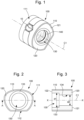
- FIG. 1 is a schematic perspective representation of a first exemplary embodiment of a support element 100 according to the invention.
- FIG 2 illustrates a side view of the first exemplary embodiment of the support element 100 illustrated in figure 1 .
- FIG 3 illustrates a sectional view of the first exemplary embodiment of the support element 100 illustrated in the figure 1 , according to the section plane AA illustrated in the figure 2 .
- the support element 100 has a general shape suitable for the positioning and mounting of a timepiece 10, such as a wristwatch and/or a piece of jewelry (not shown).
- the support element 100 may have, for example, a cylindrical, ovoid, ellipsoid, etc. shape, and may be composed of one or more convex surfaces formed by one or more radii of curvature.
- a cylindrical shape is understood to mean a shape having a ruled surface whose generatrices are parallel, that is to say a surface in space consisting of parallel straight lines.
- a cylindrical shape according to the invention is not necessarily related to a right cylinder which is a particular shape of a cylinder.
- the support element 100 is of the cushion or bobbin type, having a geometry and dimensions adapted to receive a timepiece and/or a piece of jewelry, and in particular a wristwatch.
- the support element 100 comprises a central portion 120 forming a block of material, as well as a peripheral portion 110 formed on the periphery of the central portion 120, said peripheral portion 110 being able to be removable or in one piece with the central portion 120.
- the support element 100 is a block of material comprising a central portion 120 and a peripheral portion 110.
- the peripheral portion 110 has a curved, essentially convex receiving surface 111, intended to be at least partly in direct contact with said timepiece 10, and more particularly with the internal diameter of the bracelet of a wristwatch, and possibly with the bottom of the case of the wristwatch, or of the jewelry item.
- the receiving surface 111 is composed of a plurality of convex surfaces having several radii of curvature.
- the peripheral portion 110 may also comprise, as illustrated in Figures 1 to 3 , a flat lower surface 112 sufficiently wide to facilitate maintenance, and to guarantee stable maintenance of the support element 100.
- the support element 100 further has two flanks 121, 122 forming the lateral faces of the support element 100.
- the peripheral portion 110, the central portion 120 and the flanks 121, 122 thus define the general volume of the support element 100.
- flanks 121, 122 of the support element 100 are shown to be substantially flat and parallel to each other so that the support element has a generally cylindrical shape; however, this representation is an exemplary embodiment and is not limiting of the invention. Indeed, the flanks 121, 122 of the support element 100 may have various shapes (for example curved, convex or concave) and be arranged in the same plane or not, symmetrically or not.
- the support element 100 also has an internal housing, or an internal cavity 130, forming a recess in the central part 120.
- the internal cavity 130 is preferably provided at the level of the central portion 120 of the support element 100.
- the internal cavity 130 is formed substantially in a central region of the central portion 120.
- the internal cavity 130 opens at one of the sides 121, 122 of the support element 100.
- the internal cavity 130 opens at the level of the two flanks 122, 122 of the support element 100, so that the internal cavity 130 passes through the central portion 120 of the support element 100 on either side.
- the internal cavity 130 extends along an axis X-X substantially parallel to a central axis C1 of the support element 100.
- the internal cavity 130 extends along an axis X-X coaxial with the central axis C1 of the support element 100.
- the internal cavity 130 is sized so as to allow the introduction of an accessory 140 inside the support element 100, as well as its maintenance inside this internal cavity 130.
- the internal cavity 130 has a shape that matches the type of accessory 140 that it is desired to integrate into the support element 100.
- the internal cavity 130 can have different shapes and in particular a section of circular, oval, ovoid, oblong, or even polygonal shape, depending on the needs.
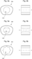
- FIG. 4a, 5a and 6a represent, in side view, alternative embodiments of the support element 100 illustrated in Figures 1 to 3 .
- FIG. 4b, 5b and 6b represent the sectional views of these variants of embodiment according to the same section plane AA illustrated in figure 2 .
- the support element 100a according to the invention comprises an internal cavity 130a of circular section, and of constant dimension.
- the support element 100b comprises an internal cavity 130b having a circular section whose diameter varies along the axis XX, such that the internal cavity 130b has a curved profile of concave shape in the direction of the axis XX.
- a profile of the internal cavity 130b makes it possible, for example, to guarantee the maintenance of a small accessory in the center of the support element 100 and/or of a larger accessory at the ends of the internal cavity 130b (i.e. close to the sides 121, 122).
- Such a profile also makes it possible to guarantee privileged retention of an accessory 140 at the central part 120 of the internal cavity 130 while facilitating the gripping of the accessory 140 by the user when he wishes to remove it from the internal cavity 130, in particular if the dimensions of the ends of the internal cavity 130 are greater than the dimensions of the ends of the accessory 140.
- the support element 100c comprises an internal cavity 130c of polygonal section, for example in the shape of a star.
- a shape makes it possible to provide a versatile housing for positioning various accessories of different shapes, such as for example an accessory of straight cylindrical, spherical, cubic, or even rectangular shape.
- the section of the internal cavity 130 can have variable shapes, as well as variable dimensions depending on the type of accessory 140 that one wishes to integrate into the internal cavity 130 of the support element 100.
- the internal cavity 130 has a cylindrical shape composed of two parts of constant sections and different dimensions so that the internal cavity 130 forms a counterbore.
- the internal cavity 130 has a first diameter d1 at one of its ends and a second diameter d2, less than d1, at its other end.
- the difference in bore diameter of the internal cavity 130 thus makes it possible to create an annular shoulder 133 inside the internal cavity 130 configured to form a positioning stop for the accessory 140.
- the dimensions of the internal cavity 130 are slightly smaller than the dimensions of the accessory 140 that it is desired to integrate inside the support element 100, so as to allow maintenance by friction and/or by elastic or viscoelastic response of the material following a deformation thereof during the introduction of the accessory 140 into the internal cavity 130.
- the accessory 140 is maintained in the internal cavity 130, for example, by friction of the accessory 140 against at least a portion of the wall 134 of the internal cavity 130.
- the wall 134 of the internal cavity 130 may be covered with a coating promoting interaction with the accessory 140, or may have surface irregularities, or protuberances, such as for example bosses, at the surface of the wall 134 of the internal cavity 130.
- the irregularities or protuberances are advantageously made from a material promoting friction or interaction with the accessory 140.
- the irregularities or protuberances may be made of a material different from the material used to make the central portion 120, and which advantageously has anti-slip properties so as to increase, if necessary, the maintenance of the accessory 140 inside the internal cavity 130, in particular during handling of the support element 100.
- the accessory 40 can also be held in place, in a complementary or independent manner with the example described in the preceding paragraphs, by applying pressure to the accessory 140 when the latter is in position in the internal cavity 130.
- the pressure is exerted on the accessory 140 by elastic or viscoelastic response of the surrounding material due to a slight deformation of the internal cavity 130 following the introduction of the accessory 140, in particular when the dimensions of the internal cavity 130 are slightly smaller than the dimensions of the accessory 140.
- the central portion 120 comprises at least one region made of a flexible material having elastic or viscoelastic properties, the internal cavity 130 being formed in this particular region of the central portion 120.
- a flexible material is a material that can be easily deformed manually, with a density between 30 and 90 Shore A.
- the soft material can be, for example, a cellular material, for example a polymer foam, an elastomer, a viscoelastic polymer.
- the soft material is, for example, polyurethane foam or polyethylene foam.
- the entire central portion 120 is made of a flexible material having elastic or viscoelastic properties.
- the material of the central portion 120 of the support element 100 and the material of the peripheral portion 110 are identical. However, the densities and hardnesses of these two portions may be different.
- the material of the peripheral portion 110 is different from the material of the central portion 120.
- the peripheral portion can thus be made of a more rigid material than the central portion and be covered for example with leather, fabric or synthetic material so as to protect the inner part of the timepiece 10 or the jewelry item from scratches and/or scuffs.
- the support element 100 is a single-piece element, that is to say that the central portion 120 and the peripheral portion 110 are in one piece.
- the peripheral portion 110 and the central portion 120 may be made from the same material (with different or equivalent properties) or from different materials.
- the support element can be produced by polymerization or by bonding of the two portions.
- the central portion 120 and the peripheral portion 110 are two separate parts, i.e. made separately.
- the central portion 120 and the peripheral portion 110 may have identical or different characteristics and be made from an identical or different material.
- the support element 100 may consist of a peripheral portion of flexible support type formed by a C-shaped strip or blade and a solid central portion made of flexible or foamy material as mentioned in the preceding examples and variant embodiments.
- the strip or blade can be made of spring steel or plastic, for example, and covered with a material such as leather, fabric or even synthetic material.
- the two portions can then be assembled and held together by gluing or even be removable from each other.
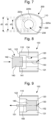
- FIG. 7 illustrates a second exemplary embodiment of a support element 200 according to the invention.
- This second exemplary embodiment is identical to the first exemplary embodiment as well as to the different embodiment variants mentioned with the exception of the characteristics which will be described later.
- the central portion 220 of the support element 200 is formed by the combination of different portions 220a, 220b, 220c arranged on the periphery of the internal cavity 130, extending concentrically, or not, along the axis X-X of the internal cavity 230.
- removable portions 220b, 220c are shown. These removable portions 220b, 220c make it possible to modulate the shape and/or dimensions of the internal cavity 230 of the support element 200 when removing the removable portions.
- the internal cavity 230 has a circular section of constant dimension along the axis X-X of diameter d3.
- the central portion 220 may have different dimensions and/or shape.
- the internal cavity 230 has a constant section of circular shape and diameter d1, d1 being greater than d3.
- the removable portions 220b, 220c are preferably made of the same material as the portion 220a remaining in the central portion 220.
- the entire central portion 220 is made of a flexible material having elastic or viscoelastic properties.
- the central portion 220 can be made of polymer foam, an elastomer, a viscoelastic polymer, etc.
- the soft material is, for example, polyurethane foam or polyethylene foam.
- the various removable portions 220b, 220c are held in position by friction or by elastic or viscoelastic response of the material.
- the accessory 140 shown as an example is a magnifying device, such as for example a watchmaker's loupe, which may have a flared collar 143 at one of its ends.
- the counterbore shape of the internal cavity 130 described with reference to the figure 3 is particularly well suited to the insertion and retention of such a magnifying device having a flared collar at one of its ends.
- the installation of such an accessory 140 is carried out by the introduction of a first end 141, opposite a second end 142 having the flared collar 143, at the level of the portion of the internal cavity 130 having the largest diameter d1.
- the accessory 140 is introduced inside the internal cavity 130 by translation along the axis XX until it comes into contact with the annular shoulder 133.
- the material of the central portion 120 being advantageously flexible and deformable, it is possible to continue the introduction slightly of the accessory inside the internal cavity 130 by elastically deforming the radially internal part of the annular shoulder 133.
- the maintenance of the accessory 140 being achieved by elastic or viscoelastic response of the material at the level of the annular shoulder 133 and/or at the level of the wall 134 of the internal cavity 133, thus tightening the accessory 140.
- the support element 100 may comprise a removal member 150 configured to allow the sliding and removal of the accessory 140 outside the internal cavity 130.
- a removal member 150 makes it possible to prevent the user from pressing directly on the accessory 140 to remove it. Thus, fingerprints and scratches that may be generated on the accessory 140 during this removal operation are avoided.
- the removal member 150 is for example a pull tab having an end 151 that can be easily grasped by the user and an end 152 in contact with the accessory 140 when the latter is inside the internal cavity 130.
- the removal member 150 By pulling on the end 151 of the removal member 150, the user begins the removal of the accessory 140 in the opposite direction to the direction of insertion by moving at least part of the end 152, which subsequently facilitates the gripping of the accessory and its complete removal.
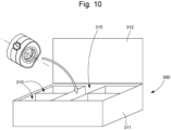
- FIG. 10 schematically represents a storage member 300 intended to receive a support element 100, 200 according to the invention.
- the storage member 300 is for example a box having an external envelope 311 of rigid design, for example made of compact cardboard, or of wood, and having a movable portion 312, for example a cover, movable between a closed position and an open position allowing access to the interior of the storage member 300.
- the storage member 300 has at least one first compartment 315 configured to receive the support element 100, 200 according to the invention described above.
- the storage member 300 may also include at least a second compartment 310 allowing the positioning of additional accessories.
Landscapes
- Adornments (AREA)
Priority Applications (1)
| Application Number | Priority Date | Filing Date | Title |
|---|---|---|---|
| EP24187780.2A EP4434407B1 (de) | 2020-09-22 | 2020-09-22 | Trägerelement für eine uhr, wie eine armbanduhr, oder ein schmuckstück |
Applications Claiming Priority (2)
| Application Number | Priority Date | Filing Date | Title |
|---|---|---|---|
| EP20197406.0A EP3970553B1 (de) | 2020-09-22 | 2020-09-22 | Halteelement einer uhr, wie beispielsweise einer armbanduhr oder eines schmuckartikels |
| EP24187780.2A EP4434407B1 (de) | 2020-09-22 | 2020-09-22 | Trägerelement für eine uhr, wie eine armbanduhr, oder ein schmuckstück |
Related Parent Applications (2)
| Application Number | Title | Priority Date | Filing Date |
|---|---|---|---|
| EP20197406.0A Division EP3970553B1 (de) | 2020-09-22 | 2020-09-22 | Halteelement einer uhr, wie beispielsweise einer armbanduhr oder eines schmuckartikels |
| EP20197406.0A Division-Into EP3970553B1 (de) | 2020-09-22 | 2020-09-22 | Halteelement einer uhr, wie beispielsweise einer armbanduhr oder eines schmuckartikels |
Publications (3)
| Publication Number | Publication Date |
|---|---|
| EP4434407A2 true EP4434407A2 (de) | 2024-09-25 |
| EP4434407A3 EP4434407A3 (de) | 2024-12-11 |
| EP4434407B1 EP4434407B1 (de) | 2026-03-18 |
Family
ID=72615562
Family Applications (2)
| Application Number | Title | Priority Date | Filing Date |
|---|---|---|---|
| EP24187780.2A Active EP4434407B1 (de) | 2020-09-22 | 2020-09-22 | Trägerelement für eine uhr, wie eine armbanduhr, oder ein schmuckstück |
| EP20197406.0A Active EP3970553B1 (de) | 2020-09-22 | 2020-09-22 | Halteelement einer uhr, wie beispielsweise einer armbanduhr oder eines schmuckartikels |
Family Applications After (1)
| Application Number | Title | Priority Date | Filing Date |
|---|---|---|---|
| EP20197406.0A Active EP3970553B1 (de) | 2020-09-22 | 2020-09-22 | Halteelement einer uhr, wie beispielsweise einer armbanduhr oder eines schmuckartikels |
Country Status (5)
| Country | Link |
|---|---|
| US (1) | US11877675B2 (de) |
| EP (2) | EP4434407B1 (de) |
| JP (1) | JP7238046B2 (de) |
| KR (1) | KR102702441B1 (de) |
| CN (1) | CN114246441B (de) |
Families Citing this family (3)
| Publication number | Priority date | Publication date | Assignee | Title |
|---|---|---|---|---|
| US12108851B1 (en) | 2023-04-04 | 2024-10-08 | James Ciaciuch | Wristwatch wrapper device |
| EP4478134A1 (de) * | 2023-06-16 | 2024-12-18 | The Swatch Group Research and Development Ltd | Vorrichtung zum aufziehen einer uhrwerke einer uhr |
| US20250098885A1 (en) * | 2023-09-22 | 2025-03-27 | Richard D. Hughes | Support Apparatus |
Family Cites Families (15)
| Publication number | Priority date | Publication date | Assignee | Title |
|---|---|---|---|---|
| BE695190A (de) * | 1966-03-14 | 1967-08-14 | ||
| US5873457A (en) | 1995-12-08 | 1999-02-23 | M. Z. Berger & Co. | Anti-theft watch box |
| DE19818100A1 (de) * | 1998-04-23 | 1999-10-28 | Kling Friedrich Gmbh | Schmuckbehälter |
| US20070151878A1 (en) | 2006-01-03 | 2007-07-05 | Nationalpak Limited | Watch box with security locker |
| EP1815772A1 (de) | 2006-02-03 | 2007-08-08 | Technew Sa | Präsentationsträger für eine Uhr und eine Armbanduhr |
| JP2009153533A (ja) | 2007-12-25 | 2009-07-16 | Casio Comput Co Ltd | 腕時計用梱包部材 |
| CH702051A1 (fr) * | 2009-10-20 | 2011-04-29 | Technew S A | Boîte pour montre-bracelet. |
| US20140061090A1 (en) * | 2012-08-29 | 2014-03-06 | Beth Amaral | Cylindrical accessory organizer |
| GB201215511D0 (en) | 2012-08-31 | 2012-10-17 | Swiss Ind Consulting And Technology Sa | A watch support suitable for use with a watch winder |
| US10602820B2 (en) * | 2014-08-08 | 2020-03-31 | Simon Bradley PHIPPS | Protective device and method for wristwatches and similar articles |
| AU2017100374B4 (en) * | 2016-07-25 | 2017-07-13 | Han Hwang | Jewellery Case |
| EP3375330B1 (de) | 2017-03-17 | 2020-04-29 | Omega SA | Interaktive präsentationsvorrichtung für gegenstände, insbesondere armbanduhren oder schmuck |
| WO2019140366A1 (en) | 2018-01-15 | 2019-07-18 | David Yurman IP LLC | Ring display fixture |
| EP3539407B1 (de) | 2018-03-13 | 2023-04-26 | Omega SA | Schatulle für uhr oder schmuckstück |
| CN209058601U (zh) * | 2018-09-04 | 2019-07-05 | 潍坊歌尔电子有限公司 | 一种手表展示座 |
-
2020
- 2020-09-22 EP EP24187780.2A patent/EP4434407B1/de active Active
- 2020-09-22 EP EP20197406.0A patent/EP3970553B1/de active Active
-
2021
- 2021-07-29 US US17/388,681 patent/US11877675B2/en active Active
- 2021-08-16 JP JP2021132188A patent/JP7238046B2/ja active Active
- 2021-08-17 KR KR1020210108029A patent/KR102702441B1/ko active Active
- 2021-09-22 CN CN202111107443.7A patent/CN114246441B/zh active Active
Also Published As
| Publication number | Publication date |
|---|---|
| CN114246441B (zh) | 2024-07-16 |
| EP3970553A1 (de) | 2022-03-23 |
| CN114246441A (zh) | 2022-03-29 |
| EP4434407A3 (de) | 2024-12-11 |
| EP3970553B1 (de) | 2025-03-26 |
| KR102702441B1 (ko) | 2024-09-03 |
| EP4434407B1 (de) | 2026-03-18 |
| US20220087449A1 (en) | 2022-03-24 |
| KR20220039565A (ko) | 2022-03-29 |
| JP7238046B2 (ja) | 2023-03-13 |
| US11877675B2 (en) | 2024-01-23 |
| JP2022051682A (ja) | 2022-04-01 |
Similar Documents
| Publication | Publication Date | Title |
|---|---|---|
| EP3970553B1 (de) | Halteelement einer uhr, wie beispielsweise einer armbanduhr oder eines schmuckartikels | |
| FR2806893A1 (fr) | Boitier du type boitier de maquillage comportant un couvercle articule | |
| WO2010040667A1 (fr) | Etui de montre | |
| CH717890A2 (fr) | Élément de support d'une pièce d'horlogerie, telle qu'une montre bracelet, ou d'un article de joaillerie. | |
| FR3019720A1 (fr) | Dispositif de conditionnement d'au moins un produit cosmetique et procede de conditionnement associe | |
| EP3539407B1 (de) | Schatulle für uhr oder schmuckstück | |
| EP3018063A1 (de) | Zusammenklappbare Box mit verschiedenen Fächern | |
| FR3089770A1 (fr) | Dispositif de conditionnement et d’application d’un bâton de produit, notamment un produit cosmétique, procédé d’insertion et d’extraction dudit bâton et kit de réalisation d’un ensemble comprenant ledit dispositif | |
| EP0836822B1 (de) | Verpackungs- und Ausstellungsvorrichtung für Schmuckobjekte oder Uhren, sowie darin benutzbares Halte- oder Aufbewahrungselement | |
| FR2494571A1 (en) | Container for contact lenses - has parallelepiped casing with drawer recessed in base and with projections on lid | |
| FR3111261A1 (fr) | Dispositif de conditionnement d’un bloc de produit cosmétique | |
| CH682290A5 (en) | Wrist watch bracelet - has holder between two sections of bracelet on opposite side to watch, designed to hold second instrument or container | |
| FR3161539A1 (fr) | Récipient cosmétique rechargeable muni d’une baïonnette à reliefs complémentaires | |
| EP4459349B1 (de) | Armband für ein tragbares objekt, wie eine uhr, mit einer vergrösserungsvorrichtung | |
| FR3161538A1 (fr) | Récipient cosmétique rechargeable muni d’une baïonnette à rampe longue | |
| FR3157362A1 (fr) | Boite de transport de bouteille avec element d’amortissement. | |
| CH720519A2 (fr) | Dispositif de conditionnement pour composants micromécaniques, et notamment pour composants horlogers | |
| FR2815609A1 (fr) | Recipient a couvercle | |
| FR2656779A1 (fr) | Boitier pour le stockage des pieces, jetons, cartes, etiquettes.. ou articles similaires pouvant etre associes a un anneau porte-cle. | |
| FR3086930A1 (fr) | Emballage anti-rayures adapte pour un objet lourd | |
| FR3035304A1 (fr) | Base de boitier munie d'un dispositif amortisseur et boitier comportant une telle base | |
| HK40072526B (zh) | 用於诸如腕表的时计或用於珠宝件的支撑元件 | |
| HK40072526A (en) | Support element for a timepiece, such as a wristwatch, or a piece of jewellery | |
| CH714743A2 (fr) | Ecrin pour pièce d’horlogerie ou de joaillerie. | |
| CH720754A2 (fr) | Bracelet pour objet portable, tel qu'une pièce d'horlogerie, comportant un dispositif grossissant |
Legal Events
| Date | Code | Title | Description |
|---|---|---|---|
| PUAI | Public reference made under article 153(3) epc to a published international application that has entered the european phase |
Free format text: ORIGINAL CODE: 0009012 |
|
| STAA | Information on the status of an ep patent application or granted ep patent |
Free format text: STATUS: THE APPLICATION HAS BEEN PUBLISHED |
|
| AC | Divisional application: reference to earlier application |
Ref document number: 3970553 Country of ref document: EP Kind code of ref document: P |
|
| AK | Designated contracting states |
Kind code of ref document: A2 Designated state(s): AL AT BE BG CH CY CZ DE DK EE ES FI FR GB GR HR HU IE IS IT LI LT LU LV MC MK MT NL NO PL PT RO RS SE SI SK SM TR |
|
| REG | Reference to a national code |
Ref country code: DE Ref legal event code: R079 Free format text: PREVIOUS MAIN CLASS: A47F0007020000 Ipc: A45C0011100000 Ref country code: DE Ref legal event code: R079 Ref document number: 602020069063 Country of ref document: DE Free format text: PREVIOUS MAIN CLASS: A47F0007020000 Ipc: A45C0011100000 |
|
| PUAL | Search report despatched |
Free format text: ORIGINAL CODE: 0009013 |
|
| AK | Designated contracting states |
Kind code of ref document: A3 Designated state(s): AL AT BE BG CH CY CZ DE DK EE ES FI FR GB GR HR HU IE IS IT LI LT LU LV MC MK MT NL NO PL PT RO RS SE SI SK SM TR |
|
| RIC1 | Information provided on ipc code assigned before grant |
Ipc: A47F 7/02 20060101ALI20241106BHEP Ipc: A45C 11/16 20060101ALI20241106BHEP Ipc: A45C 11/10 20060101AFI20241106BHEP |
|
| P01 | Opt-out of the competence of the unified patent court (upc) registered |
Free format text: CASE NUMBER: APP_9442/2025 Effective date: 20250226 |
|
| STAA | Information on the status of an ep patent application or granted ep patent |
Free format text: STATUS: REQUEST FOR EXAMINATION WAS MADE |
|
| 17P | Request for examination filed |
Effective date: 20250611 |
|
| GRAP | Despatch of communication of intention to grant a patent |
Free format text: ORIGINAL CODE: EPIDOSNIGR1 |
|
| STAA | Information on the status of an ep patent application or granted ep patent |
Free format text: STATUS: GRANT OF PATENT IS INTENDED |
|
| INTG | Intention to grant announced |
Effective date: 20251120 |
|
| GRAS | Grant fee paid |
Free format text: ORIGINAL CODE: EPIDOSNIGR3 |
|
| GRAA | (expected) grant |
Free format text: ORIGINAL CODE: 0009210 |
|
| STAA | Information on the status of an ep patent application or granted ep patent |
Free format text: STATUS: THE PATENT HAS BEEN GRANTED |
|
| AC | Divisional application: reference to earlier application |
Ref document number: 3970553 Country of ref document: EP Kind code of ref document: P |
|
| AK | Designated contracting states |
Kind code of ref document: B1 Designated state(s): AL AT BE BG CH CY CZ DE DK EE ES FI FR GB GR HR HU IE IS IT LI LT LU LV MC MK MT NL NO PL PT RO RS SE SI SK SM TR |
|
| REG | Reference to a national code |
Ref country code: CH Ref legal event code: F10 Free format text: ST27 STATUS EVENT CODE: U-0-0-F10-F00 (AS PROVIDED BY THE NATIONAL OFFICE) Effective date: 20260318 Ref country code: GB Ref legal event code: FG4D Free format text: NOT ENGLISH |
|
| REG | Reference to a national code |
Ref country code: IE Ref legal event code: FG4D Free format text: LANGUAGE OF EP DOCUMENT: FRENCH |
|
| REG | Reference to a national code |
Ref country code: DE Ref legal event code: R096 Ref document number: 602020069063 Country of ref document: DE |
|
| REG | Reference to a national code |
Ref country code: CH Ref legal event code: R17 Free format text: ST27 STATUS EVENT CODE: U-0-0-R10-R17 (AS PROVIDED BY THE NATIONAL OFFICE) Effective date: 20260427 |