EP4432798B1 - Hybride kühlanordnung für autonome und tauchgekühlte gestelle - Google Patents
Hybride kühlanordnung für autonome und tauchgekühlte gestelle Download PDFInfo
- Publication number
- EP4432798B1 EP4432798B1 EP23305366.9A EP23305366A EP4432798B1 EP 4432798 B1 EP4432798 B1 EP 4432798B1 EP 23305366 A EP23305366 A EP 23305366A EP 4432798 B1 EP4432798 B1 EP 4432798B1
- Authority
- EP
- European Patent Office
- Prior art keywords
- rack
- cooling
- fluid
- liquid
- immersion
- Prior art date
- Legal status (The legal status is an assumption and is not a legal conclusion. Google has not performed a legal analysis and makes no representation as to the accuracy of the status listed.)
- Active
Links
Images


Classifications
-
- H—ELECTRICITY
- H05—ELECTRIC TECHNIQUES NOT OTHERWISE PROVIDED FOR
- H05K—PRINTED CIRCUITS; CASINGS OR CONSTRUCTIONAL DETAILS OF ELECTRIC APPARATUS; MANUFACTURE OF ASSEMBLAGES OF ELECTRICAL COMPONENTS
- H05K7/00—Constructional details common to different types of electric apparatus
- H05K7/20—Modifications to facilitate cooling, ventilating, or heating
- H05K7/20709—Modifications to facilitate cooling, ventilating, or heating for server racks or cabinets; for data centers, e.g. 19-inch computer racks
-
- H—ELECTRICITY
- H05—ELECTRIC TECHNIQUES NOT OTHERWISE PROVIDED FOR
- H05K—PRINTED CIRCUITS; CASINGS OR CONSTRUCTIONAL DETAILS OF ELECTRIC APPARATUS; MANUFACTURE OF ASSEMBLAGES OF ELECTRICAL COMPONENTS
- H05K7/00—Constructional details common to different types of electric apparatus
- H05K7/20—Modifications to facilitate cooling, ventilating, or heating
- H05K7/20218—Modifications to facilitate cooling, ventilating, or heating using a liquid coolant without phase change in electronic enclosures
- H05K7/20236—Modifications to facilitate cooling, ventilating, or heating using a liquid coolant without phase change in electronic enclosures by immersion
-
- H—ELECTRICITY
- H05—ELECTRIC TECHNIQUES NOT OTHERWISE PROVIDED FOR
- H05K—PRINTED CIRCUITS; CASINGS OR CONSTRUCTIONAL DETAILS OF ELECTRIC APPARATUS; MANUFACTURE OF ASSEMBLAGES OF ELECTRICAL COMPONENTS
- H05K7/00—Constructional details common to different types of electric apparatus
- H05K7/20—Modifications to facilitate cooling, ventilating, or heating
- H05K7/20218—Modifications to facilitate cooling, ventilating, or heating using a liquid coolant without phase change in electronic enclosures
- H05K7/20263—Heat dissipaters releasing heat from coolant
-
- H—ELECTRICITY
- H05—ELECTRIC TECHNIQUES NOT OTHERWISE PROVIDED FOR
- H05K—PRINTED CIRCUITS; CASINGS OR CONSTRUCTIONAL DETAILS OF ELECTRIC APPARATUS; MANUFACTURE OF ASSEMBLAGES OF ELECTRICAL COMPONENTS
- H05K7/00—Constructional details common to different types of electric apparatus
- H05K7/20—Modifications to facilitate cooling, ventilating, or heating
- H05K7/20218—Modifications to facilitate cooling, ventilating, or heating using a liquid coolant without phase change in electronic enclosures
- H05K7/20272—Accessories for moving fluid, for expanding fluid, for connecting fluid conduits, for distributing fluid, for removing gas or for preventing leakage, e.g. pumps, tanks or manifolds
-
- H—ELECTRICITY
- H05—ELECTRIC TECHNIQUES NOT OTHERWISE PROVIDED FOR
- H05K—PRINTED CIRCUITS; CASINGS OR CONSTRUCTIONAL DETAILS OF ELECTRIC APPARATUS; MANUFACTURE OF ASSEMBLAGES OF ELECTRICAL COMPONENTS
- H05K7/00—Constructional details common to different types of electric apparatus
- H05K7/20—Modifications to facilitate cooling, ventilating, or heating
- H05K7/20709—Modifications to facilitate cooling, ventilating, or heating for server racks or cabinets; for data centers, e.g. 19-inch computer racks
- H05K7/20763—Liquid cooling without phase change
- H05K7/20781—Liquid cooling without phase change within cabinets for removing heat from server blades
-
- H—ELECTRICITY
- H05—ELECTRIC TECHNIQUES NOT OTHERWISE PROVIDED FOR
- H05K—PRINTED CIRCUITS; CASINGS OR CONSTRUCTIONAL DETAILS OF ELECTRIC APPARATUS; MANUFACTURE OF ASSEMBLAGES OF ELECTRICAL COMPONENTS
- H05K7/00—Constructional details common to different types of electric apparatus
- H05K7/20—Modifications to facilitate cooling, ventilating, or heating
- H05K7/20709—Modifications to facilitate cooling, ventilating, or heating for server racks or cabinets; for data centers, e.g. 19-inch computer racks
- H05K7/20763—Liquid cooling without phase change
- H05K7/2079—Liquid cooling without phase change within rooms for removing heat from cabinets
Definitions
- the present technology generally relates to cooling techniques of electronic equipment rack assemblies within datacenters.
- a hybrid cooling arrangement to service forced air, liquid block cooling of rack assemblies, and immersion cooling rack assemblies is presented.
- Datacenters house many rack-mounted electronic computing equipment, such as servers, processors, etc.
- electronic processing assemblies generate a significant amount of heat that must be pondered or at least dissipated in order avoid electronic component failures and ensure continued efficient operation.
- Document WO2022/162174A1 discloses a rack assembly using both IC and rack cooling, wherein the respective cooling arrangements are thermally coupled to each other.
- a first being an autonomous rack configuration which implements forced-air ventilation and direct liquid block cooling techniques for cooling one or more heat-generating processing assemblies.
- the autonomous rack configuration includes a first cooling loop and a second cooling loop which are thermally connected by a liquid-to-liquid heat exchanger.
- the first cooling loop contains a first heat transfer liquid conveyed to a plurality of liquid cooling blocks which are arranged in direct thermal contact with heat generating electronic processing assemblies.
- the first heat transfer liquid collects thermal energy from the electronic processing assemblies and is directed to a first side of the liquid-to-liquid heat exchanger.
- the second cooling loop contains a second heat transfer liquid which is directed to an air-to-liquid heat exchanger.
- the air-to-liquid heat exchanger transfers the thermal energy from the ambient air to the second heat transfer liquid which is then directed to the liquid-to-liquid heat exchanger.
- thermal energy is transferred from the first heat transfer liquid to the second heat transfer liquid.
- a second measure implemented to address the heat generated by the electronic processing assemblies involves immersive cooling (IC) racks.
- An IC rack includes an immersion case containing a dielectric immersion cooling fluid in which one or more electronic processing assemblies and a serpentine convection coil are submerged.
- a cooling fluid is directed through the serpentine convention coil to reduce the ambient temperature of the dielectric cooling fluid within the immersion casing.
- the cooling fluid is then directed towards the electronic processing assemblies.
- IC racks implements liquid cooling blocks in direct thermal contact with the electronic processing assemblies such that thermal energy is transferred from the electronic processing assemblies to the cooling fluid to reduce the temperature of the electronic processing assemblies.
- the now warm cooling fluid is then directed through an outlet.
- the embodiments of the present disclosure are based on developers' understanding of the drawbacks associated with conventional autonomous rack and immersive cooling systems for cooling electronic assemblies containing heat-generating components.
- the present disclosure provides a hybrid cooling arrangement in which an autonomous rack configuration and IC rack configuration are thermally connected while remaining fluidly isolated, thus providing efficient heat dissipation of the electronic processing assemblies of each system.
- a rack assembly including a cooling module for liquid-to-liquid cooling, a rack and an immersion cooling (IC) rack.
- the rack includes a rack cooling block configured to cool a rack electronic processing assembly when the rack electronic processing assembly is placed in contact with the rack cooling block and a rack fluid conduit configured to circulate a first cooling fluid through the rack cooling block and the cooling module.
- the immersion cooling (IC) rack includes a dielectric immersion cooling fluid, an IC cooling block immersed in the dielectric immersion cooling fluid and configured to cool an IC electronic processing assembly when the IC electronic processing assembly is placed in contact with the IC cooling block and an IC fluid conduit for circulating a second cooling fluid through the IC cooling block and the cooling module.
- the rack and the immersion cooling rack are thermally connected via the cooling module such that thermal energy can be transferred between the IC fluid conduit and the rack fluid conduit within the cooling module.
- the IC rack further includes a plurality of immersion casings fluidly connected in parallel with one another and configured to house the dielectric immersion cooling fluid.
- the IC cooling block includes a plurality of IC cooling blocks. Each of the plurality of IC cooling blocks are housed within each of the plurality of immersion casings.
- the IC rack further includes a plurality of IC racks immersion casings fluidly connected in series with one another and configured to house the dielectric immersion cooling fluid.
- the IC cooling block includes a plurality of IC cooling blocks. Each of the plurality of IC cooling blocks are housed within each of the plurality of immersion casings.
- the rack further includes an air-to-liquid heat exchanger configured to receive the first cooling fluid via the rack fluid conduit such that thermal energy of the first cooling fluid is transferred to ambient air.
- the air-to-liquid heat exchanger includes three air-to-liquid heat exchangers fluidly connected in series to one another, or three air-to-liquid heat exchangers fluidly connected in parallel to one another.
- a temperature of the first cooling fluid prior to flowing through the air-to-liquid heat exchanger is 27°C.
- a temperature of the first cooling fluid after exiting the air-to-liquid heat exchanger is greater than 30°C
- the temperature of the first cooling fluid after exiting the air-to-liquid heat exchanger is 35°C.
- the cooling module includes a cooling module pump and a liquid-to-liquid heat exchanger, wherein the cooling module pump is fluidly connected in series to the liquid-to-liquid heat exchanger.
- the rack cooling block is fluidly connected downstream from the cooling module, or wherein the rack cooling block is fluidly connected upstream from the cooling module.
- the rack fluid conduit and the IC fluid conduit are fluidly isolated from one another.
- thermal energy is transferred from the IC fluid conduit to the rack fluid conduit within the cooling module.
- the cooling module includes two cooling modules fluidly connected in parallel to one another.
- the rack includes a plurality of racks fluidly connected in parallel with one another.
- the rack includes a plurality of racks fluidly connected in series with one another.
- the rack is assembled with the cooling module.
- the rack further includes the rack electronic processing assembly, and wherein the IC rack further comprises the IC electronic processing assembly.
- the at least one immersion casing includes a serpentine coil submerged in the dielectric fluid and fluidly connected to the second fluid conduit.
- the rack fluid circuit includes an inlet and an outlet and wherein a temperature difference of the first cooling fluid between the inlet and the outlet is greater than 20°C.
- the temperature difference of the first cooling fluid between the inlet and the outlet is 35°C.
- a temperature of the first cooling fluid upstream from the cooling module is higher than a temperature of the first cooling fluid downstream from the cooling module.
- a temperature of the second cooling fluid upstream from the cooling module is lower than a temperature of the second cooling fluid downstream from the cooling module.
- a temperature of the first cooling fluid after exiting the cooling module is 47°C.
- a temperature of the second cooling fluid prior to entering the cooling module is 43°C.
- a temperature of the second cooling fluid after exiting the cooling module is 55°C.
- a temperature of the first cooling fluid after exiting the rack electronic processing assembly is 62°C.
- the rack assembly further includes at least one rack solenoid valve positioned on the rack fluid conduit.
- the rack assembly further includes at least one IC rack solenoid valve positioned on the IC fluid conduit.
- the IC rack further includes a cooling device.
- the rack further comprises a plurality of racks, each rack comprising a distinct rack cooling block and a distinct air-to-liquid heat exchanger and wherein the distinct rack cooling blocks are connected in series with one another and the distinct air-to-liquid heat exchangers are connected in series with one another.
- the rack further includes a plurality of racks, each rack comprising a distinct rack cooling block and a distinct air-to-liquid heat exchanger and wherein the distinct rack cooling blocks are connected in parallel with one another and the distinct air-to-liquid heat exchangers are connected in parallel with one another.
- electronic equipment may refer, but is not limited to, “servers”, “electronic devices”, “operation systems”, “systems”, “computer-based systems”, “controller units”, “monitoring devices”, “control devices” and/or any combination thereof appropriate to the relevant task at hand.
- the term "about” in the context of a given value or range refers to a value or range that is within 20%, preferably within 10%, and more preferably within 5% of the given value or range.
- the term "and/or” is to be taken as specific disclosure of each of the two specified features or components with or without the other.
- a and/or B is to be taken as specific disclosure of each of (i) A, (ii) B and (iii) A and B, just as if each is set out individually herein.
- Embodiments of the present technology each have at least one of the above-mentioned object and/or aspects, but do not necessarily have all of them. It should be understood that some aspects of the present technology that have resulted from attempting to attain the above-mentioned object may not satisfy this object and/or may satisfy other objects not specifically recited herein.
- the developers have empirically observed that the internally channeled cooling liquid of the IC rack configurations are less temperature sensitive due to the use of dielectric immersion cooling fluids. As such, the IC rack configurations are capable of tolerating, and operating with, higher temperature channeled cooling liquids.
- the hybrid cooling arrangement 10 is configured such that the first cooling circuit 104 and second cooling circuit 106 are thermally connected via at least one cooling module 108 for liquid-to-liquid cooling such that thermal energy can be transferred between the rack fluid conduit 103 of the first cooling circuit 104 of the autonomous rack 200 and the IC fluid conduit 105 of the second cooling circuit 106 of the IC rack 300.
- the autonomous rack 200 serviced by the hybrid cooling arrangement 10, receives a rack cooling fluid from a liquid cooling source 110.
- the rack cooling fluid may be a dielectric liquid or a non-dielectric liquid, for example and without limitation, water, glycol, oil, or a combination thereof.
- a cool rack cooling fluid 111 is supplied to the rack fluid conduit 103 via an inlet 107.
- the cool rack cooling fluid 111 is circulated through the rack fluid conduit 103 and is returned to the liquid cooling source 110 via an outlet 109, forming the first cooling circuit 104.
- the liquid cooling source 110 is a facility or the datacenter and the cool rack cooling fluid 111 is water.
- the autonomous rack 200 includes at least one air-to-liquid heat exchanger 112.
- the at least one air-to-liquid heat exchanger 112 is equipped with a forced air ventilation fan.
- the at least one air-to-liquid heat exchanger 112 may include a rear door heat exchanger having a plate of multiple fans and a finned heat exchanger.
- the fan plate and finned heat exchanger may be mounted on distinct hinges to allow for the opening of the finned heat exchanger while still enabling the fans to pull air.
- the fan plate may be mounted on hinges while the finned heat exchanger can be positioned on ergots.
- the at least one air-to-liquid heat exchanger 112 includes internal fluid conduits (not shown) configured to receive the cool rack cooling fluid 111 and circulate the cool rack cooling fluid 111 throughout the at least one air-to-liquid heat exchanger 112. Ambient air is pulled into the at least one air-to-liquid heat exchanger 112 and the thermal energy of the ambient air is transferred to the cool rack cooling fluid 111, resulting in cool air being expelled. Due to the transfer of thermal energy to the cool rack cooling fluid 111, the cool rack cooling fluid 111 increases in temperature and may be referred to, in its increased temperature state, as "warm rack cooling fluid 113".
- the at least one air-to-liquid heat exchanger 112 comprises three air-to-liquid heat exchangers 112 which are fluidly connected in series with one another.
- the warm rack cooling fluid 113 is directed from the at least one air-to-liquid heat exchanger 112 to the at least one cooling module 108 for liquid-to-liquid cooling.
- the at least one cooling module 108 thermally connects the autonomous rack 200 with the IC rack 300 such that thermally energy is transferred between the rack fluid conduit 103 of the first cooling circuit 104 and the IC fluid conduit 105 of the second cooling circuit 106. In other words, thermal energy is transferred between the rack cooling fluid and an IC rack cooling fluid. More specifically, the warm rack cooling fluid 113 flows through a first side 114 while the IC rack cooling fluid flows through a second side 116 of the at least one cooling module 108.
- Each of the first side 114 and the second side 116 of the at least one cooling module 108 include internal conduits (not shown) configured to receive the respective fluids of the autonomous rack 200 and IC rack 300.
- the temperature of the IC rack cooling fluid is higher than that of the warm rack cooling fluid 113, as such, thermal energy of the IC rack cooling fluid is transferred to the warm rack cooling fluid 113 within the at least one cooling module 108, cooling the IC rack cooling fluid.
- the transfer of thermal energy to the warm rack cooling fluid 113 raises the temperature of the warm rack cooling fluid 113 which may further be referred to as "warmer rack cooling fluid 115".
- the at least one cooling module 108 is assembled with the autonomous rack 200.
- the at least one cooling module 108 includes at least one pump and at least one plate heat exchanger, such that the at least one pump is fluidly connected in series with the at least one plate heat exchanger.
- the at least one cooling module 108 includes two cooling modules fluidly connected in parallel with one another. In a specific example, the two cooling modules may be mini water-cooling modules.
- the warmer rack cooling fluid 115 is directed from the at least one cooling module 108 and forwarded to one or more liquid cooling blocks 118A-118N.
- the one or more liquid cooling blocks 118A-118N are in direct thermal contact with corresponding electronic processing assemblies 120A-120N.
- Each of the one or more liquid cooling blocks 118A-118N include an internal fluid conduit (not shown) for directing the warmer rack cooling fluid 115 through the one or more liquid cooling blocks 118A-118N. It is contemplated that there may be a plurality of the one or more liquid cooling blocks 118A-118N and one or more electronic processing assemblies 120A-120N arrangements which may be fluidly connected in series or, fluidly connected in parallel, or a combination thereof (not shown).
- the warmer rack cooling fluid 115 flows through the one or more liquid cooling blocks 118A-118N, in which thermal energy is transferred from the one or more electronic processing assemblies 120A-120N to the warmer rack cooling fluid 115, thus cooling the one or more electronic processing assemblies 120A-120N.
- the temperature of the warmer rack cooling fluid 115 is raised which may further be referred to as "warmest rack cooling fluid 117".
- the warmest rack cooling fluid 117 is directed from the arrangement of the one or more liquid cooling blocks 118A-118N and one or more electronic processing assemblies 120A-120N and returned to the liquid cooling source 110 via the outlet 109.
- the cool rack cooling fluid from the liquid cooling source 110 may enter the rack fluid conduit 103 of the autonomous rack 200 between a temperature range of 25°C to 30°C, for example 27°C.
- the cool rack cooling fluid 111 is directed through the at least one air-to-liquid heat exchanger 112 in which thermal energy is transferred to the cool rack cooling fluid 111, raising the temperature to a temperature between 33°C and 38°C, for example to 35°C.
- the warm rack cooling fluid 113 is forwarded into the at least one cooling module 108 in which thermal energy is transferred from the higher temperature IC cooling fluid to the warm rack cooling fluid 113, raising the temperature to a temperature between 40°C and 45°C, for example 42°C.
- the warmer rack cooling fluid 115 is directed through the one or more liquid cooling blocks 118A-118N and corresponding one or more electronic processing assemblies 120A-120N, in which thermal energy is transferred to the warmer rack cooling fluid 115, further raising the temperature to a temperature between 60°C and 65°C, for example to 62°C, completing the first fluid circuit 104 where the warmest rack cooling fluid 117 is returned to the liquid source 110 via the outlet 109.
- the autonomous rack 200 configuration results in an ideal delta temperature, for example a temperature of 35°C, between the inlet 107 and the outlet 109 of the first fluid circuit 104.
- the warmest rack cooling fluid 117 may be conducted in areas where heating is beneficial (e.g. offices) such that thermal energy is used for heating purposes. Additionally, cooling the fluid from 62°C to 27°C, for example, is easier than cooling the fluid from 30°C to 25°C. Indeed, it has been measured that an air flow on a heat exchanger, as well as a rotation speed of a pump for conducting the rack cooling fluid, may be divided by 2 or even 3 times between these two illustrative situations. This allows for a generic cooling system to be used which reduces capital expenditure costs, and requires less power consumption and water consumption, reducing operating expenses.
- the IC rack 300 serviced by the hybrid cooling rack 10, is arranged in a closed loop configuration in which the IC rack cooling fluid 119 is circulated through the IC fluid conduit 105, forming the second cooling circuit 106.
- the closed loop configuration provides the benefit of maintaining the high quality of the IC rack cooling fluid 119.
- the IC rack cooling fluid 119 may be a dielectric liquid or a non-dielectric liquid, for example and without limitation, water, glycol, oil, or a combination thereof. In this embodiment, the IC cooling fluid is water.
- the IC rack 300 includes one or more liquid cooling blocks 126A-126N which are in direct thermal contact with corresponding electronic processing assemblies 128A-128N.
- the arrangement of the one or more liquid cooling blocks 126A-126N and one or more electronic processing assemblies 128A-128N are submerged in the dielectric immersion cooling fluid of the immersion casing 122.
- Each of the one or more liquid cooling blocks 126A-126N include an internal fluid conduit (not shown) for directing the IC rack cooling fluid 119 through the one or more liquid cooling blocks 126A-126N.
- the IC rack 300 includes a plurality of the one or more liquid cooling blocks 126A-126N and the one or more electronic processing assemblies 128A-128N arrangements positioned within a single immersion bath housing the immersion fluid 124 (not shown).
- the plurality of the one or more liquid cooling blocks 126A-126N and the one or more electronic processing assemblies 128A-128N arrangements may be fluidly connected in series, or fluidly connected in parallel, or a combination thereof.
- the IC rack 300 includes a plurality of immersion casings where each of the immersion casings houses an arrangement of the one or more liquid cooling blocks 126A-126N and the one or more electronic processing assemblies 128A-128N submerged in the immersion fluid 124 (for example, seen in Fig. 2 ).
- the IC rack 300 may further includes a cooling device 127 positioned upstream from the one or more liquid cooling blocks 126A-126N and the one or more electronic processing assemblies 128A-128N arrangement.
- the cooling device 127 is submerged within the immersion fluid 124 such that thermal energy is transferred from the immersion fluid 124 to the IC rack cooling fluid 119.
- the cooling device 127 is a finned heat exchanger submerged in the immersion fluid 124.
- the cooling device is 127 is a serpentine convection coil
- the IC rack cooling fluid 119 flows through the cooling device 127 and thermal energy is transferred from the immersion fluid 124 to the IC rack cooling fluid 119, lowering the temperature of the immersion fluid 124. As a result, the temperature of the IC rack cooling fluid 119 is raised and may now be referred to as "warm IC rack cooling fluid 121".
- the warm IC cooling fluid 121 flows through the one or more liquid cooling blocks 126A-126N, in which thermal energy is transferred from the one or more electronic processing assemblies 120A-120N. As a result, the temperature of the warm IC rack cooling fluid 121 is raised and may now be referred to as "warmer IC rack cooling fluid 123".
- the warmer IC rack cooling fluid 123 is directed from the arrangement of the one or more liquid cooling blocks 126A-126N and the one or more electronic processing assemblies 128A-128N to the at least one cooling module 108, assembled with the autonomous rack 200 and configured to transfer thermal energy between the rack fluid conduit 103 of the first cooling circuit 104 and the IC fluid conduit 105 of the second cooling circuit 106.
- the warm IC rack cooling fluid 121 flows through the second side 116 of the at least one cooling module 108 via an internal conduit (not shown).
- the warmer IC cooling fluid 123 has a higher temperature than the warm rack cooling fluid 113.
- thermal energy is transferred from the warmer IC cooling fluid 123 to the (cooler) warm rack cooling fluid 113, raising the temperature of the warm rack cooling fluid 113.
- the transfer of thermal energy from the warmer IC cooling fluid 123 cools the warmer IC cooling fluid 123 which may further be referred to as "IC cooling fluid 119".
- the IC rack cooling fluid 119 flows through the cooling device 127 between a temperature range of 43°C to 48°C, for example 43°C. Thermal energy is transferred from the immersion fluid 124 to the IC rack cooling fluid 119, raising the temperature to a temperature between 63°C to 68°C, for example 63°C.
- the warm IC rack cooling fluid 121 flows through the one or more liquid cooling blocks 126A-126N and the one or more electronic processing assemblies 128A-128N, raising the temperature to a temperature between 43°C to 48°C, for example 43°C.
- Thermal energy is transferred to the warm IC rack cooling fluid 121, raising the temperature to a temperature between 50°C to 60°C, for example to 55°C.
- the warmer IC rack cooling fluid 123 is directed through the at least one cooling module 108 where thermal energy is transferred from the warmer IC rack cooling fluid 123 to the warm rack cooling fluid 113, cooling the warmer IC rack cooling fluid 121 to a temperature between 43°C and 48°C, for example to 43°C, which is then recirculated through the second fluid circuit 106.
- These exemplary temperatures and temperature ranges provide better cooling efficiency and heat recovery without overheating the equipment.
- the fluid conduits 103, 105 which make up the first fluid circuit 104 of the autonomous rack 200 and the second fluid circuit 106 of the IC rack 300 may embody any suitable piping, tubing, conduit, or other sealed conveyance structures capable of effectively transferring and distributing fluids and may also consist of metal, rubber, or plastic materials or any combination thereof.
- the liquid cooling source 106 provides cool rack cooling fluid to the autonomous rack 200 configuration.
- the liquid cooling source 106 may correspond to an output of a heat exchanger, such as a dry cooler, which is configured to receive the warmest rack cooling fluid 117 and expel thermal energy thereof to provide the cool rack cooling fluid 111.
- the at least one air-to-liquid heat exchanger 112 may comprise a plurality of air-to-liquid heat exchangers 112 fluidly connected in series. It is contemplated, in an alternative embodiment, that the plurality of air-to-liquid heat exchangers 112 may be fluidly connected in parallel with one another. In a further alternative embodiment, some of the plurality of air-to-liquid heat exchangers 112 may be connected in series while some of the plurality of air-to-liquid heat exchangers 112 may be connected in parallel.
- the air-to-liquid heat exchanger 112 may be positioned with respect to the one or more liquid cooling blocks 118A-118N and one or more electronic processing assemblies 120A-120N arrangement. In some embodiments, the air-to-liquid heat exchanger 112 may be fluidly connected in series with the one or more liquid cooling blocks 118A-118N and one or more electronic processing assemblies 120A-120N arrangement. In an alternative embodiment, the air-to-liquid heat exchanger 112 may be fluidly connected in parallel with the one or more liquid cooling blocks 118A-118N and one or more electronic processing assemblies 120A-120N arrangement.
- the at least one cooling module 108 may be assembled with the IC rack 300 instead of the autonomous rack 200. It is further contemplated that the at least one cooling module 108 may be arranged separate from the autonomous rack 200 and the IC rack 300.
- the at least one cooling module 108 of the exemplary autonomous rack 200 configuration may include two pumps and two plate heat exchangers, where one pump is fluidly connected in series with one of the plate heat exchangers. It is appreciated that a benefit of utilizing at least one cooling module 108 with at least one pump provides a distribution of pressure drop effect between the liquid source 110 and the at least one cooling module 108. Specifically, water pressure requirements are split between the pump of the liquid source 110 and the pump of the at least one cooling module 108 within the autonomous rack 200.
- the use of multiple pumps, instead of a single pump, within the datacenter enables a smaller carbon emission footprint, reducing the capital expenditure costs, and enables easier control of fluid flow within the datacenter, reducing operating expenses.
- the at least one cooling module 108 may solely comprise at least one plate heat exchanger.
- the one or more liquid cooling blocks 118A-118N and one or more electronic processing assemblies 120A-120N are positioned downstream from the at least one cooling module 108.
- the one or more liquid cooling blocks 118A-118N and one or more electronic processing assemblies 120A-120N may instead be positioned upstream from the at least one cooling module 108.
- the warm rack cooling fluid 113 is forwarded from the at least one air-to-liquid heat exchanger 112 to the one or more liquid cooling blocks 118A-118N and one or more electronic processing assemblies 120A-120N arrangement.
- Thermal energy is transferred from the one or more electronic processing assemblies 120A-120N to the warm rack cooling fluid 113, raising the temperature of the warm rack cooling fluid 113 which may be referred to as "warmer rack cooling fluid 115".
- the warmer rack cooling fluid 115 is then directed through the first side 114 of the at least one cooling module 108.
- thermal energy is transferred from the higher temperature IC rack cooling fluid to warmer rack cooling fluid 115, raising the temperature of the warmer rack cooling fluid 115 which may be referred to as "warmest rack cooling fluid 117".
- the warmest rack cooling fluid 117 is then forwarded to the liquid cooling source 110 via the outlet 109.
- the second fluid circuit 106 is a closed loop configuration in which the IC rack cooling fluid 119 is circulated. It should be appreciated that, in an alternative embodiment, a semi-open loop configuration may be utilized. More specifically, the IC rack 300 configuration may receive and discharge the IC rack cooling fluid 119 from a cool IC rack liquid source, for example a reservoir.
- the cooling device 127 of the IC rack 300 may be a serpentine convection coil which is submerged in the immersion fluid 124 of the immersion casing 122. More specifically, the serpentine convection coil may be positioned upstream from the one or more liquid cooling blocks 126A-126N and one or more electronic processing assemblies 128A-128N arrangement.
- the serpentine convection coil is structured with multiple hollow channel coils configured to receive and internally channel the IC rack cooling fluid.
- the IC rack cooling fluid enters the serpentine convection coil and thermal energy is transferred from the ambient immersion fluid 124, reducing the temperature of the immersion fluid 124 and raising the temperature of the IC rack cooling fluid.
- the cooling device 127 comprises a combination of a serpentine convection coil and a finned heat exchanger.
- the serpentine convection coil and finned heat exchanger may be fluidly connected in series with one another or, in an alternative embodiment, may be fluidly connected in parallel. It is appreciated that the serpentine convection coil may be positioned either upstream or downstream from the finned heat exchanger.
- the hybrid cooling arrangement 10 may implement a liquid distribution infrastructure comprising a flow controller, flow distribution channel segments, temperature sensors, and flow control valves to service the liquid cooling needs of both the autonomous rack 200 and IC rack 300 configurations.
- flow control valves may comprise solenoid valves to refine control and provide load re-partition.
- a temperature sensor may be positioned along the second fluid circuit 106 upstream from the cooling module 108 such that the temperature of the IC rack cooling fluid is detected before entering the cooling module 108.
- a solenoid valve may be positioned on the first cooling circuit 104, before the cooling module 108, to modulate the flow of the rack cooling fluid into the cooling module 108 in response to the detected temperature of the IC rack cooling fluid.
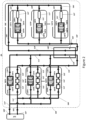
- the hybrid cooling arrangement 20 differs from the hybrid cooling arrangement 10 of Fig. 1 in that a plurality of autonomous racks 200'A-200'N are provided, and a single IC rack 300' with a plurality of immersion casings 122'A-122'N are provided in a datacenter rack assembly 102'.
- Each autonomous rack of the plurality of autonomous racks 200'A-200'N may correspond to the autonomous rack 200 of Fig. 1 .
- the IC rack 300' may correspond to the IC rack 300 of Fig. 1 .
- the datacenter rack assembly 102' may correspond to the datacenter rack assembly 102 of Fig. 1 .
- the hybrid cooling arrangement 20 services the plurality of autonomous racks 200'A-200'N and the IC rack 300', with each of the plurality autonomous racks 200'A-200'N being fluidly isolated from each of the immersion casings 122'A-122'N of the IC rack 300'.
- the plurality of autonomous racks 200'A-200'N include the rack fluid conduit 103', forming the first cooling circuit 104' and the IC rack 300' includes an IC fluid conduit 105', forming a second cooling circuit 106'.
- the rack fluid conduit 103', the first cooling circuit 104', the IC fluid conduit 105', and the second cooling circuit 106' may correspond to the rack fluid conduit 103, the first cooling circuit 104, the IC fluid conduit 105, and the second cooling circuit 106 of Fig. 1 .
- the first cooling circuit 104' is not fluidly connected to the second cooling circuit 106'.
- the plurality of autonomous racks 200'A-200'N and the IC rack 300' are thermally connected via a cooling module 108' such that thermal energy can be transferred between the rack fluid conduit 103' of the first cooling circuit 104' of the plurality of autonomous racks 200'A-200'N and the IC fluid conduit 105' of the second cooling circuit 106' of the IC rack 300'.
- the cooling module 108' may correspond to the at least one cooling module 108 of Fig. 1 .
- the plurality of autonomous racks 200'A-200'N are fluidly connected in parallel to one another and the rack fluid conduit 103' is configured to receive a cool rack cooling fluid 111' from a liquid source 110' via an inlet 107'.
- the cool rack cooling fluid 111', liquid source 110', and the inlet 107' may correspond to the cool rack cooling fluid 111, the liquid source 110, and the inlet 107 of Fig. 1 .
- the liquid source 110' may be a facility with the received cool rack cooling fluid 111' being water.
- Each of the plurality of autonomous racks 200'A-200'N include at least one air-to-liquid heat exchanger 112'.
- the at least one air-to-liquid heat exchanger 112' may be configured as any of the previously described embodiments including the at least one air-to-liquid heat exchanger 112 of Fig. 1 .
- the at least one heat exchanger 112' receives the cool rack cooling fluid 111' which flows through internal fluid conduits (not shown) of the at least one heat exchanger 112'. Thermal energy of ambient air is transferred to the cool rack cooling fluid 111' and cool air is expelled. The transfer of thermal energy to the cool rack cooling fluid 111' raises the temperature of the cool rack cooling fluid which may be referred to as "warm rack cooling fluid 113'" . It is noted that the warm rack cooling fluid 113' may correspond to the warm rack cooling fluid 113 of Fig. 1 .
- the warm rack cooling fluid is forwarded to a first side 114' of the cooling module 108' which thermally connects the rack fluid conduit 103' of the first cooling circuit 104' with the IC fluid conduit 105' of the second cooling circuit 106' for the transfer of thermal energy therebetween.
- the first side 114' may correspond to the first side 114 of Fig. 1 .
- the thermal energy of the higher temperature IC rack cooling fluid is transferred to the warm rack cooling fluid 113' within the cooling module 108', cooling the IC rack cooling fluid.
- the transfer of thermal energy to the warm rack cooling fluid 113' raises the temperature of the warm rack cooling fluid 113' which may further be referred to as "warmer rack cooling fluid 115' ".
- the warmer rack cooling fluid 115' may correspond with the warmer rack cooling fluid 115 of Fig. 1 .
- the cooling module 108' is arranged separate from the plurality of autonomous racks 200'A-200'N and the IC rack 300'. However, it is contemplated that the cooling module 108' may be assembled with any one of the plurality of autonomous racks 200'A-200'N or with the IC rack 300'.
- the warmer rack cooling fluid 115' is directed from the cooling module 108' and forwarded to one or more liquid cooling blocks 118'A-118'N which are in direct thermal contact with corresponding electronic processing assemblies 120'A-120'N. It is contemplated that the arrangement of the one or more liquid cooling blocks 118'A-118'N and the one or more electronic processing assemblies 120'A-120'N may be configured as any of the previously described embodiments, including the one or more liquid cooling blocks 118A-118N and one or more electronic processing assemblies 120A-120N of Fig. 1 .
- Thermal energy is transferred from the one or more electronic processing assemblies 120'A-120'N to the warmer rack cooling fluid 115', raising the temperature of the warmer rack cooling fluid 115' which may further be referred to as "warmest rack cooling fluid 117'". It is contemplated that the warmest rack cooling fluid 117' may correspond to the warmest rack cooling fluid 117 of Fig. 1 . The warmest rack cooling fluid 117' is then forwarded to the liquid cooling source 110' via an outlet 109'. The outlet 109' may be configured as the outlet 109 of Fig. 1 .
- the rack cooling fluid enters the first fluid circuit 104' through the inlet 107'.
- the fluid flows through the rack fluid conduit 103' of the plurality of autonomous racks 200'A-200'N.
- the autonomous racks 200'A-200'N are fluidly connected in parallel, as such, the fluid splits and flows through each of the autonomous racks 200'A-200'N in parallel.
- the fluid flows through at least one air-to-liquid heat exchanger 112'.
- the fluid is then directed through the at least one cooling module 108'.
- the fluid Upon exiting the at least one cooling module 108', the fluid is, again, split such that it flows through each of the autonomous racks 200'A-200'N in parallel. Specifically, the fluid is advanced through the one or more liquid cooling blocks 118'A-118'N and the one or more electronic processing assemblies 120'A-120'N arrangement, and eventually returns to the liquid source 110' via the outlet 109'.
- each of the plurality of immersion casings 122'A-122'N are fluidly connected in parallel with one another in a closed loop configuration which circulates an IC rack cooling fluid 119'.
- the IC rack cooling fluid 119' may correspond to the IC rack cooling fluid 119 of Fig. 1 and may be a dielectric liquid or a non-dielectric liquid, for example and without limitation, water, glycol, oil, or a combination thereof. In this embodiment, the IC cooling fluid 119' is water.
- Each of the plurality of immersion casings 122'A-122'N houses an immersion cooling fluid 124', for example a dielectric immersion cooling fluid.
- the immersion cooling fluid 124' may correspond to the immersion cooling fluid 124 of Fig. 1 .
- the arrangement of the one or more liquid cooling blocks 126'A-126'N and one or more electronic processing assemblies 128'A-128'N are submerged in the dielectric immersion cooling fluid of the immersion casing 122'A-112'N.
- the one or more liquid cooling blocks 126'A-126'N and one or more electronic processing assemblies 128'A-128'N arrangements may be a plurality of the one or more liquid cooling blocks 126'A-126'N and one or more electronic processing assemblies 128'A-128'N arrangements in each of the immersion casings 122'A-122'N and that the one or more liquid cooling blocks 126'A-126'N and one or more electronic processing assemblies 128'A-128'N may be configured in any of the previously described embodiments including the one or more liquid cooling blocks 126A-126N and one or more processing assemblies 128A-128N of Fig. 1 .
- Each of the immersion casings 122'A-122'N further includes a cooling device 127' submerged in the immersion fluid 124' and positioned upstream from the arrangement of the one or more liquid cooling blocks 126'A-126'N and one or more electronic processing assemblies 128'A-128'N.
- the cooling device 127' may correspond to the cooling device 127 of any of the previously described embodiments, including the cooling device 127 of Fig. 1 .
- the IC rack cooling fluid 119' flows through the cooling device 127' and thermal energy is transferred from the immersion fluid 124' to the IC rack cooling fluid 119', lowering the temperature of the immersion fluid 124'. As a result, the temperature of the IC rack cooling fluid 119' is raised and may now be referred to as "warm IC rack cooling fluid 121'".
- the warm IC rack cooling fluid 121' may correspond to the warm IC rack cooling fluid 121 of Fig. 1 .
- the warm IC rack cooling fluid 121' flows through the one or more liquid cooling blocks 126'A-126'N, in which thermal energy is transferred from the one or more electronic processing assemblies 120'A-120'N.
- the temperature of the warm IC rack cooling fluid 121' is raised and may now be referred to as "warmer IC rack cooling fluid 123'".
- the warmer IC rack cooling fluid 123' may correspond to the warmer IC cooling rack fluid 123 of Fig. 1 .
- the warmer IC rack cooling fluid 123' is directed from the arrangement of the one or more liquid cooling blocks 126'A-126'N and the one or more electronic processing assemblies 128'A-128'N to the second side 116' of the cooling module 108'. It is noted that the second side 116' of the cooling module 108' may correspond to the second side 116 of the at least one cooling module 108 of Fig. 1 .
- Thermal energy is transferred from the warmer IC cooling fluid 123' to the (cooler) warm rack cooling fluid 113', raising the temperature of the warm rack cooling fluid 113' (as previously described). The transfer of thermal energy from the warmer IC cooling fluid 123' cools the warmer IC cooling fluid 123' which may further be referred to as "IC cooling fluid 119'".
- the rack cooling fluid is circulated in a closed loop configuration.
- the fluid flows through the rack fluid conduit 105' of the IC rack 300'.
- the IC rack 300' is configured to have the plurality of immersion casings 122'A-122'N fluidly connected in parallel, as such, the fluid splits and flows through each of the immersion casings 122'A-122'N in parallel.
- the fluid flows through the cooling device 127'.
- the fluid is then directed through the one or more liquid cooling blocks 118'A-118'N and the one or more electronic processing assemblies 120'A-120'N arrangement housed within each of the immersion casings 122'A-122'N.
- the fluid is then advanced through the at least one cooling module 108' and recirculated through the IC rack 300' configuration.
- the IC rack 300' may include a plurality of one or more liquid cooling blocks 126'A-126'N and the one or more electronic processing assemblies 120'A-120'N arrangements housed within an immersion bath (not shown).
- the IC rack 300' may have a combination of immersion casings 122'A-122'N and an immersion bath (not shown).
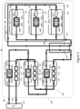
- FIG. 3 An alternative hybrid cooling arrangement 30 is depicted in Fig. 3 . It is appreciated that the plurality of autonomous racks 200'A-200'N may be fluidly connected to one another in series with one another. It is further contemplated that some of the plurality of autonomous racks 200'A-200'N may be fluidly connected in series and some of the plurality of autonomous racks 200A'-200'N may be connected in parallel (not shown).
- the plurality of immersion casings 122'A-122'N of the IC rack 300' may be fluidly connected to one another in parallel.
- the hybrid cooling arrangement 40 may include the immersion casings 122'A-122'N being fluidly connected to one another in series.
- some of the plurality of immersion casings 122'A-122'N may be fluidly connected in series and some of the plurality of immersion casings 122'A-122'N may be fluidly connected in parallel (not shown).
- the hybrid cooling arrangement may include a single autonomous rack and a plurality of IC racks thermally connected via a cooling module, such as the cooling module 108 or the cooling module 108'.
- a cooling module such as the cooling module 108 or the cooling module 108'.
- the autonomous rack, each of the plurality of IC racks, and the cooling module of this alternative embodiment may be configured as any of the autonomous rack, the IC racks, and the cooling module in the previously described embodiments.
- the disclosed embodiments of the hybrid cooling arrangement 10, 20, 30, 40 provide various benefits including, but not limited to, an increased delta temperature between an inlet 107, 107' and outlet 109, 109' of the first fluid circuit 104, 104' within the autonomous rack 200, 200'A-200'N.
- This increased in delta temperature has a significant impact on the reduction of datacenter operating expenses and capital expenditures.
- the disclosed configuration of the autonomous rack 200, 200'A-200'N allows for a distribution of pressure drop effect between the cooling liquid source 110, 110' and the at least one cooling module 108, 108'.
- the hybrid cooling arrangement 10, 20, 30, 40 requires less pumping and no sophisticated pumps, ultimately reducing costs.
- the quality of the IC rack cooling fluid can be preserved.
Landscapes
- Engineering & Computer Science (AREA)
- Microelectronics & Electronic Packaging (AREA)
- Physics & Mathematics (AREA)
- Thermal Sciences (AREA)
- Computer Hardware Design (AREA)
- General Engineering & Computer Science (AREA)
- Cooling Or The Like Of Electrical Apparatus (AREA)
Claims (15)
- Rackbaugruppe (10, 20, 30, 40), umfassend:ein Kühlmodul (108, 108') zur Flüssigkeit-zu-Flüssigkeit-Kühlung;ein Rack (200, 200'A-200'N), umfassend:einen Rack-Kühlblock (118A-118N, 118'A-118'N), der konfiguriert ist, um eine Rack-elektronische Verarbeitungsbaugruppe (120A-120N, 120'A-120'N) zu kühlen, wenn die Rack-elektronische Verarbeitungsbaugruppe in Kontakt mit dem Rack-Kühlblock gebracht wird; und,eine Rack-Fluidleitung (103, 103'), die konfiguriert ist, ein erstes Kühlfluid durch den Rack-Kühlblock und das Kühlmodul zu zirkulieren;
und,ein Tauchkühlungs-(IC-)Rack (300, 300'), umfassend:ein dielektrisches Tauchkühlfluid (124, 124');einen IC-Kühlblock (126A-126N, 126'A-126'N), der in das dielektrische Tauchkühlfluid eingetaucht ist und konfiguriert ist, eine IC-elektronische Verarbeitungseinheit (128A-128N, 128'A-128'N) zu kühlen, wenn die IC-elektronische Verarbeitungsbaugruppe in Kontakt mit dem IC-Kühlblock gebracht wird; und,eine IC-Fluidleitung (105, 105'), die konfiguriert ist, ein zweites Kühlfluid durch den IC-Kühlblock und das Kühlmodul zu zirkulieren;wobei das Rack und das Tauchkühlungs-Rack thermisch über das Kühlmodul verbunden sind, derart, dass Wärmeenergie zwischen der IC-Fluidleitung und der Rack-Fluidleitung innerhalb des Kühlmoduls übertragen werden kann. - Rackbaugruppe nach Anspruch 1, wobei das IC-Rack ferner umfasst:eine Vielzahl von Tauchgehäusen (122'A-122'N), die fluidisch parallel miteinander verbunden sind und konfiguriert sind, um das dielektrische Tauchkühlfluid aufzunehmen;wobei der IC-Kühlblock eine Vielzahl von IC-Kühlblöcken umfasst; und,wobei jeder der Vielzahl von IC-Kühlblöcken in jeweils einem der Vielzahl von Tauchgehäusen untergebracht ist.
- Rackbaugruppe nach Anspruch 1, wobei das IC-Rack ferner umfasst:eine Vielzahl von IC-Rack-Tauchgehäusen, die fluidisch in Reihe miteinander verbunden sind und konfiguriert sind, um das dielektrische Tauchkühlfluid aufzunehmen;wobei der IC-Kühlblock eine Vielzahl von IC-Kühlblöcken umfasst; und,wobei jeder der Vielzahl von IC-Kühlblöcken in jeweils einem der Vielzahl von Tauchgehäusen untergebracht ist.
- Rackbaugruppe nach einem der Patentansprüche 1 bis 3, wobei das Rack weiterhin einen Luft-zu-Flüssigkeit-Wärmetauscher (112, 112') umfasst, der konfiguriert ist, das erste Kühlfluid über die Rack-Fluidleitung aufzunehmen, derart, dass Wärmeenergie des ersten Kühlfluids an die Umgebungsluft übertragen wird.
- Rackbaugruppe nach einem der Patentansprüche 1 bis 4, wobei das Kühlmodul eine Kühlmodulpumpe und einen Flüssigkeit-zu-Flüssigkeit-Wärmetauscher umfasst, wobei die Kühlmodulpumpe fluidisch in Reihe mit dem Flüssigkeit-zu-Flüssigkeit-Wärmetauscher verbunden ist.
- Rackbaugruppe nach einem der Patentansprüche 1 bis 5, wobei der Rack-Kühlblock fluidisch stromabwärts vom Kühlmodul verbunden ist oder wobei der Rack-Kühlblock fluidisch stromaufwärts vom Kühlmodul verbunden ist.
- Rackbaugruppe nach einem der Patentansprüche 1 bis 6, wobei die Rack-Fluidleitung und die IC-Fluidleitung fluidisch voneinander isoliert sind.
- Rackbaugruppe nach einem der Patentansprüche 1 bis 7, wobei Wärmeenergie von der IC-Fluidleitung zur Rack-Fluidleitung innerhalb des Kühlmoduls übertragen wird.
- Rackbaugruppe nach einem der Patentansprüche 1 bis 8, wobei das Rack eine Vielzahl von Racks (200'A-200'N) umfasst, die fluidisch parallel zueinander verbunden sind.
- Rackbaugruppe nach einem der Patentansprüche 1 bis 9, wobei das Rack eine Vielzahl von Racks umfasst, die fluidisch in Reihe miteinander verbunden sind.
- Rackbaugruppe nach einem der Patentansprüche 1 bis 10, wobei das Rack ferner die Rack-elektronische Verarbeitungsbaugruppe (120A-120N, 120'A-120'N) umfasst und wobei das IC-Rack ferner die IC-elektronische Verarbeitungsbaugruppe (128A-128N, 128'A-128'N) umfasst.
- Rackbaugruppe nach einem der Patentansprüche 1 bis 11, wobei das IC-Rack ferner eine Kühlvorrichtung (127, 127') umfasst.
- Rackbaugruppe nach einem der Patentansprüche 1 bis 12, wobei der Rack-Fluidkreislauf einen Einlass (107, 107') und einen Auslass (109, 109') umfasst und wobei eine Temperaturdifferenz des ersten Kühlfluids zwischen dem Einlass und dem Auslass größer als 20°C ist.
- Rackbaugruppe nach Anspruch 1, wobei das Rack ferner eine Vielzahl von Racks umfasst, wobei jedes Rack einen separaten Rack-Kühlblock (118A-118N, 118'A-118'N) und einen separaten Luft-zu-Flüssigkeit-Wärmetauscher (112, 112') umfasst und wobei die separaten Rack-Kühlblöcke (118A-118N, 118'A-118'N) in Reihe miteinander verbunden sind und die separaten Luft-zu-Flüssigkeit-Wärmetauscher (112, 112') in Reihe miteinander verbunden sind.
- Rackbaugruppe nach Anspruch 1, wobei das Rack ferner eine Vielzahl von Racks umfasst, wobei jedes Rack einen separaten Rack-Kühlblock (118A-118N, 118'A-118'N) und einen separaten Luft-zu-Flüssigkeit-Wärmetauscher (112, 112') umfasst und wobei die separaten Rack-Kühlblöcke (118A-118N, 118'A-118'N) parallel zueinander verbunden sind und die separaten Luft-zu-Flüssigkeit-Wärmetauscher (112, 112') parallel zueinander verbunden sind.
Priority Applications (3)
| Application Number | Priority Date | Filing Date | Title |
|---|---|---|---|
| EP23305366.9A EP4432798B1 (de) | 2023-03-16 | 2023-03-16 | Hybride kühlanordnung für autonome und tauchgekühlte gestelle |
| US18/588,745 US20240314972A1 (en) | 2023-03-16 | 2024-02-27 | Hybrid cooling arrangement for autonomous and immersion cooled racks |
| CN202410298869.2A CN118678613A (zh) | 2023-03-16 | 2024-03-15 | 机架组件 |
Applications Claiming Priority (1)
| Application Number | Priority Date | Filing Date | Title |
|---|---|---|---|
| EP23305366.9A EP4432798B1 (de) | 2023-03-16 | 2023-03-16 | Hybride kühlanordnung für autonome und tauchgekühlte gestelle |
Publications (2)
| Publication Number | Publication Date |
|---|---|
| EP4432798A1 EP4432798A1 (de) | 2024-09-18 |
| EP4432798B1 true EP4432798B1 (de) | 2025-04-23 |
Family
ID=85792594
Family Applications (1)
| Application Number | Title | Priority Date | Filing Date |
|---|---|---|---|
| EP23305366.9A Active EP4432798B1 (de) | 2023-03-16 | 2023-03-16 | Hybride kühlanordnung für autonome und tauchgekühlte gestelle |
Country Status (3)
| Country | Link |
|---|---|
| US (1) | US20240314972A1 (de) |
| EP (1) | EP4432798B1 (de) |
| CN (1) | CN118678613A (de) |
Family Cites Families (9)
| Publication number | Priority date | Publication date | Assignee | Title |
|---|---|---|---|---|
| JP6790690B2 (ja) * | 2016-10-04 | 2020-11-25 | 富士通株式会社 | 情報処理システム、及び情報処理システムの制御方法 |
| KR102812837B1 (ko) * | 2019-05-21 | 2025-05-26 | 아이서톱 그룹 리미티드 | 전자 모듈용 냉각 시스템 |
| US11019752B2 (en) * | 2019-06-20 | 2021-05-25 | Baidu Usa Llc | Cooling module design for servers |
| US11392184B2 (en) * | 2020-09-25 | 2022-07-19 | Microsoft Technology Licensing, Llc | Disaggregated computer systems |
| NL2027460B1 (en) * | 2021-01-29 | 2022-09-02 | Solo30 B V | Hybrid datacentre module |
| EP4316220A1 (de) * | 2021-04-01 | 2024-02-07 | Ovh | Hybrides flüssigkeitskühlsystem mit leckerkennung |
| US11864357B2 (en) * | 2021-05-25 | 2024-01-02 | Toyota Motor Engineering And Manufacturing North America, Inc. | Double-sided cooling cold plates with overhanging heat sinks and through body busbar for high-power density power electronics |
| WO2023086451A1 (en) * | 2021-11-12 | 2023-05-19 | Jetcool Technologies Inc. | Liquid-in-liquid cooling system for electronic components |
| US11943904B2 (en) * | 2022-05-31 | 2024-03-26 | GE Grid GmbH | Hybrid thermosyphon with immersion cooled evaporator |
-
2023
- 2023-03-16 EP EP23305366.9A patent/EP4432798B1/de active Active
-
2024
- 2024-02-27 US US18/588,745 patent/US20240314972A1/en active Pending
- 2024-03-15 CN CN202410298869.2A patent/CN118678613A/zh active Pending
Also Published As
| Publication number | Publication date |
|---|---|
| CN118678613A (zh) | 2024-09-20 |
| EP4432798A1 (de) | 2024-09-18 |
| US20240314972A1 (en) | 2024-09-19 |
Similar Documents
| Publication | Publication Date | Title |
|---|---|---|
| US11083110B2 (en) | Multifunction coolant manifold structures | |
| US11019755B2 (en) | Effectiveness-weighted control of cooling system components | |
| US20220322575A1 (en) | Hybrid immersion cooling system for rack-mounted electronic assemblies | |
| EP2609800B1 (de) | Flüssigkeitskühlsystem für einen server | |
| EP3736661B1 (de) | Kühlung von elektronischen vorrichtungen in einem datenzentrum | |
| US8934250B2 (en) | Immersion-cooling of selected electronic component(s) mounted to printed circuit board | |
| US8760863B2 (en) | Multi-rack assembly with shared cooling apparatus | |
| US8879257B2 (en) | Combined power and cooling rack supporting an electronics rack(s) | |
| US9811097B2 (en) | Environmental control of liquid cooled electronics | |
| EP3531812A1 (de) | Kühlsystem für einen server | |
| US20120118534A1 (en) | Multimodal cooling apparatus for an electronic system | |
| EP4432798B1 (de) | Hybride kühlanordnung für autonome und tauchgekühlte gestelle | |
| EP4142444B1 (de) | Verfahren zur steuerung eines kühlsystems zur autonomen kühlung eines racks | |
| US20250212370A1 (en) | Prioritized liquid cooling arrangements for datacenter server racks | |
| US12513864B2 (en) | Hybrid liquid cooling arrangement for autonomous and immersion cooled racks | |
| US20220124941A1 (en) | Device for cooling high-performance computers or high-performance circuits, with temperature control | |
| CN120417306A (zh) | 热调节系统、热调节用套件、数据中心系统和备用系统 | |
| HK1187191B (en) | Liquid cooling system for a server |
Legal Events
| Date | Code | Title | Description |
|---|---|---|---|
| PUAI | Public reference made under article 153(3) epc to a published international application that has entered the european phase |
Free format text: ORIGINAL CODE: 0009012 |
|
| STAA | Information on the status of an ep patent application or granted ep patent |
Free format text: STATUS: REQUEST FOR EXAMINATION WAS MADE |
|
| 17P | Request for examination filed |
Effective date: 20231109 |
|
| AK | Designated contracting states |
Kind code of ref document: A1 Designated state(s): AL AT BE BG CH CY CZ DE DK EE ES FI FR GB GR HR HU IE IS IT LI LT LU LV MC ME MK MT NL NO PL PT RO RS SE SI SK SM TR |
|
| GRAP | Despatch of communication of intention to grant a patent |
Free format text: ORIGINAL CODE: EPIDOSNIGR1 |
|
| STAA | Information on the status of an ep patent application or granted ep patent |
Free format text: STATUS: GRANT OF PATENT IS INTENDED |
|
| GRAS | Grant fee paid |
Free format text: ORIGINAL CODE: EPIDOSNIGR3 |
|
| INTG | Intention to grant announced |
Effective date: 20250206 |
|
| GRAA | (expected) grant |
Free format text: ORIGINAL CODE: 0009210 |
|
| STAA | Information on the status of an ep patent application or granted ep patent |
Free format text: STATUS: THE PATENT HAS BEEN GRANTED |
|
| AK | Designated contracting states |
Kind code of ref document: B1 Designated state(s): AL AT BE BG CH CY CZ DE DK EE ES FI FR GB GR HR HU IE IS IT LI LT LU LV MC ME MK MT NL NO PL PT RO RS SE SI SK SM TR |
|
| REG | Reference to a national code |
Ref country code: GB Ref legal event code: FG4D |
|
| REG | Reference to a national code |
Ref country code: CH Ref legal event code: EP |
|
| P01 | Opt-out of the competence of the unified patent court (upc) registered |
Free format text: CASE NUMBER: APP_15044/2025 Effective date: 20250328 |
|
| REG | Reference to a national code |
Ref country code: DE Ref legal event code: R096 Ref document number: 602023003086 Country of ref document: DE |
|
| REG | Reference to a national code |
Ref country code: IE Ref legal event code: FG4D |
|
| REG | Reference to a national code |
Ref country code: NL Ref legal event code: MP Effective date: 20250423 |
|
| PG25 | Lapsed in a contracting state [announced via postgrant information from national office to epo] |
Ref country code: NL Free format text: LAPSE BECAUSE OF FAILURE TO SUBMIT A TRANSLATION OF THE DESCRIPTION OR TO PAY THE FEE WITHIN THE PRESCRIBED TIME-LIMIT Effective date: 20250423 |
|
| REG | Reference to a national code |
Ref country code: AT Ref legal event code: MK05 Ref document number: 1789106 Country of ref document: AT Kind code of ref document: T Effective date: 20250423 |
|
| PG25 | Lapsed in a contracting state [announced via postgrant information from national office to epo] |
Ref country code: FI Free format text: LAPSE BECAUSE OF FAILURE TO SUBMIT A TRANSLATION OF THE DESCRIPTION OR TO PAY THE FEE WITHIN THE PRESCRIBED TIME-LIMIT Effective date: 20250423 Ref country code: PT Free format text: LAPSE BECAUSE OF FAILURE TO SUBMIT A TRANSLATION OF THE DESCRIPTION OR TO PAY THE FEE WITHIN THE PRESCRIBED TIME-LIMIT Effective date: 20250825 Ref country code: ES Free format text: LAPSE BECAUSE OF FAILURE TO SUBMIT A TRANSLATION OF THE DESCRIPTION OR TO PAY THE FEE WITHIN THE PRESCRIBED TIME-LIMIT Effective date: 20250423 |
|
| REG | Reference to a national code |
Ref country code: LT Ref legal event code: MG9D |
|
| PG25 | Lapsed in a contracting state [announced via postgrant information from national office to epo] |
Ref country code: GR Free format text: LAPSE BECAUSE OF FAILURE TO SUBMIT A TRANSLATION OF THE DESCRIPTION OR TO PAY THE FEE WITHIN THE PRESCRIBED TIME-LIMIT Effective date: 20250724 Ref country code: NO Free format text: LAPSE BECAUSE OF FAILURE TO SUBMIT A TRANSLATION OF THE DESCRIPTION OR TO PAY THE FEE WITHIN THE PRESCRIBED TIME-LIMIT Effective date: 20250723 |
|
| PG25 | Lapsed in a contracting state [announced via postgrant information from national office to epo] |
Ref country code: PL Free format text: LAPSE BECAUSE OF FAILURE TO SUBMIT A TRANSLATION OF THE DESCRIPTION OR TO PAY THE FEE WITHIN THE PRESCRIBED TIME-LIMIT Effective date: 20250423 |
|
| PG25 | Lapsed in a contracting state [announced via postgrant information from national office to epo] |
Ref country code: BG Free format text: LAPSE BECAUSE OF FAILURE TO SUBMIT A TRANSLATION OF THE DESCRIPTION OR TO PAY THE FEE WITHIN THE PRESCRIBED TIME-LIMIT Effective date: 20250423 |
|
| PG25 | Lapsed in a contracting state [announced via postgrant information from national office to epo] |
Ref country code: HR Free format text: LAPSE BECAUSE OF FAILURE TO SUBMIT A TRANSLATION OF THE DESCRIPTION OR TO PAY THE FEE WITHIN THE PRESCRIBED TIME-LIMIT Effective date: 20250423 |
|
| PG25 | Lapsed in a contracting state [announced via postgrant information from national office to epo] |
Ref country code: AT Free format text: LAPSE BECAUSE OF FAILURE TO SUBMIT A TRANSLATION OF THE DESCRIPTION OR TO PAY THE FEE WITHIN THE PRESCRIBED TIME-LIMIT Effective date: 20250423 |
|
| PG25 | Lapsed in a contracting state [announced via postgrant information from national office to epo] |
Ref country code: RS Free format text: LAPSE BECAUSE OF FAILURE TO SUBMIT A TRANSLATION OF THE DESCRIPTION OR TO PAY THE FEE WITHIN THE PRESCRIBED TIME-LIMIT Effective date: 20250723 |
|
| PG25 | Lapsed in a contracting state [announced via postgrant information from national office to epo] |
Ref country code: IS Free format text: LAPSE BECAUSE OF FAILURE TO SUBMIT A TRANSLATION OF THE DESCRIPTION OR TO PAY THE FEE WITHIN THE PRESCRIBED TIME-LIMIT Effective date: 20250823 |
|
| PG25 | Lapsed in a contracting state [announced via postgrant information from national office to epo] |
Ref country code: LV Free format text: LAPSE BECAUSE OF FAILURE TO SUBMIT A TRANSLATION OF THE DESCRIPTION OR TO PAY THE FEE WITHIN THE PRESCRIBED TIME-LIMIT Effective date: 20250423 |
|
| PG25 | Lapsed in a contracting state [announced via postgrant information from national office to epo] |
Ref country code: DK Free format text: LAPSE BECAUSE OF FAILURE TO SUBMIT A TRANSLATION OF THE DESCRIPTION OR TO PAY THE FEE WITHIN THE PRESCRIBED TIME-LIMIT Effective date: 20250423 Ref country code: SM Free format text: LAPSE BECAUSE OF FAILURE TO SUBMIT A TRANSLATION OF THE DESCRIPTION OR TO PAY THE FEE WITHIN THE PRESCRIBED TIME-LIMIT Effective date: 20250423 |
|
| PG25 | Lapsed in a contracting state [announced via postgrant information from national office to epo] |
Ref country code: CZ Free format text: LAPSE BECAUSE OF FAILURE TO SUBMIT A TRANSLATION OF THE DESCRIPTION OR TO PAY THE FEE WITHIN THE PRESCRIBED TIME-LIMIT Effective date: 20250423 |
|
| PG25 | Lapsed in a contracting state [announced via postgrant information from national office to epo] |
Ref country code: EE Free format text: LAPSE BECAUSE OF FAILURE TO SUBMIT A TRANSLATION OF THE DESCRIPTION OR TO PAY THE FEE WITHIN THE PRESCRIBED TIME-LIMIT Effective date: 20250423 |
|
| REG | Reference to a national code |
Ref country code: DE Ref legal event code: R097 Ref document number: 602023003086 Country of ref document: DE |
|
| PG25 | Lapsed in a contracting state [announced via postgrant information from national office to epo] |
Ref country code: SK Free format text: LAPSE BECAUSE OF FAILURE TO SUBMIT A TRANSLATION OF THE DESCRIPTION OR TO PAY THE FEE WITHIN THE PRESCRIBED TIME-LIMIT Effective date: 20250423 |
|
| PG25 | Lapsed in a contracting state [announced via postgrant information from national office to epo] |
Ref country code: IT Free format text: LAPSE BECAUSE OF FAILURE TO SUBMIT A TRANSLATION OF THE DESCRIPTION OR TO PAY THE FEE WITHIN THE PRESCRIBED TIME-LIMIT Effective date: 20250423 |
|
| PLBE | No opposition filed within time limit |
Free format text: ORIGINAL CODE: 0009261 |
|
| STAA | Information on the status of an ep patent application or granted ep patent |
Free format text: STATUS: NO OPPOSITION FILED WITHIN TIME LIMIT |
|
| REG | Reference to a national code |
Ref country code: CH Ref legal event code: L10 Free format text: ST27 STATUS EVENT CODE: U-0-0-L10-L00 (AS PROVIDED BY THE NATIONAL OFFICE) Effective date: 20260304 |