EP4432774A2 - Verfahren für dfs und radarvermeidungsverwaltung in mehrknotennetzwerken - Google Patents
Verfahren für dfs und radarvermeidungsverwaltung in mehrknotennetzwerken Download PDFInfo
- Publication number
- EP4432774A2 EP4432774A2 EP24191773.1A EP24191773A EP4432774A2 EP 4432774 A2 EP4432774 A2 EP 4432774A2 EP 24191773 A EP24191773 A EP 24191773A EP 4432774 A2 EP4432774 A2 EP 4432774A2
- Authority
- EP
- European Patent Office
- Prior art keywords
- radar
- node
- wireless device
- dfs
- channel
- Prior art date
- Legal status (The legal status is an assumption and is not a legal conclusion. Google has not performed a legal analysis and makes no representation as to the accuracy of the status listed.)
- Pending
Links
Images


Classifications
-
- H—ELECTRICITY
- H04—ELECTRIC COMMUNICATION TECHNIQUE
- H04W—WIRELESS COMMUNICATION NETWORKS
- H04W16/00—Network planning, e.g. coverage or traffic planning tools; Network deployment, e.g. resource partitioning or cells structures
- H04W16/14—Spectrum sharing arrangements between different networks
-
- H—ELECTRICITY
- H04—ELECTRIC COMMUNICATION TECHNIQUE
- H04W—WIRELESS COMMUNICATION NETWORKS
- H04W24/00—Supervisory, monitoring or testing arrangements
- H04W24/08—Testing, supervising or monitoring using real traffic
-
- H—ELECTRICITY
- H04—ELECTRIC COMMUNICATION TECHNIQUE
- H04W—WIRELESS COMMUNICATION NETWORKS
- H04W72/00—Local resource management
- H04W72/04—Wireless resource allocation
- H04W72/044—Wireless resource allocation based on the type of the allocated resource
- H04W72/0453—Resources in frequency domain, e.g. a carrier in FDMA
-
- H—ELECTRICITY
- H04—ELECTRIC COMMUNICATION TECHNIQUE
- H04W—WIRELESS COMMUNICATION NETWORKS
- H04W72/00—Local resource management
- H04W72/20—Control channels or signalling for resource management
- H04W72/27—Control channels or signalling for resource management between access points
-
- H—ELECTRICITY
- H04—ELECTRIC COMMUNICATION TECHNIQUE
- H04W—WIRELESS COMMUNICATION NETWORKS
- H04W72/00—Local resource management
- H04W72/50—Allocation or scheduling criteria for wireless resources
- H04W72/54—Allocation or scheduling criteria for wireless resources based on quality criteria
- H04W72/541—Allocation or scheduling criteria for wireless resources based on quality criteria using the level of interference
-
- H—ELECTRICITY
- H04—ELECTRIC COMMUNICATION TECHNIQUE
- H04W—WIRELESS COMMUNICATION NETWORKS
- H04W8/00—Network data management
- H04W8/005—Discovery of network devices, e.g. terminals
-
- H—ELECTRICITY
- H04—ELECTRIC COMMUNICATION TECHNIQUE
- H04W—WIRELESS COMMUNICATION NETWORKS
- H04W84/00—Network topologies
- H04W84/02—Hierarchically pre-organised networks, e.g. paging networks, cellular networks, WLAN [Wireless Local Area Network] or WLL [Wireless Local Loop]
- H04W84/10—Small scale networks; Flat hierarchical networks
- H04W84/12—WLAN [Wireless Local Area Networks]
-
- H—ELECTRICITY
- H04—ELECTRIC COMMUNICATION TECHNIQUE
- H04W—WIRELESS COMMUNICATION NETWORKS
- H04W84/00—Network topologies
- H04W84/18—Self-organising networks, e.g. ad-hoc networks or sensor networks
- H04W84/20—Leader-follower arrangements
-
- H—ELECTRICITY
- H04—ELECTRIC COMMUNICATION TECHNIQUE
- H04W—WIRELESS COMMUNICATION NETWORKS
- H04W92/00—Interfaces specially adapted for wireless communication networks
- H04W92/16—Interfaces between hierarchically similar devices
- H04W92/20—Interfaces between hierarchically similar devices between access points
Definitions
- This disclosure relates to DFS (Dynamic Frequency Selection) and radar-avoidance management in wireless networks.
- DFS Dynamic Frequency Selection
- radar-avoidance management in wireless networks.
- the disclosure relates to DFS and radar-avoidance management in multi-node networks.
- DFS dynamic frequency selection
- Soyak et al. U.S. Patent Publication No. 2013/0194944 discloses a method of detecting radar and avoiding the radar interference. The entire contents of Soyak et al. are incorporated herein by reference.
- Master devices and slave devices with radar detection capability are nodes that are subject to DFS radar-detection regulations.
- Examples of the master devices are Access Points (APs) or Universal Repeaters (URs).
- Examples of the slave devices without radar-detection capability are wireless stations, i.e., wireless clients.
- slave nodes may not possess radar detection capability and they may be subject to the "slave without radar detection" rules of the DFS regulations. In some rare cases, however, slave nodes are capable of the radar detection capability.
- wireless devices like APs, URs, wireless stations, and wireless clients may comprise processing circuitry, a memory, communication circuitry including radio-frequency (RF) transmitters/receivers.
- processing circuitry may include any suitable type of processing circuitry, such as one or more of a general-purpose processor (for example, an ARM-based processor), a chipset of a communications interface, an application-specific integrated circuit (ASIC), and a Field-Programmable Gate Array (FPGA).
- Memory may include any suitable type of volatile and non-volatile memory, such as random-access memory (RAM), read-only memory (ROM), flash memory, cloud storage, network accessible storage (NAS), or others.
- Communications circuitry may include any suitable type of communications circuitry to send or receive signals of certain protocols, such as Wi-Fi, Ethernet, Long-Term Evolution interface, Bluetooth Interface, Infrared (IR), Power Line Communication (PLC), Multiplexing over Coaxial (MoCA) or others. Persons having ordinary skill in the art will further understand that relevant RF transmitters/receivers are used to carry out such signals.
- protocols such as Wi-Fi, Ethernet, Long-Term Evolution interface, Bluetooth Interface, Infrared (IR), Power Line Communication (PLC), Multiplexing over Coaxial (MoCA) or others.
- IR Infrared
- PLC Power Line Communication
- MoCA Multiplexing over Coaxial
- DFS-aware operation is rather straightforward for a wireless network with a single-node
- the DFS-aware operation in multi-node wireless networks is very complex.
- An example of single-node wireless networks is a Wi-Fi Basic Service Set (BSS), which comprises an AP with radar detection capability such as a master node, and one or more wireless stations without radar-detection capability such as slave devices.
- BSS Wi-Fi Basic Service Set
- multi-node wireless networks is a wireless mesh network, a wireless network comprising an AP and at least one URs (or Repeaters), and a wireless network that comprises APs connected with each other through wired communications, such as Ethernet, MoCA (Multiplexing over Co-Axial), or PLC (Power Line Communication).
- a multi-node wireless network may make up an Extended Service Set (ESS) according to IEEE 802.11 standards.
- a "node” in the multi-node wireless network may be a device that provides service to client devices (stations).
- client devices stations
- AP, UR, and wireless gateway (GW) are the nodes, whereas mobile clients may be stations.
- the node may be a device that comprises the wireless network, and it may be utilized as a wireless access point.
- each node in the network is spatially distributed, and hence it has a different view of the wireless medium. Because each node in the network is spatially distributed, one node detects radars while other nodes may not detect the same radars. In such cases, it is of paramount importance for the entire network to cease transmission in the radar-detected frequency.
- the DFS management includes methods for operating a multi-node wireless network, as if it is a single-node network from the perspective of DFS regulations.
- Wireless communication devices operating within wireless mesh network or repeater network are adapted to detect radar; send or receive radar-detected and/or channel switch announcement (CSA) messages; to dynamically switch between master mode and slave mode; and to operate in different channels.
- CSA channel switch announcement
- a node employs two operational modes: master and slave.
- the Node can switch between these two operational modes during run-time, but it can be in one of these modes at a time. That is to say, both modes cannot be active at the same time.
- master When a node is operating as "master,” it has radar-detection capability, and it is subject to DFS regulations for master devices.
- slave When a node is operating as "slave,” it is subject to DFS regulations for slave devices. According to the regulations, a slave device has to follow a master device for DFS-related operations.
- a master node detects radar, it immediately (within the duration allowed by the DFS regulations) informs slave devices (that are associated with the master node) about the channel change that is to happen, ceases its transmissions in the radar-detected frequency, and switches to an available, non-radar, channel. Slave devices must obey the messages coming from the master node.
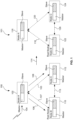
- the elements 100 and 101 denote wireless mesh networks operating in a first channel and a second channel, respectively.
- the elements 102 and 116 denote Node-A.
- the elements 110 and 122 denote Node-B.
- the elements 112 and 124 denote Node-C.
- the elements 106 and 108 denote signals transmitted over communication paths 107/118, 103/120, and 113/126, such as frequency bands, channels, or other equivalents.
- Note-A 102 When Note-A 102 detects radar, it sends channel switch announcement (CSA) messages to other nodes, Node-B 110 and Node-C 112, which are not detecting the radar. After receiving the messages from Note-A 102, Node-B 110 and Node-C 112 switch to an available channel. 114.
- the element 101 shows a wireless mesh network operating in the available channel.
- a node selects its modes of operation, master or slave, dynamically. If the node detects radar in a DFS channel, it informs associated stations about a channel to be switched, and it informs its peer nodes about the radar and the channel to be switched by sending a radar-detected message and a CSA message. However, peer nodes may fail to notice those messages, as depicted in FIG. 2 .
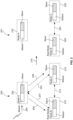
- the elements 200 and 201 denote wireless mesh networks.
- the elements 202/218, 210/220, 212/222 denote Node-A, Node-B, Node-C, respectively.
- the elements 206 and 208 denote signals transmitted over communication paths 203, 207, 214, 224, such as frequency bands, channels, or other equivalents.
- Node-B 210 and Node-C 212 fail to receive Node-A's CSA messages, thus they continue communicating in their current channel(s).
- the wireless mesh network loses it connectivity because Node-A 218 is operating in one channel, while Node-B 220 and Node-C 222 are operating in a different channel.
- a node like Node-A in FIG. 2 switches to slave mode and connects to its peer nodes to inform them about the radar.
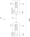
- the elements 300 and 301 denote wireless mesh networks.
- the elements 302/312, 304/316, 306/318 denote Node-A, Node-B, Node-C, respectively.
- the element 314 denotes signal transmitted over a communication path 315, such as frequency bands, channels, or other equivalents.
- the elements 308/320 are also communication paths.
- Node-A 302 in the network 300 switches to slave mode and scans other channels to find the root node or a node connected to the root node.
- Node-C 306 is connected to the root node, Node-B 304. After finding Node-C 306, Node-A 302 connects to Node-C 306 as a slave. 310. Then, Node-A 312 sends radar-detected message in an effort to force Node-C 318 to abandon the radar-detected channel 314.
- the rationale behind switching to slave mode is to be able to inform the peer nodes about the detected radar, and force them to abandon the radar-detected channel for at least the duration of non-occupancy period, for example, as defined in the ETSI and FCC DFS regulations.
- FIG. 4 illustrates how Node-C in FIG. 3 reacts after receiving radar-detected message from Node-A.
- the elements 400 and 401 denote wireless mesh networks.
- the elements 402/414, 406/418, 408/420 denote Node-A, Node-B, Node-C, respectively.
- the elements 404, 410 denote signals transmitted over communication paths 405, 422, 424, such as frequency bands, channels, or other equivalents.
- Node-C 402 triggers transmission of radar-detected and CSA messages to Node-A 402 and Node-B 406. Then, Node-B 406 and Node-C switch to an available channel. 412. Then, Node-A 402, Node-B 406, and Node-C 401 are operating in the same channel. 401. Afterward, as illustrated in FIG. 5 , the wireless mesh network 500 is re-established because all the nodes can communicate with each other (504, 506, and 512). Node-A 502 reverts to master mode.
- the element 500 and 401 denote a wireless mesh network.
- the elements 502, 508, 510 denote Node-A, Node-B, Node-C, respectively.
- the elements 504, 506, 512 denote communication paths, such as frequency bands, channels, or other equivalents.
- a wireless mesh network comprises 3 APs (Node-A, Node-B, and Node-C). These three APs operate in a non-DFS channel, and they are scheduled to switch to a DFS channel. Upon switching to the DFS channel, these three APs start Channel Availability Check (CAC). According to the DFS regulations, CAC is required to be carried out to mark a DFS channel as available. If no radars are detected during the CAC, the master device can start transmitting in the channel. No transmissions are allowed during CAC.
- CAC Channel Availability Check
- the stringent regulations on how to pursue the CAC make the multi-node CAC process complex.
- the APs detect radar during the CAC, but the others do not detect the radar, there is no way, during the CAC procedure for the APs that have detected radar, to inform the other APs about the presence of the radar because no transmissions are allowed during the CAC procedure.
- Node-A detects radar during the CAC and switches to an available channel
- Node-B and Node-C do not detect the radar and continue to stay in their current channel. In such a case, the network loses its connectivity, since the nodes are now operating in different channels.
- Node-A has switched to a predetermined non-DFS channel upon reception of radar.
- Node-B and Node-C continue operating in the DFS channels since they have not detected the radar in their operating channels.
- This disclosure provides methods to overcome these two major problems by dynamically managing the operational mode of the nodes, and by employing control messaging among the nodes to inform one another about the presence of radar and channel switch announcements.
- nodes can set-up a wireless network through various methods.
- a multi-node network one of the nodes is regarded as the root-node.
- the root-node can be any one of the nodes in the multi-node network.
- the root-node can be changed as needed.
- a node is assigned to a root-node in the network as required.
- the root-node always operates in master mode, whereas the other nodes may change their operational modes during run-time as needed.
- the root-node is the gateway mesh access point (GW MAP).
- GW MAP gateway mesh access point
- nodes may operate in master mode. Nodes continuously monitor their operating frequencies for possible radars. According to DFS regulations, this is called in-service monitoring. If a node detects radar in its operating channel, it (i) sends a "radar-detected message" to its peer-nodes, (ii) sends Channel Switch Announcement (CSA) or Extended CSA (ECSA) message to its peer-nodes and its stations, (iii) buffers all ongoing traffic and ceases all transmissions in the radar-detected channel, (iv) marks the channel as unavailable for a duration of non-occupancy period (as defined in the DFS regulations), (v) changes its operational mode to slave, and (vi) switches to the available channel it has announced in its CSA or ECSA (Extended CSA) message.
- CSA Channel Switch Announcement
- ECSA Extended CSA
- This channel can be a non-DFS channel or a DFS channel which had been found to be radar-free via Channel Availability Check (CAC) or off-channel CAC.
- CAC Channel Availability Check
- the node If the node can reestablish connection with the root-node in the switched channel, then the node reverts to master mode, and continues its normal operation. However, if the node cannot reestablish connection with the root-node, then the node starts scanning other channels to find the root-node, or a node (in master mode) that is connected to the root-node through single hop or multiple hops.
- the node In the channel scan, the node (in slave mode) does not pursue active scan (by sending probe request messages) in a DFS channel, unless it has received an enabling signal from a master device.
- This master node does not need to be the root-node; it can be any master node in the vicinity.
- beacons sent by an AP can be regarded as enabling signals for the slave device.
- the node (in slave mode) pursues passive scanning in DFS channels, if it does not receive enabling signals from master devices. In passive scanning, a node does not make any transmissions; it just listens to the messages sent by other devices.
- the node finds the root-node, or a node (in master mode) that is connected to the root-node, it establishes connection with the found node in slave mode.
- the node informs the root-node about the detected radar, and forces it to switch to an available channel, so that the radar-detected channel is abandoned.
- the current operating channel can be marked as unavailable by the node in slave mode. This may occur in various scenarios. For example, a node may have detected radar and switched to a non-DFS channel. But, its peer-nodes including the root-node may have not heard the radar-detected message or the CSA (or ECSA) message. In such cases, the node marks the channel as unavailable for the duration defined in the standard. For example, ETSI standards like EN 301 893 V2.1.1 (2017-05) specify about 30 min. non-occupancy period. If the node reestablishes connection with its root-node in a channel that is marked as unavailable by itself, it does not revert to master node, since it is against regulations.
- the node in slave mode sends "radar-detected message" to its root-node, so that the root node can mark this channel as unavailable as well.
- the root-node receives the radar-detected message, it sends radar-detected message to its peer nodes, and CSA (or ECSA) to its peer nodes and station nodes, causing the nodes connected to it to switch to an available channel.
- the nodes After the nodes received the CSA (or ECSA) message and switched to the same channel with the root-node, it establishes connections with the root-node in slave mode, and reverts to master node, right after the connection.
- CSA or ECSA
- the method described above forces the entire network to operate in a totally radar-free channel. That is, even if one of the nodes in the network detects radar, all nodes are made to mark that channel as unavailable.
- An example of a network comprises an AP and a UR, and multiple clients that are connected to either the AP or the UR.
- the user has set the operating channel of the AP to a DFS channel manually.
- the UR is connected to the AP via AP's operating channel. If the UR detects radar, but the AP does not detect radar, then the UR does not inform the AP about its radar-detection. Hence, the AP-UR network continues to operate in the presence of radar, although they are likely to obfuscate radar signal. However, if the AP detects radar it can make the UR change its channel, by CSA messages. Moreover, once the AP changes its channel due to radar-detection, the UR can follow its AP.
- the UR would be able to force the root-node to abandon the radar-detected channel, and make the root node switch to an available, non-radar channel.
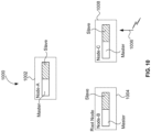
- FIGs. 6-9 illustrate how radar-detection and DFS management is carried out in a wireless repeater network.
- the elements 600 and 601 denote wireless repeater networks.
- the elements 602/608, 606/610 denote Node-A and Node-B, respectively.
- the element 608 denotes a signal transmitted over a communication path 616, such as frequency bands, channels, or other equivalents.
- the element 612 is also a communication path.
- the elements 700 and 701 denote wireless repeater networks.
- the elements 702/708, 706/710 denote Node-A and Node-B, respectively.
- the element 708 denotes a signal transmitted over a communication path 714.
- the elements 800 and 801 denote wireless repeater networks.
- the elements 802/806, 804/808 denote Node-A and Node-B, respectively.
- the elements 806 and 810 denote signals transmitted over communication paths 814, 816, respectively.
- the element 900 denotes a wireless repeater network.
- the elements 902, 904 denote Node-A and Node-B, respectively.
- the element 906 denotes a communication path.
- Node-B 606 which is a UR, detects radar 604, it sends radar-detected and CSA messages to Node-A 606, which does not detect radar. 608. Then, Node-A switches to an available channel. 614. Then, Node-A 608 and Node-B 610 are operating in the same channel in the wireless repeater network 601.
- FIG. 7 illustrates a wireless repeater network comprising Node-B 706 that detects radar 704 and Node-A 702 that does not detect radar.
- Node-A 702 does not receive radar-detected and CSA messages 708 sent by Node-B 706, it continues to stay in its current channel, which is different from the channel that Node-B 706 is operating in. Accordingly, as shown in the element 701, Node-A 708 and Node-B 710 do not communicate each other. That is, the wireless repeater network 701 loses its connectivity.
- Node-B 804 switches to slave mode and scans for the root-node (Node-A) 802. When it finds the root node 802, it connects to the root node 802 in slave mode. Then, Node-B 804 sends Node-A 802 radar-detected message in an effort to force Node-A 802 to abandon the radar-detected channel. Upon receiving radar-detected message from Node-B 804, Node-A 802 triggers transmission of radar-detected and CSA messages 810. Then, Node-B 808 switches to an available channel designated in the CSA message.
- FIG. 9 further illustrates that Node-B 904 reverts to master mode, and the wireless repeater network 900 is re-established in the available channel 906.
- FIGs. 10-14 illustrate how the network is recovered and re-established in case of asymmetric radar detection during CAC.
- the element 1000 denotes a wireless network.
- the elements 1004, 1008 denote Node-A and Node-B, respectively.
- the element 1006 denotes detecting radar.
- the element 1100 denotes a wireless network.
- the elements 1104, 1106 denote Node-A and Node-B, respectively.
- the element 1108 denotes a communication path.
- the element 1200 denotes a wireless network.
- the elements 1202, 1206, and 1208 denote Node-A, Node-B, and Node-C, respectively.
- the elements 1204 and 1220 denote communication paths and the element 1210 denotes a signal.
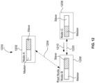
- the element 1300 denotes a wireless network.
- the elements 1302, 1306, and 1308 denote Node-A, Node-B, and Node-C, respectively.
- the elements 1305 and 1330 denote communication paths and the elements 1304, 1310 denote signals.
- the element 1400 denotes a wireless network.
- the elements 1402, 1404, and 1406 denote Node-A, Node-B, and Node-C, respectively.
- the elements 1408, 1410, and 1412 denote communication paths, such as frequency bands, channel, or other equivalents.
- FIG. 10 illustrates that the wireless network 1000 does not have any connection among its nodes 102, 1004, and 1006.
- Node-C 1006 switches to an available channel, while Node-A 1002 and Node-B 1004 are carrying out CAC in another channel.
- the wireless network 1100 does have the complete connectivity among its nodes 1102, 1104, and 1106.
- Node-A 1102 and Node-B 1104 are operating in the same channel, thus they are connected. 1108.
- Node-C 1106 is operating in a different channel.
- Node-C 1208 switches to slave mode after having lost connection with any root node.
- Node-C 1208 scans for a root node. After finding the root-node, Node-B 1206, Node-C 1208 sends radar-detected message 1210 in an effort to force Node-B 1206 to abandon the radar-detected channel.
- FIG. 13 after receiving the radar-detected message from Node-C (1208 in FIG. 12 , 1308 in FIG. 3 ), Node-B 1306 triggers transmission of radar-detected and CSA messages 1304 to Node-C 1308 and Node-A 1302. As illustrated in FIG.
- FIG. 15 shows a flow chart 1500 of an exemplary process where the wireless device performs according to aspects of the disclosure.
- the wireless device is monitoring radars while it is operating in master mode 1502. If it detects radar within its operating frequency channel 1504 and it is not a root node, it may switch to slave mode 1506. Otherwise, it will continue to monitor any radar 1502.
- the wireless device scans frequency channels and tries to find any peer device, which is preferably a root node or a node connecting to the root node 1508. After finding the peer device and establishing a connection with the peer device, the wireless device sends a radar-detected message to the peer device 1510.
- the peer device sends a channel-switch announcement (CSA) message to the wireless device 1512.
- CSA channel-switch announcement
- the wireless device gets to know which channel is radar-free. Accordingly, the wireless device switches the radar-free channel noticed by the peer device 1514. Because the wireless device and the peer device are operating in the same frequency channel after the switching, the communication connection between the two devices may be reestablished 1516. Otherwise, the wireless device has to monitor radar again 1502. After the connection is successfully reestablished, the wireless device may switch back to master mode 1518.
- CSA channel-switch announcement
- nodes in the multi-node network have connections other than their wireless links, which may be on DFS channels, then nodes can utilize those connections for transmission of radar-detected messages and CSA (or ECSA) messages. For example, if two nodes are connected via Ethernet, then a node that detects radar in a certain channel, can inform the other node about the detected radar via the Ethernet link. Thus, if the other node resides in the same channel, it can abandon the radar-detected channel. This is especially important while these nodes are carrying out CAC at the same time.
- CSA or ECSA
- nodes cannot communicate among each other during CAC, due to regulations, when one node detects radar, it can send a CSA message and radar-detected messages over the Ethernet link; thus alerting the other nodes about the presence of radar, and forcing them to switch to an available channel before CAC is completed, and re-establishing the network in the radar-free available channel.
Landscapes
- Engineering & Computer Science (AREA)
- Computer Networks & Wireless Communication (AREA)
- Signal Processing (AREA)
- Quality & Reliability (AREA)
- Databases & Information Systems (AREA)
- Mobile Radio Communication Systems (AREA)
- Radar Systems Or Details Thereof (AREA)
Applications Claiming Priority (3)
| Application Number | Priority Date | Filing Date | Title |
|---|---|---|---|
| US201762454403P | 2017-02-03 | 2017-02-03 | |
| PCT/IB2018/000172 WO2018142224A1 (en) | 2017-02-03 | 2018-02-05 | Methods for dfs and radar-avoidance management in multi-node networks |
| EP18715954.6A EP3577933B1 (de) | 2017-02-03 | 2018-02-05 | Verfahren zur dfs- und radarvermeidungsverwaltung in mehrknotennetzwerken |
Related Parent Applications (1)
| Application Number | Title | Priority Date | Filing Date |
|---|---|---|---|
| EP18715954.6A Division EP3577933B1 (de) | 2017-02-03 | 2018-02-05 | Verfahren zur dfs- und radarvermeidungsverwaltung in mehrknotennetzwerken |
Publications (2)
| Publication Number | Publication Date |
|---|---|
| EP4432774A2 true EP4432774A2 (de) | 2024-09-18 |
| EP4432774A3 EP4432774A3 (de) | 2024-11-13 |
Family
ID=61906782
Family Applications (2)
| Application Number | Title | Priority Date | Filing Date |
|---|---|---|---|
| EP24191773.1A Pending EP4432774A3 (de) | 2017-02-03 | 2018-02-05 | Verfahren für dfs und radarvermeidungsverwaltung in mehrknotennetzwerken |
| EP18715954.6A Active EP3577933B1 (de) | 2017-02-03 | 2018-02-05 | Verfahren zur dfs- und radarvermeidungsverwaltung in mehrknotennetzwerken |
Family Applications After (1)
| Application Number | Title | Priority Date | Filing Date |
|---|---|---|---|
| EP18715954.6A Active EP3577933B1 (de) | 2017-02-03 | 2018-02-05 | Verfahren zur dfs- und radarvermeidungsverwaltung in mehrknotennetzwerken |
Country Status (4)
| Country | Link |
|---|---|
| US (4) | US11006279B2 (de) |
| EP (2) | EP4432774A3 (de) |
| CN (2) | CN110710245B (de) |
| WO (1) | WO2018142224A1 (de) |
Families Citing this family (15)
| Publication number | Priority date | Publication date | Assignee | Title |
|---|---|---|---|---|
| EP4432774A3 (de) * | 2017-02-03 | 2024-11-13 | Airties SAS | Verfahren für dfs und radarvermeidungsverwaltung in mehrknotennetzwerken |
| US10893447B2 (en) * | 2018-01-18 | 2021-01-12 | Cable Television Laboratories, Inc. | Systems and methods for improved Wi-Fi coexistence with radar |
| US10743226B2 (en) * | 2018-02-08 | 2020-08-11 | Cisco Technology, Inc. | Radar shield client assurance in wireless networks |
| CN110896356B (zh) * | 2018-09-12 | 2021-02-02 | 宁德时代新能源科技股份有限公司 | 电池管理系统及系统中的通信方法 |
| CN110896543B (zh) * | 2018-09-12 | 2021-01-12 | 宁德时代新能源科技股份有限公司 | 电池管理系统及传输信息的方法和装置 |
| US10750372B2 (en) * | 2018-12-20 | 2020-08-18 | Cypress Semiconductor Corporation | Operation of access points and autonomous group owners |
| US12028796B2 (en) * | 2019-03-12 | 2024-07-02 | Cypress Semiconductor Corporation | GPS-assisted collaborative and signaling-aided WLAN DFS operation |
| WO2021077324A1 (zh) * | 2019-10-23 | 2021-04-29 | 华为技术有限公司 | 一种数据传输方法以及相关设备 |
| CN113472477B (zh) * | 2020-03-31 | 2023-03-28 | 华为技术有限公司 | 无线通信系统及方法 |
| US11405791B2 (en) * | 2020-06-25 | 2022-08-02 | Hewlett Packard Enterprise Development Lp | System and method for optimizing a channel switch mechanism between DFS channels |
| CN112105070B (zh) * | 2020-08-31 | 2022-05-27 | 新华三技术有限公司 | 一种信道切换方法及装置 |
| CN116209020A (zh) * | 2021-12-01 | 2023-06-02 | 瑞昱半导体股份有限公司 | 网状网络中的接入点及其操作方法 |
| CN114466458A (zh) * | 2022-02-18 | 2022-05-10 | 深圳市联洲国际技术有限公司 | 实现动态频率选择的方法与装置 |
| CN118215091A (zh) * | 2022-12-16 | 2024-06-18 | 华为技术有限公司 | 一种信道切换方法和装置 |
| CN116709273B (zh) * | 2022-12-28 | 2024-04-05 | 荣耀终端有限公司 | 无线通信系统、方法及设备 |
Citations (1)
| Publication number | Priority date | Publication date | Assignee | Title |
|---|---|---|---|---|
| US20130194944A1 (en) | 2012-01-27 | 2013-08-01 | Eren Soyak | System and Method To Avoid Interference With Radar Systems |
Family Cites Families (18)
| Publication number | Priority date | Publication date | Assignee | Title |
|---|---|---|---|---|
| US20050215266A1 (en) * | 2004-03-26 | 2005-09-29 | Intel Corporation | Wireless network dynamic frequency selection |
| US8223715B2 (en) * | 2006-08-11 | 2012-07-17 | Polycom, Inc. | Handoff method in a wireless LAN in the presence of a radar signal |
| US8654782B2 (en) * | 2007-11-05 | 2014-02-18 | Cisco Technology, Inc. | Mesh tree formation in wireless networks |
| US8040791B2 (en) | 2008-02-13 | 2011-10-18 | Cisco Technology, Inc. | Coordinated channel change in mesh networks |
| EP2842381B1 (de) | 2012-04-23 | 2017-09-06 | Intel Corporation | Systeme und verfahren zur interferenzunterdrückung für eine peer-to-peer-netzwerkverbindung |
| TW201509215A (zh) * | 2013-07-22 | 2015-03-01 | Nec Corp | 分享器、無線通信方法及程式 |
| US20170142728A1 (en) * | 2015-08-04 | 2017-05-18 | Network Performance Research Group Llc | Multiple detector coordination for monitoring of multiple channels in the dynamic frequency selection band |
| US20170123049A1 (en) * | 2015-08-04 | 2017-05-04 | Network Performance Research Group Llc | Methods and apparatuses for use of simultaneous multiple channels in the dynamic frequency selection band in wireless networks |
| US10104665B2 (en) * | 2015-08-10 | 2018-10-16 | Network Performance Research Group Llc | Method and apparatus for providing dynamic frequency selection spectrum access in peer-to-peer wireless networks |
| US9439197B1 (en) * | 2015-08-10 | 2016-09-06 | Planetary Network Technologies, Inc. | Method and apparatus for directed adaptive control of dynamic channel selection in wireless networks |
| EP3342238B1 (de) * | 2015-08-26 | 2023-05-31 | Panasonic Intellectual Property Corporation of America | Verbessertes direktzugriffsverfahren für unlizenzierte zellen |
| US10368247B2 (en) * | 2015-11-25 | 2019-07-30 | Network Performance Research Group Llc | Cloud DFS super master detector location systems and methods |
| US10573144B2 (en) * | 2016-10-10 | 2020-02-25 | Netgear, Inc. | Changing topology in a wireless network |
| US9838882B1 (en) * | 2016-10-25 | 2017-12-05 | Cisco Technology, Inc. | Dynamic frequency selection with discrimination |
| US9736845B1 (en) * | 2017-01-03 | 2017-08-15 | Network Performance Research Group Llc | Over the air signaling of dynamic frequency selection (DFS) operating parameters to client devices |
| US20180199342A1 (en) * | 2017-01-09 | 2018-07-12 | Qualcomm Incorporated | Background scan with dynamic time and frequency switching |
| CN110710162B (zh) | 2017-01-20 | 2021-07-06 | 无线通信与技术公司 | 利用通用网关节点设置网状网络的系统和方法 |
| EP4432774A3 (de) * | 2017-02-03 | 2024-11-13 | Airties SAS | Verfahren für dfs und radarvermeidungsverwaltung in mehrknotennetzwerken |
-
2018
- 2018-02-05 EP EP24191773.1A patent/EP4432774A3/de active Pending
- 2018-02-05 US US16/483,567 patent/US11006279B2/en active Active
- 2018-02-05 EP EP18715954.6A patent/EP3577933B1/de active Active
- 2018-02-05 WO PCT/IB2018/000172 patent/WO2018142224A1/en not_active Ceased
- 2018-02-05 CN CN201880021254.8A patent/CN110710245B/zh active Active
- 2018-02-05 CN CN202410053652.5A patent/CN117956478A/zh active Pending
-
2021
- 2021-05-11 US US17/317,516 patent/US11678198B2/en active Active
-
2023
- 2023-06-12 US US18/333,309 patent/US12323816B2/en active Active
-
2025
- 2025-06-02 US US19/225,735 patent/US20250358631A1/en active Pending
Patent Citations (1)
| Publication number | Priority date | Publication date | Assignee | Title |
|---|---|---|---|---|
| US20130194944A1 (en) | 2012-01-27 | 2013-08-01 | Eren Soyak | System and Method To Avoid Interference With Radar Systems |
Also Published As
| Publication number | Publication date |
|---|---|
| EP3577933A1 (de) | 2019-12-11 |
| EP3577933B1 (de) | 2024-07-31 |
| CN117956478A (zh) | 2024-04-30 |
| US11006279B2 (en) | 2021-05-11 |
| CN110710245A (zh) | 2020-01-17 |
| WO2018142224A1 (en) | 2018-08-09 |
| US20200015091A1 (en) | 2020-01-09 |
| US20210266756A1 (en) | 2021-08-26 |
| US11678198B2 (en) | 2023-06-13 |
| US12323816B2 (en) | 2025-06-03 |
| EP4432774A3 (de) | 2024-11-13 |
| CN110710245B (zh) | 2024-01-30 |
| EP3577933C0 (de) | 2024-07-31 |
| US20230403566A1 (en) | 2023-12-14 |
| US20250358631A1 (en) | 2025-11-20 |
Similar Documents
| Publication | Publication Date | Title |
|---|---|---|
| US12323816B2 (en) | Device and method for communication of a channel switch announcement | |
| US10681698B2 (en) | Dedicated backhaul for whole home coverage | |
| CA2532650C (en) | Method and system for delivery of assistance data | |
| EP3165049B1 (de) | Verfahren und vorrichtungen zur bereitstellung von systeminformationen eines zellularen kommunikationsnetzwerks | |
| US10368381B2 (en) | Method for terminal to establish multi-links in wireless communication system, and apparatus therefor | |
| KR101081661B1 (ko) | 2개의 네트워크 상에서 통신 장치를 동작시키기 위한 장치및 방법 | |
| EP2916578B1 (de) | Verfahren, vorrichtung und system zur herstellung einer virtuellen basisstation und zur datenübertragung | |
| EP3442262B1 (de) | Verbessertes offload einer makro-basisstation | |
| EP3297331A1 (de) | Drahtloskommunikationssystem | |
| US9967233B2 (en) | Wireless local area network access points | |
| US12232192B2 (en) | Base station apparatus, terminal apparatus, and control methods for the same for cellular communication network in which relay communication is performed | |
| EP3777325B1 (de) | Verfahren und vorrichtung zur relaisentdeckung | |
| JP7849387B2 (ja) | 中継ユーザ機器(ue)無線リソース制御(rrc)接続状態インジケータ | |
| CN116325598B (zh) | 经由侧链路连接作为中继进行操作的用户装备 | |
| WO2023087907A1 (zh) | 侧行链路的切换方法、装置、终端、存储介质及程序产品 | |
| EP1636944B1 (de) | Verfahren und anordnung zur verringerung der mittleren zeit, die eine kommunikationseinheit zum verbinden mit einem kommunikationsnetzwerk benötigt | |
| US11632716B2 (en) | Wireless communication method used in wireless communication device and wireless communication device | |
| JP6476526B2 (ja) | 無線基地局 | |
| CN116233942A (zh) | 单频段无线接入点的对等辅助带外发现 | |
| EP4271044B1 (de) | Kommunikationsvorrichtung, basisstation, steuerungsverfahren und programm | |
| JP2026500132A (ja) | U2u中継再選択 |
Legal Events
| Date | Code | Title | Description |
|---|---|---|---|
| PUAI | Public reference made under article 153(3) epc to a published international application that has entered the european phase |
Free format text: ORIGINAL CODE: 0009012 |
|
| STAA | Information on the status of an ep patent application or granted ep patent |
Free format text: STATUS: REQUEST FOR EXAMINATION WAS MADE |
|
| 17P | Request for examination filed |
Effective date: 20240730 |
|
| AC | Divisional application: reference to earlier application |
Ref document number: 3577933 Country of ref document: EP Kind code of ref document: P |
|
| AK | Designated contracting states |
Kind code of ref document: A2 Designated state(s): AL AT BE BG CH CY CZ DE DK EE ES FI FR GB GR HR HU IE IS IT LI LT LU LV MC MK MT NL NO PL PT RO RS SE SI SK SM TR |
|
| REG | Reference to a national code |
Ref country code: DE Ref legal event code: R079 Free format text: PREVIOUS MAIN CLASS: H04W0084200000 Ipc: H04W0016140000 |
|
| PUAL | Search report despatched |
Free format text: ORIGINAL CODE: 0009013 |
|
| AK | Designated contracting states |
Kind code of ref document: A3 Designated state(s): AL AT BE BG CH CY CZ DE DK EE ES FI FR GB GR HR HU IE IS IT LI LT LU LV MC MK MT NL NO PL PT RO RS SE SI SK SM TR |
|
| RIC1 | Information provided on ipc code assigned before grant |
Ipc: H04W 92/20 20090101ALN20241009BHEP Ipc: H04W 8/00 20090101ALN20241009BHEP Ipc: H04W 72/541 20230101ALI20241009BHEP Ipc: H04W 72/0453 20230101ALI20241009BHEP Ipc: H04W 16/14 20090101AFI20241009BHEP Ipc: H04W 84/20 20090101ALN20241009BHEP |