EP4432531A1 - Linear motor and machine tool - Google Patents
Linear motor and machine tool Download PDFInfo
- Publication number
- EP4432531A1 EP4432531A1 EP23772398.6A EP23772398A EP4432531A1 EP 4432531 A1 EP4432531 A1 EP 4432531A1 EP 23772398 A EP23772398 A EP 23772398A EP 4432531 A1 EP4432531 A1 EP 4432531A1
- Authority
- EP
- European Patent Office
- Prior art keywords
- linear motor
- slider
- cooling pipe
- axis direction
- end portions
- Prior art date
- Legal status (The legal status is an assumption and is not a legal conclusion. Google has not performed a legal analysis and makes no representation as to the accuracy of the status listed.)
- Granted
Links
Images







Classifications
-
- H—ELECTRICITY
- H02—GENERATION; CONVERSION OR DISTRIBUTION OF ELECTRIC POWER
- H02K—DYNAMO-ELECTRIC MACHINES
- H02K41/00—Propulsion systems in which a rigid body is moved along a path due to dynamo-electric interaction between the body and a magnetic field travelling along the path
- H02K41/02—Linear motors; Sectional motors
- H02K41/03—Synchronous motors; Motors moving step by step; Reluctance motors
- H02K41/031—Synchronous motors; Motors moving step by step; Reluctance motors of the permanent magnet type
-
- H—ELECTRICITY
- H02—GENERATION; CONVERSION OR DISTRIBUTION OF ELECTRIC POWER
- H02K—DYNAMO-ELECTRIC MACHINES
- H02K9/00—Arrangements for cooling or ventilating
- H02K9/19—Arrangements for cooling or ventilating for machines with closed casing and closed-circuit cooling using a liquid cooling medium, e.g. oil
- H02K9/193—Arrangements for cooling or ventilating for machines with closed casing and closed-circuit cooling using a liquid cooling medium, e.g. oil with provision for replenishing the cooling medium; with means for preventing leakage of the cooling medium
-
- H—ELECTRICITY
- H02—GENERATION; CONVERSION OR DISTRIBUTION OF ELECTRIC POWER
- H02K—DYNAMO-ELECTRIC MACHINES
- H02K41/00—Propulsion systems in which a rigid body is moved along a path due to dynamo-electric interaction between the body and a magnetic field travelling along the path
- H02K41/02—Linear motors; Sectional motors
-
- H—ELECTRICITY
- H02—GENERATION; CONVERSION OR DISTRIBUTION OF ELECTRIC POWER
- H02K—DYNAMO-ELECTRIC MACHINES
- H02K41/00—Propulsion systems in which a rigid body is moved along a path due to dynamo-electric interaction between the body and a magnetic field travelling along the path
- H02K41/02—Linear motors; Sectional motors
- H02K41/03—Synchronous motors; Motors moving step by step; Reluctance motors
-
- H—ELECTRICITY
- H02—GENERATION; CONVERSION OR DISTRIBUTION OF ELECTRIC POWER
- H02K—DYNAMO-ELECTRIC MACHINES
- H02K7/00—Arrangements for handling mechanical energy structurally associated with dynamo-electric machines, e.g. structural association with mechanical driving motors or auxiliary dynamo-electric machines
- H02K7/14—Structural association with mechanical loads, e.g. with hand-held machine tools or fans
-
- H—ELECTRICITY
- H02—GENERATION; CONVERSION OR DISTRIBUTION OF ELECTRIC POWER
- H02K—DYNAMO-ELECTRIC MACHINES
- H02K9/00—Arrangements for cooling or ventilating
- H02K9/19—Arrangements for cooling or ventilating for machines with closed casing and closed-circuit cooling using a liquid cooling medium, e.g. oil
Definitions
- the present disclosure relates to a linear motor and a machine tool.
- JP 2014-042423A discloses an invention related to a linear motor.
- This linear motor includes a magnetic field unit that functions as a stator and an armature that functions as a mover.
- the armature has a core, coils, and a cooling pipe.
- the armature generates driving force associated with electromagnetic induction by application of current to the coils, and moves over the magnetic field unit.
- the core is the member that forms the main body of the armature. Housing holes that penetrate in the widthwise direction are formed inside the core.
- the cooling pipe is routed so as to wind back and forth through the housing holes. As a result, the cooling pipe protrudes from the core in the widthwise direction.
- Patent Document 1 JP 2014-042423A
- a linear motor for use in a machine tool.
- the linear motor comprises a magnet plate including a plurality of magnets arranged side by side in a first direction, a slider including a plurality of coils arranged side by side in the first direction, and configured to slide in the first direction relative to the magnet plate, and a cooling pipe provided at a surface portion of the slider on a side opposite to a side facing the magnet plate.
- the surface portion is provided with a plurality of grooves and a plurality of ridges that alternate in the first direction.
- the grooves are each elongated in a second direction that is parallel to a surface of the magnet plate and orthogonal to the first direction.
- the ridges are each elongated in the second direction.
- the cooling pipe is routed on the slider so as to wind back and forth through the grooves.
- Each of the ridges has two end portions in the second direction including a first end portion on a side along which a bent portion of the cooling pipe extends, and on at least one side in the second direction, each of the first end portions is entirely located inward of two end faces of the slider in the second direction, or a portion of each of the first end portions, excluding a central portion of the first end portion in the first direction, is located inward of the two end faces of the slider in the second direction.
- each of the first end portions is entirely located inward of the two end faces of the slider in the second direction, or a portion of each of the first end portions, excluding the central portion of the first end portion in the first direction, is located inward of the two end faces of the slider in the second direction.
- the two end portions of each of the ridges further include a second end portion on a side along which a bent portion of the cooling pipe does not extend, and the second end portions are each located at the same position as one of the two end faces when viewed in a third direction orthogonal to both the first direction and the second direction.
- bent portions of the cooling pipe are located outward of the two end faces when viewed in a third direction orthogonal to both the first direction and the second direction.
- end portions of the cooling pipe in the second direction overlap end portions of the coil in the second direction when viewed in a third direction orthogonal to both the first direction and the second direction.
- a width of the cooling pipe in the second direction is longer than a width of each of the coils in the second direction.
- a machine tool comprising the linear motor, and a spindle configured to rotatably hold a workpiece or a tool.
- the linear motor is used to move a position of the spindle.
- the machine tool comprises the linear motor, and a table on which a workpiece is placeable.
- the linear motor is used to drive the table.
- a machine tool comprising the linear motor, and a loader configured to transport a member.
- the linear motor is used to drive the loader.
- FIG. 1 is an oblique perspective view of the linear motor 100 according to this embodiment.
- the linear motor 100 includes a magnet plate 10 and a slider 50.
- the magnet plate 10 functions as a stator.
- a plurality of magnets 12 are arranged side by side on the magnet plate 10.
- the direction in which the magnets 12 are next to each other will hereinafter also be referred to as the X-axis direction (first direction).
- the direction parallel to the surface of the magnet plate 10 and orthogonal to the X-axis direction will also be referred to as the Y-axis direction (second direction).
- the direction orthogonal to both the X-axis direction and the Y-axis direction will also be referred to as the Z-axis direction (third direction).
- the magnets 12 are spaced apart by a predetermined gap in the X-axis direction on the magnet plate 10.
- the magnets 12 are each a permanent magnet.
- the magnets 12 are provided on the magnet plate 10 such that the polarities of adjacent magnets 12 are opposite to each other. For example, assume that the top surface of one magnet 12 is the N pole and the bottom surface of that one magnet 12 is the S pole. In this case, the magnet 12 arranged adjacent to the one magnet 12 has an S pole on the top surface and an N pole on the bottom surface.
- the slider 50 functions as a mover.
- the slider 50 includes a plurality of coils 52.
- the coils 52 are provided side by side in the X-axis direction in the slider 50.
- the coils 52 are wound in an oval shape around later-described teeth 53 (see FIG. 3 ) formed in the slider 50.
- the coils 52 are provided in the slider 50 so as to face the magnets 12. In other words, the coils 52 are provided in the slider 50 so as to overlap the magnets 12 when viewed in the Z-axis direction.
- the slider 50 When a magnetic field, which is generated by applying alternating current to the coils 52, acts on the magnets 12, the slider 50 receives thrust and slides in the X-axis direction over the magnet plate 10.
- the alternating current is supplied by a power supply (not shown) that is electrically connected to the coils 52, for example.
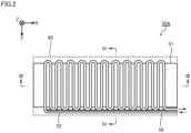
- FIG. 2 is a diagram illustrating the slider 50 from the Z-axis direction.
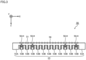
- FIG. 3 is a cross-sectional view of the slider 50 taken along line III-III shown in FIG. 2 .
- FIG. 4 is a cross-sectional view of the slider 50 taken along line IV-IV shown in FIG. 2 .
- the slider 50 includes a housing 60 that gives it its appearance.
- the housing 60 is made of resin, for example.
- a slider core 51, the coils 52, a cooling pipe 56, and fixing members 58 are housed in the housing 60.
- the slider core 51 is constituted by an electromagnetic steel plate, for example. Teeth 53 are formed on the slider core 51.
- the teeth 53 protrude from the lower surface of the slider core 51 (i.e., the surface portion on the side facing the magnet plate 10) toward the magnet plate 10.
- the teeth 53 are formed on the slider core 51 so as to face the above-described magnet plate 10 and overlap the magnet plate 10 when viewed in the Z-axis direction.
- the teeth 53 are each elongated in the Y-axis direction.
- the teeth 53 include auxiliary teeth 53A that are located most outward in the X-axis direction and do not have coils 52 wrapped thereon, and coil teeth 53B that are located inward of the auxiliary teeth 53A in the X-axis direction and have coils 52 wrapped thereon.
- the coils 52 are wound in an oval shape around the coil teeth 53B.
- Through holes H elongated in the Y-axis direction are formed in some of the coil teeth 53B.
- the fixing members 58 are respectively inserted into the through holes H.
- a threaded hole extending in the Z-axis direction is formed in each of the fixing members 58, and the through holes H in the slider core 51 are formed so as to be in communication with the threaded holes of the fixing members 58 in the Z-axis direction.
- the fixing members 58 may have any shape.
- the fixing members 58 may be shaped as a cuboid rectangular bar, a circular column, or any other shape.
- the fixing members 58 are constituted by a different type of member from the slider core 51.
- the slider core 51 is constituted by a laminated steel plate, and the fixing members 58 are formed using a metal other than the metal forming the laminated steel plate.
- the fixing members 58 may be made of iron, or may be made of another type of metal.
- the cooling pipe 56 is provided on the side opposite to the side that faces the magnet plate 10.
- the cooling pipe 56 has a coolant inlet and a coolant outlet.
- the inlet and the outlet are connected to a cooler (not shown).
- the coolant flows from the inlet of the cooling pipe 56 to the outlet of the cooling pipe 56 and cools the slider 50.
- the coolant is sent to the cooler and cooled.
- the cooled coolant is sent to the inlet of the cooling pipe 56 again.
- the coolant circulates along the upper surface of the slider core 51 and absorbs heat from the slider 50.
- the coolant is a liquid including water or the like.
- the cooling pipe 56 is constituted by a metal pipe that has good thermal conductivity, for example.
- the cooling pipe 56 may be made of a copper pipe, an aluminum pipe, or a stainless steel pipe.
- FIG. 3 illustrates an example in which the cooling pipe 56 has a circular cross-sectional shape
- the cooling pipe 56 may have any cross-sectional shape.
- the cooling pipe 56 may have a polygonal cross-sectional shape, for example, or any other cross-sectional shape.
- FIG. 5 is a diagram illustrating the slider core 51 from the Z-axis direction.
- FIG. 6 is a cross-sectional view of the slider core 51 taken along line VI-VI shown in FIG. 5 .
- FIG. 7 is a cross-sectional view of the slider core 51 taken along line VII-VII shown in FIG. 5 .
- the surface portion of the slider core 51 on the side opposite to the side facing the magnet plate 10 is provided with grooves G and ridges R that alternate in the X-axis direction.
- the grooves G are formed at regular intervals in the X-axis direction.
- the grooves G are elongated in the Y-axis direction.
- the cooling pipe 56 described above is routed so as to wind back and forth through the grooves G.
- the length of each groove G in the Y-axis direction is the same as the length of the slider core 51 in the Y-axis direction. In other words, when viewed in the Z-axis direction, the two end portions of each groove G in the Y-axis direction are at the same positions as the two end faces of the slider core 51 in the Y-axis direction.
- FIG. 7 shows an example in which the grooves G have a semicircular cross-sectional shape
- the grooves G may have any cross-sectional shape.
- the cross-sectional shape may be polygonal or another shape.
- the ridges R are formed at regular intervals in the X-axis direction.
- the ridges R are elongated in the Y-axis direction. Furthermore, the ridges R protrude from the slider core 51 toward the side opposite to the side facing the magnet plate 10.
- Each of the grooves G is formed by two adjacent ridges R.
- the end portion along which a bent portion of the cooling pipe 56 extends will also be referred to as an "end portion E1".
- the bent portions of the cooling pipe 56 are each a U-shaped portion that is bent from one side to the other side in the Y-axis direction.
- the end portion on the side along which a bent portion of the cooling pipe 56 does not extend will be referred to as an "end portion E2". Since the cooling pipe 56 winds back and forth along the grooves G, the end portions E1 and E2 alternatingly appear in the X-axis direction.
- the end portions E1 of the ridges R are located inward of the two end faces of the slider 50 in the Y-axis direction.
- the end portions E1 are located at a distance ⁇ D away from the end faces of the slider 50. Accordingly, the bent portions of the cooling pipe 56 can be routed at more inward positions on the slider core 51. As a result, the width of the cooling pipe 56 in the Y-axis direction is reduced, and the size of the linear motor 100 in the Y-axis direction is reduced.
- FIG. 8 is a diagram in which the cooling pipe 56 has been provided on the slider core 51 shown in FIGS. 5 to 7 .
- FIG. 9 is a diagram in which the cooling pipe 56 has been provided on a slider core 51X according to a comparative example.
- the bent portions of the cooling pipe 56 can be routed at more inward positions on the slider core 51.
- the width of the linear motor 100 in the Y-axis direction is " ⁇ Y1".
- the bent portions of the cooling pipe 56 protrude a larger amount from the two end faces of the slider core 51X in the Y-axis direction.
- the size of the linear motor 100 in the Y-axis direction is " ⁇ Y0".
- the width " ⁇ Y0" shown in FIG. 9 is larger than the width " ⁇ Y1" shown in FIG. 8 .
- the end portions E2 of the ridges R on the side along which the bent portions of the cooling pipe 56 do not extend may be shaved down or may not be shaved down.
- the end portions E2 are not shaved down.
- the end portions E2 of the ridges R are at the same position as one of the end faces of the slider core 51 in the Y-axis direction when viewed in the X-axis direction.
- the end portions E2 are coplanar with the end face of the slider core 51 in the Y-axis direction.
- the cooling pipe 56 is routed such that the bent portions are positioned outward of the two end faces of the slider core 51 in the Y-axis direction.
- the bent portions of the cooling pipe 56 are routed so as to protrude from the slider core 51 in the Y-axis direction.
- the cooling pipe 56 is arranged such that the outer peripheral surfaces of the bent portions are located outward of the end faces, and the inner peripheral surfaces of the bent portions are located inward of the end faces.
- the coils 52 are provided such that the end portions thereof are located outward of the two end faces of the slider core 51 in the Y-axis direction.
- the coils 52 are provided on the slider core 51 so as to protrude from the slider core 51 in the Y-axis direction.
- the end portions of the cooling pipe 56 in the Y-axis direction i.e., the bent portions
- FIG. 10 is a diagram illustrating a slider core 51A according to Variation 1 from the Z-axis direction.
- the end portions E1 of the ridges R shown in FIG. 5 are located inward of the end faces of the slider core 51A on both sides in the Y-axis direction.
- the end portions E1 are located inward of the end faces of the slider core 51A only on one side in the Y-axis direction.
- bent portions on one side of the cooling pipe 56 can be routed further inward relative to the slider core 51, and the size of the linear motor 100 in the Y-axis direction can be reduced.
- FIG. 11 is a diagram illustrating a slider core 51B according to Variation 2 from the Z-axis direction.
- the end portions E2 on the side along which the bent portions of the cooling pipe 56 do not extend are not shaved down.
- the end portions E2 of the ridges R are shaved down.
- the end portions E2 of the ridges R are located inward of both end faces of the slider 50 in the Y-axis direction. It is preferable that the distance ⁇ D from the end face of the slider core 51B to each of the end portions E2 is equivalent to the distance ⁇ D from the end face of the slider core 51B to each of the end portions E1. Accordingly, the shape of the slider core 51B is substantially symmetrical with respect to the X-axis. As a result, the operation of linear motor 100 is stabilized.
- FIG. 12 is a diagram illustrating a slider core 51C according to Variation 3 from the Z-axis direction.
- the end portions E1 of the ridges R shown in FIG. 5 described above are entirely located inward of the two end faces of the slider core 51 in the Y-axis direction.
- the slider core 51C according to the present variation only a portion of each of the end portions E1 in the X-axis direction is located inward of the two end faces.
- the central portion of the end portion E1 in the X-axis direction is at the same position as the end face of the slider core 51 in the Y-axis direction when viewed in the Z-axis direction.
- the central portion is coplanar with the end face of the slider core 51 in the Y-axis direction.
- the remaining portion of the end portion E1 other the central portion is located inward of the two end faces of the slider core 51 in the Y-axis direction.
- each of the end portions E1 is R-chamfered such that the outer peripheral surface extends along the inner peripheral surface of the corresponding bent portion of the cooling pipe 56.
- the chamfering method for the end portions E1 is not limited to R chamfering, and other chamfering methods may be employed.
- the end portions E1 may be C-chamfered.
- the chamfered end portions E1 may be entirely located inward of the two end faces of the slider core 51 in the Y-axis direction.
- the end portions E1 of the ridges R are shaved down by the distance ⁇ D (see FIG. 5 ) from the two end faces of the slider 50 in the Y-axis direction so as to be located inward of the end faces.
- ⁇ D the distance ⁇ D
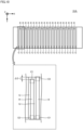
- FIG. 13 is a diagram illustrating the above-described cooling pipe 56 from the Z-axis direction.
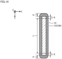
- FIG. 14 is a diagram illustrating a coil 52 wound around a tooth 53 from the Z-axis direction.
- S denotes the length of the straight portion of the cooling pipe 56 in the Y-axis direction.
- X denotes the length of the portions of the cooling pipe 56 other than the straight portion. In this case, the total length of the cooling pipe 56 in the Y-axis direction is "S+X".
- L denotes the length of the slider core 51 in the Y-axis direction is.
- L corresponds to the laminated thickness of the slider core 51.
- E denotes the distance of separation between the tooth 53 and the coil 52 in the Y-axis direction.
- L denotes the length of the slider core 51 in the Y-axis direction.
- A denotes the width of the end portion of the coil 52 in the Y-axis direction.
- the width of the cooling pipe 56 in the Y-axis direction is longer than the width of the coil 52 in the Y-axis direction. For this reason, it is preferable that the total length "S+X" of the cooling pipe 56 in the Y-axis direction satisfies the following Expression 1. S + X ⁇ L + 2 A + E
- the width of the cooling pipe 56 in the Y-axis direction is longer than the width of each of the coils 52 in the Y-axis direction. Also, the cooling pipe 56 is shorter by the distance ⁇ D in the Y-axis direction. As a result, the size of the linear motor 100 in the Y-axis direction is reduced while also maintaining the ability of the cooling pipe 56 to cool the coil 52.
- the linear motor 100 can be used to drive various parts in a machine tool, for example.
- the term "machine tool” as used herein is a concept that includes various devices that have the function of machining a workpiece.
- the machine tool 200 may be a horizontal machining center or a vertical machining center.
- the machine tool 200 may be a lathe, an additive processing machine, or another cutting or grinding machine.
- the magnet plate 10 which functions as a stator
- the slider 50 which functions as a mover
- the part to be driven is fixed to the slider 50.
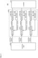
- FIG. 15 is a diagram illustrating an example of the configuration of a machine tool 200.
- the linear motor 100 is used to move the position of a spindle 250 for rotatably holding a workpiece or a tool, for example.
- the spindle 250 may be a work spindle for rotating a workpiece, or may be a tool spindle for rotating a tool.
- the machine tool 200 includes a control unit 200A, a drive unit 240A, and the spindle 250.
- the control unit 200A is a CNC (Computer Numerical Control) device, for example.
- the CNC device includes at least one integrated circuit.
- the integrated circuit is at least one CPU (Central Processing Unit), at least one MPU (Micro Processing Unit), at least one ASIC (Application Specific Integrated Circuit), at least one FPGA (Field Programmable Gate Array), or any combination thereof.
- the control unit 200A controls the operation of the drive unit 240A by executing various programs such as a machining program.
- the drive unit 240A is a mechanism for driving the spindle 250.
- the drive unit 240A may have any device configuration.
- the drive unit 240A may be constituted by a single drive unit, or may be constituted by a plurality of drive units.
- the drive unit 240A is constituted by motor drivers 241A to 241C, linear motors 242A to 242C, and encoders 243A to 243C.
- the linear motors 242A to 242C each correspond to the linear motor 100 described above.
- the motor driver 241A controls the driving of the spindle 250 in the X' axis direction.
- the motor driver 241A receives a control signal from the control unit 200A and outputs a current that corresponds to the control signal to the linear motor 242A.
- control unit 200A sequentially outputs control signals that include a target position to the motor driver 241A.
- the motor driver 241A calculates the actual position of the spindle 250 based on a feedback signal from the encoder 243A, and outputs a current that reduces the difference between the actual position and the target position to the linear motor 242A. Accordingly, the motor driver 241A moves the spindle 250 to a desired position in the X' axis direction.
- the motor driver 241B controls the driving of the spindle 250 in the Y' axis direction.
- the motor driver 241B receives a control signal from the control unit 200A and outputs a current that corresponds to the control signal to the linear motor 242B.
- control unit 200A sequentially outputs control signals that include a target position to the motor driver 241B.
- the motor driver 241B calculates the actual position of the spindle 250 based on a feedback signal from the encoder 243B, and outputs a current that reduces the difference between the actual position and the target position to the linear motor 242B. Accordingly, the motor driver 241B moves the spindle 250 to a desired position in the Y' axis direction.
- the motor driver 241C controls the driving of the spindle 250 in the Z' axis direction.
- the motor driver 241C receives a control signal from the control unit 200A and outputs a current that corresponds to the control signal to the linear motor 242C.
- control unit 200A sequentially outputs control signals that include a target position to the motor driver 241C.
- the motor driver 241C calculates the actual position of the spindle 250 based on a feedback signal from the encoder 243C, and outputs a current that reduces the difference between the actual position and the target position to the linear motor 242C. Accordingly, the motor driver 241C moves the spindle 250 to a desired position in the Z' axis direction.
- FIG. 16 is a diagram illustrating another example of the configuration of a machine tool 200.
- the linear motor 100 is used to drive a table 260 provided in a machine tool, for example.
- the table 260 is a stand for placement of a workpiece to be subjected to machining.
- the machine tool 200 includes a control unit 200A, a drive unit 240B, and the table 260.
- the drive unit 240B is a mechanism for driving the table 260.
- the drive unit 240B may have any device configuration.
- the drive unit 240B may be constituted by a single drive unit, or may be constituted by a plurality of drive units.
- the drive unit 240B is constituted by motor drivers 241D, 241E, linear motors 242D, 242E, and encoders 243D, 243E.
- the linear motors 242D, 242E each correspond to the linear motor 100 described above.
- the motor driver 241D controls the driving of the table 260 in the X' axis direction.
- the motor driver 241D receives a control signal from the control unit 200A and outputs a current that corresponds to the control signal to the linear motor 242D.
- control unit 200A sequentially outputs control signals that include a target position to the motor driver 241D.
- the motor driver 241D calculates the actual position of the table 260 based on a feedback signal from the encoder 243D, and outputs a current that reduces the difference between the actual position and the target position to the linear motor 242D. Accordingly, the motor driver 241D moves the table 260 to a desired position in the X' axis direction.
- the motor driver 241E controls the driving of the table 260 in the Y' axis direction.
- the motor driver 241E receives a control signal from the control unit 200A and outputs a current that corresponds to the control signal to the linear motor 242E.
- control unit 200A sequentially outputs control signals that include a target position to the motor driver 241E.
- the motor driver 241E calculates the actual position of the table 260 based on a feedback signal from the encoder 243E, and outputs a current that reduces the difference between the actual position and the target position to the linear motor 242E. Accordingly, the motor driver 241E moves the table 260 to a desired position in the Y' axis direction.
- FIG. 17 is a diagram illustrating another example of the configuration of a machine tool 200.
- the linear motor 100 is used to drive a loader 270 for transporting a member, for example.
- the member may be a workpiece that has not yet been subjected to machining, a machined workpiece, or a tool.
- the machine tool 200 includes a control unit 200A, a drive unit 240C, and the loader 270.
- the drive unit 240C is a mechanism for driving the loader 270.
- the drive unit 240C may have any device configuration.
- the drive unit 240C may be constituted by a single drive unit, or may be constituted by a plurality of drive units.
- the drive unit 240C is constituted by motor drivers 241F, 241G, 241H, linear motors 242F, 242G, 242H, and encoders 243F, 243G, 243H.
- the linear motors 242F, 242G, 242H each correspond to the linear motor 100 described above.
- the motor driver 241F controls the driving of the loader 270 in the X' axis direction.
- the motor driver 241F receives a control signal from the control unit 200A and outputs a current that corresponds to the control signal to the linear motor 242F.
- control unit 200A sequentially outputs control signals that include a target position to the motor driver 241F.
- the motor driver 241F calculates the actual position of the loader 270 based on a feedback signal from the encoder 243F, and outputs a current that reduces the difference between the actual position and the target position to the linear motor 242F. Accordingly, the motor driver 241F moves the loader 270 to a desired position in the X' axis direction.
- the motor driver 241G controls the driving of the loader 270 in the Y' axis direction.
- the motor driver 241G receives a control signal from the control unit 200A and outputs a current that corresponds to the control signal to the linear motor 242G.
- control unit 200A sequentially outputs control signals that include a target position to the motor driver 241G.
- the motor driver 241G calculates the actual position of the loader 270 based on a feedback signal from the encoder 243G, and outputs a current that reduces the difference between the actual position and the target position to the linear motor 242G. Accordingly, the motor driver 241G moves the loader 270 to a desired position in the Y' axis direction.
- the motor driver 241H controls the driving of the loader 270 in the Z' axis direction.
- the motor driver 241H receives a control signal from the control unit 200A and outputs a current that corresponds to the control signal to the linear motor 242H.
- control unit 200A sequentially outputs control signals that include a target position to the motor driver 241H.
- the motor driver 241H calculates the actual position of the loader 270 based on a feedback signal from the encoder 243H, and outputs a current that reduces the difference between the actual position and the target position to the linear motor 242H. Accordingly, the motor driver 241H moves the loader 270 to a desired position in the Z' axis direction.
Landscapes
- Engineering & Computer Science (AREA)
- Power Engineering (AREA)
- Physics & Mathematics (AREA)
- Chemical & Material Sciences (AREA)
- Combustion & Propulsion (AREA)
- Electromagnetism (AREA)
- Linear Motors (AREA)
Abstract
Description
- The present disclosure relates to a linear motor and a machine tool.
-
JP 2014-042423A - The core is the member that forms the main body of the armature. Housing holes that penetrate in the widthwise direction are formed inside the core. The cooling pipe is routed so as to wind back and forth through the housing holes. As a result, the cooling pipe protrudes from the core in the widthwise direction.
- Patent Document 1:
JP 2014-042423A - If the cooling pipe protrudes a large amount from the core in the widthwise direction, the size of the linear motor in the widthwise direction increases. Therefore, a technique for reducing the size of the linear motor in the widthwise direction is desired.
- According to one example of the present disclosure, there is provided a linear motor for use in a machine tool. The linear motor comprises a magnet plate including a plurality of magnets arranged side by side in a first direction, a slider including a plurality of coils arranged side by side in the first direction, and configured to slide in the first direction relative to the magnet plate, and a cooling pipe provided at a surface portion of the slider on a side opposite to a side facing the magnet plate. The surface portion is provided with a plurality of grooves and a plurality of ridges that alternate in the first direction. The grooves are each elongated in a second direction that is parallel to a surface of the magnet plate and orthogonal to the first direction. The ridges are each elongated in the second direction. The cooling pipe is routed on the slider so as to wind back and forth through the grooves. Each of the ridges has two end portions in the second direction including a first end portion on a side along which a bent portion of the cooling pipe extends, and on at least one side in the second direction, each of the first end portions is entirely located inward of two end faces of the slider in the second direction, or a portion of each of the first end portions, excluding a central portion of the first end portion in the first direction, is located inward of the two end faces of the slider in the second direction..
- According to one example of the present disclosure, on both sides in the second direction, each of the first end portions is entirely located inward of the two end faces of the slider in the second direction, or a portion of each of the first end portions, excluding the central portion of the first end portion in the first direction, is located inward of the two end faces of the slider in the second direction.
- According to one example of the present disclosure, the two end portions of each of the ridges further include a second end portion on a side along which a bent portion of the cooling pipe does not extend, and the second end portions are each located at the same position as one of the two end faces when viewed in a third direction orthogonal to both the first direction and the second direction.
- According to one example of the present disclosure, bent portions of the cooling pipe are located outward of the two end faces when viewed in a third direction orthogonal to both the first direction and the second direction.
- According to one example of the present disclosure, end portions of the cooling pipe in the second direction overlap end portions of the coil in the second direction when viewed in a third direction orthogonal to both the first direction and the second direction.
- According to one example of the present disclosure, a width of the cooling pipe in the second direction is longer than a width of each of the coils in the second direction.
- According to another example of the present disclosure, there is provided a machine tool. The machine tool comprises the linear motor, and a spindle configured to rotatably hold a workpiece or a tool. The linear motor is used to move a position of the spindle.
- According to another example of the present disclosure, there is provided a machine tool. the machine tool comprises the linear motor, and a table on which a workpiece is placeable. The linear motor is used to drive the table.
- According to another example of the present disclosure, there is provided a machine tool. The machine tool comprises the linear motor, and a loader configured to transport a member. The linear motor is used to drive the loader.
- These and other objects, features, aspects and advantages of the present invention will become apparent from the following detailed description of the invention, taken in conjunction with the accompanying drawings.
-
-
FIG. 1 is an oblique perspective view of a linear motor according to an embodiment. -
FIG. 2 is a diagram illustrating a slider from the Z-axis direction. -
FIG. 3 is a cross-sectional view of the slider taken along line III-III shown inFIG. 2 . -
FIG. 4 is a cross-sectional view of the slider taken along line IV-IV shown inFIG. 2 . -
FIG. 5 is a diagram illustrating a slider core from the Z-axis direction. -
FIG. 6 is a cross-sectional view of the slider core taken along line VI-VI shown inFIG. 5 . -
FIG. 7 is a cross-sectional view of the slider core taken along line VII-VII shown inFIG. 5 . -
FIG. 8 is a diagram in which a cooling pipe has been provided on the slider core shown inFIGS. 5 to 7 . -
FIG. 9 is a diagram in which a cooling pipe has been provided on a slider core according to a comparative example. -
FIG. 10 is a diagram illustrating a slider core according toVariation 1 from the Z-axis direction. -
FIG. 11 is a diagram illustrating a slider core according to Variation 2 from the Z-axis direction. -
FIG. 12 is a diagram illustrating a slider core according to Variation 3 from the Z-axis direction. -
FIG. 13 is a diagram illustrating the cooling pipe from the Z-axis direction. -
FIG. 14 is a diagram illustrating a coil wound around a tooth from the Z-axis direction. -
FIG. 15 is a diagram illustrating an example of the device configuration of a machine tool. -
FIG. 16 is a diagram illustrating another example of the device configuration of the machine tool. -
FIG. 17 is a diagram illustrating another example of the device configuration of the machine tool. - Hereinafter, each embodiment according to the present invention will be described with reference to the drawings. In the following description, the same parts and constituent elements are denoted by the same reference numerals. Their names and functions are also the same. Therefore, detailed description of these will not be repeated. Note that each embodiment and each modification described below may be selectively combined as appropriate.
- First, an overview of a
linear motor 100 will be described with reference toFIG. 1. FIG. 1 is an oblique perspective view of thelinear motor 100 according to this embodiment. - As shown in
FIG. 1 , thelinear motor 100 includes amagnet plate 10 and aslider 50. - The
magnet plate 10 functions as a stator. A plurality ofmagnets 12 are arranged side by side on themagnet plate 10. For convenience in the description, the direction in which themagnets 12 are next to each other will hereinafter also be referred to as the X-axis direction (first direction). The direction parallel to the surface of themagnet plate 10 and orthogonal to the X-axis direction will also be referred to as the Y-axis direction (second direction). The direction orthogonal to both the X-axis direction and the Y-axis direction will also be referred to as the Z-axis direction (third direction). - The
magnets 12 are spaced apart by a predetermined gap in the X-axis direction on themagnet plate 10. Themagnets 12 are each a permanent magnet. Themagnets 12 are provided on themagnet plate 10 such that the polarities ofadjacent magnets 12 are opposite to each other. For example, assume that the top surface of onemagnet 12 is the N pole and the bottom surface of that onemagnet 12 is the S pole. In this case, themagnet 12 arranged adjacent to the onemagnet 12 has an S pole on the top surface and an N pole on the bottom surface. - The
slider 50 functions as a mover. Theslider 50 includes a plurality ofcoils 52. Thecoils 52 are provided side by side in the X-axis direction in theslider 50. Thecoils 52 are wound in an oval shape around later-described teeth 53 (seeFIG. 3 ) formed in theslider 50. - The
coils 52 are provided in theslider 50 so as to face themagnets 12. In other words, thecoils 52 are provided in theslider 50 so as to overlap themagnets 12 when viewed in the Z-axis direction. - When a magnetic field, which is generated by applying alternating current to the
coils 52, acts on themagnets 12, theslider 50 receives thrust and slides in the X-axis direction over themagnet plate 10. The alternating current is supplied by a power supply (not shown) that is electrically connected to thecoils 52, for example. - Next, the
aforementioned slider 50 will be described in further detail with reference toFIGS. 2 to 4 .FIG. 2 is a diagram illustrating theslider 50 from the Z-axis direction.FIG. 3 is a cross-sectional view of theslider 50 taken along line III-III shown inFIG. 2 .FIG. 4 is a cross-sectional view of theslider 50 taken along line IV-IV shown inFIG. 2 . - The
slider 50 includes ahousing 60 that gives it its appearance. Thehousing 60 is made of resin, for example. Aslider core 51, thecoils 52, a coolingpipe 56, and fixingmembers 58 are housed in thehousing 60. - The
slider core 51 is constituted by an electromagnetic steel plate, for example.Teeth 53 are formed on theslider core 51. - The
teeth 53 protrude from the lower surface of the slider core 51 (i.e., the surface portion on the side facing the magnet plate 10) toward themagnet plate 10. In other words, theteeth 53 are formed on theslider core 51 so as to face the above-describedmagnet plate 10 and overlap themagnet plate 10 when viewed in the Z-axis direction. Moreover, theteeth 53 are each elongated in the Y-axis direction. - The
teeth 53 includeauxiliary teeth 53A that are located most outward in the X-axis direction and do not havecoils 52 wrapped thereon, andcoil teeth 53B that are located inward of theauxiliary teeth 53A in the X-axis direction and havecoils 52 wrapped thereon. Thecoils 52 are wound in an oval shape around thecoil teeth 53B. - Through holes H elongated in the Y-axis direction are formed in some of the
coil teeth 53B. The fixingmembers 58 are respectively inserted into the through holes H. A threaded hole extending in the Z-axis direction is formed in each of the fixingmembers 58, and the through holes H in theslider core 51 are formed so as to be in communication with the threaded holes of the fixingmembers 58 in the Z-axis direction. - The fixing
members 58 may have any shape. For example, the fixingmembers 58 may be shaped as a cuboid rectangular bar, a circular column, or any other shape. - The fixing
members 58 are constituted by a different type of member from theslider core 51. For example, theslider core 51 is constituted by a laminated steel plate, and the fixingmembers 58 are formed using a metal other than the metal forming the laminated steel plate. For example, the fixingmembers 58 may be made of iron, or may be made of another type of metal. - The cooling
pipe 56 is provided on the side opposite to the side that faces themagnet plate 10. The coolingpipe 56 has a coolant inlet and a coolant outlet. The inlet and the outlet are connected to a cooler (not shown). The coolant flows from the inlet of the coolingpipe 56 to the outlet of the coolingpipe 56 and cools theslider 50. Upon reaching the outlet, the coolant is sent to the cooler and cooled. After that, the cooled coolant is sent to the inlet of the coolingpipe 56 again. In this manner, the coolant circulates along the upper surface of theslider core 51 and absorbs heat from theslider 50. As one example, the coolant is a liquid including water or the like. - The cooling
pipe 56 is constituted by a metal pipe that has good thermal conductivity, for example. For example, the coolingpipe 56 may be made of a copper pipe, an aluminum pipe, or a stainless steel pipe. - Note that although
FIG. 3 illustrates an example in which thecooling pipe 56 has a circular cross-sectional shape, the coolingpipe 56 may have any cross-sectional shape. The coolingpipe 56 may have a polygonal cross-sectional shape, for example, or any other cross-sectional shape. - Next, the
aforementioned slider core 51 will be described in further detail with reference toFIGS. 5 to 9 .FIG. 5 is a diagram illustrating theslider core 51 from the Z-axis direction.FIG. 6 is a cross-sectional view of theslider core 51 taken along line VI-VI shown inFIG. 5 .FIG. 7 is a cross-sectional view of theslider core 51 taken along line VII-VII shown inFIG. 5 . - The surface portion of the
slider core 51 on the side opposite to the side facing themagnet plate 10 is provided with grooves G and ridges R that alternate in the X-axis direction. - The grooves G are formed at regular intervals in the X-axis direction. The grooves G are elongated in the Y-axis direction. The cooling
pipe 56 described above is routed so as to wind back and forth through the grooves G. The length of each groove G in the Y-axis direction is the same as the length of theslider core 51 in the Y-axis direction. In other words, when viewed in the Z-axis direction, the two end portions of each groove G in the Y-axis direction are at the same positions as the two end faces of theslider core 51 in the Y-axis direction. - Note that although
FIG. 7 shows an example in which the grooves G have a semicircular cross-sectional shape, the grooves G may have any cross-sectional shape. For example, the cross-sectional shape may be polygonal or another shape. - The ridges R are formed at regular intervals in the X-axis direction. The ridges R are elongated in the Y-axis direction. Furthermore, the ridges R protrude from the
slider core 51 toward the side opposite to the side facing themagnet plate 10. Each of the grooves G is formed by two adjacent ridges R. - In the following description, out of the two end portions of each of the ridges R in the Y-axis direction, the end portion along which a bent portion of the cooling
pipe 56 extends will also be referred to as an "end portion E1". The bent portions of the coolingpipe 56 are each a U-shaped portion that is bent from one side to the other side in the Y-axis direction. Also, out of the two end portions of each of the ridges R in the Y-axis direction, the end portion on the side along which a bent portion of the coolingpipe 56 does not extend will be referred to as an "end portion E2". Since the coolingpipe 56 winds back and forth along the grooves G, the end portions E1 and E2 alternatingly appear in the X-axis direction. - In the present embodiment, the end portions E1 of the ridges R are located inward of the two end faces of the
slider 50 in the Y-axis direction. In the example illustrated inFIG. 5 , the end portions E1 are located at a distance ΔD away from the end faces of theslider 50. Accordingly, the bent portions of the coolingpipe 56 can be routed at more inward positions on theslider core 51. As a result, the width of the coolingpipe 56 in the Y-axis direction is reduced, and the size of thelinear motor 100 in the Y-axis direction is reduced. -
FIG. 8 is a diagram in which thecooling pipe 56 has been provided on theslider core 51 shown inFIGS. 5 to 7 .FIG. 9 is a diagram in which thecooling pipe 56 has been provided on aslider core 51X according to a comparative example. - As shown in
FIG. 8 , in the case where the coolingpipe 56 is routed on theslider core 51 in which the ends of ridges R have been shaved down, the bent portions of the coolingpipe 56 can be routed at more inward positions on theslider core 51. As a result, the width of thelinear motor 100 in the Y-axis direction is "ΔY1". - As shown in
FIG. 9 , in the case where the coolingpipe 56 is routed on theslider core 51X in which the ends of the ridges R have not been shaved down, the bent portions of the coolingpipe 56 protrude a larger amount from the two end faces of theslider core 51X in the Y-axis direction. As a result, the size of thelinear motor 100 in the Y-axis direction is "ΔY0". The width "ΔY0" shown inFIG. 9 is larger than the width "ΔY1" shown inFIG. 8 . - In this way, the end portions E1 along which the bent portions of the cooling
pipe 56 extend are formed inward in theslider core 51, and thus the width of the coolingpipe 56 in the Y-axis direction is reduced. As a result, the size of thelinear motor 100 in the Y-axis direction is reduced. - On the other hand, the end portions E2 of the ridges R on the side along which the bent portions of the cooling
pipe 56 do not extend may be shaved down or may not be shaved down. In the example shown inFIGS. 5 to 8 , the end portions E2 are not shaved down. In this case, the end portions E2 of the ridges R are at the same position as one of the end faces of theslider core 51 in the Y-axis direction when viewed in the X-axis direction. In other words, the end portions E2 are coplanar with the end face of theslider core 51 in the Y-axis direction. By adopting a configuration in which only one end of each of the ridges R is shaved down, the number of shaving locations is reduced. - It is preferable that the effect of cooling the
coils 52 is maintained when reducing the size of the coolingpipe 56 in the Y-axis direction. For example, the coolingpipe 56 is routed such that the bent portions are positioned outward of the two end faces of theslider core 51 in the Y-axis direction. In other words, the bent portions of the coolingpipe 56 are routed so as to protrude from theslider core 51 in the Y-axis direction. In this case, the coolingpipe 56 is arranged such that the outer peripheral surfaces of the bent portions are located outward of the end faces, and the inner peripheral surfaces of the bent portions are located inward of the end faces. - Also, the
coils 52 are provided such that the end portions thereof are located outward of the two end faces of theslider core 51 in the Y-axis direction. In other words, thecoils 52 are provided on theslider core 51 so as to protrude from theslider core 51 in the Y-axis direction. The end portions of the coolingpipe 56 in the Y-axis direction (i.e., the bent portions) overlap the end portions of thecoils 52 in the Y-axis direction when viewed in the Z-axis direction. Accordingly, the coolingpipe 56 can cool the end portions of thecoils 52 as well. As a result, it is possible to suppress deterioration of the performance of thelinear motor 100 caused by generated heat. - Next, a variation of the above-described
slider core 51 will be described with reference toFIG. 10. FIG. 10 is a diagram illustrating aslider core 51A according toVariation 1 from the Z-axis direction. - The end portions E1 of the ridges R shown in
FIG. 5 are located inward of the end faces of theslider core 51A on both sides in the Y-axis direction. On the other hand, in theslider core 51A according to the present variation, the end portions E1 are located inward of the end faces of theslider core 51A only on one side in the Y-axis direction. - Even in this case, the bent portions on one side of the cooling
pipe 56 can be routed further inward relative to theslider core 51, and the size of thelinear motor 100 in the Y-axis direction can be reduced. - Next, another variation of the above-described
slider core 51 will be described with reference toFIG. 11. FIG. 11 is a diagram illustrating aslider core 51B according to Variation 2 from the Z-axis direction. - In the ridges R shown in
FIG. 5 described above, the end portions E2 on the side along which the bent portions of the coolingpipe 56 do not extend are not shaved down. On the other hand, in theslider core 51B according to the present variation, the end portions E2 of the ridges R are shaved down. - More specifically, the end portions E2 of the ridges R are located inward of both end faces of the
slider 50 in the Y-axis direction. It is preferable that the distance ΔD from the end face of theslider core 51B to each of the end portions E2 is equivalent to the distance ΔD from the end face of theslider core 51B to each of the end portions E1. Accordingly, the shape of theslider core 51B is substantially symmetrical with respect to the X-axis. As a result, the operation oflinear motor 100 is stabilized. - Next, another variation of the above-described
slider core 51 will be described with reference toFIG. 12. FIG. 12 is a diagram illustrating aslider core 51C according to Variation 3 from the Z-axis direction. - The end portions E1 of the ridges R shown in
FIG. 5 described above are entirely located inward of the two end faces of theslider core 51 in the Y-axis direction. On the other hand, in theslider core 51C according to the present variation, only a portion of each of the end portions E1 in the X-axis direction is located inward of the two end faces. - More specifically, the central portion of the end portion E1 in the X-axis direction is at the same position as the end face of the
slider core 51 in the Y-axis direction when viewed in the Z-axis direction. In other words, the central portion is coplanar with the end face of theslider core 51 in the Y-axis direction. On the other hand, the remaining portion of the end portion E1 other the central portion is located inward of the two end faces of theslider core 51 in the Y-axis direction. - Even if portions other than the central portions of the end portions E1 are shaved down in this way, the bent portions of the cooling
pipe 56 can be located more inward relative to theslider core 51. As a result, the size oflinear motor 100 in the Y-axis direction is reduced. - For example, the end portions E1 are chamfered. It is preferable that each of the end portions E1 is R-chamfered such that the outer peripheral surface extends along the inner peripheral surface of the corresponding bent portion of the cooling
pipe 56. - Note that the chamfering method for the end portions E1 is not limited to R chamfering, and other chamfering methods may be employed. For example, the end portions E1 may be C-chamfered.
- Also, although an example in which the central portions of the end portions E1 are coplanar with the end face of the
slider core 51 is illustrated inFIG. 12 , the chamfered end portions E1 may be entirely located inward of the two end faces of theslider core 51 in the Y-axis direction. - As described above, the end portions E1 of the ridges R are shaved down by the distance ΔD (see
FIG. 5 ) from the two end faces of theslider 50 in the Y-axis direction so as to be located inward of the end faces. Preferable values of the distance ΔD will be described below with reference toFIGS. 13 and14 . -
FIG. 13 is a diagram illustrating the above-describedcooling pipe 56 from the Z-axis direction.FIG. 14 is a diagram illustrating acoil 52 wound around atooth 53 from the Z-axis direction. - As shown in
FIG. 13 , "S" denotes the length of the straight portion of the coolingpipe 56 in the Y-axis direction. Also, "X" denotes the length of the portions of the coolingpipe 56 other than the straight portion. In this case, the total length of the coolingpipe 56 in the Y-axis direction is "S+X". - As shown in
FIG. 14 , "L" denotes the length of theslider core 51 in the Y-axis direction is. Here, "L" corresponds to the laminated thickness of theslider core 51. Also, "E" denotes the distance of separation between thetooth 53 and thecoil 52 in the Y-axis direction. Furthermore, "L" denotes the length of theslider core 51 in the Y-axis direction. Also, "A" denotes the width of the end portion of thecoil 52 in the Y-axis direction. - In order for the cooling
pipe 56 to sufficiently cool thecoil 52, it is preferable that the width of the coolingpipe 56 in the Y-axis direction is longer than the width of thecoil 52 in the Y-axis direction. For this reason, it is preferable that the total length "S+X" of the coolingpipe 56 in the Y-axis direction satisfies the followingExpression 1.
- Also, the aforementioned distance ΔD, which corresponds to the ridge R shaving amount, is represented by Expression 2 shown below.

- According to
Expressions 1 and 2 above, it is preferable that the distance ΔD satisfies Expression 3 shown below.
- Accordingly, the width of the cooling
pipe 56 in the Y-axis direction is longer than the width of each of thecoils 52 in the Y-axis direction. Also, the coolingpipe 56 is shorter by the distance ΔD in the Y-axis direction. As a result, the size of thelinear motor 100 in the Y-axis direction is reduced while also maintaining the ability of the coolingpipe 56 to cool thecoil 52. - Next, application examples of the above-described
linear motor 100 will be described with reference toFIGS. 15 to 17 . Thelinear motor 100 can be used to drive various parts in a machine tool, for example. - The term "machine tool" as used herein is a concept that includes various devices that have the function of machining a workpiece. The
machine tool 200 may be a horizontal machining center or a vertical machining center. Alternatively, themachine tool 200 may be a lathe, an additive processing machine, or another cutting or grinding machine. - In the case where the
linear motor 100 is used in a machine tool, themagnet plate 10, which functions as a stator, is attached to a stationary part in the machine tool. On the other hand, theslider 50, which functions as a mover, is attached to a part that is to be driven in the machine tool. In this case, bolts are inserted through the part to be driven, and the bolts are screwed into the threaded holes formed in the fixingmembers 58 formed in theslider 50. Accordingly, the part to be driven is fixed to theslider 50. - First, an example in which the
linear motor 100 is applied to the driving of a spindle will be described with reference toFIG. 15. FIG. 15 is a diagram illustrating an example of the configuration of amachine tool 200. - The
linear motor 100 is used to move the position of aspindle 250 for rotatably holding a workpiece or a tool, for example. Thespindle 250 may be a work spindle for rotating a workpiece, or may be a tool spindle for rotating a tool. - For convenience in the description, the coordinate system based on the
spindle 250 is hereinafter represented by an X' axis, a Y' axis, and a Z' axis. The X' axis, the Y' axis, and the Z' axis are orthogonal to each other. - As shown in
FIG. 15 , themachine tool 200 includes acontrol unit 200A, adrive unit 240A, and thespindle 250. - The
control unit 200A is a CNC (Computer Numerical Control) device, for example. The CNC device includes at least one integrated circuit. For example, the integrated circuit is at least one CPU (Central Processing Unit), at least one MPU (Micro Processing Unit), at least one ASIC (Application Specific Integrated Circuit), at least one FPGA (Field Programmable Gate Array), or any combination thereof. Thecontrol unit 200A controls the operation of thedrive unit 240A by executing various programs such as a machining program. - The
drive unit 240A is a mechanism for driving thespindle 250. Thedrive unit 240A may have any device configuration. Thedrive unit 240A may be constituted by a single drive unit, or may be constituted by a plurality of drive units. In the example ofFIG. 15 , thedrive unit 240A is constituted bymotor drivers 241A to 241C,linear motors 242A to 242C, andencoders 243A to 243C. Thelinear motors 242A to 242C each correspond to thelinear motor 100 described above. - The
motor driver 241A controls the driving of thespindle 250 in the X' axis direction. Themotor driver 241A receives a control signal from thecontrol unit 200A and outputs a current that corresponds to the control signal to thelinear motor 242A. - More specifically, the
control unit 200A sequentially outputs control signals that include a target position to themotor driver 241A. Themotor driver 241A calculates the actual position of thespindle 250 based on a feedback signal from theencoder 243A, and outputs a current that reduces the difference between the actual position and the target position to thelinear motor 242A. Accordingly, themotor driver 241A moves thespindle 250 to a desired position in the X' axis direction. - The
motor driver 241B controls the driving of thespindle 250 in the Y' axis direction. Themotor driver 241B receives a control signal from thecontrol unit 200A and outputs a current that corresponds to the control signal to thelinear motor 242B. - More specifically, the
control unit 200A sequentially outputs control signals that include a target position to themotor driver 241B. Themotor driver 241B calculates the actual position of thespindle 250 based on a feedback signal from theencoder 243B, and outputs a current that reduces the difference between the actual position and the target position to thelinear motor 242B. Accordingly, themotor driver 241B moves thespindle 250 to a desired position in the Y' axis direction. - The
motor driver 241C controls the driving of thespindle 250 in the Z' axis direction. Themotor driver 241C receives a control signal from thecontrol unit 200A and outputs a current that corresponds to the control signal to thelinear motor 242C. - More specifically, the
control unit 200A sequentially outputs control signals that include a target position to themotor driver 241C. Themotor driver 241C calculates the actual position of thespindle 250 based on a feedback signal from theencoder 243C, and outputs a current that reduces the difference between the actual position and the target position to thelinear motor 242C. Accordingly, themotor driver 241C moves thespindle 250 to a desired position in the Z' axis direction. - Next, an example in which the
linear motor 100 is applied to the driving of a table will be described with reference toFIG. 16. FIG. 16 is a diagram illustrating another example of the configuration of amachine tool 200. - The
linear motor 100 is used to drive a table 260 provided in a machine tool, for example. The table 260 is a stand for placement of a workpiece to be subjected to machining. - As shown in
FIG. 16 , themachine tool 200 includes acontrol unit 200A, adrive unit 240B, and the table 260. - The
drive unit 240B is a mechanism for driving the table 260. Thedrive unit 240B may have any device configuration. Thedrive unit 240B may be constituted by a single drive unit, or may be constituted by a plurality of drive units. In the example ofFIG. 16 , thedrive unit 240B is constituted bymotor drivers linear motors encoders linear motors linear motor 100 described above. - The
motor driver 241D controls the driving of the table 260 in the X' axis direction. Themotor driver 241D receives a control signal from thecontrol unit 200A and outputs a current that corresponds to the control signal to thelinear motor 242D. - More specifically, the
control unit 200A sequentially outputs control signals that include a target position to themotor driver 241D. Themotor driver 241D calculates the actual position of the table 260 based on a feedback signal from theencoder 243D, and outputs a current that reduces the difference between the actual position and the target position to thelinear motor 242D. Accordingly, themotor driver 241D moves the table 260 to a desired position in the X' axis direction. - The
motor driver 241E controls the driving of the table 260 in the Y' axis direction. Themotor driver 241E receives a control signal from thecontrol unit 200A and outputs a current that corresponds to the control signal to thelinear motor 242E. - More specifically, the
control unit 200A sequentially outputs control signals that include a target position to themotor driver 241E. Themotor driver 241E calculates the actual position of the table 260 based on a feedback signal from theencoder 243E, and outputs a current that reduces the difference between the actual position and the target position to thelinear motor 242E. Accordingly, themotor driver 241E moves the table 260 to a desired position in the Y' axis direction. - Next, an example in which the
linear motor 100 is applied to the driving of a loader will be described with reference toFIG. 17. FIG. 17 is a diagram illustrating another example of the configuration of amachine tool 200. - The
linear motor 100 is used to drive aloader 270 for transporting a member, for example. The member may be a workpiece that has not yet been subjected to machining, a machined workpiece, or a tool. - As shown in
FIG. 17 , themachine tool 200 includes acontrol unit 200A, adrive unit 240C, and theloader 270. - The
drive unit 240C is a mechanism for driving theloader 270. Thedrive unit 240C may have any device configuration. Thedrive unit 240C may be constituted by a single drive unit, or may be constituted by a plurality of drive units. In the example ofFIG. 17 , thedrive unit 240C is constituted bymotor drivers linear motors encoders linear motors linear motor 100 described above. - The
motor driver 241F controls the driving of theloader 270 in the X' axis direction. Themotor driver 241F receives a control signal from thecontrol unit 200A and outputs a current that corresponds to the control signal to thelinear motor 242F. - More specifically, the
control unit 200A sequentially outputs control signals that include a target position to themotor driver 241F. Themotor driver 241F calculates the actual position of theloader 270 based on a feedback signal from theencoder 243F, and outputs a current that reduces the difference between the actual position and the target position to thelinear motor 242F. Accordingly, themotor driver 241F moves theloader 270 to a desired position in the X' axis direction. - The
motor driver 241G controls the driving of theloader 270 in the Y' axis direction. Themotor driver 241G receives a control signal from thecontrol unit 200A and outputs a current that corresponds to the control signal to thelinear motor 242G. - More specifically, the
control unit 200A sequentially outputs control signals that include a target position to themotor driver 241G. Themotor driver 241G calculates the actual position of theloader 270 based on a feedback signal from theencoder 243G, and outputs a current that reduces the difference between the actual position and the target position to thelinear motor 242G. Accordingly, themotor driver 241G moves theloader 270 to a desired position in the Y' axis direction. - The
motor driver 241H controls the driving of theloader 270 in the Z' axis direction. Themotor driver 241H receives a control signal from thecontrol unit 200A and outputs a current that corresponds to the control signal to thelinear motor 242H. - More specifically, the
control unit 200A sequentially outputs control signals that include a target position to themotor driver 241H. Themotor driver 241H calculates the actual position of theloader 270 based on a feedback signal from theencoder 243H, and outputs a current that reduces the difference between the actual position and the target position to thelinear motor 242H. Accordingly, themotor driver 241H moves theloader 270 to a desired position in the Z' axis direction. - The embodiment disclosed this time is an example in all respects and should be considered to be not restrictive. The scope of the present invention is defined not by the description above but by the claims, and it is intended to include meanings equivalent to the claims and all modifications within the scope.
- 10 Magnet plate, 12 Magnet, 50 Slider, 51 Slider core, 51A Slider core, 51B Slider core, 51C Slider core, 51X Slider core, 52 Coil, 53 Teeth, 53A Auxiliary teeth, 53B Coil teeth, 56 Cooling pipe, 58 Fixing member, 60 Housing, 100 Linear motor, 200 Machine tool, 200A Control unit, 240A Drive unit, 240B Drive unit, 240C Drive unit, 241A Motor driver, 241B Motor driver, 241C Motor driver, 241D Motor driver, 241E Motor driver, 241F Motor driver, 241G Motor driver, 241H Motor driver, 242A Linear motor, 242B Linear motor, 242C Linear motor, 242D Linear motor, 242E Linear motor, 242F Linear motor, 242G Linear motor, 242H Linear motor, 243A Encoder, 243B Encoder, 243C Encoder, 243D Encoder, 243E Encoder, 243F Encoder, 243G Encoder, 243H Encoder, 250 Spindle, 260 Table, 270 Loader
Claims (9)
- A linear motor for use in a machine tool, the linear motor comprising:a magnet plate including a plurality of magnets arranged side by side in a first direction;a slider including a plurality of coils arranged side by side in the first direction, and configured to slide in the first direction relative to the magnet plate; anda cooling pipe provided at a surface portion of the slider on a side opposite to a side facing the magnet plate,wherein the surface portion is provided with a plurality of grooves and a plurality of ridges that alternate in the first direction,the grooves are each elongated in a second direction that is parallel to a surface of the magnet plate and orthogonal to the first direction,the ridges are each elongated in the second direction,the cooling pipe is routed on the slider so as to wind back and forth through the grooves,each of the ridges has two end portions in the second direction including a first end portion on a side along which a bent portion of the cooling pipe extends, andon at least one side in the second direction, each of the first end portions is entirely located inward of two end faces of the slider in the second direction, or a portion of each of the first end portions, excluding a central portion of the first end portion in the first direction, is located inward of the two end faces of the slider in the second direction.
- The linear motor according to claim 1,
wherein on both sides in the second direction, each of the first end portions is entirely located inward of the two end faces of the slider in the second direction, or a portion of each of the first end portions, excluding the central portion of the first end portion in the first direction, is located inward of the two end faces of the slider in the second direction. - The linear motor according to claim 1 or 2,
the two end portions of each of the ridges further include a second end portion on a side along which a bent portion of the cooling pipe does not extend, and the second end portions are each located at the same position as one of the two end faces when viewed in a third direction orthogonal to both the first direction and the second direction. - The linear motor according to any one of claims 1 to 3,
wherein bent portions of the cooling pipe are located outward of the two end faces when viewed in a third direction orthogonal to both the first direction and the second direction. - The linear motor according to any one of claims 1 to 4,
wherein end portions of the cooling pipe in the second direction overlap end portions of the coil in the second direction when viewed in a third direction orthogonal to both the first direction and the second direction. - The linear motor according to any one of claims 1 to 5,
wherein a width of the cooling pipe in the second direction is longer than a width of each of the coils in the second direction. - A machine tool comprising:the linear motor according to any one of claims 1 to 6; anda spindle configured to rotatably hold a workpiece or a tool,wherein the linear motor is used to move a position of the spindle.
- A machine tool comprising:the linear motor according to any one of claims 1 to 6; anda table on which a workpiece is placeable,wherein the linear motor is used to drive the table.
- A machine tool comprising:the linear motor according to any one of claims 1 to 6; anda loader configured to transport a member,wherein the linear motor is used to drive the loader.
Applications Claiming Priority (1)
| Application Number | Priority Date | Filing Date | Title |
|---|---|---|---|
| PCT/JP2023/003353 WO2024161584A1 (en) | 2023-02-02 | 2023-02-02 | Linear motor and machine tool |
Publications (4)
| Publication Number | Publication Date |
|---|---|
| EP4432531A4 EP4432531A4 (en) | 2024-09-18 |
| EP4432531A1 true EP4432531A1 (en) | 2024-09-18 |
| EP4432531C0 EP4432531C0 (en) | 2025-06-25 |
| EP4432531B1 EP4432531B1 (en) | 2025-06-25 |
Family
ID=88198231
Family Applications (1)
| Application Number | Title | Priority Date | Filing Date |
|---|---|---|---|
| EP23772398.6A Active EP4432531B1 (en) | 2023-02-02 | 2023-02-02 | Linear motor and machine tool |
Country Status (5)
| Country | Link |
|---|---|
| US (1) | US20250096647A1 (en) |
| EP (1) | EP4432531B1 (en) |
| JP (1) | JP7356624B1 (en) |
| CN (1) | CN118786613A (en) |
| WO (1) | WO2024161584A1 (en) |
Family Cites Families (8)
| Publication number | Priority date | Publication date | Assignee | Title |
|---|---|---|---|---|
| EP2384534B1 (en) * | 2009-01-13 | 2020-08-05 | DANA TM4 Inc. | Liquid cooling arrangement for electric machines |
| EP2320080A1 (en) * | 2009-11-06 | 2011-05-11 | Siemens Aktiengesellschaft | Arrangement for cooling of an electrical generator |
| EP2633946B1 (en) * | 2010-10-26 | 2016-04-06 | Murata Machinery, Ltd. | Conveyance system |
| JP2014042423A (en) | 2012-08-23 | 2014-03-06 | Sanyo Denki Co Ltd | Linear motor |
| KR101367734B1 (en) * | 2012-09-14 | 2014-03-13 | 김홍중 | Linear motor |
| JP6253505B2 (en) * | 2014-05-12 | 2017-12-27 | 住友重機械工業株式会社 | Armature for linear motor |
| TW201616793A (en) * | 2014-10-22 | 2016-05-01 | 鴻海精密工業股份有限公司 | Linear motor |
| CN113612351B (en) * | 2021-06-29 | 2024-07-19 | 臻驱科技(上海)有限公司 | Cooling structure and method of drive motor, oil-cooled motor, automobile |
-
2023
- 2023-02-02 EP EP23772398.6A patent/EP4432531B1/en active Active
- 2023-02-02 JP JP2023547444A patent/JP7356624B1/en active Active
- 2023-02-02 US US18/569,627 patent/US20250096647A1/en active Pending
- 2023-02-02 CN CN202380011144.4A patent/CN118786613A/en active Pending
- 2023-02-02 WO PCT/JP2023/003353 patent/WO2024161584A1/en not_active Ceased
Also Published As
| Publication number | Publication date |
|---|---|
| JP7356624B1 (en) | 2023-10-04 |
| EP4432531C0 (en) | 2025-06-25 |
| EP4432531A4 (en) | 2024-09-18 |
| JPWO2024161584A1 (en) | 2024-08-08 |
| EP4432531B1 (en) | 2025-06-25 |
| CN118786613A (en) | 2024-10-15 |
| WO2024161584A1 (en) | 2024-08-08 |
| US20250096647A1 (en) | 2025-03-20 |
Similar Documents
| Publication | Publication Date | Title |
|---|---|---|
| EP1283586B1 (en) | Permanent magnet synchronous linear motor | |
| US6705408B2 (en) | Power tool with a linear motor | |
| US8446054B2 (en) | Periodic magnetic field generation device, and linear motor and rotary motor using the same | |
| US20060012252A1 (en) | Linear motor for use in machine tool | |
| US20100201210A1 (en) | Linear motor | |
| JP2006109653A (en) | Linear motor | |
| CN101803161B (en) | Linear motor and linear motor cogging reduction method | |
| JP2000312464A (en) | Composite linear motor | |
| EP1617546A2 (en) | Linear motor for use in machine tool | |
| EP4432531B1 (en) | Linear motor and machine tool | |
| EP4661261A1 (en) | Linear motor and machine tool | |
| EP4661262A1 (en) | Linear motor and machine tool | |
| Demir et al. | Impact of lamination processing methods on performance of permanent magnet synchronous motors | |
| KR20220130230A (en) | electric motor | |
| JP7543600B1 (en) | Linear motors and machine tools | |
| JP7646070B2 (en) | Linear motors and machine tools | |
| JP2007189837A (en) | Cylinder type linear motor and its guide device | |
| JP2003134791A (en) | Permanent magnet synchronous linear motor | |
| JP3944471B2 (en) | Driving device and XY table using the same | |
| JP5616717B2 (en) | Linear motor | |
| KR100548857B1 (en) | Drive device and shock table using the same | |
| JP4253555B2 (en) | Synchronous motor | |
| EP1344302B1 (en) | Linear electric motor powered by three-phase alternating current | |
| JP2007151275A (en) | Stepping motor | |
| JP2005057822A (en) | Linear motor |
Legal Events
| Date | Code | Title | Description |
|---|---|---|---|
| STAA | Information on the status of an ep patent application or granted ep patent |
Free format text: STATUS: UNKNOWN |
|
| STAA | Information on the status of an ep patent application or granted ep patent |
Free format text: STATUS: THE INTERNATIONAL PUBLICATION HAS BEEN MADE |
|
| PUAI | Public reference made under article 153(3) epc to a published international application that has entered the european phase |
Free format text: ORIGINAL CODE: 0009012 |
|
| STAA | Information on the status of an ep patent application or granted ep patent |
Free format text: STATUS: REQUEST FOR EXAMINATION WAS MADE |
|
| 17P | Request for examination filed |
Effective date: 20230927 |
|
| A4 | Supplementary search report drawn up and despatched |
Effective date: 20240502 |
|
| AK | Designated contracting states |
Kind code of ref document: A1 Designated state(s): AL AT BE BG CH CY CZ DE DK EE ES FI FR GB GR HR HU IE IS IT LI LT LU LV MC ME MK MT NL NO PL PT RO RS SE SI SK SM TR |
|
| GRAP | Despatch of communication of intention to grant a patent |
Free format text: ORIGINAL CODE: EPIDOSNIGR1 |
|
| STAA | Information on the status of an ep patent application or granted ep patent |
Free format text: STATUS: GRANT OF PATENT IS INTENDED |
|
| INTG | Intention to grant announced |
Effective date: 20250121 |
|
| GRAS | Grant fee paid |
Free format text: ORIGINAL CODE: EPIDOSNIGR3 |
|
| P01 | Opt-out of the competence of the unified patent court (upc) registered |
Free format text: CASE NUMBER: APP_18373/2025 Effective date: 20250415 |
|
| GRAA | (expected) grant |
Free format text: ORIGINAL CODE: 0009210 |
|
| STAA | Information on the status of an ep patent application or granted ep patent |
Free format text: STATUS: THE PATENT HAS BEEN GRANTED |
|
| DAV | Request for validation of the european patent (deleted) | ||
| DAX | Request for extension of the european patent (deleted) | ||
| AK | Designated contracting states |
Kind code of ref document: B1 Designated state(s): AL AT BE BG CH CY CZ DE DK EE ES FI FR GB GR HR HU IE IS IT LI LT LU LV MC ME MK MT NL NO PL PT RO RS SE SI SK SM TR |
|
| REG | Reference to a national code |
Ref country code: GB Ref legal event code: FG4D |
|
| REG | Reference to a national code |
Ref country code: CH Ref legal event code: EP |
|
| REG | Reference to a national code |
Ref country code: DE Ref legal event code: R096 Ref document number: 602023004358 Country of ref document: DE |
|
| REG | Reference to a national code |
Ref country code: CH Ref legal event code: EP |
|
| REG | Reference to a national code |
Ref country code: IE Ref legal event code: FG4D |
|
| U01 | Request for unitary effect filed |
Effective date: 20250708 |
|
| U07 | Unitary effect registered |
Designated state(s): AT BE BG DE DK EE FI FR IT LT LU LV MT NL PT RO SE SI Effective date: 20250714 |
|
| PG25 | Lapsed in a contracting state [announced via postgrant information from national office to epo] |
Ref country code: NO Free format text: LAPSE BECAUSE OF FAILURE TO SUBMIT A TRANSLATION OF THE DESCRIPTION OR TO PAY THE FEE WITHIN THE PRESCRIBED TIME-LIMIT Effective date: 20250925 Ref country code: GR Free format text: LAPSE BECAUSE OF FAILURE TO SUBMIT A TRANSLATION OF THE DESCRIPTION OR TO PAY THE FEE WITHIN THE PRESCRIBED TIME-LIMIT Effective date: 20250926 |
|
| PG25 | Lapsed in a contracting state [announced via postgrant information from national office to epo] |
Ref country code: HR Free format text: LAPSE BECAUSE OF FAILURE TO SUBMIT A TRANSLATION OF THE DESCRIPTION OR TO PAY THE FEE WITHIN THE PRESCRIBED TIME-LIMIT Effective date: 20250625 |
|
| PG25 | Lapsed in a contracting state [announced via postgrant information from national office to epo] |
Ref country code: RS Free format text: LAPSE BECAUSE OF FAILURE TO SUBMIT A TRANSLATION OF THE DESCRIPTION OR TO PAY THE FEE WITHIN THE PRESCRIBED TIME-LIMIT Effective date: 20250925 |
|
| PG25 | Lapsed in a contracting state [announced via postgrant information from national office to epo] |
Ref country code: IS Free format text: LAPSE BECAUSE OF FAILURE TO SUBMIT A TRANSLATION OF THE DESCRIPTION OR TO PAY THE FEE WITHIN THE PRESCRIBED TIME-LIMIT Effective date: 20251025 |
|
| PG25 | Lapsed in a contracting state [announced via postgrant information from national office to epo] |
Ref country code: SM Free format text: LAPSE BECAUSE OF FAILURE TO SUBMIT A TRANSLATION OF THE DESCRIPTION OR TO PAY THE FEE WITHIN THE PRESCRIBED TIME-LIMIT Effective date: 20250625 |
|
| PG25 | Lapsed in a contracting state [announced via postgrant information from national office to epo] |
Ref country code: CZ Free format text: LAPSE BECAUSE OF FAILURE TO SUBMIT A TRANSLATION OF THE DESCRIPTION OR TO PAY THE FEE WITHIN THE PRESCRIBED TIME-LIMIT Effective date: 20250625 |
|
| PG25 | Lapsed in a contracting state [announced via postgrant information from national office to epo] |
Ref country code: PL Free format text: LAPSE BECAUSE OF FAILURE TO SUBMIT A TRANSLATION OF THE DESCRIPTION OR TO PAY THE FEE WITHIN THE PRESCRIBED TIME-LIMIT Effective date: 20250625 |
|
| PG25 | Lapsed in a contracting state [announced via postgrant information from national office to epo] |
Ref country code: SK Free format text: LAPSE BECAUSE OF FAILURE TO SUBMIT A TRANSLATION OF THE DESCRIPTION OR TO PAY THE FEE WITHIN THE PRESCRIBED TIME-LIMIT Effective date: 20250625 |
|
| PG25 | Lapsed in a contracting state [announced via postgrant information from national office to epo] |
Ref country code: ES Free format text: LAPSE BECAUSE OF FAILURE TO SUBMIT A TRANSLATION OF THE DESCRIPTION OR TO PAY THE FEE WITHIN THE PRESCRIBED TIME-LIMIT Effective date: 20250625 |
|
| U20 | Renewal fee for the european patent with unitary effect paid |
Year of fee payment: 4 Effective date: 20260225 |
|
| PLBE | No opposition filed within time limit |
Free format text: ORIGINAL CODE: 0009261 |
|
| STAA | Information on the status of an ep patent application or granted ep patent |
Free format text: STATUS: NO OPPOSITION FILED WITHIN TIME LIMIT |
|
| REG | Reference to a national code |
Ref country code: CH Ref legal event code: L10 Free format text: ST27 STATUS EVENT CODE: U-0-0-L10-L00 (AS PROVIDED BY THE NATIONAL OFFICE) Effective date: 20260507 |