EP4432275A1 - Reed and manufacturing method thereof - Google Patents
Reed and manufacturing method thereof Download PDFInfo
- Publication number
- EP4432275A1 EP4432275A1 EP24163818.8A EP24163818A EP4432275A1 EP 4432275 A1 EP4432275 A1 EP 4432275A1 EP 24163818 A EP24163818 A EP 24163818A EP 4432275 A1 EP4432275 A1 EP 4432275A1
- Authority
- EP
- European Patent Office
- Prior art keywords
- reed
- elastic modulus
- plastic sheets
- laminate
- anisotropy
- Prior art date
- Legal status (The legal status is an assumption and is not a legal conclusion. Google has not performed a legal analysis and makes no representation as to the accuracy of the status listed.)
- Pending
Links
Images




Classifications
-
- G—PHYSICS
- G10—MUSICAL INSTRUMENTS; ACOUSTICS
- G10D—STRINGED MUSICAL INSTRUMENTS; WIND MUSICAL INSTRUMENTS; ACCORDIONS OR CONCERTINAS; PERCUSSION MUSICAL INSTRUMENTS; AEOLIAN HARPS; SINGING-FLAME MUSICAL INSTRUMENTS; MUSICAL INSTRUMENTS NOT OTHERWISE PROVIDED FOR
- G10D9/00—Details of, or accessories for, wind musical instruments
- G10D9/02—Mouthpieces; Reeds; Ligatures
- G10D9/035—Reeds
-
- G—PHYSICS
- G10—MUSICAL INSTRUMENTS; ACOUSTICS
- G10D—STRINGED MUSICAL INSTRUMENTS; WIND MUSICAL INSTRUMENTS; ACCORDIONS OR CONCERTINAS; PERCUSSION MUSICAL INSTRUMENTS; AEOLIAN HARPS; SINGING-FLAME MUSICAL INSTRUMENTS; MUSICAL INSTRUMENTS NOT OTHERWISE PROVIDED FOR
- G10D9/00—Details of, or accessories for, wind musical instruments
- G10D9/02—Mouthpieces; Reeds; Ligatures
-
- G—PHYSICS
- G10—MUSICAL INSTRUMENTS; ACOUSTICS
- G10D—STRINGED MUSICAL INSTRUMENTS; WIND MUSICAL INSTRUMENTS; ACCORDIONS OR CONCERTINAS; PERCUSSION MUSICAL INSTRUMENTS; AEOLIAN HARPS; SINGING-FLAME MUSICAL INSTRUMENTS; MUSICAL INSTRUMENTS NOT OTHERWISE PROVIDED FOR
- G10D9/00—Details of, or accessories for, wind musical instruments
- G10D9/01—Tuning devices
-
- B—PERFORMING OPERATIONS; TRANSPORTING
- B32—LAYERED PRODUCTS
- B32B—LAYERED PRODUCTS, i.e. PRODUCTS BUILT-UP OF STRATA OF FLAT OR NON-FLAT, e.g. CELLULAR OR HONEYCOMB, FORM
- B32B27/00—Layered products comprising a layer of synthetic resin
- B32B27/06—Layered products comprising a layer of synthetic resin as the main or only constituent of a layer, which is next to another layer of the same or of a different material
- B32B27/08—Layered products comprising a layer of synthetic resin as the main or only constituent of a layer, which is next to another layer of the same or of a different material of synthetic resin
-
- B—PERFORMING OPERATIONS; TRANSPORTING
- B32—LAYERED PRODUCTS
- B32B—LAYERED PRODUCTS, i.e. PRODUCTS BUILT-UP OF STRATA OF FLAT OR NON-FLAT, e.g. CELLULAR OR HONEYCOMB, FORM
- B32B38/00—Ancillary operations in connection with laminating processes
- B32B38/0004—Cutting, tearing or severing, e.g. bursting; Cutter details
-
- B—PERFORMING OPERATIONS; TRANSPORTING
- B32—LAYERED PRODUCTS
- B32B—LAYERED PRODUCTS, i.e. PRODUCTS BUILT-UP OF STRATA OF FLAT OR NON-FLAT, e.g. CELLULAR OR HONEYCOMB, FORM
- B32B38/00—Ancillary operations in connection with laminating processes
- B32B38/18—Handling of layers or the laminate
- B32B38/1808—Handling of layers or the laminate characterised by the laying up of the layers
-
- B—PERFORMING OPERATIONS; TRANSPORTING
- B32—LAYERED PRODUCTS
- B32B—LAYERED PRODUCTS, i.e. PRODUCTS BUILT-UP OF STRATA OF FLAT OR NON-FLAT, e.g. CELLULAR OR HONEYCOMB, FORM
- B32B43/00—Operations specially adapted for layered products and not otherwise provided for, e.g. repairing; Apparatus therefor
- B32B43/003—Cutting
-
- B—PERFORMING OPERATIONS; TRANSPORTING
- B32—LAYERED PRODUCTS
- B32B—LAYERED PRODUCTS, i.e. PRODUCTS BUILT-UP OF STRATA OF FLAT OR NON-FLAT, e.g. CELLULAR OR HONEYCOMB, FORM
- B32B7/00—Layered products characterised by the relation between layers; Layered products characterised by the relative orientation of features between layers, or by the relative values of a measurable parameter between layers, i.e. products comprising layers having different physical, chemical or physicochemical properties; Layered products characterised by the interconnection of layers
- B32B7/02—Physical, chemical or physicochemical properties
- B32B7/022—Mechanical properties
-
- B—PERFORMING OPERATIONS; TRANSPORTING
- B32—LAYERED PRODUCTS
- B32B—LAYERED PRODUCTS, i.e. PRODUCTS BUILT-UP OF STRATA OF FLAT OR NON-FLAT, e.g. CELLULAR OR HONEYCOMB, FORM
- B32B7/00—Layered products characterised by the relation between layers; Layered products characterised by the relative orientation of features between layers, or by the relative values of a measurable parameter between layers, i.e. products comprising layers having different physical, chemical or physicochemical properties; Layered products characterised by the interconnection of layers
- B32B7/03—Layered products characterised by the relation between layers; Layered products characterised by the relative orientation of features between layers, or by the relative values of a measurable parameter between layers, i.e. products comprising layers having different physical, chemical or physicochemical properties; Layered products characterised by the interconnection of layers with respect to the orientation of features
- B32B7/035—Layered products characterised by the relation between layers; Layered products characterised by the relative orientation of features between layers, or by the relative values of a measurable parameter between layers, i.e. products comprising layers having different physical, chemical or physicochemical properties; Layered products characterised by the interconnection of layers with respect to the orientation of features using arrangements of stretched films, e.g. of mono-axially stretched films arranged alternately
-
- G—PHYSICS
- G10—MUSICAL INSTRUMENTS; ACOUSTICS
- G10D—STRINGED MUSICAL INSTRUMENTS; WIND MUSICAL INSTRUMENTS; ACCORDIONS OR CONCERTINAS; PERCUSSION MUSICAL INSTRUMENTS; AEOLIAN HARPS; SINGING-FLAME MUSICAL INSTRUMENTS; MUSICAL INSTRUMENTS NOT OTHERWISE PROVIDED FOR
- G10D7/00—General design of wind musical instruments
-
- G—PHYSICS
- G10—MUSICAL INSTRUMENTS; ACOUSTICS
- G10D—STRINGED MUSICAL INSTRUMENTS; WIND MUSICAL INSTRUMENTS; ACCORDIONS OR CONCERTINAS; PERCUSSION MUSICAL INSTRUMENTS; AEOLIAN HARPS; SINGING-FLAME MUSICAL INSTRUMENTS; MUSICAL INSTRUMENTS NOT OTHERWISE PROVIDED FOR
- G10D9/00—Details of, or accessories for, wind musical instruments
- G10D9/08—Material for manufacturing wind musical instruments; Treatment of the material
-
- B—PERFORMING OPERATIONS; TRANSPORTING
- B32—LAYERED PRODUCTS
- B32B—LAYERED PRODUCTS, i.e. PRODUCTS BUILT-UP OF STRATA OF FLAT OR NON-FLAT, e.g. CELLULAR OR HONEYCOMB, FORM
- B32B2307/00—Properties of the layers or laminate
- B32B2307/50—Properties of the layers or laminate having particular mechanical properties
- B32B2307/51—Elastic
-
- B—PERFORMING OPERATIONS; TRANSPORTING
- B32—LAYERED PRODUCTS
- B32B—LAYERED PRODUCTS, i.e. PRODUCTS BUILT-UP OF STRATA OF FLAT OR NON-FLAT, e.g. CELLULAR OR HONEYCOMB, FORM
- B32B2307/00—Properties of the layers or laminate
- B32B2307/50—Properties of the layers or laminate having particular mechanical properties
- B32B2307/514—Oriented
- B32B2307/516—Oriented mono-axially
-
- B—PERFORMING OPERATIONS; TRANSPORTING
- B32—LAYERED PRODUCTS
- B32B—LAYERED PRODUCTS, i.e. PRODUCTS BUILT-UP OF STRATA OF FLAT OR NON-FLAT, e.g. CELLULAR OR HONEYCOMB, FORM
- B32B2307/00—Properties of the layers or laminate
- B32B2307/70—Other properties
- B32B2307/706—Anisotropic
-
- G—PHYSICS
- G10—MUSICAL INSTRUMENTS; ACOUSTICS
- G10D—STRINGED MUSICAL INSTRUMENTS; WIND MUSICAL INSTRUMENTS; ACCORDIONS OR CONCERTINAS; PERCUSSION MUSICAL INSTRUMENTS; AEOLIAN HARPS; SINGING-FLAME MUSICAL INSTRUMENTS; MUSICAL INSTRUMENTS NOT OTHERWISE PROVIDED FOR
- G10D7/00—General design of wind musical instruments
- G10D7/06—Beating-reed wind instruments, e.g. single or double reed wind instruments
-
- G—PHYSICS
- G10—MUSICAL INSTRUMENTS; ACOUSTICS
- G10D—STRINGED MUSICAL INSTRUMENTS; WIND MUSICAL INSTRUMENTS; ACCORDIONS OR CONCERTINAS; PERCUSSION MUSICAL INSTRUMENTS; AEOLIAN HARPS; SINGING-FLAME MUSICAL INSTRUMENTS; MUSICAL INSTRUMENTS NOT OTHERWISE PROVIDED FOR
- G10D7/00—General design of wind musical instruments
- G10D7/10—Lip-reed wind instruments, i.e. using the vibration of the musician's lips, e.g. cornets, trumpets, trombones or French horns
-
- G—PHYSICS
- G10—MUSICAL INSTRUMENTS; ACOUSTICS
- G10D—STRINGED MUSICAL INSTRUMENTS; WIND MUSICAL INSTRUMENTS; ACCORDIONS OR CONCERTINAS; PERCUSSION MUSICAL INSTRUMENTS; AEOLIAN HARPS; SINGING-FLAME MUSICAL INSTRUMENTS; MUSICAL INSTRUMENTS NOT OTHERWISE PROVIDED FOR
- G10D7/00—General design of wind musical instruments
- G10D7/12—Free-reed wind instruments
Definitions
- a reed attached to a mouthpiece of a wind instrument is formed by a plant material commonly referred to as canes.
- a reed formed of a resin material has also been developed as disclosed in Japanese Laid-Open Patent Publication No. 2001-075556 .
- a reed manufacturing method including preparing a plurality of plastic sheets, each plastic sheet of the plurality of plastic sheets having anisotropy, forming a laminate by laminating the plurality of plastic sheets with the anisotropy aligned, and cutting out a plate from the laminate to form the reed such that an elastic modulus in a longitudinal direction of the reed is greater than an elastic modulus in a short direction of the reed perpendicular to the longitudinal direction of the reed.
- a reed formed of a plant material (hereinafter referred to as a plant-based reed) is different in physical properties from a reed formed of a resin material (hereinafter referred to as a resin derived reed).
- the plant-based reed is characterized in that, at its tip, rigidity in a lateral direction substantially orthogonal to an extending direction (longitudinal direction) of the reed body is relatively low compared to rigidity in the longitudinal direction, and elastic modulus in the lateral direction is low and is easy to bent compared to the longitudinal direction.
- Such anisotropy of the rigidity allows the plant-based reed to realize a variety of tones.
- the resin derived reed has no anisotropy of the rigidity in the longitudinal direction and the lateral direction. Therefore, the resin derived reed cannot reproduce the tone of the plant-based reed. It is desired to realize various tones by the resin derived reed, including making a sound generation by the resin derived reed closer to a sound generation by the plant-based reed.
- various tones can be realized by a reed formed of a material other than plant material.
- a blowing part according to an embodiment is a single-reed blowing part used in a saxophone, and includes a reed.
- the reed is formed of a resin material.
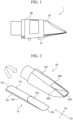
- FIG. 1 is a diagram showing a blowing part 1 according to a first embodiment of the present disclosure.
- FIG. 1 shows an example in which the blowing part 1 is viewed from a side.
- FIG. 2 is a diagram showing a reed 10 and a mouthpiece 30 according to the present embodiment.
- the blowing part 1 includes a reed 10, a mouthpiece 30, and a ligature 80.
- the ligature 80 is a member that fixes the reed 10 and the mouthpiece 30.
- the mouthpiece 30 includes a table 301, side rails 303, and a tip rail 300.
- Two side rails 303 extend from the table 301.
- the tip rail 300 extends from the two side rails 303.
- the tip rail 300 is disposed at an end portion of the side rails 303.
- the reed 10 includes a substrate part 101 and a vamp 103.
- the substrate part 101 includes a planar portion 151, a back surface 153, and a heel 157.
- the planar portion 151 is disposed on at least one surface of the substrate part 101.
- the back surface 153 is a surface opposite to the planar portion 151. In this example, the back surface 153 corresponds to at least a portion of a plane that contacts the table 301 when attached to the mouthpiece 30.
- the heel 157 is an end portion of the substrate part 101 located on the opposite side from the vamp 103.
- the vamp 103 extends from the substrate part 101 on the opposite side from the heel 157. That is, the vamp 103 is disposed at one end of the reed 10 in a longitudinal direction D1.
- the vamp 103 has a tip 155 on the opposite side from the substrate part 101 and gradually decreases in thickness towards the tip 155.
- the reed 10 is formed of a resin material and includes a longitudinal side and a short side.
- the longitudinal direction D1 and a short direction D2 of the reed 10 are perpendicular to each other.
- Elastic modulus of the reed 10 in the longitudinal direction D1 is relatively greater than elastic modulus of the reed 10 in the short direction D2.
- the elastic modulus in the longitudinal direction D1 of the reed 10 is equal to or greater than 1.1 times and equal to or less than 2.0 times the elastic modulus in the short direction D2 of the reed 10.
- rigidity of the reed 10 in the longitudinal direction D1 is relatively higher than rigidity of the reed 10 in the short direction D2.
- FIG. 3 is an enlarged view of the heel 157 of the reed 10 shown in FIG. 2 as viewed from the longitudinal direction D1.
- the reed 10 includes a plurality of plastic sheets 20.
- the reed 10 is formed of a laminate in which the plurality of plastic sheets 20 is laminated to each other.
- the plurality of plastic sheets 20 is laminated along a thickness direction D3 of the reed 10, perpendicular to both the longitudinal direction D1 and the short direction D2 of the reed 10. That is, in the present embodiment, a lamination direction of the plurality of plastic sheets 20 corresponds to the thickness direction D3 of the reed 10.
- FIG. 4 is a schematic diagram showing a side view of a laminate 200 including the plurality of plastic sheets 20.
- the laminate 200 includes about 5 to about 200 plastic sheets 20 laminated to each other.
- the plastic sheet 20 may be, but is not limited to, an LCP (Liquid Crystal Polymer) sheet having anisotropy of rigidity.
- LCP Liquid Crystal Polymer
- a resin sheet having anisotropy of rigidity such as PC (polycarbonate), PP (polypropylene), ABS (Acrylonitrile-butadiene-styrene), TPI (thermoplastic polyimide), PEI (polyetherimide), or the like, or a resin sheet easily having anisotropy of rigidity, is used in addition to LCP.
- a thickness of the plastic sheet 20 is not limited, but is usually equal to or greater than 5 ⁇ m and equal to or less than 5 mm, preferably equal to or greater than 10 ⁇ m and equal to or less than 1 mm, and more preferably equal to or greater than 20 ⁇ m and equal to or less than 200 ⁇ m.
- the thickness of the plastic sheet 20 is a thickness along the lamination direction of the plastic sheet 20 in the laminate 200.
- the laminate 200 including the plurality of plastic sheets 20 may include configurations other than the plastic sheets 20.
- the laminate 200 may include any layer interposed between two adjacent plastic sheets 20.
- the laminate 200 may include an adhesive layer interposed between two adjacent plastic sheets 20.
- the laminate 200 may include a sheet made of another type of resin different from the plurality of plastic sheets 20.
- At least one plastic sheet 20 has a stretching direction and a non-stretching direction. Both the stretching direction and the non-stretching direction are perpendicular to the thickness direction D3 of the reed 10, that is, the lamination direction of the plurality of plastic sheets 20, and the stretching direction and the non-stretching direction are perpendicular to each other.
- Elastic modulus of the plastic sheet 20 in the stretching direction is relatively larger than elastic modulus of the plastic sheet 20 in the non-stretching direction.
- rigidity of the plastic sheet 20 in the stretching direction is relatively higher than rigidity in the non-stretching direction.
- the elastic modulus in the stretching direction (a longitudinal direction) is equal to or greater than 1.1 times and equal to or less than 2.0 times the elastic modulus in the non-stretching direction (a short direction).
- the longitudinal direction D1 of the reed 10 corresponds to the stretching direction of the plastic sheet 20
- the short direction D2 of the reed 10 corresponds to a non-stretching direction of the plastic sheet 20.
- the reed 10 is cut out from the laminate 200 by cutting the laminate 200.
- the plate-shaped reed 10 is cut out from the laminate 200 so that long and short sides of the reed 10 are located in a direction perpendicular to the lamination direction of the plurality of plastic sheets 20 in the laminate 200.
- the elastic modulus of the reed 10 in the longitudinal direction D1 is larger than the elastic modulus of the reed 10 in the short direction D2.
- the rigidity of the reed 10 in the longitudinal direction D1 is greater than the rigidity of the reed 10 in the short direction D2.
- a plurality of reeds 10 can be cut out from one laminate 200.
- FIG. 5 is a cross-sectional view of the laminate 200 shown in FIG. 4 taken along A1-A2 line along a plane defined by the short direction D2 and the thickness direction D3 of the reed 10.
- FIG. 5 shows a cross-sectional view as viewed from the longitudinal direction D1 of the reed 10.
- the plastic sheet 20 includes a first layer 201 and a second layer 203.
- the second layer 203 adjoins the first layer 201 in the lamination direction of the plurality of plastic sheets 20 (that is, the thickness direction D3 of the reed 10).
- Anisotropy of elastic modulus of the first layer 201 of the plastic sheet 20 is different from anisotropy of elastic modulus of the second layer 203.
- the anisotropy of the elastic modulus of the second layer 203 may be larger than the anisotropy of the elastic modulus of the first layer 201.
- the anisotropy of the elastic modulus of the first layer 201 may be larger than the anisotropy of the elastic modulus of the second layer 203.
- the plastic sheets 20 may be laminated so that directions in which the anisotropy of rigidity is relatively strong are aligned. As a result, the laminate 200 having anisotropy of rigidity can be formed.
- the plurality of plastic sheets 20 when the plurality of plastic sheets 20 are laminated, the plurality of plastic sheets 20 may be laminated so that the directions in which the anisotropy of the rigidity is relatively strong are not intentionally aligned. Further, by interposing another member between the plurality of plastic sheets 20, it is possible to adjust anisotropy of rigidity of the laminate 200. Further, by making the thickness of the plastic sheet 20 thinner and increasing a number of laminated plastic sheets 20 in the laminate 200, it is possible to adjust a ratio of the first layer 201 or the second layer 203 having a relatively large anisotropy of rigidity in the laminate 200 and to adjust the anisotropy of the rigidity of the laminate 200.
- the laminate 200 having the anisotropy in the rigidity is formed.
- the reed 10 cut out from this laminate 200 has anisotropy in rigidity as the laminate 200.
- anisotropy of rigidity similar to anisotropy of rigidity of the plant-based reed can be imparted to the reed 10. Therefore, the reed 10 can realize the same tone as that of the plant-based reed.
- the anisotropy of the rigidity of the reed 10 is realized not only by a surface of the reed 10 but also by the plurality of plastic sheets 20 constituting the reed 10. Therefore, even if the reed 10 is surface-treated and the surface of the reed 10 is scraped in order to form the vamp 103 or the like after the reed 10 is cut out from the laminate 200, the anisotropy of the rigidity of the reed 10 is maintained.
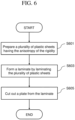
- FIG. 6 is a flowchart showing an example of a method of manufacturing the reed 10 according to the present embodiment.
- FIG. 7 to FIG. 9 are diagrams for explaining a manufacturing process of the reed 10.
- the plurality of plastic sheets 20 having the anisotropy of the rigidity is prepared (S601).
- the plastic sheet 20 is prepared from about 5 sheets to about 200 sheets.
- the elastic modulus in the stretching direction is larger than the elastic modulus in the non-stretching direction.
- the elastic modulus of the plastic sheet 20 in the stretching direction is equal to or greater than 1.1 times and equal to or less than 2.0 times the elastic modulus in the non-stretching direction.
- the configuration of the plastic sheet 20 includes the first layer 201 and the second layer 203 adjacent to the first layer 201, as described with reference to FIG. 5 .
- the anisotropy of the elastic modulus of the first layer 201 is different from the anisotropy of the elastic modulus of the second layer 203.
- the second layer 203 is adjacent to the first layer 201 in the lamination direction of the plurality of plastic sheets 20.
- the plurality of plastic sheets 20 are laminated in a direction perpendicular to both the stretching direction and the non-stretching direction to form the laminate 200 (S603).
- the lamination direction of the plurality of plastic sheets 20 corresponds to the thickness direction D3 of the reed 10.
- the plurality of plastic sheets 20 may be laminated so that the anisotropy of the rigidity of each of the plurality of plastic sheets 20 is aligned.
- the plurality of plastic sheets 20 may be laminated so that the directions in which the anisotropy of the rigidity of each of the plurality of plastic sheets 20 is relatively strong are aligned.
- the plurality of plastic sheets 20 may be laminated so that the directions in which the anisotropy of the rigidity is relatively strong are not intentionally aligned.
- Elastic modulus in a longitudinal direction of the laminate 200 in which the plurality of plastic sheets 20 are laminated is equal to or greater than 1.1 times and equal to or less than 2.0 times elastic modulus in a short direction.
- the laminate 200 may include a member interposed between two adjacent plastic sheets 20 of the plurality of plastic sheets 20.
- the member interposed between the two plastic sheets 20 may be a sheet made of another type of resin, an adhesive layer, or the like, which is different from the plastic sheet 20.
- the plurality of plastic sheets 20 may be bonded to each other by being crimped. Various conditions such as temperature, pressure, and press time when the plurality of plastic sheets 20 are crimped are appropriately set in accordance with a type of resin used for the plastic sheet 20. In addition, the plurality of plastic sheets 20 may be bonded to each other by an adhesive interposed between two adjacent plastic sheets 20.
- a plate 210 is cut out from the laminate 200 by cutting process (S605).
- the plate 210 is cut out from the laminate 200 such that a longitudinal direction of the plate 210 matches the longitudinal direction of the laminate 200 and a short direction of the plate 210 matches the short direction of the laminate 200. That is, the plate 210 is cut out along a direction perpendicular to the lamination direction in which the plurality of plastic sheets 20 are laminated in the laminate 200. Therefore, elastic modulus of the plate 210 in the longitudinal direction is larger than elastic modulus of the plate 210 in the short direction.
- the plate 210 cut out by process of S605 becomes the reed 10. That is, the longitudinal direction D1 of the reed 10 and the longitudinal direction of the plate 210 march each other, and the short direction D2 of the reed 10 and the short direction of the plate 210 match each other.
- the plate 210 may be treated on its surface to form the vamp 103 or the like of the reed 10. The above is the manufacturing method of the reed 10 according to the present embodiment.
- a reed 10A according to a second embodiment of the present disclosure will be described.
- An exterior of the reed 10A is the same as the reed 10 according to the first embodiment shown in FIG. 2 .
- the reed 10A differing from the reed 10 according to the first embodiment is explain.
- FIG. 10 is an enlarged view of a heel 157A of the reed 10A as viewed from a longitudinal direction D1 of the reed 10A.
- the reed 10A includes the plurality of plastic sheets 20.
- the reed 10A is formed of a laminate in which the plurality of plastic sheets 20 are laminated along a short direction D2 of the reed 10A. That is, the short direction D2 of the reed 10A and the lamination direction of the plurality of plastic sheets 20 match each other in the present embodiment.
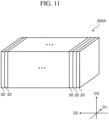
- FIG. 11 is a schematic diagram showing a laminate 200A including the plurality of plastic sheets 20.
- the laminate 200A includes about 5 sheets to about 200 sheets of the plastic sheets 20 laminated to each other.
- the plastic sheet 20 constituting the laminate 200 in the first embodiment can be used.
- the laminate 200A may include configurations other than the plastic sheet 20.
- the laminate 200A may include any layers interposed between two adjacent plastic sheets 20.
- the laminate 200A may include an adhesive layer interposed between two adjacent plastic sheets 20.
- the laminate 200A may include a sheet made of another type of plastic that differs from the plurality of plastic sheets 20.
- the reed 10A is manufactured by cutting the laminate 200A. As shown in FIG. 10 , the lamination direction of the plurality of plastic sheets 20 constituting the reed 10A matches the short direction D2 of the reed 10A. In this case, the plate-shaped reed 10A is cut out from the laminate 200A along the lamination direction of the plurality of plastic sheets 20 so that the lamination direction of the plurality of plastic sheets 20 in the laminate 200A matches the short direction D2 of the reed 10A and the stretching direction of the plastic sheets 20 matches the longitudinal direction D1 of the reed 10A.
- elastic modulus of the reed 10A in the longitudinal direction D1 is larger than elastic modulus of the reed 10A in the short direction D2.
- rigidity of the reed 10A in the longitudinal direction D1 is greater than rigidity of the reed 10A in the short direction D2.
- a plurality of reed 10A can be cut out from one laminate 200A.
- each of the plurality of plastic sheets 20 constituting the reed 10A is the same as the plastic sheet 20 in the first embodiment, illustration thereof is omitted.
- the plastic sheet 20 includes the first layer 201 and a second layer 203 adjacent to the first layer 201.
- the anisotropy of the elastic modulus of the first layer 201 is different from the anisotropy of the elastic modulus of the second layer 203.
- the second layer 203 is adjacent to the first layer 201 in the lamination direction of the plurality of plastic sheets 20.
- the elastic modulus in the stretching direction perpendicular to the lamination direction of the plastic sheet 20 is relatively larger than the elastic modulus in the non-stretching direction perpendicular to the lamination direction.
- the rigidity of the plastic sheet 20 in the stretching direction is relatively larger than the rigidity of the plastic sheet 20 in the non-stretching direction.
- the elastic modulus in the stretching direction is equal to or greater than 1.1 times and equal to or less than 2.0 times the elastic modulus in the non-stretching direction.
- the elastic modulus of the each of the plastic sheets 20 constituting the laminate 200A in the stretching direction perpendicular to the lamination direction shown in FIG. 11 may be larger than the elastic modulus of the each of the plastic sheets 20 in the non-stretching direction perpendicular to both the lamination direction and the stretching direction.
- the stretching direction may be longitudinal direction D1 of the reed 10A
- the non-stretching direction may be a thickness direction D3 of the reed 10A.
- the laminate 200A having anisotropy of rigidity is formed.
- the reed 10A cut out from the laminate 200A has anisotropy of rigidity.
- anisotropy of rigidity similar to the anisotropy of the rigidity of the plant-based reed can be imparted to the reed 10A. Therefore, the reed 10A can realize the same tone as that of the plant-based reed.
- the anisotropy of the rigidity of the reed 10A is realized not only by a surface of the reed 10A but also by the plurality of plastic sheets 20 constituting the reed 10A. Therefore, even if the reed 10A is surface-treated and the surface of the reed 10A is scraped in order to form the vamp 103 or the like after the reed 10A is cut out from the laminate 200A, the anisotropy of the rigidity of the reed 10A is maintained.
- the method of manufacturing the reed 10A according to the present embodiment is the same as the method of manufacturing the reed 10 described with reference to FIG. 6 to FIG. 8 except the lamination direction of the plurality of plastic sheets and cutting out the plate from the laminate 200A along the lamination direction of the plurality of plastic sheets 20 when cutting out the plate to become the lead 10A from the laminate 200A including the plurality of plastic sheets 20, and thus detailed explanation thereof is omitted.
- the blowing part 1 of the present disclosure is not limited to the blowing part of the saxophone, and may be any blowing part of an aerophone.
- the aerophone may be a woodwind.
- the woodwind include clarinet, oboe, fagot (bason), and the like in addition to saxophone. It is also applicable to folk instruments such as bagpipe and period instruments such as shawm.
- a 3D printed layer output by a 3D printer may be used instead of a plastic sheet.
- the 3D printed layer like the plastic sheet, has anisotropic rigidity, and an elastic modulus in a longitudinal direction is greater than that in a short direction.
- the elastic modulus of the 3D printed layer in the longitudinal direction is equal to or greater than 1.1 times and equal to or less than 2.0 times the modulus in the short direction.
- the laminate 200, 200A in the embodiments described above may be formed by the 3D printer.
- a reed whose rigidity in the longitudinal direction is greater than the rigidity in the short direction may be produced by the 3D printer.
Landscapes
- Engineering & Computer Science (AREA)
- Physics & Mathematics (AREA)
- Acoustics & Sound (AREA)
- Multimedia (AREA)
- Manufacturing & Machinery (AREA)
- Mechanical Engineering (AREA)
- Laminated Bodies (AREA)
Abstract
According to an embodiment, a reed for an aerophone, the reed including a plurality of plastic sheets laminated in a lamination direction perpendicular to a longitudinal direction of the reed is provided, and an elastic modulus in the longitudinal direction of at least one plastic sheet of the plurality of plastic sheets is greater than an elastic modulus in a direction perpendicular to both the lamination direction and the longitudinal direction of the at least one plastic sheet.
Description
- This application claims the benefit of priority to
Japanese Patent Application No. 2023-041923, filed on March 16, 2023 - The present disclosure relates to a reed of a wind instrument and a manufacturing method thereof.
- A reed attached to a mouthpiece of a wind instrument is formed by a plant material commonly referred to as canes. In recent years, for example, a reed formed of a resin material has also been developed as disclosed in
Japanese Laid-Open Patent Publication No. 2001-075556 - According to an embodiment of the present disclosure, there is provided a reed for an aerophone, the reed including a plurality of plastic sheets laminated in a lamination direction perpendicular to a longitudinal direction of the reed, wherein an elastic modulus in the longitudinal direction of at least one plastic sheet of the plurality of plastic sheets is greater than an elastic modulus in a direction perpendicular to both the lamination direction and the longitudinal direction of the at least one plastic sheet.
- According to an embodiment of the present disclosure, there is provided a reed manufacturing method, the method including preparing a plurality of plastic sheets, each plastic sheet of the plurality of plastic sheets having anisotropy, forming a laminate by laminating the plurality of plastic sheets with the anisotropy aligned, and cutting out a plate from the laminate to form the reed such that an elastic modulus in a longitudinal direction of the reed is greater than an elastic modulus in a short direction of the reed perpendicular to the longitudinal direction of the reed.
-
-
FIG. 1 is a view showing a blowing part according to an embodiment. -
FIG. 2 shows a reed and a mouthpiece according to an embodiment. -
FIG. 3 is an enlarged longitudinal view of a heel of a reed according to an embodiment. -
FIG. 4 is a schematic diagram showing a laminate including a plurality of plastic sheets according to an embodiment. -
FIG. 5 is an example of a cross-sectional view of a laminate of plastic sheets along A1-A2 inFIG. 4 . -
FIG. 6 is a flowchart showing an example of a reed manufacturing method according to an embodiment. -
FIG. 7 is a diagram for explaining a reed manufacturing process according to an embodiment. -
FIG. 8 is a diagram for explaining a reed manufacturing process according to an embodiment. -
FIG. 9 is a diagram for explaining a reed manufacturing process according to an embodiment. -
FIG. 10 is an enlarged longitudinal view of a heel of a reed according to another embodiment. -
FIG. 11 is a schematic diagram showing a laminate including a plurality of plastic sheets according to another embodiment. - A reed formed of a plant material (hereinafter referred to as a plant-based reed) is different in physical properties from a reed formed of a resin material (hereinafter referred to as a resin derived reed). Specifically, the plant-based reed is characterized in that, at its tip, rigidity in a lateral direction substantially orthogonal to an extending direction (longitudinal direction) of the reed body is relatively low compared to rigidity in the longitudinal direction, and elastic modulus in the lateral direction is low and is easy to bent compared to the longitudinal direction. Such anisotropy of the rigidity allows the plant-based reed to realize a variety of tones. On the other hand, unlike the plant-based reed, the resin derived reed has no anisotropy of the rigidity in the longitudinal direction and the lateral direction. Therefore, the resin derived reed cannot reproduce the tone of the plant-based reed. It is desired to realize various tones by the resin derived reed, including making a sound generation by the resin derived reed closer to a sound generation by the plant-based reed.
- It is difficult to impart anisotropy of a desired rigidity to a resin derived reed that is cut out from a resin material or is produced by injection molding.
- According to the present disclosure, various tones can be realized by a reed formed of a material other than plant material.
- Hereinafter, an embodiment of the present disclosure will be described in detail with reference to the drawings. The following embodiments are examples, and the present disclosure should not be construed as being limited to these embodiments. In the drawings referred to in the present embodiment, the same or similar parts are denoted by the same reference signs or similar reference signs (only denoted by A, B, and the like after the numerals), and repetitive description thereof may be omitted. In the drawings, dimensional ratios may be different from actual ratios, or a part of the configuration may be omitted from the drawings for clarity of explanation.
- For example, a blowing part according to an embodiment is a single-reed blowing part used in a saxophone, and includes a reed. The reed is formed of a resin material.
-
FIG. 1 is a diagram showing a blowing part 1 according to a first embodiment of the present disclosure.FIG. 1 shows an example in which the blowing part 1 is viewed from a side.FIG. 2 is a diagram showing areed 10 and amouthpiece 30 according to the present embodiment. - As shown in
FIG. 1 , the blowing part 1 includes areed 10, amouthpiece 30, and aligature 80. Theligature 80 is a member that fixes thereed 10 and themouthpiece 30. - As shown in
FIG. 2 , themouthpiece 30 includes a table 301,side rails 303, and atip rail 300. Twoside rails 303 extend from the table 301. Thetip rail 300 extends from the twoside rails 303. Thetip rail 300 is disposed at an end portion of theside rails 303. - The
reed 10 includes asubstrate part 101 and avamp 103. As shown inFIG. 2 , thesubstrate part 101 includes aplanar portion 151, aback surface 153, and aheel 157. Theplanar portion 151 is disposed on at least one surface of thesubstrate part 101. Theback surface 153 is a surface opposite to theplanar portion 151. In this example, theback surface 153 corresponds to at least a portion of a plane that contacts the table 301 when attached to themouthpiece 30. Theheel 157 is an end portion of thesubstrate part 101 located on the opposite side from thevamp 103. - The
vamp 103 extends from thesubstrate part 101 on the opposite side from theheel 157. That is, thevamp 103 is disposed at one end of thereed 10 in a longitudinal direction D1. Thevamp 103 has atip 155 on the opposite side from thesubstrate part 101 and gradually decreases in thickness towards thetip 155. - The
reed 10 is formed of a resin material and includes a longitudinal side and a short side. The longitudinal direction D1 and a short direction D2 of thereed 10 are perpendicular to each other. Elastic modulus of thereed 10 in the longitudinal direction D1 is relatively greater than elastic modulus of thereed 10 in the short direction D2. The elastic modulus in the longitudinal direction D1 of thereed 10 is equal to or greater than 1.1 times and equal to or less than 2.0 times the elastic modulus in the short direction D2 of thereed 10. In other words, rigidity of thereed 10 in the longitudinal direction D1 is relatively higher than rigidity of thereed 10 in the short direction D2. -
FIG. 3 is an enlarged view of theheel 157 of thereed 10 shown inFIG. 2 as viewed from the longitudinal direction D1. As shown inFIG. 3 , thereed 10 includes a plurality ofplastic sheets 20. Thereed 10 is formed of a laminate in which the plurality ofplastic sheets 20 is laminated to each other. The plurality ofplastic sheets 20 is laminated along a thickness direction D3 of thereed 10, perpendicular to both the longitudinal direction D1 and the short direction D2 of thereed 10. That is, in the present embodiment, a lamination direction of the plurality ofplastic sheets 20 corresponds to the thickness direction D3 of thereed 10. -
FIG. 4 is a schematic diagram showing a side view of a laminate 200 including the plurality ofplastic sheets 20. The laminate 200 includes about 5 to about 200plastic sheets 20 laminated to each other. Theplastic sheet 20 may be, but is not limited to, an LCP (Liquid Crystal Polymer) sheet having anisotropy of rigidity. As theplastic sheet 20, a resin sheet having anisotropy of rigidity, such as PC (polycarbonate), PP (polypropylene), ABS (Acrylonitrile-butadiene-styrene), TPI (thermoplastic polyimide), PEI (polyetherimide), or the like, or a resin sheet easily having anisotropy of rigidity, is used in addition to LCP. A thickness of theplastic sheet 20 is not limited, but is usually equal to or greater than 5 µm and equal to or less than 5 mm, preferably equal to or greater than 10 µm and equal to or less than 1 mm, and more preferably equal to or greater than 20 µm and equal to or less than 200 µm. Here, the thickness of theplastic sheet 20 is a thickness along the lamination direction of theplastic sheet 20 in thelaminate 200. - The laminate 200 including the plurality of
plastic sheets 20 may include configurations other than theplastic sheets 20. The laminate 200 may include any layer interposed between twoadjacent plastic sheets 20. Although not shown, for example, the laminate 200 may include an adhesive layer interposed between twoadjacent plastic sheets 20. In addition, the laminate 200 may include a sheet made of another type of resin different from the plurality ofplastic sheets 20. - Among the plurality of
plastic sheets 20 constituting thereed 10, at least oneplastic sheet 20 has a stretching direction and a non-stretching direction. Both the stretching direction and the non-stretching direction are perpendicular to the thickness direction D3 of thereed 10, that is, the lamination direction of the plurality ofplastic sheets 20, and the stretching direction and the non-stretching direction are perpendicular to each other. Elastic modulus of theplastic sheet 20 in the stretching direction is relatively larger than elastic modulus of theplastic sheet 20 in the non-stretching direction. In other words, rigidity of theplastic sheet 20 in the stretching direction is relatively higher than rigidity in the non-stretching direction. In theplastic sheet 20, the elastic modulus in the stretching direction (a longitudinal direction) is equal to or greater than 1.1 times and equal to or less than 2.0 times the elastic modulus in the non-stretching direction (a short direction). - For example, in each of the
plastic sheets 20 constituting the laminate 200 shown inFIG. 4 , the longitudinal direction D1 of thereed 10 corresponds to the stretching direction of theplastic sheet 20, and the short direction D2 of thereed 10 corresponds to a non-stretching direction of theplastic sheet 20. When thereed 10 is cut out from the laminate 200, thereed 10 is cut out from the laminate 200 such that the stretching direction of each of theplastic sheets 20 matches the longitudinal direction D1 of thereeds 10 and the non-stretching direction matches the short direction D2 of thereed 10. - The
reed 10 is cut out from the laminate 200 by cutting thelaminate 200. As shown inFIG. 3 , in the case where the thickness direction D3 of thereed 10 and the lamination direction of the plurality ofplastic sheets 20 constituting thereed 10 match, the plate-shapedreed 10 is cut out from the laminate 200 so that long and short sides of thereed 10 are located in a direction perpendicular to the lamination direction of the plurality ofplastic sheets 20 in thelaminate 200. Here, the elastic modulus of thereed 10 in the longitudinal direction D1 is larger than the elastic modulus of thereed 10 in the short direction D2. In other words, the rigidity of thereed 10 in the longitudinal direction D1 is greater than the rigidity of thereed 10 in the short direction D2. Depending on a size of theplastic sheet 20, a plurality ofreeds 10 can be cut out from onelaminate 200. -
FIG. 5 is a cross-sectional view of the laminate 200 shown inFIG. 4 taken along A1-A2 line along a plane defined by the short direction D2 and the thickness direction D3 of thereed 10.FIG. 5 shows a cross-sectional view as viewed from the longitudinal direction D1 of thereed 10. As shown inFIG. 5 , theplastic sheet 20 includes afirst layer 201 and asecond layer 203. Thesecond layer 203 adjoins thefirst layer 201 in the lamination direction of the plurality of plastic sheets 20 (that is, the thickness direction D3 of the reed 10). Anisotropy of elastic modulus of thefirst layer 201 of theplastic sheet 20 is different from anisotropy of elastic modulus of thesecond layer 203. For example, the anisotropy of the elastic modulus of thesecond layer 203 may be larger than the anisotropy of the elastic modulus of thefirst layer 201. Alternatively, conversely, the anisotropy of the elastic modulus of thefirst layer 201 may be larger than the anisotropy of the elastic modulus of thesecond layer 203. By forming the laminate 200 by laminating the plurality of suchplastic sheets 20, thefirst layer 201 and thesecond layer 203 are alternately located in at least a part of the laminate 200 along the lamination direction of theplastic sheets 20. - In the case where two or more
plastic sheets 20 constituting thereed 10 have anisotropy of rigidity, theplastic sheets 20 may be laminated so that directions in which the anisotropy of rigidity is relatively strong are aligned. As a result, the laminate 200 having anisotropy of rigidity can be formed. - In the case of adjusting the anisotropy of the rigidity of the laminate 200, when the plurality of
plastic sheets 20 are laminated, the plurality ofplastic sheets 20 may be laminated so that the directions in which the anisotropy of the rigidity is relatively strong are not intentionally aligned. Further, by interposing another member between the plurality ofplastic sheets 20, it is possible to adjust anisotropy of rigidity of the laminate 200. Further, by making the thickness of theplastic sheet 20 thinner and increasing a number of laminatedplastic sheets 20 in the laminate 200, it is possible to adjust a ratio of thefirst layer 201 or thesecond layer 203 having a relatively large anisotropy of rigidity in the laminate 200 and to adjust the anisotropy of the rigidity of the laminate 200. - As described above, by laminating the plurality of
plastic sheets 20 having the anisotropy of the rigidity, the laminate 200 having the anisotropy in the rigidity is formed. Thereed 10 cut out from thislaminate 200 has anisotropy in rigidity as thelaminate 200. In other words, anisotropy of rigidity similar to anisotropy of rigidity of the plant-based reed can be imparted to thereed 10. Therefore, thereed 10 can realize the same tone as that of the plant-based reed. - Further, the anisotropy of the rigidity of the
reed 10 is realized not only by a surface of thereed 10 but also by the plurality ofplastic sheets 20 constituting thereed 10. Therefore, even if thereed 10 is surface-treated and the surface of thereed 10 is scraped in order to form thevamp 103 or the like after thereed 10 is cut out from the laminate 200, the anisotropy of the rigidity of thereed 10 is maintained. -
FIG. 6 is a flowchart showing an example of a method of manufacturing thereed 10 according to the present embodiment.FIG. 7 to FIG. 9 are diagrams for explaining a manufacturing process of thereed 10. - First, as shown in
FIG. 6 andFIG. 7 , the plurality ofplastic sheets 20 having the anisotropy of the rigidity is prepared (S601). For example, theplastic sheet 20 is prepared from about 5 sheets to about 200 sheets. In each of theplastic sheets 20, the elastic modulus in the stretching direction is larger than the elastic modulus in the non-stretching direction. Here, the elastic modulus of theplastic sheet 20 in the stretching direction is equal to or greater than 1.1 times and equal to or less than 2.0 times the elastic modulus in the non-stretching direction. - The configuration of the
plastic sheet 20 includes thefirst layer 201 and thesecond layer 203 adjacent to thefirst layer 201, as described with reference toFIG. 5 . The anisotropy of the elastic modulus of thefirst layer 201 is different from the anisotropy of the elastic modulus of thesecond layer 203. Thesecond layer 203 is adjacent to thefirst layer 201 in the lamination direction of the plurality ofplastic sheets 20. - Next, as shown in
FIG. 6 andFIG. 8 , the plurality ofplastic sheets 20 are laminated in a direction perpendicular to both the stretching direction and the non-stretching direction to form the laminate 200 (S603). The lamination direction of the plurality ofplastic sheets 20 corresponds to the thickness direction D3 of thereed 10. At this time, the plurality ofplastic sheets 20 may be laminated so that the anisotropy of the rigidity of each of the plurality ofplastic sheets 20 is aligned. Specifically, the plurality ofplastic sheets 20 may be laminated so that the directions in which the anisotropy of the rigidity of each of the plurality ofplastic sheets 20 is relatively strong are aligned. - Further, in order to adjust the anisotropy of the rigidity of the laminate 200, when the plurality of
plastic sheets 20 are laminated, the plurality ofplastic sheets 20 may be laminated so that the directions in which the anisotropy of the rigidity is relatively strong are not intentionally aligned. Elastic modulus in a longitudinal direction of the laminate 200 in which the plurality ofplastic sheets 20 are laminated is equal to or greater than 1.1 times and equal to or less than 2.0 times elastic modulus in a short direction. - Although not shown in the drawing, the laminate 200 may include a member interposed between two
adjacent plastic sheets 20 of the plurality ofplastic sheets 20. The member interposed between the twoplastic sheets 20 may be a sheet made of another type of resin, an adhesive layer, or the like, which is different from theplastic sheet 20. - The plurality of
plastic sheets 20 may be bonded to each other by being crimped. Various conditions such as temperature, pressure, and press time when the plurality ofplastic sheets 20 are crimped are appropriately set in accordance with a type of resin used for theplastic sheet 20. In addition, the plurality ofplastic sheets 20 may be bonded to each other by an adhesive interposed between twoadjacent plastic sheets 20. - Next, as shown in
FIG. 6 andFIG. 9 , aplate 210 is cut out from the laminate 200 by cutting process (S605). In this case, theplate 210 is cut out from the laminate 200 such that a longitudinal direction of theplate 210 matches the longitudinal direction of the laminate 200 and a short direction of theplate 210 matches the short direction of the laminate 200. That is, theplate 210 is cut out along a direction perpendicular to the lamination direction in which the plurality ofplastic sheets 20 are laminated in thelaminate 200. Therefore, elastic modulus of theplate 210 in the longitudinal direction is larger than elastic modulus of theplate 210 in the short direction. - The
plate 210 cut out by process of S605 becomes thereed 10. That is, the longitudinal direction D1 of thereed 10 and the longitudinal direction of theplate 210 march each other, and the short direction D2 of thereed 10 and the short direction of theplate 210 match each other. Although not shown in the drawing, theplate 210 may be treated on its surface to form thevamp 103 or the like of thereed 10. The above is the manufacturing method of thereed 10 according to the present embodiment. - A
reed 10A according to a second embodiment of the present disclosure will be described. An exterior of thereed 10A is the same as thereed 10 according to the first embodiment shown inFIG. 2 . Hereinafter, thereed 10A differing from thereed 10 according to the first embodiment is explain. -
FIG. 10 is an enlarged view of aheel 157A of thereed 10A as viewed from a longitudinal direction D1 of thereed 10A. As shown inFIG. 10 , thereed 10A includes the plurality ofplastic sheets 20. Unlike thereed 10, thereed 10A is formed of a laminate in which the plurality ofplastic sheets 20 are laminated along a short direction D2 of thereed 10A. That is, the short direction D2 of thereed 10A and the lamination direction of the plurality ofplastic sheets 20 match each other in the present embodiment. -
FIG. 11 is a schematic diagram showing alaminate 200A including the plurality ofplastic sheets 20. Thelaminate 200A includes about 5 sheets to about 200 sheets of theplastic sheets 20 laminated to each other. As theplastic sheet 20, theplastic sheet 20 constituting the laminate 200 in the first embodiment can be used. - The
laminate 200A may include configurations other than theplastic sheet 20. Thelaminate 200A may include any layers interposed between twoadjacent plastic sheets 20. Although not shown in the drawing, for example, thelaminate 200A may include an adhesive layer interposed between twoadjacent plastic sheets 20. In addition, thelaminate 200A may include a sheet made of another type of plastic that differs from the plurality ofplastic sheets 20. - The
reed 10A is manufactured by cutting thelaminate 200A. As shown inFIG. 10 , the lamination direction of the plurality ofplastic sheets 20 constituting thereed 10A matches the short direction D2 of thereed 10A. In this case, the plate-shapedreed 10A is cut out from thelaminate 200A along the lamination direction of the plurality ofplastic sheets 20 so that the lamination direction of the plurality ofplastic sheets 20 in thelaminate 200A matches the short direction D2 of thereed 10A and the stretching direction of theplastic sheets 20 matches the longitudinal direction D1 of thereed 10A. Therefore, in the plate-shapedreed 10A cut out from thelaminate 200A, elastic modulus of thereed 10A in the longitudinal direction D1 is larger than elastic modulus of thereed 10A in the short direction D2. In other words, rigidity of thereed 10A in the longitudinal direction D1 is greater than rigidity of thereed 10A in the short direction D2. Depending on the size of theplastic sheet 20, a plurality ofreed 10A can be cut out from onelaminate 200A. - Since each of the plurality of
plastic sheets 20 constituting thereed 10A is the same as theplastic sheet 20 in the first embodiment, illustration thereof is omitted. Theplastic sheet 20 includes thefirst layer 201 and asecond layer 203 adjacent to thefirst layer 201. The anisotropy of the elastic modulus of thefirst layer 201 is different from the anisotropy of the elastic modulus of thesecond layer 203. Thesecond layer 203 is adjacent to thefirst layer 201 in the lamination direction of the plurality ofplastic sheets 20. - In at least one
plastic sheet 20 of the plurality ofplastic sheets 20 constituting thereed 10A, the elastic modulus in the stretching direction perpendicular to the lamination direction of theplastic sheet 20 is relatively larger than the elastic modulus in the non-stretching direction perpendicular to the lamination direction. In other words, the rigidity of theplastic sheet 20 in the stretching direction is relatively larger than the rigidity of theplastic sheet 20 in the non-stretching direction. In theplastic sheet 20, the elastic modulus in the stretching direction is equal to or greater than 1.1 times and equal to or less than 2.0 times the elastic modulus in the non-stretching direction. - For example, the elastic modulus of the each of the
plastic sheets 20 constituting thelaminate 200A in the stretching direction perpendicular to the lamination direction shown inFIG. 11 may be larger than the elastic modulus of the each of theplastic sheets 20 in the non-stretching direction perpendicular to both the lamination direction and the stretching direction. In this case, the stretching direction may be longitudinal direction D1 of thereed 10A, and the non-stretching direction may be a thickness direction D3 of thereed 10A. - As described above, by laminating the plurality of
plastic sheets 20 having the anisotropy of the rigidity, thelaminate 200A having anisotropy of rigidity is formed. Like the laminate 200A, thereed 10A cut out from the laminate 200A has anisotropy of rigidity. In other words, anisotropy of rigidity similar to the anisotropy of the rigidity of the plant-based reed can be imparted to thereed 10A. Therefore, thereed 10A can realize the same tone as that of the plant-based reed. - Further, the anisotropy of the rigidity of the
reed 10A is realized not only by a surface of thereed 10A but also by the plurality ofplastic sheets 20 constituting thereed 10A. Therefore, even if thereed 10A is surface-treated and the surface of thereed 10A is scraped in order to form thevamp 103 or the like after thereed 10A is cut out from thelaminate 200A, the anisotropy of the rigidity of thereed 10A is maintained. - The method of manufacturing the
reed 10A according to the present embodiment is the same as the method of manufacturing thereed 10 described with reference toFIG. 6 to FIG. 8 except the lamination direction of the plurality of plastic sheets and cutting out the plate from thelaminate 200A along the lamination direction of the plurality ofplastic sheets 20 when cutting out the plate to become the lead 10A from thelaminate 200A including the plurality ofplastic sheets 20, and thus detailed explanation thereof is omitted. - The present disclosure is not limited to the embodiments described above, and includes various other modifications. For example, the embodiments described above have been described in detail for the purpose of showing the present disclosure in an easy-to-understand manner, and are not necessarily limited to those having all the described configurations. That is, a part of the configuration of each embodiment may be replaced with another configuration or may be deleted. Some modifications will be described below. The modifications described below can be applied to any of the first embodiment and the second embodiment described above.
- The blowing part 1 of the present disclosure is not limited to the blowing part of the saxophone, and may be any blowing part of an aerophone. The aerophone may be a woodwind. For example, the woodwind include clarinet, oboe, fagot (bason), and the like in addition to saxophone. It is also applicable to folk instruments such as bagpipe and period instruments such as shawm.
- In the embodiments described above, the reed is formed by laminating the plurality of
plastic sheets 20 having the anisotropy in the rigidity. Each of theplastic sheets 20 includes thefirst layer 201 and thesecond layer 203 having different elastic modulus (rigidity) from each other. However, the reed of the present disclosure is not limited thereto. For example, a laminate including a plurality of plastic sheets may be formed by laminating a plurality of plastic sheets having uniform anisotropy of rigidity on the sheet itself. - In the embodiments described above, a 3D printed layer output by a 3D printer may be used instead of a plastic sheet. In this case, the 3D printed layer, like the plastic sheet, has anisotropic rigidity, and an elastic modulus in a longitudinal direction is greater than that in a short direction. The elastic modulus of the 3D printed layer in the longitudinal direction is equal to or greater than 1.1 times and equal to or less than 2.0 times the modulus in the short direction. In addition, the laminate 200, 200A in the embodiments described above may be formed by the 3D printer. Furthermore, a reed whose rigidity in the longitudinal direction is greater than the rigidity in the short direction may be produced by the 3D printer.
Claims (12)
- A reed for an aerophone, the reed comprising:a plurality of plastic sheets laminated in a lamination direction perpendicular to a longitudinal direction of the reed,wherein an elastic modulus in a longitudinal direction of at least one plastic sheet of the plurality of plastic sheets is greater than an elastic modulus in a direction perpendicular to both the lamination direction and the longitudinal direction of the at least one plastic sheet.
- The reed according to claim 1, wherein the elastic modulus in the longitudinal direction of the at least one plastic sheet is equal to or greater than 1.1 times and equal to or less than 2.0 times the elastic modulus in a short direction of at least one plastic sheet.
- The reed according to claim 1, wherein the elastic modulus in the longitudinal direction of the reed is equal to or greater than 1.1 times and equal to or less than 2.0 times the elastic modulus in a short direction of the reed.
- The reed according to claim 1, wherein:the at least one plastic sheet of the plurality of plastic sheets comprises a first layer and a second layer adjacent to the first layer in the lamination direction; andan anisotropy of an elastic modulus of the first layer is different from an anisotropy of an elastic modulus of the second layer.
- The reed according to claim 1, wherein the lamination direction is a same direction as a short direction of the reed.
- The reed according to claim 1, wherein the lamination direction is a direction perpendicular to both the longitudinal direction of the reed and a short direction of the reed.
- A reed manufacturing method comprising:preparing a plurality of plastic sheets, each plastic sheet of the plurality of plastic sheets having anisotropy;forming a laminate by laminating the plurality of plastic sheets with the anisotropy aligned; andcutting out a plate from the laminate to form the reed such that an elastic modulus in a longitudinal direction of the reed is greater than an elastic modulus in a short direction of the reed perpendicular to the longitudinal direction of the reed.
- The reed manufacturing method according to claim 7, wherein the elastic modulus in the longitudinal direction of the reed is equal to or greater than 1.1 times and equal to or less than 2.0 times the elastic modulus in the short direction of the reed.
- The reed manufacturing method according to claim 7, whereinat least one plastic sheet of the plurality of plastic sheets comprises a first layer and a second layer adjacent to the first layer in a lamination direction; andan anisotropy of an elastic modulus of the first layer is different from an anisotropy of an elastic modulus of the second layer.
- The reed manufacturing method according to claim 7, wherein cutting out the plate includes cutting out the plate from the laminate along a lamination direction of the plurality of plastic sheets.
- The reed manufacturing method according to claim 7, wherein cutting out the plate includes cutting out the plate from the laminate along a direction perpendicular to a lamination direction of the plurality of plastic sheets.
- A plastic sheet for a reed of an aerophone, the plastic sheet having an elastic modulus in a longitudinal direction of the plastic sheet is equal to or greater than 1.1 times and equal to or less than 2.0 times the elastic modulus in a short direction of the plastic sheet,wherein the longitudinal direction of the plastic sheet is a same direction as a longitudinal direction of the reed, andthe reed is formed by laminating a plurality of plastic sheets.
Applications Claiming Priority (1)
| Application Number | Priority Date | Filing Date | Title |
|---|---|---|---|
| JP2023041923A JP2024131574A (en) | 2023-03-16 | 2023-03-16 | Lead and method for manufacturing lead |
Publications (1)
| Publication Number | Publication Date |
|---|---|
| EP4432275A1 true EP4432275A1 (en) | 2024-09-18 |
Family
ID=90366291
Family Applications (1)
| Application Number | Title | Priority Date | Filing Date |
|---|---|---|---|
| EP24163818.8A Pending EP4432275A1 (en) | 2023-03-16 | 2024-03-15 | Reed and manufacturing method thereof |
Country Status (5)
| Country | Link |
|---|---|
| US (1) | US20240312438A1 (en) |
| EP (1) | EP4432275A1 (en) |
| JP (1) | JP2024131574A (en) |
| KR (1) | KR20240140797A (en) |
| CN (2) | CN118675490A (en) |
Families Citing this family (1)
| Publication number | Priority date | Publication date | Assignee | Title |
|---|---|---|---|---|
| US20230368754A1 (en) * | 2022-05-06 | 2023-11-16 | Rovner Products Incorporated | Printed mouthpiece ligatures |
Citations (6)
| Publication number | Priority date | Publication date | Assignee | Title |
|---|---|---|---|---|
| JP2001075556A (en) | 1999-09-08 | 2001-03-23 | Yamaha Corp | Reed of single-reed woodwind instrument |
| US20090301284A1 (en) * | 2008-06-04 | 2009-12-10 | Guy Legere | Oriented polymer reeds for woodwind instruments |
| WO2017051751A1 (en) * | 2015-09-24 | 2017-03-30 | ヤマハ株式会社 | Reed for woodwind instrument |
| JP2017134158A (en) * | 2016-01-26 | 2017-08-03 | ヤマハ株式会社 | Reed for woodwind instrument and method for manufacturing reed for woodwind instrument |
| US20170263219A1 (en) * | 2014-09-16 | 2017-09-14 | Varlepic Participations | Composite reed |
| WO2022004310A1 (en) * | 2020-06-29 | 2022-01-06 | ヤマハ株式会社 | Reed for woodwind instrument and woodwind instrument |
-
2023
- 2023-03-16 JP JP2023041923A patent/JP2024131574A/en active Pending
-
2024
- 2024-02-01 KR KR1020240015947A patent/KR20240140797A/en active Pending
- 2024-03-14 US US18/604,876 patent/US20240312438A1/en active Pending
- 2024-03-15 CN CN202410298823.0A patent/CN118675490A/en active Pending
- 2024-03-15 CN CN202420518932.4U patent/CN222365391U/en active Active
- 2024-03-15 EP EP24163818.8A patent/EP4432275A1/en active Pending
Patent Citations (6)
| Publication number | Priority date | Publication date | Assignee | Title |
|---|---|---|---|---|
| JP2001075556A (en) | 1999-09-08 | 2001-03-23 | Yamaha Corp | Reed of single-reed woodwind instrument |
| US20090301284A1 (en) * | 2008-06-04 | 2009-12-10 | Guy Legere | Oriented polymer reeds for woodwind instruments |
| US20170263219A1 (en) * | 2014-09-16 | 2017-09-14 | Varlepic Participations | Composite reed |
| WO2017051751A1 (en) * | 2015-09-24 | 2017-03-30 | ヤマハ株式会社 | Reed for woodwind instrument |
| JP2017134158A (en) * | 2016-01-26 | 2017-08-03 | ヤマハ株式会社 | Reed for woodwind instrument and method for manufacturing reed for woodwind instrument |
| WO2022004310A1 (en) * | 2020-06-29 | 2022-01-06 | ヤマハ株式会社 | Reed for woodwind instrument and woodwind instrument |
Also Published As
| Publication number | Publication date |
|---|---|
| CN118675490A (en) | 2024-09-20 |
| JP2024131574A (en) | 2024-09-30 |
| US20240312438A1 (en) | 2024-09-19 |
| KR20240140797A (en) | 2024-09-24 |
| CN222365391U (en) | 2025-01-17 |
Similar Documents
| Publication | Publication Date | Title |
|---|---|---|
| US20240312438A1 (en) | Reed and manufacturing method thereof | |
| US20020152879A1 (en) | Transducer and method for forming a transducer | |
| US10497343B2 (en) | Reed for a musical instrument | |
| US6242683B1 (en) | Stringed musical instrument transducer and method for forming a stringed musical instrument transducer | |
| US6051764A (en) | Stringed musical instrument formed from bamboo plates | |
| CN108859296B (en) | Composite membrane structure, vibrating diaphragm and sound production device | |
| CN114697820A (en) | Vibrating diaphragm, sound generating device and microphone subassembly | |
| US20180302719A1 (en) | Carbon fiber dome and method for manufacturing the same | |
| US20120227566A1 (en) | Reed for a saxophone | |
| WO2022004310A1 (en) | Reed for woodwind instrument and woodwind instrument | |
| CN104575451B (en) | Plank for stringed musical instrument, the method and stringed instrument for manufacturing the plank | |
| JP2015082000A (en) | Stringed musical instrument plate, method of manufacturing stringed musical instrument plate, and stringed musical instrument | |
| CN107211217A (en) | Multilayer composite for acoustic diaphragm | |
| US7342161B1 (en) | Tonally improved hollow body stringed instrument | |
| CN1196096C (en) | Acoustic device | |
| JP2025043548A (en) | Stringed instrument excitation device, vibration transmission unit, stringed instrument excitation system, and method for installing stringed instrument excitation device | |
| US11676562B1 (en) | Synthetic reed with cane particles | |
| US5072642A (en) | Reinforced sound board used in musical instrument | |
| CN103489433B (en) | Sound stringed musical instrument sound box panel structure | |
| JP2020124742A (en) | Plate | |
| KR20080049579A (en) | Method for manufacturing flexible array substrate and substrate module | |
| EP1020842B1 (en) | Stringed musical instrument formed from bamboo plates | |
| JPH11334418A (en) | Automotive installment panel unit | |
| CN109074788B (en) | Stringed musical instrument | |
| JPH0368396B2 (en) |
Legal Events
| Date | Code | Title | Description |
|---|---|---|---|
| PUAI | Public reference made under article 153(3) epc to a published international application that has entered the european phase |
Free format text: ORIGINAL CODE: 0009012 |
|
| STAA | Information on the status of an ep patent application or granted ep patent |
Free format text: STATUS: REQUEST FOR EXAMINATION WAS MADE |
|
| 17P | Request for examination filed |
Effective date: 20240315 |
|
| AK | Designated contracting states |
Kind code of ref document: A1 Designated state(s): AL AT BE BG CH CY CZ DE DK EE ES FI FR GB GR HR HU IE IS IT LI LT LU LV MC ME MK MT NL NO PL PT RO RS SE SI SK SM TR |
|
| STAA | Information on the status of an ep patent application or granted ep patent |
Free format text: STATUS: EXAMINATION IS IN PROGRESS |