EP4432047A1 - Vorrichtung für erweiterte realität und steuerungsverfahren dafür - Google Patents
Vorrichtung für erweiterte realität und steuerungsverfahren dafür Download PDFInfo
- Publication number
- EP4432047A1 EP4432047A1 EP24163359.3A EP24163359A EP4432047A1 EP 4432047 A1 EP4432047 A1 EP 4432047A1 EP 24163359 A EP24163359 A EP 24163359A EP 4432047 A1 EP4432047 A1 EP 4432047A1
- Authority
- EP
- European Patent Office
- Prior art keywords
- microprocessor
- system controller
- display
- module
- extended reality
- Prior art date
- Legal status (The legal status is an assumption and is not a legal conclusion. Google has not performed a legal analysis and makes no representation as to the accuracy of the status listed.)
- Pending
Links
Images



Classifications
-
- G—PHYSICS
- G02—OPTICS
- G02B—OPTICAL ELEMENTS, SYSTEMS OR APPARATUS
- G02B27/00—Optical systems or apparatus not provided for by any of the groups G02B1/00 - G02B26/00, G02B30/00
- G02B27/01—Head-up displays
- G02B27/017—Head mounted
- G02B27/0176—Head mounted characterised by mechanical features
-
- G—PHYSICS
- G06—COMPUTING OR CALCULATING; COUNTING
- G06F—ELECTRIC DIGITAL DATA PROCESSING
- G06F1/00—Details not covered by groups G06F3/00 - G06F13/00 and G06F21/00
- G06F1/16—Constructional details or arrangements
- G06F1/1613—Constructional details or arrangements for portable computers
- G06F1/163—Wearable computers, e.g. on a belt
-
- G—PHYSICS
- G06—COMPUTING OR CALCULATING; COUNTING
- G06F—ELECTRIC DIGITAL DATA PROCESSING
- G06F1/00—Details not covered by groups G06F3/00 - G06F13/00 and G06F21/00
- G06F1/16—Constructional details or arrangements
- G06F1/1613—Constructional details or arrangements for portable computers
- G06F1/1633—Constructional details or arrangements of portable computers not specific to the type of enclosures covered by groups G06F1/1615 - G06F1/1626
- G06F1/1635—Details related to the integration of battery packs and other power supplies such as fuel cells or integrated AC adapter
-
- G—PHYSICS
- G06—COMPUTING OR CALCULATING; COUNTING
- G06F—ELECTRIC DIGITAL DATA PROCESSING
- G06F1/00—Details not covered by groups G06F3/00 - G06F13/00 and G06F21/00
- G06F1/16—Constructional details or arrangements
- G06F1/1613—Constructional details or arrangements for portable computers
- G06F1/1633—Constructional details or arrangements of portable computers not specific to the type of enclosures covered by groups G06F1/1615 - G06F1/1626
- G06F1/1637—Details related to the display arrangement, including those related to the mounting of the display in the housing
-
- G—PHYSICS
- G06—COMPUTING OR CALCULATING; COUNTING
- G06F—ELECTRIC DIGITAL DATA PROCESSING
- G06F1/00—Details not covered by groups G06F3/00 - G06F13/00 and G06F21/00
- G06F1/16—Constructional details or arrangements
- G06F1/1613—Constructional details or arrangements for portable computers
- G06F1/1633—Constructional details or arrangements of portable computers not specific to the type of enclosures covered by groups G06F1/1615 - G06F1/1626
- G06F1/1656—Details related to functional adaptations of the enclosure, e.g. to provide protection against EMI, shock, water, or to host detachable peripherals like a mouse or removable expansions units like PCMCIA cards, or to provide access to internal components for maintenance or to removable storage supports like CDs or DVDs, or to mechanically mount accessories
- G06F1/1658—Details related to functional adaptations of the enclosure, e.g. to provide protection against EMI, shock, water, or to host detachable peripherals like a mouse or removable expansions units like PCMCIA cards, or to provide access to internal components for maintenance or to removable storage supports like CDs or DVDs, or to mechanically mount accessories related to the mounting of internal components, e.g. disc drive or any other functional module
-
- G—PHYSICS
- G06—COMPUTING OR CALCULATING; COUNTING
- G06F—ELECTRIC DIGITAL DATA PROCESSING
- G06F1/00—Details not covered by groups G06F3/00 - G06F13/00 and G06F21/00
- G06F1/16—Constructional details or arrangements
- G06F1/1613—Constructional details or arrangements for portable computers
- G06F1/1633—Constructional details or arrangements of portable computers not specific to the type of enclosures covered by groups G06F1/1615 - G06F1/1626
- G06F1/1675—Miscellaneous details related to the relative movement between the different enclosures or enclosure parts
- G06F1/1683—Miscellaneous details related to the relative movement between the different enclosures or enclosure parts for the transmission of signal or power between the different housings, e.g. details of wired or wireless communication, passage of cabling
-
- G—PHYSICS
- G06—COMPUTING OR CALCULATING; COUNTING
- G06F—ELECTRIC DIGITAL DATA PROCESSING
- G06F1/00—Details not covered by groups G06F3/00 - G06F13/00 and G06F21/00
- G06F1/16—Constructional details or arrangements
- G06F1/1613—Constructional details or arrangements for portable computers
- G06F1/1633—Constructional details or arrangements of portable computers not specific to the type of enclosures covered by groups G06F1/1615 - G06F1/1626
- G06F1/1684—Constructional details or arrangements related to integrated I/O peripherals not covered by groups G06F1/1635 - G06F1/1675
-
- G—PHYSICS
- G06—COMPUTING OR CALCULATING; COUNTING
- G06F—ELECTRIC DIGITAL DATA PROCESSING
- G06F1/00—Details not covered by groups G06F3/00 - G06F13/00 and G06F21/00
- G06F1/16—Constructional details or arrangements
- G06F1/1613—Constructional details or arrangements for portable computers
- G06F1/1633—Constructional details or arrangements of portable computers not specific to the type of enclosures covered by groups G06F1/1615 - G06F1/1626
- G06F1/1684—Constructional details or arrangements related to integrated I/O peripherals not covered by groups G06F1/1635 - G06F1/1675
- G06F1/1686—Constructional details or arrangements related to integrated I/O peripherals not covered by groups G06F1/1635 - G06F1/1675 the I/O peripheral being an integrated camera
-
- G—PHYSICS
- G06—COMPUTING OR CALCULATING; COUNTING
- G06F—ELECTRIC DIGITAL DATA PROCESSING
- G06F1/00—Details not covered by groups G06F3/00 - G06F13/00 and G06F21/00
- G06F1/16—Constructional details or arrangements
- G06F1/1613—Constructional details or arrangements for portable computers
- G06F1/1633—Constructional details or arrangements of portable computers not specific to the type of enclosures covered by groups G06F1/1615 - G06F1/1626
- G06F1/1684—Constructional details or arrangements related to integrated I/O peripherals not covered by groups G06F1/1635 - G06F1/1675
- G06F1/1688—Constructional details or arrangements related to integrated I/O peripherals not covered by groups G06F1/1635 - G06F1/1675 the I/O peripheral being integrated loudspeakers
-
- G—PHYSICS
- G06—COMPUTING OR CALCULATING; COUNTING
- G06F—ELECTRIC DIGITAL DATA PROCESSING
- G06F1/00—Details not covered by groups G06F3/00 - G06F13/00 and G06F21/00
- G06F1/16—Constructional details or arrangements
- G06F1/1613—Constructional details or arrangements for portable computers
- G06F1/1633—Constructional details or arrangements of portable computers not specific to the type of enclosures covered by groups G06F1/1615 - G06F1/1626
- G06F1/1684—Constructional details or arrangements related to integrated I/O peripherals not covered by groups G06F1/1635 - G06F1/1675
- G06F1/1698—Constructional details or arrangements related to integrated I/O peripherals not covered by groups G06F1/1635 - G06F1/1675 the I/O peripheral being a sending/receiving arrangement to establish a cordless communication link, e.g. radio or infrared link, integrated cellular phone
-
- G—PHYSICS
- G06—COMPUTING OR CALCULATING; COUNTING
- G06T—IMAGE DATA PROCESSING OR GENERATION, IN GENERAL
- G06T19/00—Manipulating three-dimensional [3D] models or images for computer graphics
- G06T19/006—Mixed reality
-
- G—PHYSICS
- G02—OPTICS
- G02B—OPTICAL ELEMENTS, SYSTEMS OR APPARATUS
- G02B27/00—Optical systems or apparatus not provided for by any of the groups G02B1/00 - G02B26/00, G02B30/00
- G02B27/01—Head-up displays
- G02B27/0149—Head-up displays characterised by mechanical features
- G02B2027/0161—Head-up displays characterised by mechanical features characterised by the relative positioning of the constitutive elements
-
- G—PHYSICS
- G02—OPTICS
- G02B—OPTICAL ELEMENTS, SYSTEMS OR APPARATUS
- G02B27/00—Optical systems or apparatus not provided for by any of the groups G02B1/00 - G02B26/00, G02B30/00
- G02B27/01—Head-up displays
- G02B27/0149—Head-up displays characterised by mechanical features
- G02B2027/0161—Head-up displays characterised by mechanical features characterised by the relative positioning of the constitutive elements
- G02B2027/0163—Electric or electronic control thereof
Definitions
- the present disclosure relates to the field of electronic equipment, and more particularly, to an extended reality device and a control method thereof.
- the main structure is generally arranged at the front part of the forehead, which causes the weight to be concentrated on the front part and makes the thickness of the front part relatively thick. It affects the appearance of the extended reality device and the comfort of wearing it.
- the purpose of the present disclosure is to propose an extended reality device and a control method thereof to solve or partially solve the above technical problems.
- a first aspect of the present disclosure provides an extended reality device, comprising: a front part and a rear part; the front part comprising: a display module, configured to display extended reality image; the rear part comprising: a system controller connected to the display module and configured to control operation of the display module; a battery connected to the system controller and configured to supply power to each electrical device.
- a second aspect of the present disclosure proposes a control method for an extended reality device.
- the extended reality device comprises: a front part and a rear part. The method comprising: supplying power to a system controller configured in the rear part and a display module configured in the front part using a battery configured in the rear part; sending display data to the display module through the system controller; and processing the display data using the display module, to obtain an extended reality image, and displaying the extended reality image.
- a third aspect of the present disclosure proposes a computer readable storage medium having a computer program stored thereon which is executable by a processor to implement acts comprising: supplying power to a system controller configured in the rear part and a display module configured in the front part using a battery configured in the rear part; sending display data to the display module through the system controller; and processing the display data using the display module, to obtain an extended reality image, and displaying the extended reality image.
- the extended reality device and the control method thereof provided by the present disclosure can divide the extended reality device into front part and rear part, and configure the display module in the front part, and configure the system controller and battery in the rear part, supply power the overall electrical device using the battery, and control the display module through the system controller, so that the display module can perform extended reality display in the front part.
- the system controller and the battery are transferred into the rear part setting, so that the weight of the front part of the extended reality device is significantly reduced, the thickness of the front part is significantly reduced, the weight of the rear part and the front part can be balanced, there is no bias when user wears the extended reality device, which improves wearing comfort of the user.
- Some extended reality devices in order to ensure the appearance and wearing comfort, will set the battery on the back head pad of the extended reality device. Moving the battery position back can achieve better weight balance, and can also reduce the thickness of the front part host to achieve better aesthetics and wearing comfort, so it has been widely used.
- the thinness and wearing comfort of the above-mentioned solution are still not very good, in order to further reduce the thickness of the extended reality device front part, increase the aesthetic effect, and improve the user's wearing comfort, the solutions of the following specific embodiments of the present disclosure are adopted to realize.
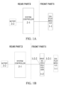
- FIG. 1A shows a block diagram of a circuit structure for a first embodiment of the present disclosure.
- Embodiments of the present disclosure provides an extended reality device, as shown in FIG. 1A , comprising: a front part 1 and a rear part 2.
- the front part 1 comprising: a display module 1-1, which is configured to display extended reality image.
- the rear part 2 comprising: a system controller 2-1 which is connected to the display module 1-1 and configured to control operation of the display module 1-1; a battery 2-2 which is connected to the system controller 2-1 and configured to supply power to each electrical device.
- the display module 1-1 is set in the shell of front part 1
- system controller 2-1 and battery 2-2 are set in the shell of rear part 2
- the shell of front part 1 and the shell of rear part 2 are connected through a connecting shell, wherein the connecting shell is provided with a connection circuits between the electrical devices of the front part 1 and the rear part 2.
- the display module adopts an LCD (Liquid Crystal Display) module
- the system controller adopts a SOC (System on Chip) Main Processer.
- All operational data and display data of the display module 1-1 are controlled through system controller 2-1, so that various interfaces of display module 1-1 are connected to system controller 2-1, so that there are more connected circuits.
- FIG. 1B shows a block diagram of a circuit structure for a second embodiment of the present disclosure.
- the front part 1 further comprises a first microprocessor 1-2 which is provided with a display operation interface 1-2-1 and a first system control interface 1-2-2.
- the display operation interface 1-2-1 is connected to the display module 1-1, and the first microprocessor 1-2 controls operational data of the display module 1-1 through the display operation interface 1-2-1.
- the first system control interface 1-2-2 is connected to the system controller 2-1, and the system controller 2-1 controls operational data of the first microprocessor 1-2 through the first system control interface 1-2-2.
- the first microprocessor 1-2 is provided with a connection interface of a user controller (for example, a handle), connecting to the user controller through the connection interface, so that the user send a control signal through the user controller, thereby obtaining the display operation control signal through the first microprocessor 1-2 processing, sending the display operation control signal to the display module 1-1 through the display operation interface 1-2-1, so that the display module 1-1 adjusts the operational data according to the display operation control signal.
- the first microprocessor 1-2 adopts MCU (Microcontroller Unit), such as MCU2 in FIG. 1P ;
- the operational data of display module 1-1 comprises at least one of the following: brightness, clarity, color contrast, display size, resolution, the initialization data of display module 1-1 and the reset data of display module 1-1, etc.
- first microprocessor 1-2 may also be connected to the system controller 2-1 through the first system control interface 1-2-2, so that operational data of first microprocessor 1-2 can be controlled through system controller 2-1.
- the operational data of first microprocessor 1-2 comprises at least one of the following: memory, sleep signal, power supply signal, etc.
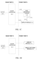
- FIG. 1C shows a block diagram of a circuit structure for a third embodiment of the present disclosure.
- FIG. 1P is a diagram of a circuit structure for the extended reality device of a specific embodiment in the present disclosure.
- the display module 1-1 is provided with a display control interface 1-1-1 and a display transport interface 1-1-2.
- the display control interface 1-1-1 is connected to the display operation interface 1-2-1 of the first microprocessor 1-2, the first microprocessor 1-2 performs data communication with the display control interface 1-1-1 through the display operation interface 1-2-1 and controls the operational data of the display module 1-1.
- the display transport interface 1-1-2 is connected to the system controller 2-1, the system controller 2-1 sends a display data through the display transport interface 1-1-2 for the display module 1-1 to display the display data.
- the first microprocessor 1-2 is used to control operational data of the display module 1-1
- the system controller 2-1 is used to send the display data to display module 1-1
- the display module 1-1 converts the display data into an extended reality image to display for users to view.
- system controller 2-1 and the first microprocessor 1-2 are used to control the display module 1-1 respectively, which can reduce the number of connection circuits between the display module 1-1 and the system controller 2-1, and at the same time make the display of the display module 1-1 and accuracy and effect of operation control are better.
- FIG. 1D shows a block diagram of a circuit structure for a fourth embodiment of the present disclosure.
- the front part 1 further comprises: an image capturing module 1-3 connected to the system controller 2-1 and configured to be controlled by the system controller 2-1 to capture image information.
- the image capturing module 1-3 may also be configured in the front part 1 of the extended reality device.
- the image capturing module 1-3 may control the image capture through the system controller 2-1, and send the captured image information to the system controller 2-1 to transmit, store or send it to the display module 1-1 for display.
- the image capturing module 1-3 may be added to the extended reality device, setting the image capturing module 1-3 in the front part 1, which can effectively ensure image capturing effect of the image capturing module 1-3.
- all operational data and image capturing data of the image capturing module 1-3 are controlled or received and processed through the system controller 2-1, so that various interfaces of the image capturing module 1-3 are connected to the system controller 2-1, so that there are more connected circuits.
- the image capturing module 1-3 and the first microprocessor 1-2 may be connected, operational data of the image capturing module 1-3 is controlled through the first microprocessor 1-2, so that the circuits for connecting the image capturing module 1-3 of the front part 1 and the system controller 2-1 of the rear part 2 can be effectively reduced.
- the operational data of the image capturing module 1-3 and the display module 1-1 need to be controlled by the first microprocessor 1-2, so that the first microprocessor 1-2 will process a larger amount of data, errors or freezes may occur.
- FIG. 1E shows a block diagram of a circuit structure for a fifth embodiment of the present disclosure.
- the front part 1 further comprises: a second microprocessor 1-4, which is provided with an image capturing operation interface 1-4-1 and a second system control interface 1-4-2.
- the image capturing operation interface 1-4-1 is connected to the image capturing module 1-3, and the second microprocessor 1-4 controls operational data of the image capturing module 1-3 through the image capturing operation interface 1-4-1.
- the second system control interface 1-4-2 is connected to the system controller 2-1, and the system controller 2-1 controls operational data of the second microprocessor 1-4 through the second system control interface 1-4-2.
- the second microprocessor 1-4 unit may also be connected to the first microprocessor 1-2, the first microprocessor 1-2 will send received control signal about the image capturing module 1-3 sent by the user to the second microprocessor 1-4. So that the second microprocessor 1-4 can control the operational data of the image capturing module 1-3.
- the second microprocessor 1-4 adopts MCU, such as MCU1 in FIG. 1P ; the operational data of image capturing module 1-3 comprises at least one of the following: size enlargement, size reduction, image capture time, image capture mode, image capture reset data, etc.
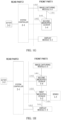
- FIG. 1F shows a block diagram of a circuit structure for a sixth embodiment of the present disclosure.
- the first microprocessor 1-2 is connected to the system controller 2-1 through the second microprocessor 1-4.
- the system controller 2-1 can send the operation control information to the first microprocessor 1-2 through the second microprocessor 1-4, thereby adjust the operational data of the first microprocessor 1-2.
- the operational data of the second microprocessor 1-4 is controlled through the system controller 2-1.
- the operational data of the second microprocessor 1-4 comprises at least one of the following: a memory, a sleep signal, a power supply signal, etc.
- the second microprocessor 1-4 is added to the front part 1 to control the operation of the image capturing module 1-3, so that can effectively ensure the operation control effect of the image capturing module 1-3, it can also effectively reduce the number of connection circuits between the image capturing module 1-3 and the system controller 2-1 at the same time, thereby makes the extended reality device easier to manufacture and reduces manufacturing costs.
- FIG. 1G shows a block diagram of a circuit structure for a seventh embodiment of the present disclosure.
- the image capturing module 1-3 is provided with a capturing control interface 1-3-1 and an image transport interface 1-3-2.
- the capturing control interface 1-3-1 is connected to the image capturing operation interface of the second microprocessor 1-4, the second microprocessor 1-4 performs data communication with the capturing control interface 1-3-1 through the image capturing operation interface 1-4-1 and controls operational data of the image capturing module 1-3.
- the image transport interface 1-3-2 is connected to the system controller 2-1, the system controller 2-1 receives image information captured by the image capturing module 1-3 through the image transport interface 1-3-2.
- the second microprocessor 1-4 is used to control the operational data of the image capturing module 1-3
- system controller 2-1 is used to receive image information captured by the image capturing module 1-3. Then the system controller 2-1 processes the image information into display data and sends it to the display module 1-1, the display module 1-1 converts the display data into an extended reality image to display for the user to view.
- the system controller 2-1 and the second microprocessor 1-4 are used to jointly control the image capturing module 1-3, which can reduce the number of connection circuits between the image capturing module 1-3 and the system controller 2-1, so that the operation control effect of the image capturing module 1-3 is better.
- the image capturing module 1-3 may also connected to the first microprocessor 1-2, the first microprocessor 1-2 will obtain an overall control signal (for example, sleep signal) of each electrical device of the front part 1 and send the overall control signal to each electrical device connected to the first microprocessor 1-2 (comprising the image capturing module 1-3).
- an overall control signal for example, sleep signal
- the image capturing module 1-3 comprises at least one of the following: a tracking camera, a depth camera, or a perspective camera.
- the tracking camera is a 6DOF (degree of freedom) camera used to track specific graphics
- the depth camera is a TOF (time of flight) camera used to capture depth information of images
- the perspective camera is an RGB (Red Green Blue, red, green and blue pixel) VST (video see through, perspective) camera used to capture perspective images of surrounding environment.
- the tracking camera, the depth camera and the perspective camera are provided with the corresponding capturing control interface 1-3-1 and the image transport interface 1-3-2, connection method of each camera to the second microprocessor 1-4 and the system controller 2-1 is the same as the above connection method of the image capturing module 1-3 and will not be described again here.
- FIG. 1H shows a block diagram of a circuit structure for an eighth embodiment of the present disclosure.
- FIG. 1I shows a block diagram of a circuit structure for a ninth embodiment of the present disclosure.
- the front part 1 further comprises: a sensor 1-5 which is connected to the first microprocessor 1-2 or the second microprocessor 1-4 and configured to control operational data of the sensor 1-5 through the first microprocessor 1-2 or the second microprocessor 1-4.
- the first microprocessor 1-2 may be used to control the operation of the sensor 1-5
- the second microprocessor 1-4 may also be used to control the operation of the sensor 1-5.
- the specific operation process comprises: the first microprocessor 1-2 or the second microprocessor 1-4 sends a control signal for the sensor 1-5 to control the sensor 1-5 to start and capture sensing information, the sensor 1-5 sends a captured sensing information to the first microprocessor 1-2 or the second microprocessor 1-4, so that the first microprocessor 1-2 or the second microprocessor 1-4 processes the sensing information.
- the senor 1-5 comprising at least one of the following: a temperature sensor, a humidity sensor, a displacement sensor, a speed sensor, a brightness sensor, a sound sensor, and the like.
- the second microprocessor 1-4 since the amount of data that the first microprocessor 1-2 needs to process is relatively large, it is preferred to use the second microprocessor 1-4 to control the operation of the sensor 1-5 (as shown in FIG. 1I and FIG. 1P ).
- FIG. 1J shows a block diagram of a circuit structure for a tenth embodiment of the present disclosure.
- the front part 1 further comprises: an audio module 1-6 which is connected to the first microprocessor 1-2 or the second microprocessor 1-4 and configured to controlled by the first microprocessor 1-2 or the second microprocessor 1-4 to control operational data of the audio module 1-6.
- the first microprocessor 1-2 may be used to control the operation of audio module 1-6
- the second microprocessor 1-4 may also be used to control the operation of audio module 1-6.
- the specific operation process comprises: the first microprocessor 1-2 or the second microprocessor 1-4 sending a control signal for the audio module 1-6 to control the operational data of the audio module 1-6.
- the operational data of the audio module 1-6 comprises at least one of the following: volume, timbre, playback mode and playback track switching, etc.
- the first microprocessor 1-2 is mainly responsible for the overall control of each electrical device of the front part 1 (such as the sleep signal received from the user), and many of the controls of the audio module 1-6 are controlled according to user's instructions.
- the first microprocessor 1-2 is provided with an interface for receiving the user instructions, therefore, in order to ensure control effect of the audio module 1-6, it is preferred to use the first microprocessor 1-2 to control the operation of the audio module 1-6 (as shown in FIG. 1J and FIG. 1P ).
- FIG. 1L is a block diagram of a circuit connection for the audio module 1-6 in a twelfth embodiment of the present disclosure.
- the audio module 1-6 is provided with an audio control interface 1-6-1 and an audio transport interface 1-6-2.
- the audio control interface 1-6-1 is connected to the first microprocessor 1-2 or the second microprocessor 1-4, and the first microprocessor 1-2 or the second microprocessor 1-4 performs data communication with the audio module 1-6 through the audio control interface 1-6-1 and controls the operational data of the audio module 1-6.
- the audio transport interface 1-6-2 is connected to the system controller 2-1, and the system controller 2-1 performs audio data transmission with the audio module 1-6 through the audio transport interface 1-6-2.
- the first microprocessor 1-2 or the second microprocessor 1-4 is used to control the operational data of audio module 1-6
- the system controller 2-1 is used to send the audio data to the audio module 1-6 and controls the audio module 1-6 to play the audio data through the operational data of the audio module 1-6 fed back by the first microprocessor 1-2 or the second microprocessor 1-4.
- the audio module 1-6 sends the captured audio data to the system controller 2-1 through the audio transport interface 1-6-2 for processing.
- the audio module 1-6 comprises: Digital MIC (Microphone) for capturing external sounds and Audio PA (audio player) for playing audio Data, as shown in FIG. 1P .
- the first microprocessor 1-2/the second microprocessor 1-4 is used in combination with the system controller 2-1 to jointly control the audio module 1-6 to play audio, which can reduce the number of connection circuits between the audio module 1-6 and the system controller 2-1, so that the operation control effect of audio module 1-6 is better.
- FIG. 1M shows a block diagram of a circuit structure for a thirteenth embodiment of the present disclosure.
- the rear part 2 further comprises a battery management module 2-3 through which the battery 2-2 is connected to the system controller 2-1, the battery management module 2-3 manages and controls the battery 2-2 according to a battery management signal sent from the system controller 2-1.
- the battery management module 2-3 controls data communication with the system controller 2-1 through a SPMI interface (System Power Management Interface, system power management interface).
- the battery management module 2-3 sends some data (for example, power) of the battery 2-2 to the system controller 2-1 through an INT (interface) interface.
- the system controller 2-1 may also send a reset signal to the battery management module 2-3 through a RESET interface, so that the battery management module 2-3 can manage the battery 2-2 to complete the reset operation based on the reset signal.
- the rear part 2 further comprises: a wireless communication module 2-4 connected to the system controller 2-1.
- the system controller 2-1 is used to control operational data of the wireless communication module 2-4.
- the wireless communication module 2-4 comprises at least one of the following: Bluetooth module, WIFI module, ZigBee module, etc. Through the wireless communication module2-4, it can receive wirelessly sent data and send the received data to the system controller 2-1 for processing; it can also send the data sent by the system controller 2-1 to the corresponding receiver wirelessly.
- the extended reality device has more comprehensive functions, and can perform wireless communication with other devices based on the wireless communication module 2-4, making it convenient for users to use.
- FIG. 1O shows a block diagram of a circuit structure for a fifteenth embodiment of the present disclosure.
- the rear part 2 further comprises: an external device interface 2-5 which is connected to the system controller 2-1 and used to connect to an external electrical device.
- this embodiment proposes a control method for an extended reality device, which is applied to the extended reality device described in each of the above embodiments.
- the extended reality device comprises: a front part and a rear part.
- FIG. 2 shows a flowchart of the control method of the extended reality device of embodiments of the present disclosure.
- the method comprises: Step 201: supplying power to a system controller configured in the rear part and a display module configured in the front part using a battery configured in the rear part.
- setting the display module in the front part setting the system controller and the battery in the rear part, supplying power to the overall electrical device using the battery, and controlling the display module through the system controller, so that the display module can perform extended reality display in the front part.
- the method of embodiment of the present disclosure can be executed by a single device, such as a computer or server, etc.
- the method of the embodiment can also be applied in a distributed scenario and completed by a plurality of devices cooperating with each other.
- one of the multiple devices may only execute one or more steps in the method of embodiment of the present disclosure, and the plurality of devices will interact with each other to complete the method.
Landscapes
- Engineering & Computer Science (AREA)
- Computer Hardware Design (AREA)
- Theoretical Computer Science (AREA)
- Physics & Mathematics (AREA)
- General Physics & Mathematics (AREA)
- General Engineering & Computer Science (AREA)
- Human Computer Interaction (AREA)
- Optics & Photonics (AREA)
- Computer Graphics (AREA)
- Software Systems (AREA)
- Computer Networks & Wireless Communication (AREA)
- Power Engineering (AREA)
- Processing Or Creating Images (AREA)
- Power Sources (AREA)
Applications Claiming Priority (1)
| Application Number | Priority Date | Filing Date | Title |
|---|---|---|---|
| CN202310266147.4A CN118642271A (zh) | 2023-03-13 | 2023-03-13 | 扩展现实设备及其控制方法 |
Publications (1)
| Publication Number | Publication Date |
|---|---|
| EP4432047A1 true EP4432047A1 (de) | 2024-09-18 |
Family
ID=90365617
Family Applications (1)
| Application Number | Title | Priority Date | Filing Date |
|---|---|---|---|
| EP24163359.3A Pending EP4432047A1 (de) | 2023-03-13 | 2024-03-13 | Vorrichtung für erweiterte realität und steuerungsverfahren dafür |
Country Status (3)
| Country | Link |
|---|---|
| US (1) | US12596261B2 (de) |
| EP (1) | EP4432047A1 (de) |
| CN (1) | CN118642271A (de) |
Citations (5)
| Publication number | Priority date | Publication date | Assignee | Title |
|---|---|---|---|---|
| US20120268433A1 (en) * | 2011-04-25 | 2012-10-25 | Kyocera Corporation | Head-mounted display |
| WO2022055118A1 (ko) * | 2020-09-08 | 2022-03-17 | 삼성전자 주식회사 | 스피커 모듈을 포함하는 웨어러블 전자 장치 |
| US20220260832A1 (en) * | 2021-02-18 | 2022-08-18 | Samsung Electronics Co., Ltd. | Wearable electronic device |
| US20220326772A1 (en) * | 2017-04-26 | 2022-10-13 | Cognixion Corporation | Brain computer interface for augmented reality |
| WO2022255682A1 (ko) * | 2021-06-02 | 2022-12-08 | 삼성전자 주식회사 | 웨어러블 전자 장치 및 그의 파워 패스 제어 방법 |
Family Cites Families (1)
| Publication number | Priority date | Publication date | Assignee | Title |
|---|---|---|---|---|
| CN108333772A (zh) | 2018-04-02 | 2018-07-27 | 佛山市博思尼智能科技有限公司 | 一种vr一体机 |
-
2023
- 2023-03-13 CN CN202310266147.4A patent/CN118642271A/zh active Pending
-
2024
- 2024-03-13 US US18/604,055 patent/US12596261B2/en active Active
- 2024-03-13 EP EP24163359.3A patent/EP4432047A1/de active Pending
Patent Citations (7)
| Publication number | Priority date | Publication date | Assignee | Title |
|---|---|---|---|---|
| US20120268433A1 (en) * | 2011-04-25 | 2012-10-25 | Kyocera Corporation | Head-mounted display |
| US20220326772A1 (en) * | 2017-04-26 | 2022-10-13 | Cognixion Corporation | Brain computer interface for augmented reality |
| WO2022055118A1 (ko) * | 2020-09-08 | 2022-03-17 | 삼성전자 주식회사 | 스피커 모듈을 포함하는 웨어러블 전자 장치 |
| US20230204965A1 (en) * | 2020-09-08 | 2023-06-29 | Samsung Electronics Co., Ltd. | Wearable electronic device comprising speaker module |
| US20220260832A1 (en) * | 2021-02-18 | 2022-08-18 | Samsung Electronics Co., Ltd. | Wearable electronic device |
| WO2022255682A1 (ko) * | 2021-06-02 | 2022-12-08 | 삼성전자 주식회사 | 웨어러블 전자 장치 및 그의 파워 패스 제어 방법 |
| US20240103289A1 (en) * | 2021-06-02 | 2024-03-28 | Samsung Electronics Co., Ltd. | Wearable electronic device and method for controlling power path thereof |
Also Published As
| Publication number | Publication date |
|---|---|
| CN118642271A (zh) | 2024-09-13 |
| US12596261B2 (en) | 2026-04-07 |
| US20240310643A1 (en) | 2024-09-19 |
Similar Documents
| Publication | Publication Date | Title |
|---|---|---|
| US11899212B2 (en) | Image display method and device for head mounted display | |
| US11106307B2 (en) | Method for low power driving of display and electronic device for performing same | |
| US9497358B2 (en) | Video latency reduction | |
| CN104282286B (zh) | 根据应用场景调整智能移动终端显示刷新率的方法及系统 | |
| CN103959200B (zh) | 自适应图像子系统功率和性能管理 | |
| US20150195604A1 (en) | Living Room Computer | |
| CN110139028A (zh) | 一种图像处理的方法及头戴式显示设备 | |
| CN102377970B (zh) | 一种mhl数据转换系统 | |
| EP4460031A1 (de) | Bildverarbeitungsverfahren und -vorrichtung sowie elektronische vorrichtung | |
| WO2021147465A1 (zh) | 一种图像渲染方法、电子设备及系统 | |
| CN205485929U (zh) | 一种基于无线通信的分布式虚拟现实显示装置及系统 | |
| WO2022160959A1 (zh) | 息屏显示方法、终端设备及芯片 | |
| US20170054942A1 (en) | Device for playing audio and video | |
| US10656675B2 (en) | Virtual reality helmet and virtual reality system | |
| US20170055034A1 (en) | Audio and video player | |
| US20170055028A1 (en) | Device for playing audio and video | |
| EP4432047A1 (de) | Vorrichtung für erweiterte realität und steuerungsverfahren dafür | |
| US20170054939A1 (en) | Audio and video player | |
| CN114640743A (zh) | 一种界面动效的显示方法及设备 | |
| CN115309256A (zh) | 一种显示方法与电子设备 | |
| US20160259231A1 (en) | Projecting system | |
| WO2022068592A1 (zh) | 一种显示方法及电子设备 | |
| US20250182385A1 (en) | Image streaming method and device for streaming point cloud-based content | |
| CN118471086B (zh) | 柔性显示面板及其显示方法、电子设备 | |
| US10481722B2 (en) | Touch device detachably connected to display device, display device and intelligent device |
Legal Events
| Date | Code | Title | Description |
|---|---|---|---|
| PUAI | Public reference made under article 153(3) epc to a published international application that has entered the european phase |
Free format text: ORIGINAL CODE: 0009012 |
|
| STAA | Information on the status of an ep patent application or granted ep patent |
Free format text: STATUS: REQUEST FOR EXAMINATION WAS MADE |
|
| 17P | Request for examination filed |
Effective date: 20240313 |
|
| AK | Designated contracting states |
Kind code of ref document: A1 Designated state(s): AL AT BE BG CH CY CZ DE DK EE ES FI FR GB GR HR HU IE IS IT LI LT LU LV MC ME MK MT NL NO PL PT RO RS SE SI SK SM TR |
|
| STAA | Information on the status of an ep patent application or granted ep patent |
Free format text: STATUS: EXAMINATION IS IN PROGRESS |
|
| 17Q | First examination report despatched |
Effective date: 20250603 |
|
| GRAP | Despatch of communication of intention to grant a patent |
Free format text: ORIGINAL CODE: EPIDOSNIGR1 |
|
| STAA | Information on the status of an ep patent application or granted ep patent |
Free format text: STATUS: GRANT OF PATENT IS INTENDED |
|
| INTG | Intention to grant announced |
Effective date: 20260112 |