EP4432017A1 - Anzeigevorrichtung und projektor mit einem holographischen optischen element - Google Patents
Anzeigevorrichtung und projektor mit einem holographischen optischen element Download PDFInfo
- Publication number
- EP4432017A1 EP4432017A1 EP22911923.5A EP22911923A EP4432017A1 EP 4432017 A1 EP4432017 A1 EP 4432017A1 EP 22911923 A EP22911923 A EP 22911923A EP 4432017 A1 EP4432017 A1 EP 4432017A1
- Authority
- EP
- European Patent Office
- Prior art keywords
- diffracted beam
- diffracted
- image
- optical element
- projector
- Prior art date
- Legal status (The legal status is an assumption and is not a legal conclusion. Google has not performed a legal analysis and makes no representation as to the accuracy of the status listed.)
- Pending
Links
Images


Classifications
-
- G—PHYSICS
- G03—PHOTOGRAPHY; CINEMATOGRAPHY; ANALOGOUS TECHNIQUES USING WAVES OTHER THAN OPTICAL WAVES; ELECTROGRAPHY; HOLOGRAPHY
- G03B—APPARATUS OR ARRANGEMENTS FOR TAKING PHOTOGRAPHS OR FOR PROJECTING OR VIEWING THEM; APPARATUS OR ARRANGEMENTS EMPLOYING ANALOGOUS TECHNIQUES USING WAVES OTHER THAN OPTICAL WAVES; ACCESSORIES THEREFOR
- G03B21/00—Projectors or projection-type viewers; Accessories therefor
- G03B21/14—Details
- G03B21/28—Reflectors in projection beam
-
- G—PHYSICS
- G03—PHOTOGRAPHY; CINEMATOGRAPHY; ANALOGOUS TECHNIQUES USING WAVES OTHER THAN OPTICAL WAVES; ELECTROGRAPHY; HOLOGRAPHY
- G03B—APPARATUS OR ARRANGEMENTS FOR TAKING PHOTOGRAPHS OR FOR PROJECTING OR VIEWING THEM; APPARATUS OR ARRANGEMENTS EMPLOYING ANALOGOUS TECHNIQUES USING WAVES OTHER THAN OPTICAL WAVES; ACCESSORIES THEREFOR
- G03B21/00—Projectors or projection-type viewers; Accessories therefor
- G03B21/14—Details
- G03B21/142—Adjusting of projection optics
-
- G—PHYSICS
- G02—OPTICS
- G02B—OPTICAL ELEMENTS, SYSTEMS OR APPARATUS
- G02B27/00—Optical systems or apparatus not provided for by any of the groups G02B1/00 - G02B26/00, G02B30/00
- G02B27/01—Head-up displays
- G02B27/0101—Head-up displays characterised by optical features
- G02B27/0103—Head-up displays characterised by optical features comprising holographic elements
-
- G—PHYSICS
- G02—OPTICS
- G02B—OPTICAL ELEMENTS, SYSTEMS OR APPARATUS
- G02B27/00—Optical systems or apparatus not provided for by any of the groups G02B1/00 - G02B26/00, G02B30/00
- G02B27/01—Head-up displays
- G02B27/017—Head mounted
- G02B27/0172—Head mounted characterised by optical features
-
- G—PHYSICS
- G03—PHOTOGRAPHY; CINEMATOGRAPHY; ANALOGOUS TECHNIQUES USING WAVES OTHER THAN OPTICAL WAVES; ELECTROGRAPHY; HOLOGRAPHY
- G03B—APPARATUS OR ARRANGEMENTS FOR TAKING PHOTOGRAPHS OR FOR PROJECTING OR VIEWING THEM; APPARATUS OR ARRANGEMENTS EMPLOYING ANALOGOUS TECHNIQUES USING WAVES OTHER THAN OPTICAL WAVES; ACCESSORIES THEREFOR
- G03B21/00—Projectors or projection-type viewers; Accessories therefor
- G03B21/14—Details
- G03B21/20—Lamp housings
- G03B21/2066—Reflectors in illumination beam
-
- G—PHYSICS
- G03—PHOTOGRAPHY; CINEMATOGRAPHY; ANALOGOUS TECHNIQUES USING WAVES OTHER THAN OPTICAL WAVES; ELECTROGRAPHY; HOLOGRAPHY
- G03H—HOLOGRAPHIC PROCESSES OR APPARATUS
- G03H1/00—Holographic processes or apparatus using light, infrared or ultraviolet waves for obtaining holograms or for obtaining an image from them; Details peculiar thereto
- G03H1/04—Processes or apparatus for producing holograms
-
- H—ELECTRICITY
- H04—ELECTRIC COMMUNICATION TECHNIQUE
- H04N—PICTORIAL COMMUNICATION, e.g. TELEVISION
- H04N9/00—Details of colour television systems
- H04N9/12—Picture reproducers
- H04N9/31—Projection devices for colour picture display, e.g. using electronic spatial light modulators [ESLM]
- H04N9/3102—Projection devices for colour picture display, e.g. using electronic spatial light modulators [ESLM] using two-dimensional electronic spatial light modulators
- H04N9/312—Driving therefor
- H04N9/3126—Driving therefor for spatial light modulators in series
-
- H—ELECTRICITY
- H04—ELECTRIC COMMUNICATION TECHNIQUE
- H04N—PICTORIAL COMMUNICATION, e.g. TELEVISION
- H04N9/00—Details of colour television systems
- H04N9/12—Picture reproducers
- H04N9/31—Projection devices for colour picture display, e.g. using electronic spatial light modulators [ESLM]
- H04N9/3141—Constructional details thereof
- H04N9/3173—Constructional details thereof wherein the projection device is specially adapted for enhanced portability
-
- H—ELECTRICITY
- H04—ELECTRIC COMMUNICATION TECHNIQUE
- H04N—PICTORIAL COMMUNICATION, e.g. TELEVISION
- H04N9/00—Details of colour television systems
- H04N9/12—Picture reproducers
- H04N9/31—Projection devices for colour picture display, e.g. using electronic spatial light modulators [ESLM]
- H04N9/3179—Video signal processing therefor
- H04N9/3185—Geometric adjustment, e.g. keystone or convergence
-
- H—ELECTRICITY
- H04—ELECTRIC COMMUNICATION TECHNIQUE
- H04N—PICTORIAL COMMUNICATION, e.g. TELEVISION
- H04N9/00—Details of colour television systems
- H04N9/12—Picture reproducers
- H04N9/31—Projection devices for colour picture display, e.g. using electronic spatial light modulators [ESLM]
- H04N9/3179—Video signal processing therefor
- H04N9/3188—Scale or resolution adjustment
-
- G—PHYSICS
- G02—OPTICS
- G02B—OPTICAL ELEMENTS, SYSTEMS OR APPARATUS
- G02B27/00—Optical systems or apparatus not provided for by any of the groups G02B1/00 - G02B26/00, G02B30/00
- G02B27/01—Head-up displays
- G02B27/0101—Head-up displays characterised by optical features
- G02B2027/0147—Head-up displays characterised by optical features comprising a device modifying the resolution of the displayed image
-
- G—PHYSICS
- G02—OPTICS
- G02B—OPTICAL ELEMENTS, SYSTEMS OR APPARATUS
- G02B27/00—Optical systems or apparatus not provided for by any of the groups G02B1/00 - G02B26/00, G02B30/00
- G02B27/01—Head-up displays
- G02B27/017—Head mounted
- G02B27/0172—Head mounted characterised by optical features
- G02B2027/0174—Head mounted characterised by optical features holographic
-
- G—PHYSICS
- G02—OPTICS
- G02B—OPTICAL ELEMENTS, SYSTEMS OR APPARATUS
- G02B5/00—Optical elements other than lenses
- G02B5/32—Holograms used as optical elements
Definitions
- the disclosure relates to a projector and a display apparatus using a holographic optical element.
- a micro display panel using a micro light-emitting diode (LED) element may be used in an ultra-small projector by using self-emission characteristics of a micro LED element, or may be used to provide a virtual image to a display apparatus, such as a head-mounted display (HMD) for augmented reality (AR)/virtual reality (VR).
- HMD head-mounted display
- AR augmented reality
- VR virtual reality
- a holographic optical element has high diffraction efficiency, narrow band wavelength characteristics, and characteristics of being able to implement several functions with one element, and thus, is used as a coupling element in an AR device such as an HMD or used in a screen for a two-dimensional (2D)/three-dimensional (3D) display.
- a projector includes: a first display unit configured to emit a first beam corresponding to a first image; and a second display unit configured to emit a second beam corresponding to a second image.
- the projector may further include a first transmissive holographic optical element configured to separate the first beam into a first diffracted beam and a second diffracted beam and transmit the first diffracted beam and the second diffracted beam, such that pixels corresponding to the first diffracted beam and pixels corresponding to the second diffracted beam are shifted by a first distance to overlap each other, the first distance being shorter than a length of one pixel; a second transmissive holographic optical element configured to separate the second beam into a third diffracted beam and a fourth diffracted beam and transmit the third diffracted beam and the fourth diffracted beam, such that pixels corresponding to the third diffracted beam and pixels corresponding to the fourth diffracted beam are shifted by a second distance to overlap each other, the second distance being shorter than a length of
- the first transmissive holographic optical element may include: a first holographic diffractive layer configured to diffract the first beam into the first diffracted beam and the second diffracted beam; and a second holographic diffractive layer configured to diffract and transmit the first diffracted beam and the second diffracted beam in a same direction with the first distance therebetween
- the second transmissive holographic optical element may include: a third holographic diffractive layer configured to diffract the second beam into the third diffracted beam and the fourth diffracted beam; and a fourth holographic diffractive layer configured to diffract and transmit the third diffracted beam and the fourth diffracted beam in a same direction with the second distance therebetween.
- the first diffracted beam may be a zero-order diffracted beam of the first beam diffracted through the first holographic diffractive layer
- the second diffracted beam may be a first-order diffracted beam of the first beam diffracted through the first holographic diffractive layer
- the third diffracted beam may be a zero-order diffracted beam of the second beam diffracted through the third holographic diffractive layer
- the fourth diffracted beam may be a first-order diffracted beam of the second beam diffracted through the fourth holographic diffractive layer.
- the first distance is a/n, where a is the length of the one pixel in a certain direction, and n is an integer.
- the first distance and the second distance are equal to each other.
- he first distance and the second distance are a/2, where a is a diagonal length of the one pixel, and the reflective holographic optical element is configured such that, based on pixels corresponding to each other, a pixel corresponding to the third diffracted beam is shifted by a distance of a/4 in a diagonal direction with respect to a pixel corresponding to the first diffracted beam to overlap the pixel corresponding to the first diffracted beam.
- the first distance and the second distance are a/4, where a is a diagonal length of the one pixel, and the reflective holographic optical element is configured such that, based on pixels corresponding to each other, a pixel corresponding to the third diffracted beam is shifted by a distance of a/2 in a diagonal direction with respect to a pixel corresponding to the first diffracted beam to overlap the pixel corresponding to the first diffracted beam.
- the first transmissive holographic optical element may be configured such that a quantity of light of the first diffracted beam and a quantity of light of the second diffracted beam are substantially equal to each other, and the second transmissive holographic optical element may be configured such that a quantity of light of the third diffracted beam and a quantity of light of the fourth diffracted beam are substantially equal to each other.
- the first transmissive holographic optical element and the reflective holographic optical element may contact each other.
- each of the first and second display units may be a micro light-emitting display panel.
- each of the first and second display units may be a full-color display panel.
- each of the first and second transmissive holographic optical elements and the reflective holographic optical element may include holographic optical element layers corresponding to a red wavelength, a green wavelength, and a blue wavelength, respectively.
- each of the first and second display units may be a monochrome display panel.
- the first image and the second image are the same image, but may have different pixel color information.
- the projector may further include: a third display unit configured to emit a third beam corresponding to a third image; a third holographic optical element configured to separate the third beam into a fifth diffracted beam and a sixth diffracted beam and transmit the fifth diffracted beam and the sixth diffracted beam, such that pixels corresponding to the fifth diffracted beam and pixels corresponding to the sixth diffracted beam are shifted by a third distance to overlap each other, the third distance be shorter than the length of one pixel; and a second reflective holographic optical element configured to transmit the first diffracted beam, the second diffracted beam, the third diffracted beam, and the fourth diffracted beam, and diffract and reflect the fifth diffracted beam and the sixth diffracted beam in a same direction as the first diffracted beam, the second diffracted beam, the third diffracted beam, and the fourth diffracted beam, such that pixels of the first image, pixels of the second image, and pixels of the third image at least partially overlap each other.
- a third display unit configured to
- the reflective holographic optical element and the second reflective holographic optical element may be arranged apart from each other, and the second reflective holographic optical element is disposed outside a path of the second beam, between the second transmissive holographic optical element and the reflective holographic optical element.
- the reflective holographic optical element and the second reflective holographic optical element may contact each other.
- the projector may further include a correction holographic optical element disposed between the second display unit and the reflective holographic optical element, and configured to correct distortion of the third diffracted beam and the fourth diffracted beam caused by diffraction and reflection by the reflective holographic optical element.
- the projector may further include a first collimating optical system arranged on a front surface of the first display unit and a second collimating optical system arranged on a front surface of the second display unit.
- a projector may include a first display unit configured to emit a first beam corresponding to a first image and a second display unit configured to emit a second beam corresponding to a second image.
- the projector may further include a transmissive holographic optical element separating the first beam into a first diffracted beam and a second diffracted beam and transmitting the first and second diffracted beams such that pixels corresponding to the first diffracted beam and pixels corresponding to the second diffracted beam are shifted by a first distance shorter than a length of one pixel in a certain direction to overlap each other, and a reflective holographic optical element transmitting the first and second diffracted beams, and diffracting and reflecting the second beam in a same direction as the first and second diffracted beams such that the first image and the second image at least partially overlap each other.
- the projector may further include a projection lens configured to project a beam corresponding to an overlapping image created by at least partially overlapping the first image and the second image with each other.
- a projector may include a first display unit configured to emit a first beam corresponding to a first image and a second display unit configured to emit a second beam corresponding to a second image.
- the projector may further include a first transmissive holographic optical element separating the first beam into a first diffracted beam and a second diffracted beam and transmitting the first and second diffracted beams such that pixels corresponding to the first diffracted beam and pixels corresponding to the second diffracted beam are shifted by a first distance shorter than a length of one pixel in a certain direction to overlap each other, and a second transmissive holographic optical element separating the second beam into a third diffracted beam and a fourth diffracted beam and transmitting the third and fourth diffracted beams such that pixels corresponding to the third diffracted beam and pixels corresponding to the fourth diffracted beam are shifted by a second distance shorter than a length of one pixel in a certain direction to overlap each other.
- the projector may further include an image combiner including a waveguide, a first input coupler configured to combine the first and second diffracted beams into the waveguide, a second input coupler configured to combine the third and fourth diffracted beams into the waveguide, and an output coupler configured to output the first to fourth diffracted beams guided by the waveguide, and a projection lens configured to project a beam of an image combined by the image combiner.
- an image combiner including a waveguide, a first input coupler configured to combine the first and second diffracted beams into the waveguide, a second input coupler configured to combine the third and fourth diffracted beams into the waveguide, and an output coupler configured to output the first to fourth diffracted beams guided by the waveguide, and a projection lens configured to project a beam of an image combined by the image combiner.
- a display apparatus includes: a projector; and an image combiner configured to guide a beam emitted from the projector to a target area, wherein the target area is an eye motion box of a user, and the projector includes: a first display unit configured to emit a first beam corresponding to a first image; a second display unit configured to emit a second beam corresponding to a second image; a first transmissive holographic optical element configured to separate the first beam into a first diffracted beam and a second diffracted beam and transmit the first diffracted beam and the second diffracted beam, such that pixels corresponding to the first diffracted beam and pixels corresponding to the second diffracted beam are shifted by a first distance to overlap each other, the first distance being shorter than a length of one pixel; a second transmissive holographic optical element configured to separate the second beam into a third diffracted beam and a fourth diffracted beam and transmit the third diffracted beam and the fourth diffracted beam, such that pixels
- a display apparatus may include a projector, and an image combiner configured to guide a beam emitted from the projector to a target area
- the projector may include a first display unit configured to emit a first beam corresponding to a first image, a second display unit configured to emit a second beam corresponding to a second image, a transmissive holographic optical element separating the first beam into a first diffracted beam and a second diffracted beam and transmitting the first and second diffracted beams such that pixels corresponding to the first diffracted beam and pixels corresponding to the second diffracted beam are shifted by a first distance shorter than a length of one pixel in a certain direction to overlap each other, a reflective holographic optical element transmitting the first and second diffracted beams, and diffracting and reflecting the second beam in a same direction as the first and second diffracted beams such that the first image and the second image at least partially overlap each other, and a projection lens configured to project a beam corresponding to an
- a display apparatus may include a projector, and an image combiner configured to guide a beam emitted from the projector to a target area
- the projector may include a first display unit configured to emit a first beam corresponding to a first image, a second display unit configured to emit a second beam corresponding to a second image, a first transmissive holographic optical element separating the first beam into a first diffracted beam and a second diffracted beam and transmitting the first and second diffracted beams such that pixels corresponding to the first diffracted beam and pixels corresponding to the second diffracted beam are shifted by a first distance shorter than a length of one pixel in a certain direction to overlap each other, a second transmissive holographic optical element separating the second beam into a third diffracted beam and a fourth diffracted beam and transmitting the third and fourth diffracted beams such that pixels corresponding to the third diffracted beam and pixels corresponding to the fourth diffracted beam are shifted by a second
- the display apparatus may be a virtual reality device or an augmented reality device.
- a display apparatus may include a display unit configured to emit a first beam corresponding to a first image, a transmissive holographic optical element separating a first beam into the a first diffracted beam and a second diffracted beam and transmitting the first and second diffracted beams such that pixels corresponding to the first diffracted beam and pixels corresponding to the second diffracted beam are shifted by a distance shorter than a length of one pixel in a certain direction to overlap each other, and a reflective holographic optical element transmitting a beam of an external scene and diffracting and reflecting the first and second diffracted beams in the same traveling direction as the beam of the external scene to guide the beam of the external scene and diffracted beams of a first image to a target area, wherein the target area may be an eye motion box of a user.
- an augmented reality device may include a left eye element and a right eye element, corresponding to a left eye and a right eye of a user, respectively, wherein each of the left eye element and the right eye element may include a projector and an image combiner configured to guide a beam emitted from the projector to a target area, and the projector may include a first display unit configured to emit a first beam corresponding to a first image, a second display unit configured to emit a second beam corresponding to a second image, a first transmissive holographic optical element separating the first beam into a first diffracted beam and a second diffracted beam and transmitting the first and second diffracted beams such that pixels corresponding to the first diffracted beam and pixels corresponding to the second diffracted beam are shifted by a first distance shorter than a length of one pixel in a certain direction to overlap each other, a second transmissive holographic optical element separating the second beam into a third diffracted beam and a fourth diff
- a micro light-emitting diode (LED) element has excellent characteristics, that is, relatively high luminance and low power consumption, but the brightness of a micro display panel is still insufficient to be used in ultra-small projectors or head-mounted displays (HMDs).
- HMDs head-mounted displays
- PPI pixels per inch
- One or more embodiments of the disclosure provide an optical system that may be capable of simultaneously increasing the brightness and resolution of a projector.
- one or more embodiments provide an optical system that may be capable of simultaneously increasing the brightness and resolution of a display apparatus.
- FIG. 1 schematically illustrates an optical system of a projector 100 according to an embodiment of the disclosure.
- the projector 100 includes a first display unit 111, a second display unit 112, a first transmissive holographic optical element (HOE) 131, a second transmissive HOE 132, a reflective HOE 140, and a projection lens 150.
- HOE holographic optical element
- the first display unit 111 emits a first beam L1 corresponding to a first image.
- the first image may include rows and columns of first pixels.
- the second display unit 112 emits a second beam L2 corresponding to a second image.
- the second image may include rows and columns of second pixels.
- the first image and the second image may be the same image, but may have different pixel color information.
- the first and second images may be determined such that pixel color information of an overlapping image formed by the optical system of the present embodiment of the disclosure is similar to pixel color information of a target image as much as possible.
- each of the first and second display units 111 and 112 may be, but is not limited to, a self-emissive display panel emitting light autonomously.
- each of the first and second display units 111 and 112 may be a micro light-emitting display panel.
- the micro light-emitting display panel may be a panel in which LEDs form a pixel array.
- each of the first and second display units 111 and 112 may be an organic light-emitting display panel.
- each of the first and second display units 111 and 112 may be a monochrome display panel for displaying a monochrome image.
- “monochrome” may mean a primary color such as red, green, or blue, or other single colors, as well as black and white having only simple contrast.
- a first collimating lens 121 for collimating, into a parallel beam, the first beam L1 emitted from the first display unit 111 may be provided on a front surface of the first display unit 111.
- a second collimating lens 122 for collimating, into a parallel beam, the second beam L2 emitted from the second display unit 112 may be provided on a front surface of the second display unit 112.
- Each of the first and second collimating lenses 121 and 122 may be, but is not limited to, a micro lens array.
- the first transmissive HOE 131 is arranged on the front surface of the first display unit 111.
- the first collimating lens 121 may be arranged between the first display unit 111 and the first transmissive HOE 131.
- the first transmissive HOE 131 may be arranged such that the first beam L1 is vertically incident on an incident surface of the first transmissive HOE 131, but the disclosure is not limited thereto.
- the first transmissive HOE 131 separates the first beam L1 into a first diffracted beam L11 and a second diffracted beam L12 and transmits the first and second diffracted beams L11 and L12 such that pixels corresponding to the first diffracted beam L11 and pixels corresponding to the second diffracted beam L12 are shifted by a first distance shorter than a length of one pixel in a certain direction to overlap each other.
- one pixel in the certain direction may be, but is not limited to, one pixel in a diagonal direction, a column direction, or a row direction.
- the length of one pixel in the certain direction may be the maximum length among lengths of one pixel in the certain direction. For example, when the certain direction is a diagonal direction, the length of one pixel in the certain direction may mean a diagonal length of one pixel.
- pixels corresponding to the first diffracted beam L11 and pixels corresponding to the second diffracted beam L12 may be shifted by a distance shorter than a diagonal length of one pixel in a diagonal direction by the first transmissive HOE 131 to overlap each other.
- the second transmissive HOE 132 is arranged on the front surface of the second display unit 112.
- the second collimating lens 122 may be arranged between the second display unit 112 and the second transmissive HOE 132.
- the second transmissive HOE 132 may be arranged such that the second beam L2 is vertically incident on an incident surface of the second transmissive HOE 132, but the disclosure is not limited thereto.
- the second transmissive HOE 132 separates the second beam L2 into a third diffracted beam L21 and a fourth diffracted beam L22 and transmits the third and fourth diffracted beams L21 and L22 such that pixels corresponding to the third diffracted beam L21 and pixels corresponding to the fourth diffracted beam L22 are shifted by a second distance shorter than a length of one pixel in a certain direction to overlap each other.
- the second distance by which the third and fourth diffracted beams L21 and L22 are shifted may be equal to the first distance by which the first and second diffracted beams L11 and L12 are shifted, but embodiments of the disclosure are not limited thereto.
- pixels corresponding to the third diffracted beam L21 and pixels corresponding to the fourth diffracted beam L22 may be shifted by a distance shorter than a diagonal length of one pixel in a diagonal direction by the second transmissive HOE 132 to overlap each other.
- FIG. 2 schematically illustrates the first transmissive HOE 131 according to an embodiment of the disclosure.
- the first transmissive HOE 131 may include a first holographic diffractive layer 1311 and a second holographic diffractive layer 1313.
- the first holographic diffractive layer 1311 allows the incident first beam L1 to be diffracted into and transmitted as the first diffracted beam L11 and the second diffracted beam L12.
- the first diffracted beam L11 and the second diffracted beam L12 may be diffracted beams of different orders, which are diffracted through the first holographic diffractive layer 1311.
- the first diffracted beam L11 may be zero-order diffracted through the first holographic diffractive layer 1311
- the second diffracted beam L12 may be first-order diffracted through the first holographic diffractive layer 1311, but embodiments of the disclosure are not limited thereto.
- the second holographic diffractive layer 1313 allows the first and second diffracted beams L11 and L12 formed by being diffracted through the first holographic diffractive layer 1311 to be diffracted again and transmitted in the same direction.
- the first and second diffracted beams L11 and L12 may be diffracted again by the second holographic diffractive layer 1313 and emitted perpendicular to an exit surface of the second holographic diffractive layer 1313, but the disclosure is not limited thereto.
- the first transmissive HOE 131 may be configured such that the quantity of light of the first diffracted beam L11 and the quantity of the light of the second diffracted beam L12 are substantially equal to each other.
- the first holographic diffractive layer 1311 may be configured such that, in the diffraction of the first beam L1, diffraction efficiency for a diffraction order of the first diffracted beam L11 and diffraction efficiency for a diffraction order of the second diffracted beam L12 are substantially equal to each other, for example, may be configured such that each of the diffraction efficiencies is approximately 50 %.
- the first holographic diffractive layer 1311 may be configured such that, in the diffraction of the first beam L1, each of diffraction efficiency for a zero-order diffraction order and diffraction efficiency for a first-order diffraction order is approximate to 50 %, and accordingly, the first beam L1 may be separated into the first diffracted beam L11 and the second diffracted beam L12 with almost no loss of the quantity of light.
- the second holographic diffractive layer 1313 may diffract the first and second diffracted beams L11 and L12 in the same direction, and may be configured such that diffraction efficiency of the first diffracted beam L11 and diffraction efficiency of the second diffracted beam L12 are substantially equal to each other, for example, may be configured such that the first and second diffracted beams L11 and L12 are diffracted with almost no loss of the quantity of light (for example, with diffraction efficiencies of about 90 % or more).
- the first transmissive HOE 131 may separate the first beam L1 into the first diffracted beam L11 and the second diffracted beam L12 with almost no loss of the quantity of light and allow the first diffracted beam L11 and the second diffracted beam L12 to travel in the same direction.
- a transparent member 1312 may be provided to support the first holographic diffractive layer 1311 and the second holographic diffractive layer 1313.
- the transparent member 1312 may include a material that is transparent with respect to a wavelength band of the first beam L1.
- the transparent member 1312 may be arranged between the first holographic diffractive layer 1311 and the second holographic diffractive layer 1313.
- the thickness T of the first transmissive HOE 131 may be understood as a distance between the first holographic diffractive layer 1311 and the second holographic diffractive layer 1313.
- the first and second diffracted beams L11 and L12 formed by being diffracted through the first holographic diffractive layer 1311 may be apart from each other by the first distance d by passing through the transparent member 1312.
- the first holographic diffractive layer 1311 and the second holographic diffractive layer 1313 may be in contact with each other, and the transparent member 1312 may be attached to and support the incident surface of the first holographic diffractive layer 1311.
- the thickness T of the first transmissive HOE 131 may be understood as a thickness of the first holographic diffractive layer 1311.
- the first holographic diffractive layer 1311 and the second holographic diffractive layer 1313 may be in contact with each other, and the transparent member 1312 may be attached to and support the exit surface of the second holographic diffractive layer 1313.
- the thickness T of the first transmissive HOE 131 may be understood as a thickness of the first holographic diffractive layer 1311.
- the second transmissive HOE 132 may also include a third holographic diffractive layer through which the second beam L2 is diffracted into and transmitted as the third diffracted beam L21 and the fourth diffracted beam L22, and a fourth holographic diffractive layer through which the third diffracted beam L21 and the fourth diffracted beam L22 are diffracted and transmitted in the same direction with the second distance therebetween.
- the second transmissive HOE 132 may have substantially the same structure as the first transmissive HOE 131 described with reference to FIG. 2 , and thus redundant descriptions are omitted.
- the reflective HOE 140 combines the first and second diffracted beams L11 and L12 of the first image and the third and fourth diffracted beams L21 and L22 of the second image together such that pixels of the first image and pixels of the second image at least partially overlap each other.
- the reflective HOE 140 may be arranged to be adjacent to an exit surface of the first transmissive HOE 131. In an embodiment of the disclosure, the reflective HOE 140 may be arranged to be in contact with the first transmissive HOE 131. In an embodiment of the disclosure, the reflective HOE 140 and the first transmissive HOE 131 may be bonded together to form an integral optical element.
- the reflective HOE 140 may be arranged to obliquely face the second transmissive HOE 132.
- a separate optical element (for example, a correction element or a reflective member) may be arranged between the reflective HOE 140 and the second transmissive HOE 132.
- FIG. 3 schematically illustrates the reflective HOE 140 according to an embodiment of the disclosure.
- the reflective HOE 140 may include a transparent body 1401 and a reflective holographic diffractive layer 1402 attached to the transparent body 1401.
- the transparent body 1401 may be omitted.
- the transparent body 1401 and the reflective holographic diffractive layer 1402 transmit the first and second diffracted beams L11 and L12 of the first image, which are diffracted and transmitted by the first transmissive HOE 131.
- the reflective holographic diffractive layer 1402 may diffract and transmit an incident beam with almost no loss of the quantity of light (for example, with a diffraction efficiency of about 90 % or more), and may transmit a beam incident on a rear surface (that is, an opposite surface to a diffractive-reflective surface) with almost no loss of the quantity of light (for example, with a diffraction efficiency of about 90 % or more).
- the reflective holographic diffractive layer 1402 may diffract and reflect an incident beam to have a diffraction efficiency of about 90 % or more with respect to a specific diffraction order (for example, first-order diffraction), and may transmit a beam incident on a rear surface to have an efficiency of about 90 % or more with respect to a specific diffraction order (for example, zero-order diffraction).
- a specific diffraction order for example, first-order diffraction
- a specific diffraction order for example, zero-order diffraction
- the first and second diffracted beams L11 and L12 of the first image which are incident on the rear surface of the reflective holographic diffractive layer 1402, may not substantially be diffracted (in other words, may be zero-order diffracted) and may be transmitted with negligible loss of the quantity of light
- third and fourth diffracted beams L3 and L4 incident on the reflective holographic diffractive layer 1402 may be diffracted in a specific diffraction order (for example, a first order) and reflected with negligible loss of the quantity of light, thereby traveling in the same direction as the first and second diffracted beams L11 and L12.
- a distance ⁇ between the reflected third and fourth diffracted beams L3 and L4 and the transmitted first and second diffracted beams L11 and L12 may be greater than or equal to 0 and may be smaller than a length of one pixel in a certain direction.
- pixels of the first and second diffracted beams L11 and L12 and pixels of the third and fourth diffracted beams L3 and L4 are completely overlapped with each other by the reflective HOE 140, and when the distance ⁇ is greater than 0 and smaller than a length of one pixel in a certain direction, the pixels of the first and second diffracted beams L11 and L12 and the pixels of the third and fourth diffracted beams L3 and L4 are partially overlapped with each other by the reflective HOE 140.
- the projection lens 150 projects a beam of an overlapping image that is created by a partial overlap by the reflective HOE 140.
- the projection lens 150 may include a single lens or a plurality of lenses.
- FIG. 4 illustrates pixels partially overlapping each other, according to an embodiment of the disclosure.
- the first transmissive HOE 131 may shift the first diffracted beam L11 and the second diffracted beam L12 of the first beam L1 by the first distance d in a diagonal direction of one pixel such that a first pixel P1 corresponding to the first diffracted beam L11 and a second pixel P1' corresponding to the second diffracted beam L12 partially overlap each other.
- the first distance d may satisfy the following Equation 2. 0 ⁇ d ⁇ a
- a may be a length of a diagonal line of a pixel.
- a is pV2.
- an example shown in FIG. 4 is a case where d is a/2, and the second pixel P1' is shifted from the first pixel P1 by a/2 (p ⁇ 2/2 in the case of a square) in a diagonal direction.
- the first pixel P1 may be shifted from the second pixel P1'.
- the first pixel P1 and the second pixel P1' overlap each other by 1/4, based on area.
- a thickness of the first transmissive HOE 131 may be 30 ⁇ m
- the diffraction angle ⁇ 1 of the first diffracted beam L11 may be 0°(deg)
- the diffraction angle ⁇ 2 of the second diffracted beam L12 may be 0.5°(deg)
- the first distance d may be 5 ⁇ m. Therefore, when a pixel size is 7 ⁇ m*7 ⁇ m, the first pixel P1 and the second pixel P1' may partially overlap each other by 1/2 of a diagonal line in a diagonal direction.
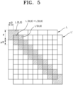
- FIG. 5 schematically illustrates that pixels of the first image are partially overlapped by the first transmissive HOE 131, according to an embodiment of the disclosure
- FIG. 6 schematically illustrates that pixels of the second image are partially overlapped by the second transmissive HOE 132, according to an embodiment of the disclosure
- FIG. 7 schematically illustrates that a first sub-overlapping image and a second sub-overlapping image are partially overlapped with each other by the reflective HOE 140, according to an embodiment of the disclosure.
- pixels corresponding to each other in a first diffraction image I 1 by the first diffracted beam L11 of the first beam L1 and a second diffraction image I 1 ' by the second diffracted beam L12 of the first beam L1 partially overlap each other to form the first sub-overlapping image.
- the first and second diffraction images I 1 and I 1 ' are the same image, for example, an image displaying a diagonal line.
- the first and second diffraction images I 1 and I 1 ' are shifted by p/2 in a row direction and by p/2 in a column direction.
- the first diffraction image I 1 and the second diffraction image I 1 ' are shifted by pV2/2 in a diagonal direction to overlap each other, and pixels corresponding to each other may overlap each other by 1/4 area.
- An area in which a pixel coordinate (0,0) of the first diffraction image I 1 and a pixel coordinate (0,0) of the second diffraction image I 1 ' overlap each other may have the sum of the respective light intensities (that is, I 1 (0.0) + I 1 '(0,0)), and thus the brightness may be increased by a factor of up to two.
- a pixel density of the first sub-overlapping image is doubled, and thus an image is displayed with greater detail and becomes clearer.
- pixels corresponding to each other in a third diffraction image I 2 by the third diffracted beam L21 of the second beam L2 and a fourth diffraction image I 2 ' by the fourth diffracted beam L22 of the second beam L2 partially overlap each other to form the second sub-overlapping image.
- the third and fourth diffraction images I 2 and I 2 ' are the same image, for example, an image displaying a diagonal line.
- Pixel color information of the third and fourth diffraction images I 2 and I 2 ' may be different from pixel color information of the first and second diffraction images I 1 and I 1 '.
- the third diffraction image I 2 and the fourth diffraction image I 2 ' may be shifted by pV2/2 in a diagonal direction by the second transmissive HOE 132 to overlap each other, pixels corresponding to each other may overlap each other by 1/4 area.
- the reflective HOE 140 combines the first sub-overlapping image and the second sub-overlapping image such that a pixel corresponding to the first sub-overlapping image and a pixel corresponding to the second sub-overlapping image are partially overlap each other to form an overlapping image.
- a pixel for example, a pixel coordinate (0,0) of the first diffraction image I 1
- a pixel for example, a pixel coordinate (0,0) of the third diffraction image I 2
- the first sub-overlapping image and the second sub-overlapping image may be shifted by pV2/4 in a diagonal direction to overlap each other.
- a pixel density of an overlapping image formed by an overlap of the first diffraction image I 1 , the second diffraction image I 1 ', the third diffraction image I 2 , and the fourth diffraction image I 2 ' may be quadrupled, and thus an image is displayed with greater detail and becomes clearer, and the brightness may be increased by a factor of up to four.
- FIGS. 8 to 10 a method of forming an overlapping image of a projector, according to an embodiment of the disclosure, will be described.
- FIG. 8 schematically illustrates that pixels of the first image are partially overlapped by the first transmissive HOE 131, according to an embodiment of the disclosure
- FIG. 9 schematically illustrates that pixels of the second image are partially overlapped by the second transmissive HOE 132, according to an embodiment of the disclosure
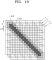
- FIG. 10 schematically illustrates that a first sub-overlapping image and a second sub-overlapping image are partially overlapped with each other by the reflective HOE 140, according to an embodiment of the disclosure.
- the method of forming the overlapping image described with reference to FIGS. 8 to 10 is substantially the same as the method of forming the overlapping image described with reference to FIGS. 5 to 7 , except for a shift size (distance) and a difference in arrangement according to the shift size, and thus differences will be mainly described.
- the first and second diffraction images I 1 and I 1 ' are shifted by p/4 in a row direction and by p/4 in a column direction to form the first sub-overlapping image.
- the first diffraction image I 1 and the second diffraction image I 1 ' are shifted by pV2/4 in a diagonal direction to overlap each other, and pixels corresponding to each other may overlap each other by 9/16 area.
- the third diffraction image I 2 and the fourth diffraction image I 2 ' are shifted by pV2/4 in a diagonal direction to overlap each other to form the second sub-overlapping image, pixels corresponding to each other may overlap each other by 9/16 area.
- the first and second sub-overlapping images are shifted by p/2 in a row direction and by p/2 in a column direction to form the overlapping image.
- a pixel for example, a pixel coordinate (0,0) of the first diffraction image I 1
- a pixel for example, a pixel coordinate (0,0) of the third diffraction image I 2
- the first sub-overlapping image and the second sub-overlapping image are shifted by pV2/2 in a diagonal direction to form the overlapping image.
- a pixel density of an overlapping image formed by an overlap of the first diffraction image I 1 , the second diffraction image I 1 ', the third diffraction image I 2 , and the fourth diffraction image I 2 ' may be quadrupled, and thus an image is displayed with greater detail and becomes clearer, and the brightness may be increased by a factor of up to four.
- FIG. 11 illustrates pixels partially overlapping each other, according to an embodiment of the disclosure.
- the first pixel P1 corresponding to the first diffracted beam L11 and the second pixel P1' corresponding to the second diffracted beam L12 may be shifted by a first distance (for example, p/2) in a column direction (a y-axis direction) of one pixel to partially overlap each other.
- a first distance for example, p/2
- a column direction a y-axis direction
- the shift in the column direction (the y-axis direction) shown in FIG. 11 is exemplary, and for example, the shift may also be carried out in a row direction (an x-axis direction) or another direction.
- FIG. 12 is a diagram illustrating an example of manufacturing a transmissive HOE, according to an embodiment of the disclosure.
- a holographic diffractive layer of the transmissive HOE may be manufactured by radiating an object beam L O and a reference beam L R on a first surface 200a of a transparent photosensitive material 200, such as photo polymer, light refractive glass, or the like, to cross each other with an angle ⁇ therebetween.
- the object beam L O and the reference beam L R are coherent beams having the same wavelength, and cause reinforcement and interference in the transparent photosensitive material 200 to form a refractive index change pattern of an interference fringe.
- the beam is diffracted at the angle ⁇ and transmitted outside a second surface 200b opposite to the first surface 200a of the transparent photosensitive material 200.
- the holographic diffractive layer may be manufactured to meet diffraction characteristics requested from the first and second transmissive HOEs 131 and 132 according to the intensity and number of the radiated object beam L O and the radiated reference beam L R .
- FIG. 12 is a diagram illustrating an example of manufacturing a reflective HOE, according to an embodiment of the disclosure.
- a holographic diffractive layer of the reflective HOE may be manufactured by radiating the object beam L O on a first surface 300a of a transparent photosensitive material 300, such as photo polymer, light refractive glass, or the like, and the reference beam L R on a second surface 300b opposite to the first surface 300a of the transparent photosensitive material 300 to cross each other with the angle ⁇ therebetween.
- a beam of the same wavelength and in the same direction as the reference beam L R is radiated on the second surface 300b of the transparent photosensitive material 300 manufactured as above, the beam is diffracted at the angle ⁇ and reflected at the second surface 300b.
- the holographic diffractive layer may be manufactured to meet diffraction characteristics requested from the reflective HOE 140 according to the intensity of the radiated object beam L O and the radiated reference beam L R .
- each of the first and second display units 111 and 112 is a monochrome display unit for displaying a monochrome image is described as an example, but embodiments of the disclosure are not limited thereto.
- each of the first and second display units 111 and 112 may be a full-color display panel for displaying a full-color image.
- each of the first and second display units 111 and 112 includes red subpixels, green subpixels, and blue subpixels on an image panel surface, and one full-color image may be implemented by a combination of a red subpixel, a green subpixel, and a blue subpixel.
- each of the first and second display units 111 and 112 may include a red display panel, a green display panel, a blue display panel, and an optical coupler for displaying a full-color image by combining a beam of a red image, a beam of a green image, and a beam of a blue image, which are respectively emitted from the red display panel, the green display panel, and the blue display panel.
- FIG. 14 schematically illustrates the configuration of a transmissive HOE 400 according to an embodiment of the disclosure.
- the transmissive HOE 400 includes a first transmissive HOE layer 401, a second transmissive HOE layer 402, and a third transmissive HOE layer 403.
- the first, second, and third transmissive HOE layers 401, 402, and 403 may be in contact with each other and stacked, or may be spaced apart from each other with a transparent spacer therebetween.
- the first, second, and third transmissive HOE layers 401, 402, and 403 correspond to a red wavelength, a blue wavelength, and a green wavelength, respectively. As described with reference to FIG.
- the HOE may be manufactured to have diffraction characteristics corresponding to a beam of a certain wavelength, and thus, the first, second, and third transmissive HOE layers 401, 402, and 403 may be manufactured to have diffraction characteristics corresponding to the red wavelength, the blue wavelength, and the green wavelength, respectively.
- the first transmissive HOE layer 401 may have diffraction characteristics in which only a red beam R is diffracted into and transmitted as first and second diffracted beams, and a green beam G and a blue beam B are transmitted substantially without diffraction.
- the second transmissive HOE layer 402 may have diffraction characteristics in which only the green beam G is diffracted into and transmitted as first and second diffracted beams, and the red beam R and the blue beam B are transmitted substantially without diffraction
- the third transmissive HOE layer 403 may have diffraction characteristics in which only the blue beam B is diffracted into and transmitted as first and second diffracted beams, and the red beam R and the green beam G are transmitted substantially without diffraction.
- the transmissive HOE 400 may be the first and second transmissive HOEs 131 and 132.
- FIG. 15 schematically illustrates the configuration of a reflective HOE 500 according to an embodiment of the disclosure.
- the reflective HOE 500 includes a first reflective HOE layer 501, a second reflective HOE layer 502, and a third reflective HOE layer 503.
- the first, second, and third reflective HOE layers 501, 502, and 503 may be in contact with each other and stacked, or may be spaced apart from each other with a transparent spacer therebetween.
- the first, second, and third reflective HOE layers 501, 502, and 503 correspond to a red wavelength, a blue wavelength, and a green wavelength, respectively. As described with reference to FIG.
- the HOE may be manufactured to have diffraction characteristics corresponding to a beam of a certain wavelength, and thus, the first, second, and third reflective HOE layers 501, 502, and 503 may be manufactured to have diffraction characteristics corresponding to the red wavelength, the blue wavelength, and the green wavelength, respectively.
- the first reflective HOE layer 501 may have diffraction characteristics in which only the red beam R is diffracted into and reflected as first and second diffracted beams, and the green beam G and the blue beam B are reflected substantially without diffraction.
- the second reflective HOE layer 502 may have diffraction characteristics in which only the green beam G is diffracted into and reflected as first and second diffracted beams, and the red beam R and the blue beam B are reflected substantially without diffraction
- the third reflective HOE layer 503 may have diffraction characteristics in which only the blue beam B is diffracted into and reflected as first and second diffracted beams, and the red beam R and the green beam G are transmitted substantially without diffraction.
- the reflective HOE 500 may be the reflective HOE 140.
- the transmissive HOE or reflective HOE corresponding to full-color is not limited to the HOE having a multilayer structure described with reference to FIGS. 14 and 15 , and an HOE having a single layer structure may also have diffraction characteristics corresponding to full-color.
- FIGS. 16 to 18 a method of forming an image of a projector, according to an embodiment of the disclosure, will be described.
- FIG. 16 is a diagram illustrating a method of forming an image by using a transmissive HOE of a projector, according to an embodiment of the disclosure.
- N low-resolution subframe images having the same pixel color information are created.
- N may be 2.
- One piece of subframe information may be determined through a known method such that, in an area where pixels overlap each other, a color information (light intensity of RGB) value of a pixel is as similar to pixel information of a target image as possible.
- Image information of a subframe is input to one display unit Src 1, and pixels of a subframe 1 are shifted by a size smaller than a diagonal length of a pixel in a diagonal direction of the pixel and combined with pixels of a shifted subframe 1' by using the transmissive HOE, thereby creating an image of a high-resolution frame.
- FIG. 17 is a diagram illustrating a method of forming an image by using a reflective HOE of a projector, according to an embodiment of the disclosure.
- N low-resolution subframe images 1 and 2 having different pixel color information are created.
- N may be 2.
- pieces of information of the subframes 1 and 2 are determined such that a color information (light intensity of RGB) value of a pixel is as similar to pixel information of a target image as possible in an overlapping area.
- a known algorithm such as a wobulation technology may be used for a method of obtaining pieces of information of the subframes 1 and 2.
- Image information of the subframes 1 and 2 is input to two display units, and pixels of the subframes 1 and 2 are shifted to each other by a size smaller than a diagonal length of a pixel in a diagonal direction of the pixel and the subframes 1 and 2 are combined by using the reflective HOE, thereby creating an image of a high-resolution frame.
- FIG. 18 is a diagram illustrating a method of forming an image by using a combination of a transmissive HOE and a reflective HOE of a projector, according to an embodiment of the disclosure.
- Information of a subframe 1 is input to a first display, and pixels of the subframe 1 are shifted and combined with pixels of the shifted subframe 1' through a first transmissive HOE, thereby creating an image of a high-resolution frame 1.
- Information of a subframe 2 is input to a second display, and pixels of the subframe 2 are shifted and combined with a shifted subframe 2' through a second transmissive HOE, thereby creating an image of a high-resolution frame 2.
- the frame 1 and the frame 2 are combined through the reflective HOE. At this time, an image may be created in two cases.
- Case 1 has twice the pixel density (2x ppi), and is where the frame 1 and the frame 2 are different images, and a value of each p/2 pixel thus created when the frame 1 and the frame 2 are combined together is set to be equal to a value of each pixel of a target image.
- Case 2 is where four times the pixel density (4x ppi) is targeted, the frame 1 and the frame 2 are different images or identical images, and a value of p/4 thus created when the frame 1 and the frame 2 are combined together is set to be equal to a value of each pixel of a target image as much as possible.
- Information of an image such as a blur phenomenon occurring when pixels overlap each other in the frame 1, may be combined with information enabling an edge portion to be highlighted in the frame 2 to make the image to be clearer.
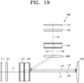
- FIG. 19 schematically illustrates an optical system of a projector according to an embodiment of the disclosure
- FIG. 20 is a diagram illustrating image distortion that occurs when there is no correction HOE
- FIG. 21 is a diagram illustrating image pre-distortion intentionally generated by a correction HOE
- FIG. 22 is a diagram illustrating an image corrected by a correction HOE.
- a projector 600 includes the first and second display units 111 and 112, the first and second transmissive HOEs 131 and 132, the reflective HOE 140, a correction element 660, and the projection lens 150.
- the projector 600 of the present embodiment of the disclosure is substantially the same as the projector of the above-described embodiment of the disclosure, except that the projector 600 further includes the correction element 660, and thus, details related to the correction element 660 will be mainly described.
- the correction element 660 is arranged on a path of the third and fourth diffracted beams L21 and L22 between the second transmissive HOE 132 and the reflective HOE 140.
- the second transmissive HOE 132 should be arranged not to interfere with paths of the first, second, third, and fourth diffracted beams L11, L12, L21, and L22 overlapping each other in the reflective HOE 140 and traveling toward the projection lens 150, the third and fourth diffracted beams L21 and L22 emitted from the second transmissive HOE 132 are obliquely incident on the reflective HOE 140.
- the reflective HOE 140 diffracts and reflects the emitted third and fourth diffracted beams L21 and L22 to travel in the same direction as the first and second diffracted beams L11 and L12, and thus, incident angles and reflection angles of the third and fourth diffracted beams L21 and L22 are different.
- the correction element 660 corrects distortion caused by the diffraction and reflection of the reflective HOE 140 by pre-distorting the third and fourth diffracted beams L21 and L22, such that a normal image may be displayed as illustrated in FIG. 22 .
- the correction element 660 may be an HOE generating image pre-distortion by diffracting the third and fourth diffracted beams L21 and L22 to correspond to the angular relationship generated by the reflective HOE 140, but the disclosure is not limited thereto.
- FIG. 23 schematically illustrates an optical system of a projector 700 according to an embodiment of the disclosure
- FIG. 24 schematically illustrates that pixels of a first image are partially overlapped by a transmissive HOE, according to an embodiment of the disclosure
- FIG. 25 schematically illustrates that a first image and a second image are partially overlapped with each other by a reflective HOE, according to an embodiment of the disclosure.
- the projector 700 includes the first and second display units 111 and 112, the first transmissive HOE 131, the reflective HOE 140, and the projection lens 150.
- the projector 700 of the present embodiment of the disclosure is substantially the same as the projectors 100 and 600, except that the projector 700 does not include the second transmissive HOE 132, and thus, differences will be mainly described.
- the first beam L1 emitted from the first display unit 111 is separated into the first diffracted beam L11 and the second diffracted beam L12 by the first transmissive HOE 131.
- the first diffraction image I 1 by the first diffracted beam L11 and the second diffraction image I 1 ' by the second diffracted beam L12 are shifted by p/3 in a row direction and by p/3 in a column direction to form a suboverlapping image, as shown in FIG. 24 .
- the first and second diffraction images I 1 and I 1 ' may be shifted by 1/3 of a diagonal length in a diagonal direction to overlap each other, and pixels corresponding to each other may overlap each other by 4/9 area.
- a second image I 2 of the second beam L2 diffracted and reflected by the reflective HOE 140 is shifted by p2/3 in a row direction and by p/23 in a column direction with respect to the first diffraction image I 1 , as shown in FIG. 25 .
- the first and second diffraction images I 1 and I 1 ' formed by the first transmissive HOE 131 and the second image I 2 are combined in the reflective HOE 140 to form an overlapping image.
- a pixel density of the overlapping image may be trebled, and thus an image is displayed with greater detail and becomes clearer, and the brightness may be increased by a factor of up to three.
- FIG. 26 schematically illustrates an optical system of a projector 800 according to an embodiment of the disclosure.
- the projector 800 includes first, second, and third display units 111, 112, and 813, first, second, and third transmissive HOEs 131, 132, and 833, the reflective HOE 140, a second reflective HOE 842, and the projection lens 150.
- the projector 800 of the present embodiment of the disclosure is substantially the same as the projectors 100, 600, and 700, except that the projector 800 further includes the third display unit 813, the third transmissive HOE 833, and the second reflective HOE 842, and thus differences will be mainly described.
- the third display unit 813 emits a third beam L3 corresponding to a third image.
- the third image may include rows and columns of third pixels.
- the third image may be the same as the first and second images respectively displayed on the first and second display units 111 and 112, but may have pixel color information different from the first and second images.
- the first to third images may be determined such that pixel color information of an overlapping image formed by the optical system of the present embodiment of the disclosure is similar to pixel color information of a target image as much as possible.
- a third collimating lens 823 for collimating, into a parallel beam, the third beam L3 emitted from the third display unit 813 may be provided on a front surface of the third display unit 813.
- the third transmissive HOE 833 is arranged on the front surface of the third display unit 813.
- the third collimating lens 823 may be arranged between the third display unit 813 and the third transmissive HOE 833.
- the third transmissive HOE 833 may be arranged such that the third beam L3 is vertically incident on an incident surface of the third transmissive HOE 833, but the disclosure is not limited thereto.
- the third transmissive HOE 833 separates the third beam L3 into a fifth diffracted beam L31 and a sixth diffracted beam L32 and transmits the fifth and sixth diffracted beams L31 and L32 such that pixels corresponding to the fifth diffracted beam L31 and pixels corresponding to the sixth diffracted beam L32 are shifted by a third distance shorter than a length of one pixel in a certain direction to overlap each other.
- the third distance by which the fifth and sixth diffracted beams L31 and L32 are shifted may be equal to the first distance by which the first and second diffracted beams L11 and L12 are shifted and/or may be equal to the second distance by which the third and fourth diffracted beams L21 and L22 are shifted, but the disclosure is not limited thereto.
- pixels corresponding to the fifth diffracted beam L31 and pixels corresponding to the sixth diffracted beam L32 may be shifted by a distance shorter than a diagonal length of one pixel in a diagonal direction to overlap each other.
- the third transmissive HOE 833 may include a fifth holographic diffractive layer through which the third beam L3 is diffracted into the fifth diffracted beam L31 and the sixth diffracted beam L32, and a sixth holographic diffractive layer through which the fifth diffracted beam L31 and the sixth diffracted beam L32 are diffracted and transmitted in the same direction with the third distance therebetween.
- the third transmissive HOE 833 may have substantially the same structure as the first transmissive HOE 131 described with reference to FIG. 2 , and thus redundant descriptions are omitted.
- the second reflective HOE 842 reflects the fifth and sixth diffracted beams L31 and L32 and transmits the first to fourth diffracted beams L11, L12, L21, and L22 of the first and second images, thereby combining the first, second, third, and fourth diffracted beams L11, L12, L21, and L22 of the first and second images and the fifth and sixth diffracted beams L31 and L32 of the third image together such that pixels of the first image, pixels of the second image, and pixels of the third image at least partially overlap each other.
- a distance between the reflected fifth and sixth diffracted beams L31 and L32 and transmitted first and second diffracted beams L11 and L12 may be greater than or equal to 0 and may be smaller than a length of one pixel in a certain direction.
- the second reflective HOE 842 may be arranged to obliquely face the third transmissive HOE 833.
- a separate optical element (for example, a correction member or a reflective member) may be arranged between the second reflective HOE 842 and the third transmissive HOE 833.
- the second reflective HOE 842 may be arranged apart from the reflective HOE 140, and the second reflective HOE 842 may be arranged outside a path of the third and fourth diffracted beams L21 and L22, between the second transmissive HOE 132 and the reflective HOE 140.
- Each of the first, second, and third display units 111, 112, and 813 may be a monochrome display unit or a full-color display unit.
- the third transmissive HOE 833 and the second reflective HOE 842 may each have a multilayer structure of HOE layers having diffraction characteristics and respectively corresponding to a red wavelength, a blue wavelength, and a green wavelength, or may each be an HOE of a multilayer structure having diffraction characteristics corresponding to full-color.
- a beam of an overlapping image formed by a combination of the first, second, third, fourth, fifth, and sixth diffracted beams L11, L12, L21, L22, L31, and L32 in the second reflective HOE 842 may be projected by the projection lens 150.
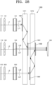
- FIG. 27 schematically illustrates an optical system of a projector 900 according to an embodiment of the disclosure.
- the projector 900 includes the first, second, and third display units 111, 112, and 813, the first, second, and third transmissive HOEs 131, 132, and 833, the reflective HOE 140, a second reflective HOE 942, and the projection lens 150.
- the projector 900 of the present embodiment of the disclosure is substantially the same as the projector 800 described with reference to FIG. 26 , except that the second reflective HOE 942 is arranged adjacent to the reflective HOE 140, and each of the first to third display units 111, 112, and 813 is limited to a monochrome display unit, and thus differences will be mainly described.
- the first, second, and third display units 111, 112, and 813 may be monochrome display units of different colors.
- the first, second, and third display units 111, 112, and 813 may be a red display unit, a green display unit, and a blue display unit, respectively.
- the first, second, and third images formed on the first, second, and third display units 111, 112, and 813 may be, for example, red, green, and blue images displaying the same image, respectively, and a full-color image may be implemented by a combination of the first to third images.
- the second reflective HOE 942 may be arranged adjacent to the reflective HOE 140. In an embodiment of the disclosure, the second reflective HOE 942 may be arranged to be in contact with the reflective HOE 140. In an embodiment of the disclosure, the second reflective HOE 942 and the reflective HOE 140 may be bonded together to form an integral optical element.
- the second reflective HOE 942 may be designed to correspond to a wavelength band of the third beam L3 emitted from the third display unit 813, thereby reflecting only the fifth and sixth diffracted beams L31 and L32 among the third, fourth, fifth, and sixth diffracted beams L21, L22, L31, and L32 incident on the same incident surface, and transmitting the third and fourth diffracted beams L21 and L22 without reflection. Also, the first, second, third, and fourth diffracted beams L11, L12, L21, and L22 incident on a surface (a rear surface) opposite to the incident surface of the second reflective HOE 942 may be transmitted substantially without diffraction.
- the reflective HOE 140 may allow pixels of the first and second diffracted beams L11 and L12 and pixels of the third and fourth diffracted beams L3 and L4 to overlap each other, and the second reflective HOE 942 may allow pixels of the first and second diffracted beams L11 and L12, pixels of the third and fourth diffracted beams L3 and L4, and pixels of the fifth and sixth diffracted beams L31 and L32 to overlap each other, which may be understood as a case where the distance ⁇ is 0 in the embodiment of the disclosure described with reference to FIG. 3 .
- an overlapping image formed by a combination of the first, second, third, fourth, fifth, and sixth diffracted beams L11, L12, L21, L22, L31, and L32 in the second reflective HOE 942 may be a full-color image by an overlap of the red image, the green image, and the blue image.
- FIG. 28 schematically illustrates an optical system of a projector 1000 according to an embodiment of the disclosure.
- the projector 1000 includes the first, second, and third display units 111, 112, and 813, the first, second, and third transmissive HOEs 131, 132, and 833, first and second waveguides 1071 and 1072, and first and second input couplers 1081 and 1082, and first and second output couplers 1091 and 1092, and the projection lens 150.
- the first, second, and third display units 111, 112, and 813 and the first, second, and third transmissive HOEs 131, 132, and 833 of the projector 1000 of the present embodiment of the disclosure are substantially the same as those of the projector 800, and thus differences will be mainly described.
- the first and second waveguides 1071 and 1072 may include a material that is transparent with respect to the first, second, and third beams L1, L2, and L3, and may have a flat plate shape.
- the first and second waveguides 1071 and 1072 may be apart from each other.
- the first and second waveguides 1071 and 1072 may include a spacer therebetween.
- the first, second, and third display units 111, 112, and 813 may be arranged in parallel on one surface of the first waveguide 1071.
- the first, second, and third transmissive HOEs 131, 132, and 833 may be arranged between the first, second, and third display units 111, 112, and 813 and the first waveguide 1071, respectively.
- the first input coupler 1081 combines the first and second diffracted beams L11 and L12 separated by the first transmissive HOE 131 into the first waveguide 1071.
- the first input coupler 1081 may be, for example, a diffractive optical element (DOE) or an HOE.
- DOE diffractive optical element
- the first input coupler 1081 may be provided on a surface of the first waveguide 1071 facing the first transmissive HOE 131, or a surface opposite to the surface.
- the second input coupler 1082 combines the fifth and sixth diffracted beams L31 and L32 separated by the third transmissive HOE 833 into the second waveguide 1072.
- the second input coupler 1082 may be, for example, a DOE or an HOE.
- the second input coupler 1082 may be provided on a surface of the second waveguide 1072 facing the third transmissive HOE 833, or a surface opposite to the surface.
- the first output coupler 1091 outputs, to the outside, the first and second diffracted beams L11 and L12 propagating in the first waveguide 1071.
- the first output coupler 1091 may be, for example, a DOE or an HOE.
- the first output coupler 1091 may be provided on a surface opposite to a surface of the first waveguide 1071 facing the second transmissive HOE 132.
- the second output coupler 1092 outputs, to the outside, the fifth and sixth diffracted beams L31 and L32 propagating in the second waveguide 1072.
- the second output coupler 1092 may be, for example, a DOE or an HOE.
- the second output coupler 1092 may be provided on a surface opposite to a surface of the second waveguide 1072 facing the second transmissive HOE 132.
- the first display unit 111 emits the first beam L1 including the first image, and the first transmissive HOE 131 diffracts and separate the first beam L1 into the first and second diffracted beams L11 and L12 such that pixels corresponding to the first diffracted beam L11 and pixels corresponding to the second diffracted beam L12 are shifted by the first distance shorter than a length of one pixel in a certain direction to overlap each other.
- the first and second diffracted beams L11 and L12 are combined in the first waveguide 1071 through the first input coupler 1081, and are totally reflected and propagate in the first waveguide 1071.
- the first and second diffracted beams L11 and L12 that are totally reflected and propagate in the first waveguide 1071 are output from the first waveguide 1071 through the first output coupler 1091.
- the first and second diffracted beams L11 and L12 output from the first waveguide 1071 pass through the second waveguide 1072.
- the second display unit 112 emits the second beam L2 including the second image, and the second transmissive HOE 132 diffracts and separates the second beam L2 into the third and fourth diffracted beams L21 and L22 such that pixels corresponding to the third diffracted beam L21 and pixels corresponding to the fourth diffracted beam L22 are shifted by the second distance shorter than a length of one pixel in a certain direction to overlap each other.
- the third and fourth diffracted beams L21 and L22 pass through the first and second waveguides 1071 and 1072.
- pixels corresponding to the first and second diffracted beams L11 and L12 and pixels corresponding to the third and fourth diffracted beams L21 and L22 may at least partially overlap each other.
- the third display unit 813 emits the third beam L3 including the third image, and the third transmissive HOE 833 diffracts and separates the third beam L3 into the fifth and sixth diffracted beams L31 and L32 such that pixels corresponding to the fifth diffracted beam L31 and pixels corresponding to the sixth diffracted beam L32 are shifted by the second distance shorter than a length of one pixel in a certain direction to overlap each other.
- the fifth and sixth diffracted beams L31 and L32 pass through the first waveguide 1071 and are combined in the second waveguide 1072 through the second input coupler 1082, and are totally reflected and propagate in the second waveguide 1072.
- the fifth and sixth diffracted beams L31 and L32 that are totally reflected and propagate in the second waveguide 1072 are output from the second waveguide 1072 through the second output coupler 1092.
- pixels corresponding to the first to fourth diffracted beams L11, L12, L21, and L22 and pixels corresponding to the fifth and sixth diffracted beams L31 and L32 may at least partially overlap each other.
- the first to sixth diffracted beams L11, L12, L21, L22, L31, and L32 may be projected by the projection lens 150 while pixels corresponding to each other are at least partially overlap each other.
- FIG. 29 schematically illustrates an optical system of a projector 1100 according to an embodiment of the disclosure.
- the projector 1100 includes the first display unit 111, first and second transmissive HOEs 1131 and 1132, and the projection lens 150.
- the first display unit 111 is substantially the same as the projector 100 described with reference to FIG. 1 .
- Each of the first and second transmissive HOEs 1131 and 1132 is substantially the same as the first transmissive HOE 131 described with reference to FIG. 2 .
- the first display unit 111 emits the first beam L1 including the first image.
- the first transmissive HOE 1131 diffracts and separates the first beam L1 into the first and second diffracted beams L11 and L12 such that pixels corresponding to the first diffracted beam L11 and pixels corresponding to the second diffracted beam L12 are shifted by the first distance shorter than a length of one pixel in a certain direction to overlap each other.
- the second transmissive HOE 1132 re-diffracts and separates the first diffracted beam L11 into first-first and first-second diffracted beams L111 and L112, such that pixels corresponding to the first-first diffracted beam L111 and pixels corresponding to the first-second diffracted beam L112 are shifted by the second distance shorter than a length of one pixel in a certain direction to overlap each other.
- the second transmissive HOE re-diffracts and separates the second diffracted beam L12 into second-first and second-second diffracted beams L121 and L122 such that pixels corresponding to the second-first diffracted beam L121 and pixels corresponding to the second-second diffracted beam L122 are shifted by the second distance to overlap each other.
- the first and second transmissive HOEs 1131 and 1132 separate the first beam L1 into the first-first and first-second diffracted beams L111 and L112 and the second-first and second-second diffracted beams L121 and L122, respectively, such that pixels corresponding to each other at least partially overlap each other.
- FIG. 30 schematically illustrates a display apparatus 1200 according to an embodiment of the disclosure.
- the display apparatus 1200 includes the first display unit 111, the first transmissive HOE 131, a waveguide 1270, an input coupler 1280, and an output coupler 1290.
- the first display unit 111 and the first transmissive HOE 131 are substantially the same as those in the above-described embodiment of the disclosure, and thus redundant descriptions are omitted.
- the first display unit 111 emits a beam Lv of a virtual image.
- the first transmissive HOE 131 diffracts and separates the beam Lv of the virtual image into the first and second diffracted beams L11 and L12 such that pixels corresponding to the first diffracted beam L11 and pixels corresponding to the second diffracted beam L12 are shifted by the first distance shorter than a length of one pixel in a certain direction to overlap each other.
- the waveguide 1270 may include a material that is transparent with respect to the beam Lv of the virtual image and a beam L O of an external scene, and may have a flat plate shape.
- the input coupler 1280 combines the first and second diffracted beams L11 and L12 separated by the first transmissive HOE 131 into the waveguide 1270.
- the input coupler 1280 may be, for example, a DOE or an HOE.
- the input coupler 1280 may be provided on a surface of the waveguide 1270 facing the first transmissive HOE 131, or a surface opposite to the surface.
- the output coupler 1290 outputs, to a target area, the first and second diffracted beams L11 and L12 propagating in the waveguide 1270.
- the output coupler 1290 may be, for example, a DOE or an HOE.
- the output coupler 1290 may be provided on a surface of the waveguide 1270 facing the target area, or a surface opposite to the surface.
- the target area may be an eye motion box which is an area where a user's eye E is located.
- the beam L O of the external scene may pass through the waveguide 1270 and travel to the target area (that is, the eye motion box).
- Both the beam Lv of the virtual image and the beam L O of the external scene may reach the eye motion box of the user, and thus the display apparatus 1200 of the present embodiment of the disclosure may be an augmented reality device in which the user may simultaneously view the user's virtual image and external scene. Pixels corresponding to each other in the beam Lv of the virtual image may be partially overlapped with each other by the first transmissive HOE 131, resulting in an increase in resolution of the display apparatus 1200 of the present embodiment of the disclosure without a decrease in brightness.
- the display apparatus 1200 may be a virtual reality device that shows only a virtual image.
- FIG. 31 schematically illustrates a display apparatus 1300 according to an embodiment of the disclosure.
- the display apparatus 1300 includes the first display unit 111, the first transmissive HOE 131, and a reflective HOE 1370.
- the first display unit 111 and the first transmissive HOE 131 are substantially the same as those in the above-described embodiment of the disclosure, and thus redundant descriptions are omitted.
- the first display unit 111 emits the beam Lv of the virtual image.
- the first transmissive HOE 131 diffracts and separates the beam Lv of the virtual image into the first and second diffracted beams L11 and L12 such that pixels corresponding to the first diffracted beam L11 and pixels corresponding to the second diffracted beam L12 are shifted by the first distance shorter than a length of one pixel in a certain direction to overlap each other.
- the reflective HOE 1370 may reflect the beam Lv of the virtual image to the target area (that is, the eye motion box) and transmit the beam L O of the external scene.
- Both the beam Lv of the virtual image and the beam L O of the external scene may reach the eye motion box of the user, and thus the display apparatus 1300 of the present embodiment of the disclosure may be an augmented reality device in which the user may simultaneously view the user's virtual image and external scene. Pixels corresponding to each other in the beam Lv of the virtual image may be partially overlapped with each other by the first transmissive HOE 131, resulting in an increase in resolution and an increase in brightness.
- the display apparatus 1300 may be a virtual reality device that shows only a virtual image.
- FIG. 32 schematically illustrates augmented reality glasses 1400 according to an embodiment of the disclosure.
- the augmented reality glasses 1400 may include an image combiner 1410 and a display engine 1420.
- the image combiner 1410 may be fixed to a frame 1490.
- the display engine 1420 may be arranged near a temple of a user's head and fixed to the frame 1490.
- the projectors 100, 600, 700, 800, 900, 1000, and 1100 of the above-described embodiment of the disclosure may be used as the display engine 1420.
- Information processing and image formation for the display engine 1420 may be performed directly by a computer of the augmented reality glasses 1400 itself, or an external electronic device, such as a smart phone, a tablet, a computer, a laptop, and all other intelligent (smart) devices, to which the augmented reality glasses 1400 are connected.
- Signal transmission between the augmented reality glasses 1400 and the external electronic device may be performed through wired communication and/or wireless communication.
- the augmented reality glasses 1400 may receive power from at least one of a built-in power source (rechargeable battery), an external device, or an external power source.
- An input-coupler 1430 of the image combiner 1410 is arranged on a surface of a waveguide (see 1270 in FIG. 30 ) facing the display engine 1420 or a rear side thereof to input, to the waveguide, a beam output from the display engine 1420.
- the input beam is guided in the waveguide toward an output-coupler (see 1290 in FIG. 30 ) and then is output to a target area through the output-coupler.
- the target area may be an eye motion box of a user.
- FIG. 32 illustrates a case where the image combiner 1410 and the display engine 1420 are each provided on both left and right sides, but the disclosure is not limited thereto.
- the image combiner 1410 and the display engine 1420 may be provided on one of the left and right sides.
- the image combiner 1410 may be provided over the entire left and right sides, and the display engine 1420 may be provided in common on the left and right sides or may be provided to correspond to each of the left and right sides.
- the augmented reality glasses 1400 are a specific example of a near-eye display apparatus. It will be obviously understood by those of ordinary skill in the art that the augmented reality glasses 1400 described with reference to FIG. 32 may be applied to display apparatuses of various forms, such as a HMD, an augmented reality helmet, and a head up display (HUD) that are worn on the head.
- a HMD head-up display
- HUD head up display
- the brightness and resolution of the projector and display apparatus using the disclosed holographic optical element may be simultaneously increased.
Landscapes
- Physics & Mathematics (AREA)
- General Physics & Mathematics (AREA)
- Engineering & Computer Science (AREA)
- Multimedia (AREA)
- Signal Processing (AREA)
- Optics & Photonics (AREA)
- Geometry (AREA)
- Diffracting Gratings Or Hologram Optical Elements (AREA)
Applications Claiming Priority (3)
| Application Number | Priority Date | Filing Date | Title |
|---|---|---|---|
| KR20210187768 | 2021-12-24 | ||
| KR1020220030320A KR20230097947A (ko) | 2021-12-24 | 2022-03-10 | 홀로그래픽 광학 소자를 이용한 프로젝터 및 디스플레이 장치 |
| PCT/KR2022/020957 WO2023121290A1 (ko) | 2021-12-24 | 2022-12-21 | 홀로그래픽 광학 소자를 이용한 프로젝터 및 디스플레이 장치 |
Publications (2)
| Publication Number | Publication Date |
|---|---|
| EP4432017A1 true EP4432017A1 (de) | 2024-09-18 |
| EP4432017A4 EP4432017A4 (de) | 2025-03-19 |
Family
ID=86897592
Family Applications (1)
| Application Number | Title | Priority Date | Filing Date |
|---|---|---|---|
| EP22911923.5A Pending EP4432017A4 (de) | 2021-12-24 | 2022-12-21 | Anzeigevorrichtung und projektor mit einem holographischen optischen element |
Country Status (2)
| Country | Link |
|---|---|
| US (1) | US12510812B2 (de) |
| EP (1) | EP4432017A4 (de) |
Family Cites Families (29)
| Publication number | Priority date | Publication date | Assignee | Title |
|---|---|---|---|---|
| US6115152A (en) | 1998-09-14 | 2000-09-05 | Digilens, Inc. | Holographic illumination system |
| JP2000111735A (ja) | 1998-10-06 | 2000-04-21 | Toppan Printing Co Ltd | ホログラフィックカラーフィルタおよびそれを用いた液晶表示装置 |
| EP1731943B1 (de) * | 2004-03-29 | 2019-02-13 | Sony Corporation | Optische einrichtung und virtuelle bildanzeigeeinrichtung |
| JP4810949B2 (ja) * | 2005-09-29 | 2011-11-09 | ソニー株式会社 | 光学装置及び画像表示装置 |
| US20070097323A1 (en) | 2005-10-31 | 2007-05-03 | Charles Otis | Electro-optical wobulator |
| GB0718706D0 (en) * | 2007-09-25 | 2007-11-07 | Creative Physics Ltd | Method and apparatus for reducing laser speckle |
| JP5266740B2 (ja) | 2007-12-10 | 2013-08-21 | セイコーエプソン株式会社 | プロジェクションシステム及びプロジェクタ |
| JP5321406B2 (ja) * | 2009-10-21 | 2013-10-23 | セイコーエプソン株式会社 | 画像表示装置 |
| KR101704738B1 (ko) | 2010-07-26 | 2017-02-08 | 한국전자통신연구원 | 고해상도 홀로그래픽 디스플레이 |
| CN107219628B (zh) | 2013-11-27 | 2020-05-01 | 奇跃公司 | 虚拟和增强现实系统与方法 |
| US9892669B2 (en) | 2014-03-18 | 2018-02-13 | Nvidia Corporation | Superresolution display using cascaded panels |
| US9344696B2 (en) * | 2014-07-29 | 2016-05-17 | Texas Instruments Incorporated | Methods and apparatus for optical display using multiple spatial light modulators for increased resolution |
| GB201500693D0 (en) | 2015-01-16 | 2015-03-04 | Wave Optics Ltd | Display System |
| WO2016124253A1 (en) | 2015-02-06 | 2016-08-11 | Optotune Ag | Optical device for enhancing resolution of an image |
| US10133075B2 (en) | 2015-05-04 | 2018-11-20 | Thalmic Labs Inc. | Systems, devices, and methods for angle- and wavelength-multiplexed holographic optical elements |
| KR101742984B1 (ko) | 2015-08-25 | 2017-06-02 | 엘지전자 주식회사 | 헤드 마운티드 디스플레이 |
| KR102266803B1 (ko) | 2017-04-06 | 2021-06-18 | 한국전자통신연구원 | 디지털 컬러 홀로그램 생성 방법 및 장치, 그리고 타일링을 이용한 디지털 컬러 홀로그래픽 디스플레이 장치 |
| KR101893590B1 (ko) | 2017-04-26 | 2018-08-31 | 인하대학교 산학협력단 | 홀로그래픽 광학 소자를 이용한 투과형 초다시점 3차원 헤드 마운트 디스플레이 장치 및 이를 이용한 디스플레이 방법 |
| US10409074B2 (en) | 2017-05-03 | 2019-09-10 | Microsoft Technology Licensing, Llc | Near-to-eye display with steerable phased arrays |
| EP3663815A4 (de) * | 2017-08-04 | 2021-05-19 | Egarim Corporation Japan | Polarisationsstrahlteiler, oberflächenlichtquellenvorrichtung und anzeigevorrichtung |
| US11698492B2 (en) | 2017-08-18 | 2023-07-11 | A9.Com, Inc. | Waveguide image combiners for augmented reality displays |
| US10942355B2 (en) * | 2018-01-22 | 2021-03-09 | Facebook Technologies, Llc | Systems, devices, and methods for tiled multi-monochromatic displays |
| KR102070606B1 (ko) | 2018-05-17 | 2020-01-29 | 주식회사 에픽옵틱스 | 회절유닛을 이용한 디스플레이 장치 |
| JP6737319B2 (ja) | 2018-11-05 | 2020-08-05 | セイコーエプソン株式会社 | プロジェクターおよびプロジェクターの制御方法 |
| KR102683759B1 (ko) * | 2018-12-18 | 2024-07-10 | 삼성전자주식회사 | 영상을 표시하는 장치, 방법 및 컴퓨터 프로그램 |
| US10866422B2 (en) | 2019-02-21 | 2020-12-15 | Microsoft Technology Licensing, Llc | Micro LED display system |
| US10554940B1 (en) | 2019-03-29 | 2020-02-04 | Razmik Ghazaryan | Method and apparatus for a variable-resolution screen |
| EP4004646A4 (de) * | 2019-07-29 | 2023-09-06 | Digilens Inc. | Verfahren und vorrichtung zum multiplizieren der bildauflösung und des sichtfeldes einer pixelierten anzeige |
| KR102843328B1 (ko) * | 2019-10-24 | 2025-08-05 | 삼성전자주식회사 | 넓은 시야창을 갖는 디스플레이 장치 |
-
2022
- 2022-12-21 EP EP22911923.5A patent/EP4432017A4/de active Pending
- 2022-12-30 US US18/091,777 patent/US12510812B2/en active Active
Also Published As
| Publication number | Publication date |
|---|---|
| EP4432017A4 (de) | 2025-03-19 |
| US12510812B2 (en) | 2025-12-30 |
| US20230205065A1 (en) | 2023-06-29 |
Similar Documents
| Publication | Publication Date | Title |
|---|---|---|
| US11624869B2 (en) | Optical expander device for providing an extended field of view | |
| US11789268B2 (en) | Optical expander device | |
| US11789261B2 (en) | Optical expander device for displaying wide color image, display device thereof, and method for outputting light and displaying an image | |
| US20220317627A1 (en) | Display device and manufacturing method thereof | |
| US12332443B2 (en) | Near-eye display device, augmented reality glasses including same, and operating method therefor | |
| JP2015102613A (ja) | 光学デバイス、及び、表示装置 | |
| US20240094456A1 (en) | Image light guide with compound in-coupling diffractive optic | |
| US12235453B2 (en) | Display apparatus for providing expanded viewing window | |
| US20240192423A1 (en) | Image display device and image display method | |
| EP4432017A1 (de) | Anzeigevorrichtung und projektor mit einem holographischen optischen element | |
| US20230036326A1 (en) | Image display apparatus | |
| US20230296883A1 (en) | Optical expander apparatus of large field of view and display apparatus | |
| CN118475884A (zh) | 使用全息光学元件的显示装置和投影仪 | |
| KR20230097947A (ko) | 홀로그래픽 광학 소자를 이용한 프로젝터 및 디스플레이 장치 | |
| JP2025510847A (ja) | 複数の波長範囲画像光ガイドシステム | |
| US12523874B2 (en) | Virtual image display apparatus | |
| US20250102806A1 (en) | Virtual image display device and optical unit | |
| US20250237869A1 (en) | Virtual-image display device and optical unit | |
| US12546946B2 (en) | Virtual image display device and optical unit | |
| US20250321425A1 (en) | Waveguide stack architecture with high red efficiency | |
| US20250076674A1 (en) | Virtual image display device and optical unit | |
| CN219916082U (zh) | 一种显示装置、抬头显示器和交通工具 | |
| JP2025075128A (ja) | 虚像表示装置及び光学ユニット | |
| US20230273435A1 (en) | Smart glasses with led projector arrays | |
| WO2024226049A1 (en) | Multiple separated field of view augmented reality waveguide system |
Legal Events
| Date | Code | Title | Description |
|---|---|---|---|
| STAA | Information on the status of an ep patent application or granted ep patent |
Free format text: STATUS: THE INTERNATIONAL PUBLICATION HAS BEEN MADE |
|
| PUAI | Public reference made under article 153(3) epc to a published international application that has entered the european phase |
Free format text: ORIGINAL CODE: 0009012 |
|
| STAA | Information on the status of an ep patent application or granted ep patent |
Free format text: STATUS: REQUEST FOR EXAMINATION WAS MADE |
|
| 17P | Request for examination filed |
Effective date: 20240613 |
|
| AK | Designated contracting states |
Kind code of ref document: A1 Designated state(s): AL AT BE BG CH CY CZ DE DK EE ES FI FR GB GR HR HU IE IS IT LI LT LU LV MC ME MK MT NL NO PL PT RO RS SE SI SK SM TR |
|
| REG | Reference to a national code |
Ref country code: DE Ref legal event code: R079 Free format text: PREVIOUS MAIN CLASS: G03H0001040000 Ipc: G02B0027010000 |
|
| A4 | Supplementary search report drawn up and despatched |
Effective date: 20250213 |
|
| RIC1 | Information provided on ipc code assigned before grant |
Ipc: H04N 9/31 20060101ALI20250207BHEP Ipc: G03H 1/04 20060101ALI20250207BHEP Ipc: G03B 21/00 20060101ALI20250207BHEP Ipc: G03B 21/28 20060101ALI20250207BHEP Ipc: G02B 5/32 20060101ALI20250207BHEP Ipc: G02B 27/01 20060101AFI20250207BHEP |
|
| DAV | Request for validation of the european patent (deleted) | ||
| DAX | Request for extension of the european patent (deleted) |