EP4431982A1 - Verfahren zur flugzeitmessung zwischen drahtlosen vorrichtungen - Google Patents
Verfahren zur flugzeitmessung zwischen drahtlosen vorrichtungen Download PDFInfo
- Publication number
- EP4431982A1 EP4431982A1 EP24163304.9A EP24163304A EP4431982A1 EP 4431982 A1 EP4431982 A1 EP 4431982A1 EP 24163304 A EP24163304 A EP 24163304A EP 4431982 A1 EP4431982 A1 EP 4431982A1
- Authority
- EP
- European Patent Office
- Prior art keywords
- mod
- tof
- twr
- way
- equation
- Prior art date
- Legal status (The legal status is an assumption and is not a legal conclusion. Google has not performed a legal analysis and makes no representation as to the accuracy of the status listed.)
- Pending
Links
Images



Classifications
-
- G—PHYSICS
- G01—MEASURING; TESTING
- G01S—RADIO DIRECTION-FINDING; RADIO NAVIGATION; DETERMINING DISTANCE OR VELOCITY BY USE OF RADIO WAVES; LOCATING OR PRESENCE-DETECTING BY USE OF THE REFLECTION OR RERADIATION OF RADIO WAVES; ANALOGOUS ARRANGEMENTS USING OTHER WAVES
- G01S13/00—Systems using the reflection or reradiation of radio waves, e.g. radar systems; Analogous systems using reflection or reradiation of waves whose nature or wavelength is irrelevant or unspecified
- G01S13/74—Systems using reradiation of radio waves, e.g. secondary radar systems; Analogous systems
- G01S13/82—Systems using reradiation of radio waves, e.g. secondary radar systems; Analogous systems wherein continuous-type signals are transmitted
- G01S13/84—Systems using reradiation of radio waves, e.g. secondary radar systems; Analogous systems wherein continuous-type signals are transmitted for distance determination by phase measurement
-
- G—PHYSICS
- G01—MEASURING; TESTING
- G01S—RADIO DIRECTION-FINDING; RADIO NAVIGATION; DETERMINING DISTANCE OR VELOCITY BY USE OF RADIO WAVES; LOCATING OR PRESENCE-DETECTING BY USE OF THE REFLECTION OR RERADIATION OF RADIO WAVES; ANALOGOUS ARRANGEMENTS USING OTHER WAVES
- G01S13/00—Systems using the reflection or reradiation of radio waves, e.g. radar systems; Analogous systems using reflection or reradiation of waves whose nature or wavelength is irrelevant or unspecified
- G01S13/74—Systems using reradiation of radio waves, e.g. secondary radar systems; Analogous systems
- G01S13/76—Systems using reradiation of radio waves, e.g. secondary radar systems; Analogous systems wherein pulse-type signals are transmitted
- G01S13/765—Systems using reradiation of radio waves, e.g. secondary radar systems; Analogous systems wherein pulse-type signals are transmitted with exchange of information between interrogator and responder
-
- G—PHYSICS
- G01—MEASURING; TESTING
- G01S—RADIO DIRECTION-FINDING; RADIO NAVIGATION; DETERMINING DISTANCE OR VELOCITY BY USE OF RADIO WAVES; LOCATING OR PRESENCE-DETECTING BY USE OF THE REFLECTION OR RERADIATION OF RADIO WAVES; ANALOGOUS ARRANGEMENTS USING OTHER WAVES
- G01S13/00—Systems using the reflection or reradiation of radio waves, e.g. radar systems; Analogous systems using reflection or reradiation of waves whose nature or wavelength is irrelevant or unspecified
- G01S13/74—Systems using reradiation of radio waves, e.g. secondary radar systems; Analogous systems
- G01S13/82—Systems using reradiation of radio waves, e.g. secondary radar systems; Analogous systems wherein continuous-type signals are transmitted
- G01S13/825—Systems using reradiation of radio waves, e.g. secondary radar systems; Analogous systems wherein continuous-type signals are transmitted with exchange of information between interrogator and responder
-
- G—PHYSICS
- G01—MEASURING; TESTING
- G01S—RADIO DIRECTION-FINDING; RADIO NAVIGATION; DETERMINING DISTANCE OR VELOCITY BY USE OF RADIO WAVES; LOCATING OR PRESENCE-DETECTING BY USE OF THE REFLECTION OR RERADIATION OF RADIO WAVES; ANALOGOUS ARRANGEMENTS USING OTHER WAVES
- G01S7/00—Details of systems according to groups G01S13/00, G01S15/00, G01S17/00
- G01S7/02—Details of systems according to groups G01S13/00, G01S15/00, G01S17/00 of systems according to group G01S13/00
- G01S7/28—Details of pulse systems
- G01S7/285—Receivers
- G01S7/288—Coherent receivers
Definitions
- the present disclosure relates to systems and methods for communication between devices and in particular to ranging exchanges between such devices.
- phase-based ranging In the classic phase-based ranging, multiple tones or carrier frequency sweeps are used.
- the receiver would, typically, lock on the transmitter carrier frequency and then measure phase of arrival for the multiple tones or the carrier frequency sweep.
- the time of flight (TOF) is then resolved from the measured phases.
- the TOF is typically measured by estimating the times of arrival and measuring the response times, i.e., without usage of any of phases of arrival. This is done without carrier frequencies necessarily being synchronized. However, the carrier frequency offset (CFO) is estimated in the reception and is compensated in the TOF estimation, either explicitly or implicitly.
- CFO carrier frequency offset
- the present disclosure shows how the phases of arrival, together with the measured response delays and CFOs, can be used in the impulse radio to provide high-precision TOF and downlink time difference of arrival (DL-TDOA) estimates.
- DL-TDOA downlink time difference of arrival
- the individual TOF and downlink time difference of arrival (DL-TDOA) estimates can be resolved up to half wavelength as in the classic phase-based ranging. The same holds for the differences between the consecutive TOFs or DL-TDOAs; these differences can be accumulated to get the estimate of the total TOF/DL-TDOA change, providing that each of these consecutive changes is below quarter wavelength.
- the estimate of the total TOF/DL-TDOA can be a sum of the initial classic impulse radio TOF/DL-TDOA estimate and the total change estimate, which is phase-based.
- the present disclosure describes methods for time-of-flight (TOF) ranging between wireless devices using single-sided two-way ranging (SS-TWR) and double-sided TWR (DS-TWR) exchanges.
- the SS-TWR method involves performing the exchange between the wireless devices and determining a first path angle, a relative carrier frequency offset of the initiator and responder devices, and a response delay of the responder.
- the method also involves determining a single SS-TWR delay and calculating a TOF delta from the determined information.
- the method involves calculating the TOF using the TOF delta with the single SS-TWR delay.
- the DS-TWR method eliminates the need for the relative carrier frequency offset estimation. Both methods enable accurate ranging between wireless devices by taking into account first path angles, and delays, which can be used in a variety of applications such as localization and tracking of objects.
- the method can be implemented on a processor of one or more of the wireless devices.
- any of the foregoing aspects individually or together, and/or various separate aspects and features as described herein, may be combined for additional advantage. Any of the various features and elements as disclosed herein may be combined with one or more other disclosed features and elements unless indicated to the contrary herein.
- Embodiments are described herein with reference to schematic illustrations of embodiments of the disclosure. As such, the actual dimensions of the layers and elements can be different, and variations from the shapes of the illustrations as a result, for example, of manufacturing techniques and/or tolerances, are expected. For example, a region illustrated or described as square or rectangular can have rounded or curved features, and regions shown as straight lines may have some irregularity. Thus, the regions illustrated in the figures are schematic and their shapes are not intended to illustrate the precise shape of a region of a device and are not intended to limit the scope of the disclosure. Additionally, sizes of structures or regions may be exaggerated relative to other structures or regions for illustrative purposes and, thus, are provided to illustrate the general structures of the present subject matter and may or may not be drawn to scale. Common elements between figures may be shown herein with common element numbers and may not be subsequently re-described.
- the method described in this disclosure is first applied in two-way ranging (TWR), specifically in single-sided TWR (SS-TWR).
- Double-sided TWR (DS-TWR), as shown in FIG. 1 , is treated as two SS-TWRs.
- the first SS-TWR consists of poll and response packets and is referred to as the SS-TWR initiator, since the initiator measures the round-trip time.
- the second SS-TWR consists of response and final packets and is referred to as the SS-TWR responder, since the responder measures the round-trip time.
- TOF time of flight
- CFO carrier frequency offset
- Responder is transmitting Response packet, and Initiator is receiving at r I .
- T F I ⁇ ⁇ I + ⁇ ⁇ RI D ⁇ R mod 1 .
- the basic phase-based SS-TWR loop 200 is shown in FIG. 2 .
- the SS-TWR loop 200 begins with an exchange between wireless devices (step 202).
- a carrier frequency offset is updated (step 204).
- a time-of-flight (TOF) using equation 7 (step 206) is calculated.
- T F k I ⁇ I + k R ⁇ R .
- T ⁇ F DS k ⁇ I ⁇ ⁇ I mod 1 + k ⁇ R ⁇ ⁇ R mod 1 .
- the basic phase-based SS-TWR loop 300 is shown in FIG. 3 .
- the DS-TWR loop 300 begins with an exchange between wireless devices (step 302).
- a time-of-flight (TOF) using either equation 10 or equation 11 (step 304) is calculated.
- the Tag In DL-TDOA, the Tag is listening to SS-TWR exchange between Initiator and Responder with the intent to calculate t D . This will be analyzed on the SS-TWR Initiator and then applied to the SS-TWR Responder as done for the t F estimation above.
- the Responder is transmitting the Response packet, and the Tag is receiving it at d R + t F + t RT .
- DL-TDOA from DS-TWR can be done without the CFO estimation, like TOF from the DS-TWR.
- mod 1 2 is used as all the normalized angles in (22) are resolvable on the interval of length one. Halving ⁇ I and ⁇ R makes the results resolvable on intervals of 1 2 and thus makes sums of ⁇ ⁇ IT + ⁇ ⁇ I 2 and ⁇ ⁇ RT + ⁇ ⁇ R 2 also resolvable on 1 2 intervals.
- ⁇ T ⁇ F I ⁇ ⁇ ⁇ I + ⁇ ⁇ ⁇ RI D ⁇ R mod 1 .
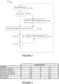
- FIG. 4 is a flowchart illustrating a method 400 for resolving consecutive TOFs employed by SS-TWR in accordance with the present disclosure.
- the method begins with an SS-TWR exchange between wireless devices (step 402).
- a processor of at least one of the wireless devices determines a first path angle, a relative carrier frequency offset of an initiator of one of the wireless devices and a responder of one of the wireless devices, and a response delay of the responder (step 404).
- a single SS-TWR exchange delay is determined (step 406).
- a next step performed by the processor is to calculate a TOF delta using the determined information from the previous step using equations (24) or (25) or (26) (step 408).
- FIG. 5 is a table of ranging results of using the method for resolving time of flights disclosed in FIG. 4 and FIG 6 .
- T ⁇ F DS ⁇ ⁇ T ⁇ F DS mod 1 .
- FIG. 6 is a flowchart illustrating a method 600 for resolving consecutive TOFs employed by DS-TWR in accordance with the present disclosure.
- the method begins with a DS-TWR exchange between wireless devices (step 602).
- a processor of at least one of the wireless devices determines a first path angle, a first path angle of an initiator of one of the wireless devices, a response delay of the responder, a first path angle of the responder, and a delay due to the initiator (step 604).
- a single DS-TWR exchange delay is determined (step 606).
- a next step performed by the processor is to calculate a TOF delta using the determined information from the previous step (step 608).
- the TOF delta is summed (step 610) with the single DS-TWR exchange delay (step 612).
- a TOF is then calculated from the results of the previous steps (step 614).
- T ⁇ D DS ⁇ ⁇ T ⁇ D DS mod 1 2 .
- the IEEE 802.15.4z high-rate pulse (HRP) physical layer (PHY) packet structure used in the measurements is shown in FIG. 7 .
- the HRP PHY consists of the two fields used for channel impulse response (CIR) and thus TOA estimation: synchronization header (SHR) and scrambled timestamp sequence (STS); the other two fields are used for data transfer: physical layer header (PHR) and physical layer service data unit (PSDU).
- CIR channel impulse response
- SHR synchronization header
- STS scrambled timestamp sequence
- PHR physical layer header
- PSDU physical layer service data unit
- the devices' crystals go through a heating-up phase and CFO changes over time, as shown in FIG. 10 .
- the results displayed in FIG. 11 are calculated according to (26) and (29) for SS-TWR and DS-TWR, respectively.
- SS-TWR is very sensitive to changes in CFO, whereas DS-TWR is completely immune.
- CFO estimate is the result of exponential moving average (EMA) filtering, as shown in FIG. 10 .
- EMA exponential moving average
- the concepts described above may be implemented in various types of wireless communication devices or user elements 10, such as mobile terminals, smart watches, tablets, computers, navigation devices, access points, and the like that support wireless communications, such as cellular, wireless local area network (WLAN), Bluetooth, near-field communications, and ultra-wideband ranging.
- the user elements 10 will generally include a control system 12, a baseband processor 14 has memory that is configured to store executable instructions for the SS-TWR method 400 ( FIG. 4 ) and/or the DS-TWR method 600 ( FIG. 6 ), transmit circuitry 16, receive circuitry 18, antenna switching circuitry 20, multiple antennas 22, and user interface circuitry 24.
- the receive circuitry 18 receives radio frequency signals including ultra-wide bandwidth signals via the antennas 22 and through the antenna switching circuitry 20 from one or more basestations and or other wireless communication devices configured like wireless communication device 10.
- a low-noise amplifier and a filter cooperate to amplify and remove broadband interference from the received signal for processing.
- Downconversion and digitization circuitry (not shown) will then downconvert the filtered, received signal to an intermediate or baseband frequency signal, which is then digitized into one or more digital streams.
- the baseband processor 14 processes the digitized received signal to extract the information or data bits conveyed in the received signal. This processing typically comprises demodulation, decoding, and error correction operations.
- the baseband processor is further configured to execute the executable instructions for the SS-TWR method 400 and/or the DS-TWR method 600 to determine range by way of time-of-flight of radio signals transmitted and received between one or more wireless communication devices configured like wireless communication device 10.
- the baseband processor 14 is generally implemented in one or more digital signal processors and application-specific integrated circuits.
- the baseband processor 14 receives digitized data, which may represent voice, data, or control information, from the control system 12, which it encodes for transmission.
- the encoded data is output to the transmit circuitry 16, where it is used by a modulator to modulate a carrier signal that is at a desired transmit frequency or frequencies, such as ultra-wideband frequencies, which span 3.1 GHz to 10.5 GHz.
- the bandwidth of ultra-wideband is greater than 500 MHz.
- a power amplifier will amplify the modulated carrier signal to a level appropriate for transmission and deliver the modulated carrier signal through the antenna switching circuitry 20 to the antennas 22.
- the antennas 22 and the replicated transmit circuitry 16 and receive circuitry 18 may provide spatial diversity. Modulation and processing details will be understood by those skilled in the art.
- a computer readable medium may include non-transitory type media such as physical storage media including storage discs and solid state devices.
- a computer readable medium may also or alternatively include transient media such as carrier signals and transmission media.
- a computer-readable storage medium is defined herein as a non-transitory memory device.
- a memory device includes memory space within a single physical storage device or memory space spread across multiple physical storage devices.
- the SS-TWR method involves performing the exchange between the wireless devices and determining a first path angle, a relative carrier frequency offset of the initiator and responder devices, and response delay of the responder. The method also involves determining a single SS-TWR delay and calculating a TOF delta from the determined information. Finally, the method involves calculating the TOF using the TOF delta with the single SS-TWR delay.
- the DS-TWR method eliminates the need for the relative carrier frequency estimation. Both methods enable accurate ranging between wireless devices by considering first path angles, and delays delay, which can be used in a variety of applications such as localization and tracking of objects.
- the method can be implemented on a processor of one or more of the wireless devices.
Landscapes
- Engineering & Computer Science (AREA)
- Radar, Positioning & Navigation (AREA)
- Remote Sensing (AREA)
- Computer Networks & Wireless Communication (AREA)
- Physics & Mathematics (AREA)
- General Physics & Mathematics (AREA)
- Mobile Radio Communication Systems (AREA)
- Radar Systems Or Details Thereof (AREA)
Applications Claiming Priority (2)
| Application Number | Priority Date | Filing Date | Title |
|---|---|---|---|
| US202363489863P | 2023-03-13 | 2023-03-13 | |
| US18/583,966 US20240310510A1 (en) | 2023-03-13 | 2024-02-22 | Method of time-of-flight ranging between wireless devices |
Publications (1)
| Publication Number | Publication Date |
|---|---|
| EP4431982A1 true EP4431982A1 (de) | 2024-09-18 |
Family
ID=90365208
Family Applications (1)
| Application Number | Title | Priority Date | Filing Date |
|---|---|---|---|
| EP24163304.9A Pending EP4431982A1 (de) | 2023-03-13 | 2024-03-13 | Verfahren zur flugzeitmessung zwischen drahtlosen vorrichtungen |
Country Status (2)
| Country | Link |
|---|---|
| US (1) | US20240310510A1 (de) |
| EP (1) | EP4431982A1 (de) |
Families Citing this family (2)
| Publication number | Priority date | Publication date | Assignee | Title |
|---|---|---|---|---|
| GB201720550D0 (en) * | 2017-12-08 | 2018-01-24 | Decawave Ltd | Ranging with simultaneous frames |
| US20250261146A1 (en) * | 2024-02-13 | 2025-08-14 | Google Llc | System for Correcting Clock Skew Between Device for Accurate Estimation of One-Way Delays |
Citations (3)
| Publication number | Priority date | Publication date | Assignee | Title |
|---|---|---|---|---|
| US9612325B2 (en) * | 2014-06-02 | 2017-04-04 | Ensco, Inc. | Unwrapping and prediction of distance and velocity measurements using carrier signals |
| US20200326403A1 (en) * | 2019-04-10 | 2020-10-15 | Stichting Imec Nederland | Method of Wireless Ranging |
| US11184048B2 (en) * | 2019-06-12 | 2021-11-23 | Stichting Imec Nederland | System and method for distance and velocity estimation in phase-based ranging |
-
2024
- 2024-02-22 US US18/583,966 patent/US20240310510A1/en active Pending
- 2024-03-13 EP EP24163304.9A patent/EP4431982A1/de active Pending
Patent Citations (3)
| Publication number | Priority date | Publication date | Assignee | Title |
|---|---|---|---|---|
| US9612325B2 (en) * | 2014-06-02 | 2017-04-04 | Ensco, Inc. | Unwrapping and prediction of distance and velocity measurements using carrier signals |
| US20200326403A1 (en) * | 2019-04-10 | 2020-10-15 | Stichting Imec Nederland | Method of Wireless Ranging |
| US11184048B2 (en) * | 2019-06-12 | 2021-11-23 | Stichting Imec Nederland | System and method for distance and velocity estimation in phase-based ranging |
Non-Patent Citations (1)
| Title |
|---|
| KRSKA JOSEF ET AL: "Utilization of Carrier-Frequency Offset Measurements in UWB TDoA Positioning with Receiving Tag", SENSORS, vol. 23, no. 5, 26 February 2023 (2023-02-26), CH, pages 2595, XP093187456, ISSN: 1424-8220, Retrieved from the Internet <URL:https://www.mdpi.com/1424-8220/23/5/2595/pdf> DOI: 10.3390/s23052595 * |
Also Published As
| Publication number | Publication date |
|---|---|
| US20240310510A1 (en) | 2024-09-19 |
Similar Documents
| Publication | Publication Date | Title |
|---|---|---|
| US12081643B2 (en) | Methods for nanosecond-scale time synchronization over a network | |
| US11909852B1 (en) | Frequency and gain calibration for time synchronization in a network | |
| US7450069B2 (en) | Ranging system and method | |
| EP4431982A1 (de) | Verfahren zur flugzeitmessung zwischen drahtlosen vorrichtungen | |
| KR102132152B1 (ko) | 무선 신호의 타이밍 및 로컬라이징 방법 및 시스템 | |
| Smaoui et al. | Single-antenna AoA estimation with UWB radios | |
| JP6876794B2 (ja) | テレグラム分割に基づく測位 | |
| KR100570315B1 (ko) | 디지털 전화망용 위치결정 시스템 | |
| US11294024B2 (en) | System, apparatus, and/or method for determining a time of flight for one or more receivers and transmitters | |
| US10505653B1 (en) | Methods and apparatus for fine timing measurement with frequency domain processing | |
| KR101836837B1 (ko) | 측위 시스템 내 시간 차이 보상 방법 및 그에 따른 측위 시스템 | |
| US9316721B2 (en) | Method and system for estimating the location of a mobile terminal | |
| WO2022119670A1 (en) | System and method for generating phase-coherent signaling when ranging between wireless communications nodes | |
| US20250012916A1 (en) | Phase difference correction method and ultra-wideband system | |
| CN109085563A (zh) | 基于软件无线电平台的wlan测距技术 | |
| EP4256373B1 (de) | System und verfahren zur erzeugung von phasenkohärenter signalisierung bei der entfernungsmessung zwischen drahtlosen kommunikationsknoten und zur berücksichtigung von phasenverschiebung dazwischen | |
| US12279226B2 (en) | Communication device and method | |
| Märzinger et al. | Time-multiplexed AoA estimation and ranging | |
| CN118642090A (zh) | 无线装置之间的飞行时间测距方法 | |
| US7327314B2 (en) | Two-way ranging between radio transceivers | |
| US11026192B2 (en) | System and method to enhance ranging resolution for localization of a LoRa sensor or device | |
| Exel | Receiver design for time‐based ranging with IEEE 802.11 b signals | |
| US20250283989A1 (en) | Methods for carrier offset estimation and phase-based tof calculation in double-sided two-way ranging | |
| Sark et al. | An approach for implementation of ranging and positioning methods on a software defined radio | |
| CN115955287A (zh) | 一种用于分布式干扰的高精度时频同步方法 |
Legal Events
| Date | Code | Title | Description |
|---|---|---|---|
| PUAI | Public reference made under article 153(3) epc to a published international application that has entered the european phase |
Free format text: ORIGINAL CODE: 0009012 |
|
| STAA | Information on the status of an ep patent application or granted ep patent |
Free format text: STATUS: THE APPLICATION HAS BEEN PUBLISHED |
|
| AK | Designated contracting states |
Kind code of ref document: A1 Designated state(s): AL AT BE BG CH CY CZ DE DK EE ES FI FR GB GR HR HU IE IS IT LI LT LU LV MC ME MK MT NL NO PL PT RO RS SE SI SK SM TR |
|
| STAA | Information on the status of an ep patent application or granted ep patent |
Free format text: STATUS: REQUEST FOR EXAMINATION WAS MADE |
|
| 17P | Request for examination filed |
Effective date: 20250318 |
|
| STAA | Information on the status of an ep patent application or granted ep patent |
Free format text: STATUS: EXAMINATION IS IN PROGRESS |
|
| 17Q | First examination report despatched |
Effective date: 20251212 |