EP4431920A1 - Schweissprüfvorrichtung - Google Patents
Schweissprüfvorrichtung Download PDFInfo
- Publication number
- EP4431920A1 EP4431920A1 EP22890487.6A EP22890487A EP4431920A1 EP 4431920 A1 EP4431920 A1 EP 4431920A1 EP 22890487 A EP22890487 A EP 22890487A EP 4431920 A1 EP4431920 A1 EP 4431920A1
- Authority
- EP
- European Patent Office
- Prior art keywords
- welding
- welding inspection
- hollow hole
- inspection method
- lens
- Prior art date
- Legal status (The legal status is an assumption and is not a legal conclusion. Google has not performed a legal analysis and makes no representation as to the accuracy of the status listed.)
- Granted
Links
Images
Classifications
-
- G—PHYSICS
- G01—MEASURING; TESTING
- G01N—INVESTIGATING OR ANALYSING MATERIALS BY DETERMINING THEIR CHEMICAL OR PHYSICAL PROPERTIES
- G01N21/00—Investigating or analysing materials by the use of optical means, i.e. using sub-millimetre waves, infrared, visible or ultraviolet light
- G01N21/84—Systems specially adapted for particular applications
- G01N21/88—Investigating the presence of flaws or contamination
-
- H—ELECTRICITY
- H04—ELECTRIC COMMUNICATION TECHNIQUE
- H04N—PICTORIAL COMMUNICATION, e.g. TELEVISION
- H04N23/00—Cameras or camera modules comprising electronic image sensors; Control thereof
- H04N23/50—Constructional details
- H04N23/555—Constructional details for picking-up images in sites, inaccessible due to their dimensions or hazardous conditions, e.g. endoscopes or borescopes
-
- B—PERFORMING OPERATIONS; TRANSPORTING
- B23—MACHINE TOOLS; METAL-WORKING NOT OTHERWISE PROVIDED FOR
- B23K—SOLDERING OR UNSOLDERING; WELDING; CLADDING OR PLATING BY SOLDERING OR WELDING; CUTTING BY APPLYING HEAT LOCALLY, e.g. FLAME CUTTING; WORKING BY LASER BEAM
- B23K31/00—Processes relevant to this subclass, specially adapted for particular articles or purposes, but not covered by any single one of main groups B23K1/00 - B23K28/00
- B23K31/12—Processes relevant to this subclass, specially adapted for particular articles or purposes, but not covered by any single one of main groups B23K1/00 - B23K28/00 relating to investigating the properties, e.g. the weldability, of materials
- B23K31/125—Weld quality monitoring
-
- G—PHYSICS
- G01—MEASURING; TESTING
- G01N—INVESTIGATING OR ANALYSING MATERIALS BY DETERMINING THEIR CHEMICAL OR PHYSICAL PROPERTIES
- G01N21/00—Investigating or analysing materials by the use of optical means, i.e. using sub-millimetre waves, infrared, visible or ultraviolet light
- G01N21/84—Systems specially adapted for particular applications
- G01N21/88—Investigating the presence of flaws or contamination
- G01N21/95—Investigating the presence of flaws or contamination characterised by the material or shape of the object to be examined
- G01N21/952—Inspecting the exterior surface of cylindrical bodies or wires
-
- G—PHYSICS
- G01—MEASURING; TESTING
- G01N—INVESTIGATING OR ANALYSING MATERIALS BY DETERMINING THEIR CHEMICAL OR PHYSICAL PROPERTIES
- G01N21/00—Investigating or analysing materials by the use of optical means, i.e. using sub-millimetre waves, infrared, visible or ultraviolet light
- G01N21/84—Systems specially adapted for particular applications
- G01N21/88—Investigating the presence of flaws or contamination
- G01N21/95—Investigating the presence of flaws or contamination characterised by the material or shape of the object to be examined
- G01N21/954—Inspecting the inner surface of hollow bodies, e.g. bores
-
- G—PHYSICS
- G02—OPTICS
- G02B—OPTICAL ELEMENTS, SYSTEMS OR APPARATUS
- G02B23/00—Telescopes, e.g. binoculars; Periscopes; Instruments for viewing the inside of hollow bodies; Viewfinders; Optical aiming or sighting devices
- G02B23/24—Instruments or systems for viewing the inside of hollow bodies, e.g. fibrescopes
- G02B23/2407—Optical details
- G02B23/2461—Illumination
-
- G—PHYSICS
- G06—COMPUTING OR CALCULATING; COUNTING
- G06T—IMAGE DATA PROCESSING OR GENERATION, IN GENERAL
- G06T7/00—Image analysis
- G06T7/0002—Inspection of images, e.g. flaw detection
- G06T7/0004—Industrial image inspection
-
- H—ELECTRICITY
- H01—ELECTRIC ELEMENTS
- H01M—PROCESSES OR MEANS, e.g. BATTERIES, FOR THE DIRECT CONVERSION OF CHEMICAL ENERGY INTO ELECTRICAL ENERGY
- H01M10/00—Secondary cells; Manufacture thereof
- H01M10/42—Methods or arrangements for servicing or maintenance of secondary cells or secondary half-cells
- H01M10/4285—Testing apparatus
-
- H—ELECTRICITY
- H01—ELECTRIC ELEMENTS
- H01M—PROCESSES OR MEANS, e.g. BATTERIES, FOR THE DIRECT CONVERSION OF CHEMICAL ENERGY INTO ELECTRICAL ENERGY
- H01M50/00—Constructional details or processes of manufacture of the non-active parts of electrochemical cells other than fuel cells, e.g. hybrid cells
- H01M50/50—Current conducting connections for cells or batteries
- H01M50/543—Terminals
- H01M50/564—Terminals characterised by their manufacturing process
- H01M50/566—Terminals characterised by their manufacturing process by welding, soldering or brazing
-
- H—ELECTRICITY
- H04—ELECTRIC COMMUNICATION TECHNIQUE
- H04N—PICTORIAL COMMUNICATION, e.g. TELEVISION
- H04N23/00—Cameras or camera modules comprising electronic image sensors; Control thereof
- H04N23/56—Cameras or camera modules comprising electronic image sensors; Control thereof provided with illuminating means
-
- B—PERFORMING OPERATIONS; TRANSPORTING
- B23—MACHINE TOOLS; METAL-WORKING NOT OTHERWISE PROVIDED FOR
- B23K—SOLDERING OR UNSOLDERING; WELDING; CLADDING OR PLATING BY SOLDERING OR WELDING; CUTTING BY APPLYING HEAT LOCALLY, e.g. FLAME CUTTING; WORKING BY LASER BEAM
- B23K2101/00—Articles made by soldering, welding or cutting
- B23K2101/36—Electric or electronic devices
-
- G—PHYSICS
- G01—MEASURING; TESTING
- G01N—INVESTIGATING OR ANALYSING MATERIALS BY DETERMINING THEIR CHEMICAL OR PHYSICAL PROPERTIES
- G01N21/00—Investigating or analysing materials by the use of optical means, i.e. using sub-millimetre waves, infrared, visible or ultraviolet light
- G01N21/84—Systems specially adapted for particular applications
- G01N21/88—Investigating the presence of flaws or contamination
- G01N21/8851—Scan or image signal processing specially adapted therefor, e.g. for scan signal adjustment, for detecting different kinds of defects, for compensating for structures, markings, edges
- G01N2021/8887—Scan or image signal processing specially adapted therefor, e.g. for scan signal adjustment, for detecting different kinds of defects, for compensating for structures, markings, edges based on image processing techniques
-
- G—PHYSICS
- G01—MEASURING; TESTING
- G01N—INVESTIGATING OR ANALYSING MATERIALS BY DETERMINING THEIR CHEMICAL OR PHYSICAL PROPERTIES
- G01N21/00—Investigating or analysing materials by the use of optical means, i.e. using sub-millimetre waves, infrared, visible or ultraviolet light
- G01N21/84—Systems specially adapted for particular applications
- G01N21/88—Investigating the presence of flaws or contamination
- G01N21/95—Investigating the presence of flaws or contamination characterised by the material or shape of the object to be examined
- G01N21/954—Inspecting the inner surface of hollow bodies, e.g. bores
- G01N2021/9542—Inspecting the inner surface of hollow bodies, e.g. bores using a probe
- G01N2021/9544—Inspecting the inner surface of hollow bodies, e.g. bores using a probe with emitter and receiver on the probe
-
- G—PHYSICS
- G06—COMPUTING OR CALCULATING; COUNTING
- G06T—IMAGE DATA PROCESSING OR GENERATION, IN GENERAL
- G06T2207/00—Indexing scheme for image analysis or image enhancement
- G06T2207/10—Image acquisition modality
- G06T2207/10068—Endoscopic image
-
- Y—GENERAL TAGGING OF NEW TECHNOLOGICAL DEVELOPMENTS; GENERAL TAGGING OF CROSS-SECTIONAL TECHNOLOGIES SPANNING OVER SEVERAL SECTIONS OF THE IPC; TECHNICAL SUBJECTS COVERED BY FORMER USPC CROSS-REFERENCE ART COLLECTIONS [XRACs] AND DIGESTS
- Y02—TECHNOLOGIES OR APPLICATIONS FOR MITIGATION OR ADAPTATION AGAINST CLIMATE CHANGE
- Y02E—REDUCTION OF GREENHOUSE GAS [GHG] EMISSIONS, RELATED TO ENERGY GENERATION, TRANSMISSION OR DISTRIBUTION
- Y02E60/00—Enabling technologies; Technologies with a potential or indirect contribution to GHG emissions mitigation
- Y02E60/10—Energy storage using batteries
-
- Y—GENERAL TAGGING OF NEW TECHNOLOGICAL DEVELOPMENTS; GENERAL TAGGING OF CROSS-SECTIONAL TECHNOLOGIES SPANNING OVER SEVERAL SECTIONS OF THE IPC; TECHNICAL SUBJECTS COVERED BY FORMER USPC CROSS-REFERENCE ART COLLECTIONS [XRACs] AND DIGESTS
- Y02—TECHNOLOGIES OR APPLICATIONS FOR MITIGATION OR ADAPTATION AGAINST CLIMATE CHANGE
- Y02P—CLIMATE CHANGE MITIGATION TECHNOLOGIES IN THE PRODUCTION OR PROCESSING OF GOODS
- Y02P70/00—Climate change mitigation technologies in the production process for final industrial or consumer products
- Y02P70/50—Manufacturing or production processes characterised by the final manufactured product
Definitions
- the present disclosure relates to a welding inspection apparatus, and in particular, an apparatus used to see a welding state in a hollow hole part of a cylindrical electrode assembly on a linear track.
- Secondary batteries are highly applicable to various product groups, and exhibit electrical properties such as high energy density and the like. Accordingly, secondary batteries are universally applied to electric vehicles (EV) or hybrid vehicles (HEV) and the like driven by an electric driving source as well as mobile devices.
- EV electric vehicles
- HEV hybrid vehicles
- Secondary batteries not only help to reduce the consumption of fossil fuels significantly but also produce no by-products after the use of their energy. Thus, secondary batteries are hailed as an alternative energy source that protect the environment and improve energy efficiency.
- Secondary batteries include a lithium-ion battery, a lithium-polymer battery, a nickelcadmium battery, a nickel-hydrogen battery, a nickel-zinc battery and the like that are currently used.
- the operating voltage of such a unit secondary battery cell i.e., a unit battery cell, is about 2.5 V to 4.5 V.
- a plurality of battery cells connects in series, to constitute a battery pack.
- a plurality of battery cells connects in parallel to constitute a battery pack, depending on the charge capacity or discharge capacity required of the battery pack.
- the number of battery cells included in the battery packs, and the electric connection form of the battery cells can vary depending on a required output voltage and/or charge and discharge capacity.
- unit secondary battery cells include a cylindrical battery cell, a prismatic battery cell, and a pouch-type battery cell.
- a separation layer as an insulator is interposed between an anode and a cathode, and the stack of electrodes and separation layer is wound to form a jelly roll-type electrode assembly, and the jelly roll-type electrode assembly is inserted into a battery can, to form a battery.
- a strip-shaped electrode tab can connect to an uncoated part of each of the anode and the cathode, and electrically connects between the electrode assembly and an electrode terminal that is exposed outward.
- a positive electrode terminal is a cap plate of a sealing body that seals an opening of a battery can
- a negative electrode terminal is a battery can.
- an anode uncoated part and a cathode uncoated part are respectively disposed at the upper end and the lower end of the jelly roll-type electrode assembly, and a current collection plate is welded to the uncoated parts, to manufacture a cylindrical battery cell (the so-called tab-less cylindrical battery cell) ensuring improvement in the efficiency of collecting current.
- a battery cell in which the electrode assembly electrically connects to the outside, in a way that a current collection plate is welded to an uncoated part of an electrode assembly, and also welded from the inside of the battery can to an electrode terminal, which is fixed to penetrate one end portion of a battery can and protrudes out of the battery can.
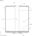
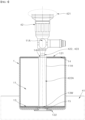
- FIG. 1 is a lateral cross-sectional view showing an uncoated part of an electrode assembly and a first current collection plate are welded, and then a first electrode terminal rivet-fixed to one end portion of a battery can and the first current collection plate are welded while a cylindrical battery cell is manufactured.
- the first current collection plate 13 is welded to a first uncoated part 111a, and the electrode assembly 11 is accommodated in the battery can 12 in a way that a second uncoated part 111b faces an open part 121 of the battery can 12.
- the first current collection plate 13 is welded to a first electrode terminal 15 in a welding portion 13W at one end portion of the hollow hole part 11H, which is rivet-fixed in a way that penetrates the bottom surface of the battery can 12,
- the welding portion 13W can be checked only through the hollow hole part 11H.
- an ordinary vision camera inspection apparatus can hardly see the welding state of the welding portion 13W.
- the objective of the present disclosure having devised under the above-described circumstances is to provide a welding inspection apparatus and a welding inspection method that can inspect a welding state, e.g., over welding or weak welding and the like, between a current collection plate welded to the uncoated part at one side of a jelly roll-type electrode assembly that is accommodated in a cylindrical battery can having a closed surface in the end portion of one side thereof and an open part in the end portion of the other side thereof, and a an electrode terminal fixed in a way that penetrates the closed surface.
- Another objective of the present disclosure is to provide a welding inspection apparatus in which in the case where the welding inspection apparatus is a vision camera, the angle of view of the lens of the vision camera can be suggested properly, to see failure caused by weld spatter on the inner circumferential surface of a hollow hole part as well as the welding state, e.g., over welding and the like, of a welding portion.
- Another objective of the present disclosure is to provide a welding inspection method in which the welding inspection apparatus can be applied to a specimen on a linear track.
- Yet another objective of the present disclosure is to optimize the processing in the welding inspection method that is performed on a specimen on a linear track, ensuring improvement in economical efficiency in the entire manufacturing process.
- a welding inspection apparatus comprising a jig configured to support and fix a battery can as a specimen, in a way that an open part of the battery can faces in a first direction, and a camera comprising a lens that is aligned with a welding portion between a first current collection plate and a first electrode terminal, in a first direction, and an image sensor.
- An electrode assembly accommodated in the battery can may have a first uncoated part and a first current collection plate welded to the first uncoated part, in the end portion of one side thereof, in the axial direction thereof, and have a second uncoated part and a second current collection plate welded to the second uncoated part, in the end portion of the other side thereof, in the axial direction thereof, and the second current collection plate may have a central hole having an inner diameter that is the same as or greater than the inner diameter of the end portion of the other side of the hollow hole part, to allow the hollow hole part of the electrode assembly to be open through the open part of the battery can.
- the camera may comprise an endoscope part in one end portion thereof, and the endoscope part may be moved and inserted into the hollow hole part along a first direction and photograph the welding portion in close up.
- the endoscope part may have an outer diameter less than an inner diameter of the hollow hole part.
- the endoscope part may pass through the central hole of the second current collection plate and be inserted into the hollow hole part.
- the endoscope part may have a lens and a lighting device at an end portion thereof, in the first direction, and the lighting device may be integrated with the lens.
- the endoscope part may be inserted into the hollow hole part as the camera approaches to a specimen along the first direction, or as the jig allows a specimen itself to approach to the camera along the first direction.
- the endoscope part may be provided with a sub motor enabling a parallel movement on an X-axis, a Y-axis or a Z-axis, to be aligned with the welding portion or the hollow hole part or to determine a focal point and the like, before and after the insertion.
- the sub motor enables a movement in any one of the three directions, a free movement in all the three directions, and the like, based on the number of cases.
- the lens may be a wide-angle lens.
- the wide-angle lens may denote a lens having an angle of view that is wide enough for the endoscope part to photograph the inner circumferential surface of the hollow hole part in the state where the endoscope part is inserted into the hollow hole part.
- the lens may be a telephoto lens.
- the telephoto lens may denote a lens having a focal length that is long enough to photograph the welding portion without inserting the endoscope part into the hollow hole part when the camera is provided with no endoscope part.
- the image processing device may be a device programmed to process an image of the welding portion, obtained by the image sensor, to determine weak welding, normal welding or over welding of the welding portion, and to output an inspection determination signal.
- the image processing device may be a device programmed to detect whether there is a hole caused by over welding in the welding portion, in the image of the welding portion obtained by the image sensor, to determine over welding of the welding portion, and to output an inspection determination signal.
- the image processing device may be a device programmed to process an image of the inner circumferential surface of the hollow hole part, obtained by the image sensor, to determine whether weld spatter caused by welding occurs on the inner circumferential surface, and to output an inspection de termination signal.
- a method of inspecting a welding state involves photographing the welding portion or the inner circumferential surface of the hollow hole part, with the welding inspection apparatus.
- the welding inspection method may involve determining weak welding, normal welding or over welding of the welding portion.
- the welding inspection method may involve determining whether weld spatter occurs on the inner circumferential surface of the hollow hole part. Alternatively, the welding inspection method may involve determining whether weld patter occurs, and determining weak welding, normal welding or over welding of the welding portion.
- the welding inspection method may be performed on a specimen on a linear track.
- a trigger input may be set to be provided only when data on a product is present.
- a trigger input may be set to an inspection pass mode, in which an inspection determination signal is ignored and the trigger is always on.
- a defect rate may be set to 200 PPM.
- tact time of the linear track may be set to 300 ms or less.
- the tact time may be set to 200 ms or less, considering scan time.
- a welding inspection apparatus in which the endoscope part makes a parallel movement freely.
- a welding inspection apparatus in which the endoscope part is provided with a telephoto lens to inspect the welding state of a welding portion, even though the camera is not provided with an endoscope part or inserted into the hollow hole part.
- a welding inspection apparatus that photographs the inner circumferential surface the hollow hole part of the electrode assembly to see whether weld spatter occurs.
- a welding inspection method that is performed on a specimen on a linear track with the welding inspection apparatus.
- a welding inspection method in which the welding inspection on a linear track is performed for tact time of 200 ms or less.
- FIG. 1 is a cross-sectional view showing a cylindrical battery cell during a manufacturing process in which a first electrode uncoated part of a jelly-roll-type electrode assembly is welded to a first current collection plate and in which the first current collection plate is welded to a first electrode terminal.
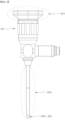
- FIG. 2 is a schematic view showing a camera provided with an endoscope part that is inserted into a hollow hole part of an electrode assembly, to inspect a welding state between a first current collection plate and a first electrode terminal.
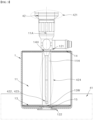
- FIG. 3 is a schematic view showing that a camera provided with an endoscope part is inserted into a hollow hole part of an electrode assembly.
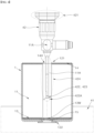
- FIG. 4 is a schematic view showing that a cameral provided with an endoscope part and a wide-angle lens is inserted into a hollow hole part of an electrode assembly, and photographs the inner circumferential surface of the hollow hole part.
- FIG. 5 is a schematic view showing that a camera provided with a telephoto lens photographs a welding portion without being inserted into an electrode assembly.
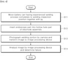
- FIG. 6 is a time-series flowchart showing a method of inspecting a welding state, with a welding inspection apparatus having an endoscope part, on a linear track.
- first means a first component
- second means a second component
- each component can be provided as a single one or a plurality of ones, unless explicitly stated to the contrary.
- any one component can be directly on (or under) another component, but an additional component can be interposed between any one component and another component on (or under) any one component.
- any one component can be directly connected or coupled to another component, but an additional component can be “interposed” between the two components or the two components can be “connected”, “coupled”, or “connected” by an additional component.
- phrase "A and/or B" as used herein can denote A, B or A and B, and the phrase “C to D” can denote C or greater and D or less, unless stated to the contrary.
- a direction (Y) along the lengthwise direction of the winding shaft of an electrode assembly wound in a jelly roll shape is referred to an axial direction or a widthwise direction.
- a direction (X) in which the winding shaft is surrounded is referred to as a circumferential direction or a perimeter direction.
- a direction (Z) closer to the winding shaft or farther from the winding shaft is referred to as a radius direction or a radial direction.
- a direction closer to the winding shaft is referred to as a centripetal direction
- a direction farther from the winding shaft is referred to as a centrifugal direction.
- a welding inspection apparatus and a welding inspection method that are used during manufacturing of a cylindrical battery cell, in particular, a tab-less cylindrical battery cell comprising a jelly roll-type electrode assembly 11 in which anode plate, cathode plate, and separation layers interposed by the electrode plates are stacked and are wound while surrounding the center of the winding.
- the inspection apparatus and the inspection method can be adapted and applied not only to the manufacturing process of the tab-less cylindrical battery cell but also to the inspection of a welding state of a specimen having a long narrow hollow hole part described hereafter and a welding portion at one end of the inner side of the hollow hole part, by one having ordinary skill in the art.
- FIG. 1 is a cross-sectional view showing a cylindrical battery cell during a manufacturing process.
- the cylindrical battery cell comprises a jelly roll-type electrode assembly 11, and a first current collection plate 13 and a second current collection plate 14 welded respectively to a first electrode uncoated part 111 and a second electrode uncoated part 111 that are provided in each end portion of the electrode assembly 11 in an axial direction, which are accommodated in a cylindrical battery can 12 that has a closed surface 122 in the end portion of one side thereof in the axial direction, and an open part 121 in the end portion of the other side thereof in the axial direction, and a first electrode terminal 15 is provided in the central portion of the closed surface 122 and penetrates and is fixed to the closed surface 122.
- the first current collection plate 13 is welded to the first electrode terminal 15 from the inside of the battery can 12, through a hollow hole part 11H that is elongated while passing through a central axis 11A of the electrode assembly 11, and forms a welding portion 13W.
- a weld between the first current collection plate 13 and the first electrode terminal 15 can be performed by inserting a welding rod and a guide, in order not to damage a separation layer and a core (a tube-type member disposed at the center of windings at a jelly roll-type electrode assembly) that can be disposed on the inner surface of the hollow hole part 11H.
- a welding method is not limited to the above-mentioned method. Certainly, various types of welding such as laser welding, resistance welding and the like is applicable.
- the second current collection plate 14 is provide with a central hole 14H having an inner diameter that is the same as or greater than the inner diameter of an open part in the end portion of the other side of the hollow hole part 11H in the axial direction thereof. Accordingly, even after the second current collection plate 14 is welded, the hollow hole part 11H may be open toward the other side of the axial direction thereof. Though described hereafter, since the central hole 14H is provided, a welding state between the first current collection plate 13 and the first electrode terminal 15 can be inspected, even in the state where the second current collection plate 14 is welded.
- the first electrode terminal 15 may be insulated by the battery can 12 and a gasket and the like. Additionally, later, the second current collection plate 14 can connect to the battery can 12 electrically, and at this time, the first electrode terminal 15 may be a terminal that connects the cathode or the anode of the electrode assembly 11 to the outside, and the battery can 12 may be a terminal that connects the anode or the cathode of the electrode assembly 11 to the outside.
- a specimen of the welding inspection apparatus or the welding inspection method according to the present disclosure may be completely assembled or welded in a way that the specimen comprises the battery can 12, the electrode assembly 11, the first current collection plate 13, and the first electrode terminal 15. Further, in the case where the second current collection plate 14 has a central hole 14H, the end portion of the other side of the hollow hole part 11H in the axial direction thereof is open, even in the state where the second current collection plate 14 is completely assembled, making it possible to take an optical approach, i.e., photograph the welding portion 13W. Thus, an welding inspection can proceed in the state where the second current collection plate 14 is completely assembled.
- FIG. 2 is a schematic view showing a camera 42 being included in a welding inspection apparatus of another embodiment and photographing a welding portion 13W, and being provided with an endoscope part 424.
- the camera 42 necessarily comprises a lens 422 and an image sensor 421, and further comprises an endoscope part 424 and/or a lighting device 423.
- the image sensor 421 obtains an image through light coming in from the lens 422, and an image obtained by the image sensor 421 may be transmitted to an image processing device that connects to the outside of the camera 42.
- the image processing device may be a device programmed to analyze the image obtained by the image sensor 421 and determine the welding state of the welding portion 13W.
- the welding state may denote weak welding, normal welding or over welding.
- the image processing device may be a device that can analyze the image of the inner circumferential surface of the hollow hole part 11H, obtained by the image sensor 421, and determine whether weld spatter occurs on the inner circumferential surface of the hollow hole part 11H, in the case where the camera 42 can photographs the inner circumferential surface of the hollow hole part 11H of the electrode assembly 11.
- the endoscope part 424 may be an instrument that can be moved and inserted into the hollow hole part 11H of the electrode assembly 11, and photograph the welding portion 13W.
- the lighting device 423 may be disposed near the lens 422 to radiate light to a photographing portion of the lens 422, and as illustrated in FIG. 2 , may be integrated with the lens 422.
- the lighting device 423 may be disposed in a proper position, in a proper direction, to radiate light into the hollow hole part 11H and light up the welding portion 13W.
- the lighting device 423 may be disposed in the end portion of the endoscope part 424.
- FIG. 3 is a schematic view showing that a camera 42 provided with an endoscope part 424 in one embodiment is inserted into a hollow hole part 11H of an electrode assembly 11.
- a jig 41 fixes the battery can 12 in a way that the open part 121 faces in a first direction, and the camera 42 with the endoscope part 424 is disposed at the open part 121 side of the battery can 12, in the state where the lens 422 disposed in the end portion of the endoscope part 424, and the image sensor 421 disposed at the main body side of the camera 42 are aligned from the welding portion 13W, in the first direction.
- the endoscope part 424 may be elongated along the central axis 11A of the electrode assembly 11, allow the lens 422 to approach to the welding portion 13W, and be inserted into the hollow hole part 11H. As the endoscope part 424 is inserted into the hollow hole part 11H, the camera 42 may photograph the welding portion 13W through the lens 422 provided in the end portion of the endoscope part 424.
- the endoscope part 424 may have an outer diameter that is less than the inner diameter of the hollow hole part 11H.
- the endoscope part 424 may also pass through the central hole 14H provided at the second current collection plate 14 and be inserted into the hollow hole part 11H, and to this end, the endoscope part 424 may have an outer diameter that is less than the inner diameter of the second current collection plate 14.
- the endoscope part 424 may move in various ways to be inserted into the hollow hole part 11H.
- the camera 42 as a whole, may approach and move to the welding portion 13W, for example.
- the endoscope part 424 may only be elongated independently and approach to the welding portion 13W.
- the jig 41 may move the battery can itself along the first direction, such that the endoscope part 424 is inserted into the hollow hole part 11H.
- the lighting device 423 may be provided in the end portion of the endoscope part 424, and may be integrated with the lens 422.
- the endoscope part 424 may be provided with a sub motor to move freely and parallelly on the X-axis, the Y-axis and/or the Z-axis, before and after the endoscope part 424 is inserted into the hollow hole part 11H or while the endoscope part 424 is inserted into the hollow hole part 11H.
- the sub motor may be used to finely adjust a photographing portion or a focal point and the like of the camera 42.
- An image obtained by the image sensor 421 is transmitted to the image processing device through the lens 422, to determine the welding state, i.e., weak welding, normal welding or over welding, of the welding portion13W.
- the image processing device may be programmed to analyze an image that is obtained by the image sensor 421 and transmitted, and to determine the welding state. For example, the image processing device may be programmed to detect whether there is a hole caused by over welding, in the image of the welding portion 13W, which is obtained by the image sensor 421 and transmitted, to determine whether the welding portion 13W is overly welded. That is, the image processing device may be a sort of vision inspection device.
- FIG. 4 is a schematic view showing that a cameral further provided with a wide-angle lens in FIG. 3 is inserted into a hollow hole part of an electrode assembly, and photographs the inner circumferential surface of the hollow hole part.
- the lens provided in the end portion of the endoscope part 424 may be wide-angle lens.
- the wide-angle lens may denote a lens 422 having an angle of view 422A that is wide enough for the camera 42 to photograph the inner circumferential surface of the hollow hole part 11H.
- the image obtained by the image sensor 421 through the lens 422 is transmitted to the image processing device, to determine whether weld spatter occurs on the inner circumferential surface of the hollow hole part 11H.
- the image processing device may be programmed to analyze an image that is obtained by the image sensor 421 and transmitted, and to determine whether weld spatter occurs. For example, the image processing device may be programmed to identify whether a spatter pattern caused by welding is created in the image of the inner circumferential surface of the hollow hole part 11H, which is obtained by the image sensor 421 and transmitted, and to determine whether weld spatter occurs.
- the inspection of the welding state and the inspection of whether weld spatter occurs may be performed by a single welding inspection apparatus comprising the endoscope part 424 that is provided with the wide-angle lens 422 in the end portion of the endoscope part 424, at the same time.
- the image processing device may be programmed to determine the welding state and whether weld spatter occurs, at the same time.
- FIG. 5 is a schematic view showing that a camera provided with a telephoto lens in yet another embodiment photographs a welding portion without being inserted into an electrode assembly.
- the jig 41 fixes the battery can 12 in a way that the open part 121 of the battery can 12 faces in the first direction.
- the camera 42 may be disposed in a way that the lens 422 and the image sensor 421 are aligned in the first direction, with respect to the welding portion 13W. At this time, the camera 42 may not be provided with the endoscope part 424, and the lens 422 may not be inserted into the hollow hole part 11H.
- the lens 422 may be a telephoto lens.
- the telephoto lens may denote a lens that has a narrow angle of view and a long focal length, to photograph the welding portion 13W, without being inserted into the hollow hole part 11H.
- the camera 42 may be provided with a lighting device 423 that is adjacent to the lens 422, and the lighting device 423 may be integrated with the lens 422.
- An image obtained by the image sensor 421 through the lens 422 is transmitted to the image processing device to determine the welding state, i.e., weak welding, normal welding or over welding, of the welding portion 13W.
- the image processing device may be programmed to analyze the image that is obtained by the image sensor 421 and transmitted and to determine the welding state. For example, the image processing device may be programmed to detect whether there is a hole caused by over welding, in an image of the welding portion 13W, which is obtained by the image sensor 421 and transmitted, and to determine whether the welding portion is overly welded.
- a specimen on a linear track may be inspected by the welding inspection apparatus.
- the linear track may be a linear track on which the tab-less cylindrical battery cell is manufactured.
- the specimen experiences a welding process performed by a welding device, before moving to the welding inspection apparatus.
- the welding process may involve a weld between the first current collection plate 13 and the first electrode terminal 15, a weld between the first current collection plate 13 and the first uncoated part 111a, and/or the second current collection plate 14 and the second uncoated part 111b.
- FIG. 6 is a time-series flowchart showing a method of inspecting the welding state of a specimen on a linear track, with a welding inspection apparatus comprising an endoscope part 424 in one embodiment.
- the welding inspection method is described with reference to FIGS. 3 to 6 .
- a battery can 12 having experienced a welding process moves to a position for a welding inspection, on the linear track (S11).
- an open part 121 of the battery can 12 may face in the first direction with the help of the jig 41, and a lens 422 and an image sensor in a camera 42 of the welding inspection apparatus may be aligned and fixed in the first direction along a central axis 11A of an electrode assembly 11, from a welding portion 13W between a first current collection plate 13 and a first electrode terminal 15.
- An endoscope part 424 is inserted into a hollow hole part 11H of the electrode assembly 11 (S12).
- the endoscope part 424 may be elongated to the inside of the hollow hole part 11H from the main body of the camera 42, along the central axis 11A of the electrode assembly 11.
- the endoscope part 424 may be inserted into the hollow hole part 11H, or as the endoscope part 424 only is independently elongated to allow the lens 422 to approach to the welding portion 13W or as the jig 41 moves to allow the battery can 12 to approach to the lens 422, the endoscope part 424 may be inserted into the hollow hole part 11H.
- the lens 422 may be provided in the end portion of the endoscope part 424, and a lighting device 423 may be provided near the lens 422 or integrated with the lens 422.
- the above step (S12) may be omitted in a welding inspection method using a welding inspection apparatus provided with a telephoto lens.
- the camera 42 photographs the welding portion 13W and transmits an image of the welding portion 13W to the image processing device (S13).
- the image of the welding portion 13W is obtained by an image sensor 421 through the lens 422.
- a welding inspection method using a welding inspection apparatus provided with a wide-angle lens may involve photographing the welding portion 13W and the inner circumferential surface of the hollow hole part 11H at the same time, to see whether weld spatter occurs.
- the image processing device analyzes the image and determines failure (S13).
- the image processing device may be programmed to analyze the image, which is obtained by the image sensor 421 and transmitted, and to determine failure. That is, the image processing device may be programmed to analyze the image of the welding portion 13W and to determine weak welding, normal welding or over welding. For example, the image processing device may be programmed to detect whether there is a hole caused by over welding, in the image of the welding portion 13W, and to determine over welding.
- the welding inspection apparatus provided with a wide-angle lens may be programmed to determine the welding state of the welding portion 13W and whether weld spatter occurs on the inner circumferential surface of the hollow hole part 11H, at the same time.
- a trigger input may be set to be provided only when data on a product is present, and may also be set to an inspection pass mode in which an inspection determination signal is ignored may be set in the state where a trigger is always on.
- a defect rate may be set to 200 PPM.
- the tact time of the linear track may be set to 300 ms or less.
- the tact time may also be set to 200 ms or less, considering scan time.
Landscapes
- Engineering & Computer Science (AREA)
- Physics & Mathematics (AREA)
- Chemical & Material Sciences (AREA)
- General Physics & Mathematics (AREA)
- Quality & Reliability (AREA)
- Mechanical Engineering (AREA)
- Analytical Chemistry (AREA)
- Health & Medical Sciences (AREA)
- Pathology (AREA)
- Immunology (AREA)
- General Health & Medical Sciences (AREA)
- Biochemistry (AREA)
- Life Sciences & Earth Sciences (AREA)
- Signal Processing (AREA)
- Multimedia (AREA)
- Chemical Kinetics & Catalysis (AREA)
- Manufacturing & Machinery (AREA)
- Electrochemistry (AREA)
- General Chemical & Material Sciences (AREA)
- Computer Vision & Pattern Recognition (AREA)
- Optics & Photonics (AREA)
- Astronomy & Astrophysics (AREA)
- Theoretical Computer Science (AREA)
- Connection Of Batteries Or Terminals (AREA)
- Investigating Materials By The Use Of Optical Means Adapted For Particular Applications (AREA)
Applications Claiming Priority (3)
| Application Number | Priority Date | Filing Date | Title |
|---|---|---|---|
| KR20210152638 | 2021-11-08 | ||
| KR1020220055065A KR20230067468A (ko) | 2021-11-08 | 2022-05-03 | 용접 검사 장치 |
| PCT/KR2022/017417 WO2023080756A1 (ko) | 2021-11-08 | 2022-11-08 | 용접 검사 장치 |
Publications (3)
| Publication Number | Publication Date |
|---|---|
| EP4431920A1 true EP4431920A1 (de) | 2024-09-18 |
| EP4431920A4 EP4431920A4 (de) | 2025-01-29 |
| EP4431920B1 EP4431920B1 (de) | 2025-12-31 |
Family
ID=86241519
Family Applications (1)
| Application Number | Title | Priority Date | Filing Date |
|---|---|---|---|
| EP22890487.6A Active EP4431920B1 (de) | 2021-11-08 | 2022-11-08 | Schweissprüfvorrichtung und schweissprüfverfahren |
Country Status (5)
| Country | Link |
|---|---|
| US (1) | US20250024130A1 (de) |
| EP (1) | EP4431920B1 (de) |
| JP (1) | JP7764601B2 (de) |
| CA (1) | CA3237559A1 (de) |
| WO (1) | WO2023080756A1 (de) |
Families Citing this family (1)
| Publication number | Priority date | Publication date | Assignee | Title |
|---|---|---|---|---|
| JP2025526048A (ja) * | 2022-12-12 | 2025-08-07 | エルジー エナジー ソリューション リミテッド | バッテリー検査装置 |
Family Cites Families (22)
| Publication number | Priority date | Publication date | Assignee | Title |
|---|---|---|---|---|
| JPS62283309A (ja) * | 1986-05-21 | 1987-12-09 | Olympus Optical Co Ltd | 内視鏡の先端部 |
| KR0165606B1 (ko) * | 1995-11-30 | 1999-01-15 | 배순훈 | 밧데리 조립 불량상태 검출장치 및 그 제어방법 |
| JP2001043834A (ja) * | 1999-08-02 | 2001-02-16 | Toshiba Battery Co Ltd | 電池外装ケースの検査装置 |
| US20070203396A1 (en) * | 2006-02-28 | 2007-08-30 | Mccutcheon John G | Endoscopic Tool |
| KR100938896B1 (ko) * | 2007-10-26 | 2010-01-27 | 삼성에스디아이 주식회사 | 배터리 팩 |
| KR101012654B1 (ko) * | 2009-01-19 | 2011-02-09 | (주)시그널웍스 | 원통형 건전지 캔의 자동 검사장치 및 방법 |
| GB0903232D0 (en) * | 2009-02-25 | 2009-04-08 | Saipem Spa | A method for testing pipeline welds |
| JP2011133288A (ja) * | 2009-12-24 | 2011-07-07 | Panasonic Corp | 筒状物品の画像検査用照明方法およびその照明装置 |
| KR101287464B1 (ko) * | 2012-05-21 | 2013-07-23 | 이시자키코리아 주식회사 | 이차 건전지용 캔의 자동검사장치 |
| KR102060372B1 (ko) * | 2012-09-19 | 2019-12-30 | 한국전자통신연구원 | 내시경 가이드 장치 및 방법 |
| KR101894961B1 (ko) * | 2016-09-29 | 2018-09-05 | 주식회사 제이이노텍 | 원통형 전지의 용접 상태 검사장치 |
| CN106825958B (zh) * | 2017-03-16 | 2018-09-28 | 深圳市光大激光科技股份有限公司 | 电芯自动焊接检测装置和方法 |
| KR101975562B1 (ko) * | 2017-07-31 | 2019-05-07 | (주)자비스 | 내부 결함 및 접합 부위의 검사가 가능한 엑스레이 검사 장치 |
| CN209559779U (zh) | 2019-01-17 | 2019-10-29 | 深圳杰泰科技有限公司 | 内窥探伤检测仪 |
| JP7121911B2 (ja) * | 2019-01-29 | 2022-08-19 | トヨタ自動車株式会社 | 溶接品質検査方法および溶接品質検査装置 |
| CN109613012A (zh) | 2019-02-20 | 2019-04-12 | 南京工业大学 | 一种基于内窥镜的产品缺陷检测系统及检测方法 |
| CN109738454B (zh) * | 2019-03-18 | 2024-07-05 | 福建工程学院 | 一种软包电池极耳焊缝检测装置及方法 |
| KR102622753B1 (ko) * | 2020-02-17 | 2024-01-10 | 삼성에스디아이 주식회사 | 이차전지용 레이저 용접 방법 및 모니터링 방법 |
| KR102341944B1 (ko) | 2020-06-08 | 2021-12-22 | 이성관 | 식기 세척 시스템 |
| KR20220055065A (ko) | 2020-10-26 | 2022-05-03 | 주식회사 뉴아인 | 비정상 분열 세포에 대한 사멸 유도 장치 및 이의 구동 방법 |
| KR102294189B1 (ko) | 2021-04-16 | 2021-08-27 | 주식회사 성안테크 | 원통형 배터리의 전극 용접 검사장치 |
| KR20230008444A (ko) * | 2021-07-07 | 2023-01-16 | 현대자동차주식회사 | 배터리 모듈 용접부 미융착 검출 시스템 및 방법 |
-
2022
- 2022-11-08 US US18/708,023 patent/US20250024130A1/en active Pending
- 2022-11-08 JP JP2024527221A patent/JP7764601B2/ja active Active
- 2022-11-08 WO PCT/KR2022/017417 patent/WO2023080756A1/ko not_active Ceased
- 2022-11-08 EP EP22890487.6A patent/EP4431920B1/de active Active
- 2022-11-08 CA CA3237559A patent/CA3237559A1/en active Pending
Also Published As
| Publication number | Publication date |
|---|---|
| WO2023080756A1 (ko) | 2023-05-11 |
| CA3237559A1 (en) | 2023-05-11 |
| JP7764601B2 (ja) | 2025-11-05 |
| EP4431920B1 (de) | 2025-12-31 |
| EP4431920A4 (de) | 2025-01-29 |
| JP2024540418A (ja) | 2024-10-31 |
| US20250024130A1 (en) | 2025-01-16 |
Similar Documents
| Publication | Publication Date | Title |
|---|---|---|
| US20220390387A1 (en) | Device and method for inspecting air void at lead film of battery | |
| KR20200105272A (ko) | 전극 조립체 제조방법 및 전극 조립체 제조장치 | |
| KR102840741B1 (ko) | 이차 전지 및 이차 전지의 제조 방법 | |
| KR102721576B1 (ko) | 전지 및 그 제조 방법 | |
| EP4431920A1 (de) | Schweissprüfvorrichtung | |
| CN115428227B (zh) | 检测电极接片的缺陷的系统和使用该系统来检测电极接片的缺陷的方法 | |
| US20240302425A1 (en) | Secondary Battery Cell Insulation Test Apparatus and Method Using the Same | |
| KR102425230B1 (ko) | 이차전지용 용접상태 검사 방법 | |
| US11841328B2 (en) | Method and device for testing electrode sheet | |
| EP4447190A1 (de) | Verfahren zur inspektion eines batteriemoduls | |
| KR20230067468A (ko) | 용접 검사 장치 | |
| EP4571243A1 (de) | Vorrichtung zur inspektion einer elektrodenanordnung und batteriezelle mit einer damit hergestellten elektrodenanordnung sowie batteriepack und fahrzeug mit batteriezellen | |
| CN118215838A (zh) | 焊接检查设备 | |
| EP4249904B1 (de) | Vorrichtung und verfahren zur erkennung interner defekte einer batteriezelle unter verwendung von tdr | |
| US20250309384A1 (en) | Battery inspection apparatus and inspection method of the same | |
| JP7610547B2 (ja) | 電池の製造方法 | |
| EP4700328A1 (de) | Defektinspektionsvorrichtung und defektinspektionsverfahren | |
| US20260102784A1 (en) | Apparatus and method for cleaning coating liquid nozzle | |
| CN120677578A (zh) | 圆柱形电池单元检查装置和使用该圆柱形电池单元检查装置制造的圆柱形电池单元、以及包括圆柱形电池单元的电池组和车辆 | |
| KR20250101764A (ko) | 원통형 배터리 셀 검사 장치 및 이를 사용하여 생산된 원통형 배터리 셀 및, 원통형 배터리 셀을 포함하는 배터리 팩 및 자동차 | |
| KR20250113622A (ko) | 이미지센서를 이용한 이물질 정밀진단 제거장치 | |
| WO2024248289A1 (ko) | 원통형 배터리 셀의 용접에 사용되는 지그 및 이를 사용하는 원통형 배터리 셀 제조 방법 및 이에 따라 생산된 원통형 배터리 셀 및 원통형 배터리 셀을 포함하는 배터리 팩 및 자동차 | |
| WO2025173874A1 (ko) | 배터리 셀 및 이를 포함하는 배터리 팩 및 자동차 | |
| KR20250125854A (ko) | 배터리 셀 및 이를 포함하는 배터리 팩 및 자동차 | |
| KR20250085907A (ko) | 원통형 배터리 셀 검사 장치 및 이를 사용하여 생산된 원통형 배터리 셀 및, 원통형 배터리 셀을 포함하는 배터리 팩 및 자동차 |
Legal Events
| Date | Code | Title | Description |
|---|---|---|---|
| STAA | Information on the status of an ep patent application or granted ep patent |
Free format text: STATUS: THE INTERNATIONAL PUBLICATION HAS BEEN MADE |
|
| PUAI | Public reference made under article 153(3) epc to a published international application that has entered the european phase |
Free format text: ORIGINAL CODE: 0009012 |
|
| STAA | Information on the status of an ep patent application or granted ep patent |
Free format text: STATUS: REQUEST FOR EXAMINATION WAS MADE |
|
| 17P | Request for examination filed |
Effective date: 20240506 |
|
| AK | Designated contracting states |
Kind code of ref document: A1 Designated state(s): AL AT BE BG CH CY CZ DE DK EE ES FI FR GB GR HR HU IE IS IT LI LT LU LV MC ME MK MT NL NO PL PT RO RS SE SI SK SM TR |
|
| A4 | Supplementary search report drawn up and despatched |
Effective date: 20250108 |
|
| RIC1 | Information provided on ipc code assigned before grant |
Ipc: B23K 31/12 20060101ALI20241223BHEP Ipc: G01N 21/954 20060101ALI20241223BHEP Ipc: G01N 21/952 20060101ALI20241223BHEP Ipc: G01N 21/88 20060101AFI20241223BHEP |
|
| DAV | Request for validation of the european patent (deleted) | ||
| DAX | Request for extension of the european patent (deleted) | ||
| STAA | Information on the status of an ep patent application or granted ep patent |
Free format text: STATUS: EXAMINATION IS IN PROGRESS |
|
| 17Q | First examination report despatched |
Effective date: 20250520 |
|
| GRAP | Despatch of communication of intention to grant a patent |
Free format text: ORIGINAL CODE: EPIDOSNIGR1 |
|
| STAA | Information on the status of an ep patent application or granted ep patent |
Free format text: STATUS: GRANT OF PATENT IS INTENDED |
|
| INTG | Intention to grant announced |
Effective date: 20250811 |
|
| GRAS | Grant fee paid |
Free format text: ORIGINAL CODE: EPIDOSNIGR3 |
|
| GRAA | (expected) grant |
Free format text: ORIGINAL CODE: 0009210 |
|
| STAA | Information on the status of an ep patent application or granted ep patent |
Free format text: STATUS: THE PATENT HAS BEEN GRANTED |
|
| P01 | Opt-out of the competence of the unified patent court (upc) registered |
Free format text: CASE NUMBER: UPC_APP_0011430_4431920/2025 Effective date: 20251029 |
|
| AK | Designated contracting states |
Kind code of ref document: B1 Designated state(s): AL AT BE BG CH CY CZ DE DK EE ES FI FR GB GR HR HU IE IS IT LI LT LU LV MC ME MK MT NL NO PL PT RO RS SE SI SK SM TR |
|
| REG | Reference to a national code |
Ref country code: CH Ref legal event code: F10 Free format text: ST27 STATUS EVENT CODE: U-0-0-F10-F00 (AS PROVIDED BY THE NATIONAL OFFICE) Effective date: 20251231 Ref country code: GB Ref legal event code: FG4D |
|
| REG | Reference to a national code |
Ref country code: DE Ref legal event code: R096 Ref document number: 602022028163 Country of ref document: DE |
|
| REG | Reference to a national code |
Ref country code: IE Ref legal event code: FG4D |
|
| REG | Reference to a national code |
Ref country code: LT Ref legal event code: MG9D |
|
| PG25 | Lapsed in a contracting state [announced via postgrant information from national office to epo] |
Ref country code: NO Free format text: LAPSE BECAUSE OF FAILURE TO SUBMIT A TRANSLATION OF THE DESCRIPTION OR TO PAY THE FEE WITHIN THE PRESCRIBED TIME-LIMIT Effective date: 20260331 |
|
| PG25 | Lapsed in a contracting state [announced via postgrant information from national office to epo] |
Ref country code: HR Free format text: LAPSE BECAUSE OF FAILURE TO SUBMIT A TRANSLATION OF THE DESCRIPTION OR TO PAY THE FEE WITHIN THE PRESCRIBED TIME-LIMIT Effective date: 20251231 Ref country code: FI Free format text: LAPSE BECAUSE OF FAILURE TO SUBMIT A TRANSLATION OF THE DESCRIPTION OR TO PAY THE FEE WITHIN THE PRESCRIBED TIME-LIMIT Effective date: 20251231 |
|
| PG25 | Lapsed in a contracting state [announced via postgrant information from national office to epo] |
Ref country code: RS Free format text: LAPSE BECAUSE OF FAILURE TO SUBMIT A TRANSLATION OF THE DESCRIPTION OR TO PAY THE FEE WITHIN THE PRESCRIBED TIME-LIMIT Effective date: 20260331 |