EP4431912A1 - Biological sample measuring device - Google Patents
Biological sample measuring device Download PDFInfo
- Publication number
- EP4431912A1 EP4431912A1 EP22889679.1A EP22889679A EP4431912A1 EP 4431912 A1 EP4431912 A1 EP 4431912A1 EP 22889679 A EP22889679 A EP 22889679A EP 4431912 A1 EP4431912 A1 EP 4431912A1
- Authority
- EP
- European Patent Office
- Prior art keywords
- biological sample
- light
- imager
- measuring device
- mirror
- Prior art date
- Legal status (The legal status is an assumption and is not a legal conclusion. Google has not performed a legal analysis and makes no representation as to the accuracy of the status listed.)
- Pending
Links
Images







Classifications
-
- G—PHYSICS
- G01—MEASURING; TESTING
- G01N—INVESTIGATING OR ANALYSING MATERIALS BY DETERMINING THEIR CHEMICAL OR PHYSICAL PROPERTIES
- G01N21/00—Investigating or analysing materials by the use of optical means, i.e. using sub-millimetre waves, infrared, visible or ultraviolet light
- G01N21/17—Systems in which incident light is modified in accordance with the properties of the material investigated
- G01N21/25—Colour; Spectral properties, i.e. comparison of effect of material on the light at two or more different wavelengths or wavelength bands
- G01N21/27—Colour; Spectral properties, i.e. comparison of effect of material on the light at two or more different wavelengths or wavelength bands using photo-electric detection ; circuits for computing concentration
-
- G—PHYSICS
- G01—MEASURING; TESTING
- G01N—INVESTIGATING OR ANALYSING MATERIALS BY DETERMINING THEIR CHEMICAL OR PHYSICAL PROPERTIES
- G01N21/00—Investigating or analysing materials by the use of optical means, i.e. using sub-millimetre waves, infrared, visible or ultraviolet light
- G01N21/17—Systems in which incident light is modified in accordance with the properties of the material investigated
- G01N21/25—Colour; Spectral properties, i.e. comparison of effect of material on the light at two or more different wavelengths or wavelength bands
- G01N21/31—Investigating relative effect of material at wavelengths characteristic of specific elements or molecules, e.g. atomic absorption spectrometry
- G01N21/35—Investigating relative effect of material at wavelengths characteristic of specific elements or molecules, e.g. atomic absorption spectrometry using infrared light
- G01N21/359—Investigating relative effect of material at wavelengths characteristic of specific elements or molecules, e.g. atomic absorption spectrometry using infrared light using near infrared light
-
- G—PHYSICS
- G01—MEASURING; TESTING
- G01N—INVESTIGATING OR ANALYSING MATERIALS BY DETERMINING THEIR CHEMICAL OR PHYSICAL PROPERTIES
- G01N21/00—Investigating or analysing materials by the use of optical means, i.e. using sub-millimetre waves, infrared, visible or ultraviolet light
- G01N21/17—Systems in which incident light is modified in accordance with the properties of the material investigated
- G01N21/25—Colour; Spectral properties, i.e. comparison of effect of material on the light at two or more different wavelengths or wavelength bands
- G01N21/31—Investigating relative effect of material at wavelengths characteristic of specific elements or molecules, e.g. atomic absorption spectrometry
- G01N21/314—Investigating relative effect of material at wavelengths characteristic of specific elements or molecules, e.g. atomic absorption spectrometry with comparison of measurements at specific and non-specific wavelengths
-
- G—PHYSICS
- G01—MEASURING; TESTING
- G01N—INVESTIGATING OR ANALYSING MATERIALS BY DETERMINING THEIR CHEMICAL OR PHYSICAL PROPERTIES
- G01N21/00—Investigating or analysing materials by the use of optical means, i.e. using sub-millimetre waves, infrared, visible or ultraviolet light
- G01N21/17—Systems in which incident light is modified in accordance with the properties of the material investigated
- G01N21/25—Colour; Spectral properties, i.e. comparison of effect of material on the light at two or more different wavelengths or wavelength bands
- G01N21/31—Investigating relative effect of material at wavelengths characteristic of specific elements or molecules, e.g. atomic absorption spectrometry
- G01N21/35—Investigating relative effect of material at wavelengths characteristic of specific elements or molecules, e.g. atomic absorption spectrometry using infrared light
- G01N21/3577—Investigating relative effect of material at wavelengths characteristic of specific elements or molecules, e.g. atomic absorption spectrometry using infrared light for analysing liquids, e.g. polluted water
-
- G—PHYSICS
- G01—MEASURING; TESTING
- G01N—INVESTIGATING OR ANALYSING MATERIALS BY DETERMINING THEIR CHEMICAL OR PHYSICAL PROPERTIES
- G01N33/00—Investigating or analysing materials by specific methods not covered by groups G01N1/00 - G01N31/00
- G01N33/48—Biological material, e.g. blood, urine; Haemocytometers
-
- G—PHYSICS
- G01—MEASURING; TESTING
- G01N—INVESTIGATING OR ANALYSING MATERIALS BY DETERMINING THEIR CHEMICAL OR PHYSICAL PROPERTIES
- G01N35/00—Automatic analysis not limited to methods or materials provided for in any single one of groups G01N1/00 - G01N33/00; Handling materials therefor
- G01N35/10—Devices for transferring samples or any liquids to, in, or from, the analysis apparatus, e.g. suction devices, injection devices
- G01N35/1009—Characterised by arrangements for controlling the aspiration or dispense of liquids
-
- G—PHYSICS
- G01—MEASURING; TESTING
- G01N—INVESTIGATING OR ANALYSING MATERIALS BY DETERMINING THEIR CHEMICAL OR PHYSICAL PROPERTIES
- G01N35/00—Automatic analysis not limited to methods or materials provided for in any single one of groups G01N1/00 - G01N33/00; Handling materials therefor
- G01N35/00584—Control arrangements for automatic analysers
- G01N35/00722—Communications; Identification
- G01N35/00732—Identification of carriers, materials or components in automatic analysers
- G01N2035/00742—Type of codes
- G01N2035/00752—Type of codes bar codes
-
- G—PHYSICS
- G01—MEASURING; TESTING
- G01N—INVESTIGATING OR ANALYSING MATERIALS BY DETERMINING THEIR CHEMICAL OR PHYSICAL PROPERTIES
- G01N2201/00—Features of devices classified in G01N21/00
- G01N2201/06—Illumination; Optics
- G01N2201/061—Sources
- G01N2201/06126—Large diffuse sources
-
- G—PHYSICS
- G01—MEASURING; TESTING
- G01N—INVESTIGATING OR ANALYSING MATERIALS BY DETERMINING THEIR CHEMICAL OR PHYSICAL PROPERTIES
- G01N2201/00—Features of devices classified in G01N21/00
- G01N2201/06—Illumination; Optics
- G01N2201/064—Stray light conditioning
-
- G—PHYSICS
- G01—MEASURING; TESTING
- G01N—INVESTIGATING OR ANALYSING MATERIALS BY DETERMINING THEIR CHEMICAL OR PHYSICAL PROPERTIES
- G01N2201/00—Features of devices classified in G01N21/00
- G01N2201/06—Illumination; Optics
- G01N2201/064—Stray light conditioning
- G01N2201/0642—Light traps; baffles
-
- H—ELECTRICITY
- H04—ELECTRIC COMMUNICATION TECHNIQUE
- H04N—PICTORIAL COMMUNICATION, e.g. TELEVISION
- H04N23/00—Cameras or camera modules comprising electronic image sensors; Control thereof
- H04N23/60—Control of cameras or camera modules
Definitions
- the present disclosure relates to a device that measures a biological sample separated into a plurality of component regions.
- a technique for automating a related-art liquid amount checking operation of a biological specimen before opening (before dispensing) performed by visual checking For the purpose of improving efficiency of clinical tests such as blood tests, there is a demand for a technique for automating a related-art liquid amount checking operation of a biological specimen before opening (before dispensing) performed by visual checking.
- a biological sample such as a blood specimen before dispensing is separated into a plurality of layers by centrifugal separation or the like, and a technique for measuring only a liquid amount of a sample that is an analysis target is required.
- a barcode label for identification or a pre-label attached to a blood collection tube and shipped may be attached to the biological sample before dispensing, there is a demand for a technique capable of performing measurement in a state where the labels are attached.
- Patent Literature 1 discloses a technique in which pulsed light having two wavelengths is radiated by performing switching in a time-division manner to a sample separated into a plurality of layers, and transmitted light is measured while scanning the sample in a vertical direction, thereby detecting a height of a predetermined region of the sample separated into the plurality of layers.
- Patent Literature 2 discloses a liquid detection device in which infrared light is applied to a specimen to detect transmitted light by a line sensor, a boundary of a label is obtained based on a first-order differential value thereof, and a serum amount of the specimen is measured. Further, in Patent Literature 2, a signal of the transmitted light is acquired by changing a light amount, so that analysis can be performed regardless of presence or absence of attenuation of the transmitted light due to the label.
- Patent Literature 1 relates to a liquid amount measurement technique in which, for the biological sample including the plurality of components, a boundary of a measurement target region is accurately specified to measure a liquid amount based on signals of the transmitted light having two wavelengths with different absorptances for a measurement target.
- Patent Literature 1 it is necessary to perform measurement while vertically scanning a specimen (blood collection tube) in a longitudinal direction, and there is a problem that it is difficult to miniaturize the device due to a scanning mechanism.
- Patent Literature 2 an upper surface and a lower surface of serum are detected to measure a serum amount by signal processing based on differentiation from a signal of transmitted infrared light.
- infrared rays are absorbed or scattered by characters printed on a blood collection tube, a blood cell component in a separating agent, color characters on a label, and the like, and the transmitted light is attenuated, there is a problem that it is difficult to separate the noises from a boundary of the serum, and accuracy of specifying the boundary of the serum and measuring a liquid amount may decrease.
- the present disclosure has been made in view of the problem described above, and an object thereof is to provide a technique in which, when measuring a biological sample stored in a container to which a label is attached and separated into a plurality of component regions, a target portion that is a measurement target can be accurately specified without using a large-sized imaging mechanism.
- a mirror is disposed on an optical path from a surface light source to an area camera, so that light transmitted through a biological sample is guided into the area camera while being refracted, and a light-absorbing material is disposed at a position where reflected light reflected and returned toward the biological sample is blocked.
- a biological sample measuring device of the present disclosure it is possible to accurately specify a target portion that is a measurement target without using a large-sized imaging mechanism when measuring a biological sample stored in a container to which a label is attached and separated into a plurality of component regions.
- FIG. 1 is a plan view showing a configuration of a biological sample measuring device 100 according to Embodiment 1 of the present disclosure.
- the biological sample measuring device 100 is a device that measures a biological sample 101.
- the biological sample 101 is a sample configured as described above.
- the biological sample measuring device 100 specifies a measurement target region of the biological sample 101, and measures a liquid amount thereof.
- the biological sample measuring device 100 includes a surface illumination light source 102, an area camera 103, a first mirror 104, a second mirror 105, an absorber 106, and an image processing unit 108.
- the surface illumination light source 102 switches a wavelength of emitted light between two wavelengths, and illuminates the biological sample 101 with the light.
- the light emitted from the surface illumination light source 102 can simultaneously illuminate two or more component layers (that is, across two or more component layers) that constitute the biological sample 101. Further, regardless of the component layer, an upper surface of an uppermost layer (a boundary between the sample and an air layer) can be radiated.
- the area camera 103 images surface illumination light transmitted through the biological sample 101, thereby generating a two-dimensional captured image of the biological sample 101.
- the area camera 103 has sensitivity characteristics that can detect light in a wavelength band emitted from the surface illumination light source 102.
- the area camera 103 can be implemented by, for example, an InGaAs camera.
- the first mirror 104 reflects the transmitted light transmitted through the biological sample 101 toward the second mirror 105.
- the second mirror 105 reflects the transmitted light reflected on the first mirror 104 toward the area camera 103. Accordingly, the transmitted light is reflected twice from transmitted through the biological sample 101 until reaching the area camera 103, and the optical path is refracted twice due to the reflection.
- the absorber 106 has characteristics of attenuating a light amount of the transmitted light transmitted through the biological sample 101 by at least partially absorbing the transmitted light transmitted through the biological sample 101. A size and an arrangement of the absorber 106 will be described later.
- the image processing unit 108 extracts the measurement target region (an image region of the specimen) from the captured image acquired by the area camera 103. An extraction principle will be described below.
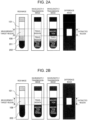
- FIGS. 2A and 2B are diagrams illustrating a principle for specifying the measurement target region.
- the area camera 103 captures a two-dimensional transmission image of the biological sample 101 as shown in FIGS. 2A and 2B .
- FIG. 2A shows an example in which the biological sample 101 is separated into three layers.
- FIG. 2B shows an example in which the biological sample 101 is separated into two layers.
- a blood clot 202 is formed at a lower layer when the biological sample 101 is centrifugally separated.
- a separating agent 201 is mixed to separate the blood clot 202 from the measurement target region 109.
- a transmittance when the wavelength 1 is transmitted through the blood clot 202 and a transmittance when the wavelength 2 is transmitted through the blood clot 202 are substantially the same. Therefore, a difference between a captured image of the blood clot 202 acquired using the wavelength 1 and a captured image of the blood clot 202 acquired using the wavelength 2 is very small. Similarly, for the separating agent 201, since the transmittance of the wavelength 1 and the transmittance of the wavelength 2 are substantially the same, a difference between the two images is very small.
- a transmittance when the wavelength 1 is transmitted through the measurement target region 109 and a transmittance when the wavelength 2 is transmitted through the measurement target region 109 are greatly different. Therefore, a difference between a captured image of the measurement target region 109 acquired using the wavelength 1 and a captured image of the measurement target region 109 acquired using the wavelength 2 is remarkable. The difference is identified, whereby the measurement target region 109 can be extracted from the captured images.
- Wavelength bands adopted as the wavelength 1 and the wavelength 2 need to be selected in advance such that a remarkable difference is generated between the wavelengths in the measurement target region 109, but almost no difference is generated in other portions as exemplified in FIGS. 2A and 2B .
- a specific numerical value of a wavelength may be optional. That is, at least a difference between the transmittance when the wavelength 1 is transmitted through the measurement target region 109 and the transmittance when the wavelength 2 is transmitted through the measurement target region 109 just needs to be larger than a difference between a transmittance when the wavelength 1 is transmitted through a region other than the measurement target region 109 and a transmittance when the wavelength 2 is transmitted through a region other than the measurement target region 109.
- the measurement target region 109 can be specified.
- the image processing unit 108 specifies the measurement target region 109 according to the principle. Although the number of component layers does not matter, a typical biological sample such as plasma or serum is separated into one to three layers. In either case, the measurement target region 109 can be accurately specified.
- the biological sample 101 having one component layer and the biological sample 101 having three component layers when the number of component layers is known in advance before the measurement, measurement can be performed using a transmission image having only one wavelength.
- a wavelength having a difference in an absorptance between the air layer and the separating agent 201 located above and below the measurement target region 109 and the measurement target region 109 may be selected.
- a wavelength having a difference between the air layer above the measurement target region 109 and an absorptance of the measurement target region 109 may be selected.
- FIG. 3A shows a configuration of the image processing unit 108.
- the image processing unit 108 analyzes a captured image having each wavelength acquired by the area camera 103.
- the image processing unit 108 includes an image acquisition unit 1081, a measurement target region specifying unit 1082, and a liquid amount calculation unit 1083.
- the image acquisition unit 1081 acquires transmission images having two wavelengths captured by the area camera 103.
- the measurement target region specifying unit 1082 specifies the measurement target region 109 by comparing the captured images having the wavelengths.
- the liquid amount calculation unit 1083 calculates a liquid amount in the measurement target region 109.
- FIG. 3B is a flowchart illustrating an example of processing of specifying the measurement target region 109 from the transmission images and calculating a liquid amount thereof by the image processing unit 108.
- steps in FIG. 3B will be described.
- the measurement target region specifying unit 1082 acquires the captured images at the wavelength 1 and the wavelength 2.
- exposure time may use, for example, a value predetermined as a specified value.
- the measurement target region specifying unit 1082 calculates a difference image between the captured image at the wavelength 1 and the captured image at the wavelength 2.
- the difference image illustrated in FIGS. 2A and 2B is calculated, and the difference image can be acquired by calculating a difference in pixel values of the images. Examples of a calculation procedure include the following: (a) wavelength 1 image - wavelength 2 image; (b) wavelength 2 image - wavelength 1 image; and (c) (wavelength 1 image - wavelength 2 image)/(wavelength 1 image + wavelength 2 image).
- the present step is omitted, and a boundary of each layer is specified using processing such as edge detection in S305.
- the measurement target region specifying unit 1082 sets a threshold for detecting the measurement target region 109.
- the measurement target region specifying unit 1082 extracts, as the measurement target region 109, a portion of the difference image whose pixel value is equal to or larger than the threshold.
- the measurement target region specifying unit 1082 detects an edge (height) of the measurement target region 109.
- an edge detection method for example, the following can be used: (a) an edge detection algorithm based on a luminance gradient (inclination), a differential value, or the like in a vertical direction; (b) pixel values of the extracted measurement target region 109 are integrated in a horizontal direction to be one-dimensional, and an edge in a perpendicular direction is specified using a signal inclination, a differential value, a variance value, or the like in the perpendicular direction.
- a specification result can be stored as coordinate values on a captured image. That is, statistics of the pixel values in the horizontal direction are calculated as feature values in the horizontal direction, and the feature values are compared along the vertical direction, whereby upper and lower edges of the measurement target region 109 can be specified.
- the liquid amount calculation unit 1083 can calculate a liquid amount in the measurement target region 109 by using a result in the present step. For example, after boundaries of the layers are specified, a liquid amount in a corresponding region is calculated using information on a pixel pitch, the number of extracted pixels, and an inner diameter of a container of the biological sample 101.
- FIG. 4 is a diagram illustrating a working distance of the area camera 103.
- a working distance a distance from the biological sample 101 to a lens of the area camera 103.
- the necessary working distance is obtained using a focal length of the lens, a necessary field of view, and a sensor size.
- the necessary field of view is 100 mm that is a length of a blood collection tube (specimen container)
- the focal length is 8 mm
- the sensor size is 6.4 mm (long side)
- the working distance is 125 m. That is, in order to image the entire biological sample, it is necessary to dispose the biological sample 101 and the area camera 103 by a distance of 125 mm.
- the optical path of the transmitted light is folded back by using the two mirrors.
- the configuration in which the optical path is refracted is adopted as described above, whereby a sufficient working distance can be secured while reducing an area size of the biological sample measuring device 100. Further, a size of the biological sample measuring device 100 can be changed according to an application by an arrangement of the mirrors.
- the surface illumination light source 102 has a size of a region sandwiched by lines that connect an outermost shape of the biological sample 101 to a center of the area camera 103. Therefore, it is desirable that a size of the surface illumination light source 102 in an upper-lower direction in the drawing in FIG. 4 secures the size of the region sandwiched by the lines that connect the outermost shape shown in FIG. 4 .
- a height the size in the upper-lower direction in the drawing in FIG. 4
- a height of the surface illumination light source 102 is 120 mm based on a similarity relationship of a triangle.
- FIGS. 5A and 5B show an example in which a label 107 is attached to a container of the biological sample 101.
- FIG. 5A is a side view of the container
- FIG. 5B is a top view thereof.
- a barcode label, a pre-label, or the like may be attached to the container (for example, a blood collection tube) of the biological sample 101. Even in such a case, it is required to accurately specify the measurement target region 109.
- FIGS. 6A and 6B are diagrams illustrating a problem related to re-illumination. Under the condition of the label as shown in FIG. 5 , a problem related to re-illumination of the transmitted light occurs.
- miniaturization is implemented by using the two mirrors as shown in FIG. 1 , light scattered and transmitted from the biological sample 101 is reflected on the second mirror 105, and re-illumination light that illuminates a sample surface on a side opposite to the surface illumination light source 102 is generated via an optical path as indicated by solid lines in FIG. 6A .
- a similar problem related to the re-illumination also occurs, when the surface illumination light source 102 directly radiates the area camera 103 (an arrow directed from the surface illumination light source 102 toward the area camera 103 in FIG. 6A ) and light reflected on the area camera 103 illuminates the biological sample 101 (an arrow directed from the area camera 103 toward the biological sample 101 in FIG. 6A ).
- the size and the arrangement of the absorber 106 are implemented as follows in present Embodiment 1.
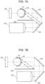
- FIG. 7A is a diagram showing re-illumination light from the second mirror 105.
- a dotted line indicates an optical path of effective light flux necessary for acquiring an image of the biological sample 101 by the area camera 103.
- a one-dot chain line indicates a line where a normal line of the second mirror 105 overlaps the biological sample 101. When a path of the one-dot chain line is valid (that is, the transmitted light can reach the biological sample 101 via the path), light scattered on the label 107 is reflected on the second mirror 105, and re-illumination light that re-illuminates the label 107 is generated.
- FIG. 7B is a diagram illustrating a method for preventing the re-illumination light from the second mirror 105.
- the working distance is determined based on the field of view necessary for analysis, the sensor size of the area camera 103, and the focal length of the lens, it is not possible to prevent the re-illumination light by changing a distance between the area camera 103 and the biological sample 101. Therefore, while maintaining the working distance, the first mirror 104 and the second mirror 105 are separated from the biological sample 101, and an interval between the area camera 103 and the second mirror 105 is shortened. Accordingly, an arrangement relationship as shown in FIG. 7B is established while maintaining the working distance.
- the absorber 106 blocks the re-illumination light by disposing the absorber 106 on the optical path indicated by the one-dot chain line. That is, the size and the arrangement position of the absorber 106 block the transmitted light reflected on the second mirror 105 from re-illuminating the biological sample 101 (more specifically, the label 107). Accordingly, it is possible to solve the problem of the re-illumination described in FIG. 6A .
- the absorber 106 does not block the transmitted light reflected from the first mirror 104 toward the second mirror 105.
- the absorber 106 is disposed such that a right end of the absorber 106 does not overlap a straight line that connects a left end of the first mirror 104 to a left end of the second mirror 105. Accordingly, the absorber 106 can block only the path of the re-illumination light indicated by the one-dot chain line without obstructing the path of the effective light flux indicated by the dotted line.
- the arrangement in FIG. 7B also has the following advantages.
- a related-art arrangement relationship between the surface illumination light source 102 and the area camera 103 as shown in FIG. 4 since wiring that supplies power to the surface illumination light source 102 extends to a left side of the drawing, and wiring that supplies the power to the area camera 103 extends to a right side of the drawing, a size of a space for housing the wiring is increased.
- a size of a space for housing the wiring is increased.
- the surface illumination light source 102 and the area camera 103 are disposed such that a direction in which the surface illumination light source 102 emits light and a direction of light when the area camera 103 receives light are parallel to each other, and face the same orientation.
- FIG. 8 shows a modification of the absorber 106.
- the shape of the absorber 106 does not necessarily have to be planar.
- the absorber 106 may have a bent shape obtained by being refracted at one or more locations as shown in FIG. 8 (that is, two or more portions that block the optical path indicated by the one-dot chain line may be provided).
- the absorber 106 is bent, it is easier to create an interval between the path of the effective light flux indicated by the dotted line and the absorber 106. This is because even if the interval is created, it is sufficient that at least one of the bent portions blocks the one-dot chain line. Accordingly, effects of facilitating product design in consideration of a positional deviation of a component are obtained.
- FIG. 9 is a diagram showing that scattered light from the label 107 is reflected on the area camera 103 and re-illuminates the biological sample 101.
- a one-dot chain line indicates a path that connects the outermost shape of the biological sample 101 and an outermost shape of the area camera 103 to each other.
- the path is valid (that is, the scattered light from the label 107 can be reflected on the area camera 103, and can reach the biological sample 101 via the path)
- the light scattered on the label 107 re-illuminates the biological sample 101.
- the absorber 106 may obstruct the path.
- the absorber 106 may block a region sandwiched by (a) a tangent line (a one-dot chain line on a left side) in contact with both a left side surface (first side surface) of the biological sample 101 (specimen container) and a left side surface (second side surface) of the area camera 103 and (b) a tangent line (a one-dot chain line on a right side) in contact with both a right side surface (third side surface) of the biological sample 101 and a right side surface (fourth side surface) of the area camera 103 in FIG. 9 .
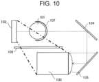
- FIG. 10 is a diagram showing that illumination light from the surface illumination light source 102 is reflected on the area camera 103, and re-illuminates the biological sample 101.
- a one-dot chain line indicates a path that connects both ends of a light-emitting surface of the surface illumination light source 102 and the outermost shape of the area camera 103 to each other.
- the path is valid (that is, the illumination light from the surface illumination light source 102 can be directly incident on the area camera 103)
- the illumination light reflected on the area camera 103 may re-illuminate the biological sample 101.
- the absorber 106 Since the reflected light has a light amount larger than that of light scattered on the absorber 106, it is desirable that the absorber 106 is also provided on the path.
- the path indicated by the one-dot chain line in FIG. 9 can be blocked, the biological sample 101 is not re-illuminated by the illumination light in FIG. 10 , but reflection may be performed a plurality of times by a mechanism component that holds an optical component, and the label 107 may be re-illuminated.
- the path indicated by the one-dot chain line in FIG. 10 is completely eliminated, whereby it is also possible to prevent such a path on which the reflection is performed a plurality of times.
- the absorber 106 may block a region sandwiched by (a) a tangent line (a one-dot chain line on a left side) in contact with both one end of the light-emitting surface of the surface illumination light source 102 and a left side surface (fifth side surface) of the area camera 103 and (b) a tangent line (a one-dot chain line on a right side) in contact with both the other end of the light-emitting surface of the surface illumination light source 102 and a right side surface (sixth side surface) of the area camera 103 in FIG. 10 .
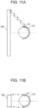
- FIG. 11A is a diagram illustrating that the surface illumination light source 102 directly illuminates a location where the transmitted light is emitted.
- the surface illumination light source 102 When the light-emitting surface of the surface illumination light source 102 is large, a region on the biological sample 101 to be imaged by the area camera 103 is directly illuminated by the surface illumination light source 102. That is, a location where the transmitted light from the biological sample 101 is emitted from the biological sample 101 is directly illuminated by the surface illumination light source 102.
- a one-dot chain line indicates a path of such direct illumination. Like the re-illumination light, the path also causes a reduction in the contrast of the measurement target region 109.
- FIG. 11B is a diagram illustrating a method for preventing the surface illumination light source 102 from directly illuminating an imaging range.
- the light-emitting surface of the surface illumination light source 102 has a size the same as that of the biological sample 101, it is possible to prevent the region on the biological sample 101 to be imaged by the area camera 103 from being directly illuminated. Therefore, it is desirable that the light-emitting surface of the surface illumination light source 102 has a size equivalent to that of the biological sample 101.
- the light-emitting surface of the surface illumination light source 102 may be made larger than the biological sample 101 by the positional deviation.
- the light-emitting surface is slightly larger than the biological sample 101 as shown in FIG. 11B , a direct illumination path similar to that indicated by the one-dot chain line in FIG. 11A may be generated. Therefore, it is desirable to take measures such as making the size of the light-emitting surface slightly larger than the biological sample 101 in consideration of the positional deviation of the component, and having the image processing unit 108 analyze a captured image only in a range of an image captured by the area camera 103 where the direct illumination light does not enter.
- a certain size is required for a planar size (a size in an upper-lower direction in FIG. 11A , or a size in a depth direction in FIG. 4 ) of the light-emitting surface of the surface illumination light source 102.
- a certain size is required for a planar size (a size in an upper-lower direction in FIG. 11A , or a size in a depth direction in FIG. 4 ) of the light-emitting surface of the surface illumination light source 102.
- a certain size is required for a planar size (a size in an upper-lower direction in FIG. 11A , or a size in a depth direction in FIG. 4 ) of the light-emitting surface of the surface illumination light source 102.
- a width of the light-emitting surface can be set at 19.2 mm as calculated above. Therefore, it is possible to achieve both necessary sizes of the light-emitting surface from viewpoints of the working distance and preventing the direct illumination light.
- the area camera 103 having a working distance of 125 mm is assumed as described above, it can be said that it is best to set an outer shape of the light-emitting surface at about 120 ⁇ 19.2 mm.
- the biological sample measuring device 100 images the transmitted light transmitted through the biological sample 101 by the area camera 103 (a camera that captures a two-dimensional image of the biological sample 101), and further includes the first mirror 104 and the second mirror 105 that refract the transmitted light to guide the transmitted light to the area camera 103.
- An optical system using the area camera 103 can eliminate a need for a large-sized mechanism such as scanning the biological sample 101 in a vertical direction. Further, the optical system using the two mirrors can improve a degree of freedom in designing the size and the wiring direction of the biological sample measuring device 100 while maintaining the working distance. Accordingly, the biological sample measuring device 100 can be miniaturized.
- the biological sample measuring device 100 can be additionally mounted as an option on a product such as an existing centrifuge.
- the biological sample measuring device 100 is not only optionally mounted, but also can be used as an independent device.
- the biological sample measuring device 100 In the biological sample measuring device 100 according to present Embodiment 1, (a) the light reflected on the second mirror 105 and directed toward the biological sample 101, (b) the light scattered from the biological sample 101, incident on the area camera 103, reflected on the area camera 103, and returned to the biological sample 101, (c) the light radiated directly from the surface illumination light source 102 to the area camera 103, reflected on the area camera 103, and directed toward the biological sample 101, and the like are blocked by the absorber 106. Accordingly, it is possible to prevent the image contrast of the measurement target region 109 from decreasing due to the re-illumination. Particularly, the prevention effects can be remarkably exhibited in the biological sample 101 to which the label 107 is attached.
- FIG. 12 is a plan view showing a configuration of the biological sample measuring device 100 according to Embodiment 2 of the present disclosure.
- the biological sample measuring device 100 can be sufficiently miniaturized, and the biological sample measuring device 100 can be mounted as an additional option on an existing device such as a centrifugal separator. That is, the components of the biological sample measuring device 100 can be mounted inside a relatively small-sized housing 1202. Further, when an arrangement between the first mirror 104 and the second mirror 105 is adjusted, an arrangement and a size of each component of the biological sample measuring device 100 can also be adjusted such that the components can be mounted in the housing 1202.
- the biological sample measuring device 100 may include a carry-in port 1201 for introducing the biological sample 101.
- the arrangement between the first mirror 104 and the second mirror 105 may be changed according to a carry-in path of the biological sample 101.
- the carry-in path there are a method for taking in and out a specimen by preparing the carry-in port (opening) in a side surface of the device as shown in FIG. 12 , a method for taking in and out the specimen from an upper portion by preparing an opening in the upper portion of the device, and the like.
- a method for gripping and moving the biological sample 101 there are a method for gripping and moving the biological sample 101 by a gripping mechanism that grips a cap region of a container, a method for placing a container on a holder and moving the container by a belt conveyor system, and the like.
- FIG. 13 is a plan view showing a configuration of the biological sample measuring device 100 according to Embodiment 3 of the present disclosure.
- the biological sample measuring device 100 according to present Embodiment 3 does not include the second mirror 105. Therefore, the first mirror 104 directly reflects the transmitted light toward the area camera 103.
- a method for specifying the measurement target region 109 is similar to those in Embodiments 1 to 2. Also in present Embodiment 3, it is desirable to block the re-illumination light or the like by the absorber 106.
- a one-dot chain line indicates a path on which light scattered on the biological sample 101 illuminates the area camera 103.
- a two-dot chain line indicates a path on which the surface illumination light source 102 directly illuminates the area camera 103. Both paths are scattered and reflected by the area camera 103, and the biological sample 101 is re-illuminated.
- re-illumination light can be blocked by disposing the absorber 106 as described in FIG. 9 .
- reflected light can be blocked by disposing the absorber 106 as described in FIG. 10 .
- the biological sample measuring device 100 according to present Embodiment 3 can have a simple configuration.
- the size of the biological sample measuring device 100 becomes larger, but when there is sufficient space, the configuration of present Embodiment 3 is also useful.
- the biological sample measuring device 100 according to the present disclosure can also be mounted as an additional option of an existing device in the existing device as described in Embodiment 2, or the biological sample measuring device 100 can also be used alone.
Landscapes
- Physics & Mathematics (AREA)
- Health & Medical Sciences (AREA)
- Life Sciences & Earth Sciences (AREA)
- Spectroscopy & Molecular Physics (AREA)
- Chemical & Material Sciences (AREA)
- Biochemistry (AREA)
- General Physics & Mathematics (AREA)
- Immunology (AREA)
- Pathology (AREA)
- Analytical Chemistry (AREA)
- General Health & Medical Sciences (AREA)
- Engineering & Computer Science (AREA)
- Mathematical Physics (AREA)
- Theoretical Computer Science (AREA)
- Biomedical Technology (AREA)
- Urology & Nephrology (AREA)
- Food Science & Technology (AREA)
- Medicinal Chemistry (AREA)
- Molecular Biology (AREA)
- Hematology (AREA)
- Investigating Or Analysing Materials By Optical Means (AREA)
Abstract
Description
- The present disclosure relates to a device that measures a biological sample separated into a plurality of component regions.
- For the purpose of improving efficiency of clinical tests such as blood tests, there is a demand for a technique for automating a related-art liquid amount checking operation of a biological specimen before opening (before dispensing) performed by visual checking. Particularly, a biological sample such as a blood specimen before dispensing is separated into a plurality of layers by centrifugal separation or the like, and a technique for measuring only a liquid amount of a sample that is an analysis target is required. Further, since a barcode label for identification or a pre-label attached to a blood collection tube and shipped may be attached to the biological sample before dispensing, there is a demand for a technique capable of performing measurement in a state where the labels are attached.
- As such a biological sample measuring device, for example,
Patent Literature 1 discloses a technique in which pulsed light having two wavelengths is radiated by performing switching in a time-division manner to a sample separated into a plurality of layers, and transmitted light is measured while scanning the sample in a vertical direction, thereby detecting a height of a predetermined region of the sample separated into the plurality of layers. -
Patent Literature 2 discloses a liquid detection device in which infrared light is applied to a specimen to detect transmitted light by a line sensor, a boundary of a label is obtained based on a first-order differential value thereof, and a serum amount of the specimen is measured. Further, inPatent Literature 2, a signal of the transmitted light is acquired by changing a light amount, so that analysis can be performed regardless of presence or absence of attenuation of the transmitted light due to the label. -
- PTL 1:
US2012/0013889 - PTL2:
JP2004-037322A - The technique disclosed in
Patent Literature 1 relates to a liquid amount measurement technique in which, for the biological sample including the plurality of components, a boundary of a measurement target region is accurately specified to measure a liquid amount based on signals of the transmitted light having two wavelengths with different absorptances for a measurement target. However, inPatent Literature 1, it is necessary to perform measurement while vertically scanning a specimen (blood collection tube) in a longitudinal direction, and there is a problem that it is difficult to miniaturize the device due to a scanning mechanism. - In the technique disclosed in
Patent Literature 2, an upper surface and a lower surface of serum are detected to measure a serum amount by signal processing based on differentiation from a signal of transmitted infrared light. However, when infrared rays are absorbed or scattered by characters printed on a blood collection tube, a blood cell component in a separating agent, color characters on a label, and the like, and the transmitted light is attenuated, there is a problem that it is difficult to separate the noises from a boundary of the serum, and accuracy of specifying the boundary of the serum and measuring a liquid amount may decrease. - The present disclosure has been made in view of the problem described above, and an object thereof is to provide a technique in which, when measuring a biological sample stored in a container to which a label is attached and separated into a plurality of component regions, a target portion that is a measurement target can be accurately specified without using a large-sized imaging mechanism.
- In a biological sample measuring device according to the present disclosure, a mirror is disposed on an optical path from a surface light source to an area camera, so that light transmitted through a biological sample is guided into the area camera while being refracted, and a light-absorbing material is disposed at a position where reflected light reflected and returned toward the biological sample is blocked.
- According to a biological sample measuring device of the present disclosure, it is possible to accurately specify a target portion that is a measurement target without using a large-sized imaging mechanism when measuring a biological sample stored in a container to which a label is attached and separated into a plurality of component regions.
-
- [
FIG. 1] FIG. 1 is a plan view showing a configuration of a biological sample measuringdevice 100 according toEmbodiment 1. - [
FIG. 2A] FIG. 2A is a diagram illustrating a principle for specifying a measurement target region. - [
FIG. 2B] FIG. 2B is a diagram illustrating a principle for specifying the measurement target region. - [
FIG. 3A] FIG. 3A shows a configuration of animage processing unit 108. - [
FIG. 3B] FIG. 3B is a flowchart illustrating an example of processing of specifying ameasurement target region 109 from transmission images and calculating a liquid amount thereof by theimage processing unit 108. - [
FIG. 4] FIG. 4 is a diagram illustrating a working distance of anarea camera 103. - [
FIG. 5A] FIG. 5A shows an example in which alabel 107 is attached to a container of abiological sample 101. - [
FIG. 5B] FIG. 5B shows an example in which thelabel 107 is attached to the container of thebiological sample 101. - [
FIG. 6A] FIG. 6A is a diagram illustrating a problem related to re-illumination. - [
FIG. 6B] FIG. 6B is a diagram illustrating a problem related to the re-illumination. - [
FIG. 7A] FIG. 7A is a diagram showing re-illumination light from asecond mirror 105. - [
FIG. 7B] FIG. 7B is a diagram illustrating a method for preventing the re-illumination light from thesecond mirror 105. - [
FIG. 8] FIG. 8 shows a modification of anabsorber 106. - [
FIG. 9] FIG. 9 is a diagram showing that scattered light from thelabel 107 is reflected on thearea camera 103 and re-illuminates thebiological sample 101. - [
FIG. 10] FIG. 10 is a diagram showing that illumination light from a surfaceillumination light source 102 is reflected on thearea camera 103 and re-illuminates thebiological sample 101. - [
FIG. 11A] FIG. 11A is a diagram showing that the surfaceillumination light source 102 directly illuminates a location where transmitted light is emitted. - [
FIG. 11B] FIG. 11B is a diagram illustrating a method for preventing the surfaceillumination light source 102 from directly illuminating an imaging range. - [
FIG. 12] FIG. 12 is a plan view showing a configuration of the biologicalsample measuring device 100 according toEmbodiment 2. - [
FIG. 13] FIG. 13 is a plan view showing a configuration of the biologicalsample measuring device 100 according to Embodiment 3. - A biological sample to be measured in
Embodiment 1 of the present disclosure is a specimen to which a pre-opening (pre-analysis) label is attached, and is assumed to be separated into a plurality of component layers (typically, one to three layers) depending on presence or absence of centrifugal separation. A measurement target is a portion that is an analysis target (that is a dispensing target) by a biochemical analyzer or the like such as plasma or serum of a specimen separated into a plurality of layers. -
FIG. 1 is a plan view showing a configuration of a biologicalsample measuring device 100 according toEmbodiment 1 of the present disclosure. The biologicalsample measuring device 100 is a device that measures abiological sample 101. Thebiological sample 101 is a sample configured as described above. The biologicalsample measuring device 100 specifies a measurement target region of thebiological sample 101, and measures a liquid amount thereof. The biologicalsample measuring device 100 includes a surfaceillumination light source 102, anarea camera 103, afirst mirror 104, asecond mirror 105, anabsorber 106, and animage processing unit 108. - The surface
illumination light source 102 switches a wavelength of emitted light between two wavelengths, and illuminates thebiological sample 101 with the light. The light emitted from the surfaceillumination light source 102 can simultaneously illuminate two or more component layers (that is, across two or more component layers) that constitute thebiological sample 101. Further, regardless of the component layer, an upper surface of an uppermost layer (a boundary between the sample and an air layer) can be radiated. Switching a wavelength of light does not necessarily require emitting light having only a single wavelength, and it is sufficient that a wavelength component having a highest intensity can be switched (wavelength λ1 = 1550 ± 100 nm, wavelength λ2 = 970 ± 100 nm, or the like). In thebiological sample 101 having one or three component layers, when the number of the component layers is known before measurement, it is sufficient to use either of the two wavelengths, and there is no need to switch a wavelength. A reason and a method for selecting a wavelength will be described in a measurement principle to be described later. - The
area camera 103 images surface illumination light transmitted through thebiological sample 101, thereby generating a two-dimensional captured image of thebiological sample 101. Thearea camera 103 has sensitivity characteristics that can detect light in a wavelength band emitted from the surfaceillumination light source 102. Thearea camera 103 can be implemented by, for example, an InGaAs camera. - The
first mirror 104 reflects the transmitted light transmitted through thebiological sample 101 toward thesecond mirror 105. Thesecond mirror 105 reflects the transmitted light reflected on thefirst mirror 104 toward thearea camera 103. Accordingly, the transmitted light is reflected twice from transmitted through thebiological sample 101 until reaching thearea camera 103, and the optical path is refracted twice due to the reflection. - The
absorber 106 has characteristics of attenuating a light amount of the transmitted light transmitted through thebiological sample 101 by at least partially absorbing the transmitted light transmitted through thebiological sample 101. A size and an arrangement of theabsorber 106 will be described later. - The
image processing unit 108 extracts the measurement target region (an image region of the specimen) from the captured image acquired by thearea camera 103. An extraction principle will be described below. -
FIGS. 2A and 2B are diagrams illustrating a principle for specifying the measurement target region. In the configuration inFIG. 1 , thearea camera 103 captures a two-dimensional transmission image of thebiological sample 101 as shown inFIGS. 2A and 2B . -
FIG. 2A shows an example in which thebiological sample 101 is separated into three layers.FIG. 2B shows an example in which thebiological sample 101 is separated into two layers. Ablood clot 202 is formed at a lower layer when thebiological sample 101 is centrifugally separated. A separatingagent 201 is mixed to separate theblood clot 202 from themeasurement target region 109. - When a first wavelength (wavelength 1) and a second wavelength (wavelength 2) emitted from the surface
illumination light source 102 are compared, a transmittance when thewavelength 1 is transmitted through theblood clot 202 and a transmittance when thewavelength 2 is transmitted through theblood clot 202 are substantially the same. Therefore, a difference between a captured image of theblood clot 202 acquired using thewavelength 1 and a captured image of theblood clot 202 acquired using thewavelength 2 is very small. Similarly, for the separatingagent 201, since the transmittance of thewavelength 1 and the transmittance of thewavelength 2 are substantially the same, a difference between the two images is very small. - In contrast, a transmittance when the
wavelength 1 is transmitted through themeasurement target region 109 and a transmittance when thewavelength 2 is transmitted through themeasurement target region 109 are greatly different. Therefore, a difference between a captured image of themeasurement target region 109 acquired using thewavelength 1 and a captured image of themeasurement target region 109 acquired using thewavelength 2 is remarkable. The difference is identified, whereby themeasurement target region 109 can be extracted from the captured images. - Wavelength bands adopted as the
wavelength 1 and thewavelength 2 need to be selected in advance such that a remarkable difference is generated between the wavelengths in themeasurement target region 109, but almost no difference is generated in other portions as exemplified inFIGS. 2A and 2B . As long as the condition is satisfied, a specific numerical value of a wavelength may be optional. That is, at least a difference between the transmittance when thewavelength 1 is transmitted through themeasurement target region 109 and the transmittance when thewavelength 2 is transmitted through themeasurement target region 109 just needs to be larger than a difference between a transmittance when thewavelength 1 is transmitted through a region other than themeasurement target region 109 and a transmittance when thewavelength 2 is transmitted through a region other than themeasurement target region 109. - By using the measurement principle described above, when the
biological sample 101 is separated into a plurality of component layers, themeasurement target region 109 can be specified. Theimage processing unit 108 specifies themeasurement target region 109 according to the principle. Although the number of component layers does not matter, a typical biological sample such as plasma or serum is separated into one to three layers. In either case, themeasurement target region 109 can be accurately specified. - Regarding the
biological sample 101 having one component layer and thebiological sample 101 having three component layers, when the number of component layers is known in advance before the measurement, measurement can be performed using a transmission image having only one wavelength. In a case of three layers as shown inFIG. 2A , a wavelength having a difference in an absorptance between the air layer and the separatingagent 201 located above and below themeasurement target region 109 and themeasurement target region 109 may be selected. In a case of one layer, a wavelength having a difference between the air layer above themeasurement target region 109 and an absorptance of themeasurement target region 109 may be selected. -
FIG. 3A shows a configuration of theimage processing unit 108. Theimage processing unit 108 analyzes a captured image having each wavelength acquired by thearea camera 103. Theimage processing unit 108 includes animage acquisition unit 1081, a measurement targetregion specifying unit 1082, and a liquidamount calculation unit 1083. Theimage acquisition unit 1081 acquires transmission images having two wavelengths captured by thearea camera 103. The measurement targetregion specifying unit 1082 specifies themeasurement target region 109 by comparing the captured images having the wavelengths. The liquidamount calculation unit 1083 calculates a liquid amount in themeasurement target region 109. -
FIG. 3B is a flowchart illustrating an example of processing of specifying themeasurement target region 109 from the transmission images and calculating a liquid amount thereof by theimage processing unit 108. Hereinafter, steps inFIG. 3B will be described. - The measurement target
region specifying unit 1082 acquires the captured images at thewavelength 1 and thewavelength 2. In the present flowchart, since it is sufficient that themeasurement target region 109 can be specified according to the procedure illustrated inFIGS. 2A and 2B , exposure time may use, for example, a value predetermined as a specified value. - The measurement target
region specifying unit 1082 calculates a difference image between the captured image at thewavelength 1 and the captured image at thewavelength 2. In the present step, the difference image illustrated inFIGS. 2A and 2B is calculated, and the difference image can be acquired by calculating a difference in pixel values of the images. Examples of a calculation procedure include the following: (a)wavelength 1 image -wavelength 2 image; (b)wavelength 2 image -wavelength 1 image; and (c) (wavelength 1 image -wavelength 2 image)/(wavelength 1 image +wavelength 2 image). - In a case where the number of component layers of the
biological sample 101 is one or three, when a transmission image having one wavelength is analyzed without switching the wavelength, the present step is omitted, and a boundary of each layer is specified using processing such as edge detection in S305. - The measurement target
region specifying unit 1082 sets a threshold for detecting themeasurement target region 109. The threshold can be set as, for example, a pixel value = 0, or an appropriate threshold may be set for each sample. - The measurement target
region specifying unit 1082 extracts, as themeasurement target region 109, a portion of the difference image whose pixel value is equal to or larger than the threshold. - The measurement target
region specifying unit 1082 detects an edge (height) of themeasurement target region 109. As an edge detection method, for example, the following can be used: (a) an edge detection algorithm based on a luminance gradient (inclination), a differential value, or the like in a vertical direction; (b) pixel values of the extractedmeasurement target region 109 are integrated in a horizontal direction to be one-dimensional, and an edge in a perpendicular direction is specified using a signal inclination, a differential value, a variance value, or the like in the perpendicular direction. A specification result can be stored as coordinate values on a captured image. That is, statistics of the pixel values in the horizontal direction are calculated as feature values in the horizontal direction, and the feature values are compared along the vertical direction, whereby upper and lower edges of themeasurement target region 109 can be specified. - The liquid
amount calculation unit 1083 can calculate a liquid amount in themeasurement target region 109 by using a result in the present step. For example, after boundaries of the layers are specified, a liquid amount in a corresponding region is calculated using information on a pixel pitch, the number of extracted pixels, and an inner diameter of a container of thebiological sample 101. -
FIG. 4 is a diagram illustrating a working distance of thearea camera 103. In order to measure a liquid amount based on the transmission image of thebiological sample 101 as shown inFIG. 2 , it is necessary to secure a field of view in a longitudinal direction capable of imaging the boundaries of the layers of thebiological sample 101. For that purpose, it is necessary to sufficiently secure the working distance (a distance from thebiological sample 101 to a lens of the area camera 103). - The necessary working distance is obtained using a focal length of the lens, a necessary field of view, and a sensor size. When the necessary field of view is 100 mm that is a length of a blood collection tube (specimen container), the focal length is 8 mm, and the sensor size is 6.4 mm (long side), the working distance is 125 m. That is, in order to image the entire biological sample, it is necessary to dispose the
biological sample 101 and thearea camera 103 by a distance of 125 mm. - In
FIG. 1 , the optical path of the transmitted light is folded back by using the two mirrors. The configuration in which the optical path is refracted is adopted as described above, whereby a sufficient working distance can be secured while reducing an area size of the biologicalsample measuring device 100. Further, a size of the biologicalsample measuring device 100 can be changed according to an application by an arrangement of the mirrors. - It is desirable that the surface
illumination light source 102 has a size of a region sandwiched by lines that connect an outermost shape of thebiological sample 101 to a center of thearea camera 103. Therefore, it is desirable that a size of the surfaceillumination light source 102 in an upper-lower direction in the drawing inFIG. 4 secures the size of the region sandwiched by the lines that connect the outermost shape shown inFIG. 4 . For example, when the working distance is 125 mm, the length of the blood collection tube is 100 mm, and a distance between the illuminator and the area camera is 150 mm, it is desirable that a height (the size in the upper-lower direction in the drawing inFIG. 4 ) of the surfaceillumination light source 102 is 120 mm based on a similarity relationship of a triangle. -
FIGS. 5A and 5B show an example in which alabel 107 is attached to a container of thebiological sample 101.FIG. 5A is a side view of the container, andFIG. 5B is a top view thereof. A barcode label, a pre-label, or the like may be attached to the container (for example, a blood collection tube) of thebiological sample 101. Even in such a case, it is required to accurately specify themeasurement target region 109. - When a mechanism that controls an orientation of the
biological sample 101 is not provided, there are a case where the label is on an illuminator side ((1) inFIG. 5B ) and a case where the label is on a side opposite to the illuminator ((2) inFIG. 5B ). In either case, it is required to specify the measurement target region with the same accuracy. -
FIGS. 6A and 6B are diagrams illustrating a problem related to re-illumination. Under the condition of the label as shown inFIG. 5 , a problem related to re-illumination of the transmitted light occurs. When miniaturization is implemented by using the two mirrors as shown inFIG. 1 , light scattered and transmitted from thebiological sample 101 is reflected on thesecond mirror 105, and re-illumination light that illuminates a sample surface on a side opposite to the surfaceillumination light source 102 is generated via an optical path as indicated by solid lines inFIG. 6A . - At this time, as shown in (1) in
FIG. 5B , when thelabel 107 is on the illuminator side and thelabel 107 is not on afirst mirror 104 side, a transmission image as shown in (1) inFIG. 6B is obtained. Under such a condition, a boundary contrast sufficient for specifying the measurement target region is obtained. On the other hand, when thelabel 107 is on thefirst mirror 104 side as shown in (2) inFIG. 5B , the re-illumination light is reflected on thelabel 107, and both the transmitted light of thebiological sample 101 and the reflected light of thelabel 107 are imaged. In a case of thelabel 107 having high reflectivity such as white, when there is light that reflects thelabel 107, a label image is obtained as shown in (2) inFIG. 6B . Such reflected light of thelabel 107 reduces contrast of the transmitted light necessary for specifying themeasurement target region 109. - A similar problem related to the re-illumination also occurs, when the surface
illumination light source 102 directly radiates the area camera 103 (an arrow directed from the surfaceillumination light source 102 toward thearea camera 103 inFIG. 6A ) and light reflected on thearea camera 103 illuminates the biological sample 101 (an arrow directed from thearea camera 103 toward thebiological sample 101 inFIG. 6A ). - As described above, even for the same
biological sample 101, images obtained when an orientation of the biological sample 101 (an orientation of the label 107) is changed are different. Further, when a reduction in the contrast due to the re-illumination light is remarkable, accuracy of specifying themeasurement target region 109 decreases. That is, analysis accuracy decreases depending on an orientation of thebiological sample 101. In order to solve such a problem, the size and the arrangement of theabsorber 106 are implemented as follows inpresent Embodiment 1. -
FIG. 7A is a diagram showing re-illumination light from thesecond mirror 105. A dotted line indicates an optical path of effective light flux necessary for acquiring an image of thebiological sample 101 by thearea camera 103. A one-dot chain line indicates a line where a normal line of thesecond mirror 105 overlaps thebiological sample 101. When a path of the one-dot chain line is valid (that is, the transmitted light can reach thebiological sample 101 via the path), light scattered on thelabel 107 is reflected on thesecond mirror 105, and re-illumination light that re-illuminates thelabel 107 is generated. -
FIG. 7B is a diagram illustrating a method for preventing the re-illumination light from thesecond mirror 105. As described above, since the working distance is determined based on the field of view necessary for analysis, the sensor size of thearea camera 103, and the focal length of the lens, it is not possible to prevent the re-illumination light by changing a distance between thearea camera 103 and thebiological sample 101. Therefore, while maintaining the working distance, thefirst mirror 104 and thesecond mirror 105 are separated from thebiological sample 101, and an interval between thearea camera 103 and thesecond mirror 105 is shortened. Accordingly, an arrangement relationship as shown inFIG. 7B is established while maintaining the working distance. - In
FIG. 7B , theabsorber 106 blocks the re-illumination light by disposing theabsorber 106 on the optical path indicated by the one-dot chain line. That is, the size and the arrangement position of theabsorber 106 block the transmitted light reflected on thesecond mirror 105 from re-illuminating the biological sample 101 (more specifically, the label 107). Accordingly, it is possible to solve the problem of the re-illumination described inFIG. 6A . - It is desirable that the
absorber 106 does not block the transmitted light reflected from thefirst mirror 104 toward thesecond mirror 105. InFIG. 7B , theabsorber 106 is disposed such that a right end of theabsorber 106 does not overlap a straight line that connects a left end of thefirst mirror 104 to a left end of thesecond mirror 105. Accordingly, theabsorber 106 can block only the path of the re-illumination light indicated by the one-dot chain line without obstructing the path of the effective light flux indicated by the dotted line. - The arrangement in
FIG. 7B also has the following advantages. In a related-art arrangement relationship between the surfaceillumination light source 102 and thearea camera 103 as shown inFIG. 4 , since wiring that supplies power to the surfaceillumination light source 102 extends to a left side of the drawing, and wiring that supplies the power to thearea camera 103 extends to a right side of the drawing, a size of a space for housing the wiring is increased. In contrast, in the arrangement relationship inFIG. 7B , since either wiring extends to a left side of the drawing, it is possible to reduce the size of the space for housing the wiring. In other words, it is desirable that the surfaceillumination light source 102 and thearea camera 103 are disposed such that a direction in which the surfaceillumination light source 102 emits light and a direction of light when thearea camera 103 receives light are parallel to each other, and face the same orientation. -
FIG. 8 shows a modification of theabsorber 106. The shape of theabsorber 106 does not necessarily have to be planar. For example, theabsorber 106 may have a bent shape obtained by being refracted at one or more locations as shown inFIG. 8 (that is, two or more portions that block the optical path indicated by the one-dot chain line may be provided). When theabsorber 106 is bent, it is easier to create an interval between the path of the effective light flux indicated by the dotted line and theabsorber 106. This is because even if the interval is created, it is sufficient that at least one of the bent portions blocks the one-dot chain line. Accordingly, effects of facilitating product design in consideration of a positional deviation of a component are obtained. -
FIG. 9 is a diagram showing that scattered light from thelabel 107 is reflected on thearea camera 103 and re-illuminates thebiological sample 101. A one-dot chain line indicates a path that connects the outermost shape of thebiological sample 101 and an outermost shape of thearea camera 103 to each other. When the path is valid (that is, the scattered light from thelabel 107 can be reflected on thearea camera 103, and can reach thebiological sample 101 via the path), the light scattered on thelabel 107 re-illuminates thebiological sample 101. Theabsorber 106 may obstruct the path. - Specifically, the
absorber 106 may block a region sandwiched by (a) a tangent line (a one-dot chain line on a left side) in contact with both a left side surface (first side surface) of the biological sample 101 (specimen container) and a left side surface (second side surface) of thearea camera 103 and (b) a tangent line (a one-dot chain line on a right side) in contact with both a right side surface (third side surface) of thebiological sample 101 and a right side surface (fourth side surface) of thearea camera 103 inFIG. 9 . -
FIG. 10 is a diagram showing that illumination light from the surfaceillumination light source 102 is reflected on thearea camera 103, and re-illuminates thebiological sample 101. A one-dot chain line indicates a path that connects both ends of a light-emitting surface of the surfaceillumination light source 102 and the outermost shape of thearea camera 103 to each other. When the path is valid (that is, the illumination light from the surfaceillumination light source 102 can be directly incident on the area camera 103), the illumination light reflected on thearea camera 103 may re-illuminate thebiological sample 101. - Since the reflected light has a light amount larger than that of light scattered on the
absorber 106, it is desirable that theabsorber 106 is also provided on the path. When the path indicated by the one-dot chain line inFIG. 9 can be blocked, thebiological sample 101 is not re-illuminated by the illumination light inFIG. 10 , but reflection may be performed a plurality of times by a mechanism component that holds an optical component, and thelabel 107 may be re-illuminated. The path indicated by the one-dot chain line inFIG. 10 is completely eliminated, whereby it is also possible to prevent such a path on which the reflection is performed a plurality of times. - Specifically, the
absorber 106 may block a region sandwiched by (a) a tangent line (a one-dot chain line on a left side) in contact with both one end of the light-emitting surface of the surfaceillumination light source 102 and a left side surface (fifth side surface) of thearea camera 103 and (b) a tangent line (a one-dot chain line on a right side) in contact with both the other end of the light-emitting surface of the surfaceillumination light source 102 and a right side surface (sixth side surface) of thearea camera 103 inFIG. 10 . -
FIG. 11A is a diagram illustrating that the surfaceillumination light source 102 directly illuminates a location where the transmitted light is emitted. When the light-emitting surface of the surfaceillumination light source 102 is large, a region on thebiological sample 101 to be imaged by thearea camera 103 is directly illuminated by the surfaceillumination light source 102. That is, a location where the transmitted light from thebiological sample 101 is emitted from thebiological sample 101 is directly illuminated by the surfaceillumination light source 102. A one-dot chain line indicates a path of such direct illumination. Like the re-illumination light, the path also causes a reduction in the contrast of themeasurement target region 109. -
FIG. 11B is a diagram illustrating a method for preventing the surfaceillumination light source 102 from directly illuminating an imaging range. When the light-emitting surface of the surfaceillumination light source 102 has a size the same as that of thebiological sample 101, it is possible to prevent the region on thebiological sample 101 to be imaged by thearea camera 103 from being directly illuminated. Therefore, it is desirable that the light-emitting surface of the surfaceillumination light source 102 has a size equivalent to that of thebiological sample 101. - However, in consideration of a positional deviation of a component, the light-emitting surface of the surface
illumination light source 102 may be made larger than thebiological sample 101 by the positional deviation. In this case, since the light-emitting surface is slightly larger than thebiological sample 101 as shown inFIG. 11B , a direct illumination path similar to that indicated by the one-dot chain line inFIG. 11A may be generated. Therefore, it is desirable to take measures such as making the size of the light-emitting surface slightly larger than thebiological sample 101 in consideration of the positional deviation of the component, and having theimage processing unit 108 analyze a captured image only in a range of an image captured by thearea camera 103 where the direct illumination light does not enter. - On the other hand, for a planar size (a size in an upper-lower direction in
FIG. 11A , or a size in a depth direction inFIG. 4 ) of the light-emitting surface of the surfaceillumination light source 102, a certain size is required. Specifically, as described inFIG. 4 , it is desirable that the region sandwiched by the lines that connect the outermost shape of thebiological sample 101 to the center of thearea camera 103 has a certain size. For example, when the working distance is 1 mm, the width of the specimen container is 16 mm, and the distance from the surfaceillumination light source 102 to thearea camera 103 is 150 mm, the planar size of the light-emitting surface is 19.2 mm based on the similarity relationship of the triangle. - As shown in
FIG. 11A , since the direct illumination light hits an edge of the specimen container when the light-emitting surface is larger than the specimen container, the portion is excluded from the analysis range of theimage processing unit 108. Accordingly, a width of the light-emitting surface can be set at 19.2 mm as calculated above. Therefore, it is possible to achieve both necessary sizes of the light-emitting surface from viewpoints of the working distance and preventing the direct illumination light. When thearea camera 103 having a working distance of 125 mm is assumed as described above, it can be said that it is best to set an outer shape of the light-emitting surface at about 120 × 19.2 mm. - The biological
sample measuring device 100 according topresent Embodiment 1 images the transmitted light transmitted through thebiological sample 101 by the area camera 103 (a camera that captures a two-dimensional image of the biological sample 101), and further includes thefirst mirror 104 and thesecond mirror 105 that refract the transmitted light to guide the transmitted light to thearea camera 103. An optical system using thearea camera 103 can eliminate a need for a large-sized mechanism such as scanning thebiological sample 101 in a vertical direction. Further, the optical system using the two mirrors can improve a degree of freedom in designing the size and the wiring direction of the biologicalsample measuring device 100 while maintaining the working distance. Accordingly, the biologicalsample measuring device 100 can be miniaturized. For example, the biologicalsample measuring device 100 can be additionally mounted as an option on a product such as an existing centrifuge. Of course, the biologicalsample measuring device 100 is not only optionally mounted, but also can be used as an independent device. - In the biological
sample measuring device 100 according topresent Embodiment 1, (a) the light reflected on thesecond mirror 105 and directed toward thebiological sample 101, (b) the light scattered from thebiological sample 101, incident on thearea camera 103, reflected on thearea camera 103, and returned to thebiological sample 101, (c) the light radiated directly from the surfaceillumination light source 102 to thearea camera 103, reflected on thearea camera 103, and directed toward thebiological sample 101, and the like are blocked by theabsorber 106. Accordingly, it is possible to prevent the image contrast of themeasurement target region 109 from decreasing due to the re-illumination. Particularly, the prevention effects can be remarkably exhibited in thebiological sample 101 to which thelabel 107 is attached. -
FIG. 12 is a plan view showing a configuration of the biologicalsample measuring device 100 according toEmbodiment 2 of the present disclosure. When the configuration described inEmbodiment 1 is adopted, the biologicalsample measuring device 100 can be sufficiently miniaturized, and the biologicalsample measuring device 100 can be mounted as an additional option on an existing device such as a centrifugal separator. That is, the components of the biologicalsample measuring device 100 can be mounted inside a relatively small-sized housing 1202. Further, when an arrangement between thefirst mirror 104 and thesecond mirror 105 is adjusted, an arrangement and a size of each component of the biologicalsample measuring device 100 can also be adjusted such that the components can be mounted in thehousing 1202. - The biological
sample measuring device 100 may include a carry-inport 1201 for introducing thebiological sample 101. The arrangement between thefirst mirror 104 and thesecond mirror 105 may be changed according to a carry-in path of thebiological sample 101. - As the carry-in path, there are a method for taking in and out a specimen by preparing the carry-in port (opening) in a side surface of the device as shown in
FIG. 12 , a method for taking in and out the specimen from an upper portion by preparing an opening in the upper portion of the device, and the like. As a method for gripping and moving thebiological sample 101, there are a method for gripping and moving thebiological sample 101 by a gripping mechanism that grips a cap region of a container, a method for placing a container on a holder and moving the container by a belt conveyor system, and the like. -
FIG. 13 is a plan view showing a configuration of the biologicalsample measuring device 100 according to Embodiment 3 of the present disclosure. The biologicalsample measuring device 100 according to present Embodiment 3 does not include thesecond mirror 105. Therefore, thefirst mirror 104 directly reflects the transmitted light toward thearea camera 103. A method for specifying themeasurement target region 109 is similar to those inEmbodiments 1 to 2. Also in present Embodiment 3, it is desirable to block the re-illumination light or the like by theabsorber 106. - A one-dot chain line indicates a path on which light scattered on the
biological sample 101 illuminates thearea camera 103. A two-dot chain line indicates a path on which the surfaceillumination light source 102 directly illuminates thearea camera 103. Both paths are scattered and reflected by thearea camera 103, and thebiological sample 101 is re-illuminated. Regarding the one-dot chain line, re-illumination light can be blocked by disposing theabsorber 106 as described inFIG. 9 . Regarding the two-dot chain line, reflected light can be blocked by disposing theabsorber 106 as described inFIG. 10 . - Also in present Embodiment 3, it is desirable to dispose the
absorber 106 such that theabsorber 106 does not block effective light flux reflected from thefirst mirror 104 and directed toward thearea camera 103. Therefore, a right end of theabsorber 106 inFIG. 13 does not overlap a straight line that connects a left end of thefirst mirror 104 to a left end of an imaging surface of thearea camera 103. - As compared with a case of two mirrors described in
Embodiment 1, the biologicalsample measuring device 100 according to present Embodiment 3 can have a simple configuration. By using one mirror, when compared with a case of two mirrors, the size of the biologicalsample measuring device 100 becomes larger, but when there is sufficient space, the configuration of present Embodiment 3 is also useful. - The biological
sample measuring device 100 according to the present disclosure can also be mounted as an additional option of an existing device in the existing device as described inEmbodiment 2, or the biologicalsample measuring device 100 can also be used alone. -
- 100: biological sample measuring device
- 101: biological sample
- 102: surface illumination light source
- 103: area camera
- 104: first mirror
- 105: second mirror
- 106: absorber
- 107: label
- 108: image processing unit
- 109: measurement target region
- 201: separating agent
- 202: blood clot
Claims (15)
- A biological sample measuring device for measuring a biological sample separated into a plurality of component regions, the biological sample measuring device comprising:a surface light source configured to radiate light to the biological sample;an imager configured to generate a two-dimensional captured image of the biological sample using the light transmitted through the biological sample;a first mirror configured to reflect the light transmitted through the biological sample;a second mirror configured to reflect the light reflected on the first mirror toward the imager; andan absorber configured to absorb the light, whereinthe absorber is disposed at a position where the light is blocked on a reflection path on which the light reflected on the second mirror returns toward the biological sample.
- The biological sample measuring device according to claim 1, wherein
the absorber is disposed at a position where the light reflected from the first mirror toward the second mirror is not obstructed on a path of the light between the first mirror and the second mirror. - The biological sample measuring device according to claim 1, wherein
the absorber includes a first portion configured to block the light and a second portion configured to block the light by having a bent shape at at least one location. - The biological sample measuring device according to claim 1, whereinthe absorber is disposed at a position where the light is blocked in at least a first range of a space between the biological sample and the imager, andthe first range is a region sandwiched bya first tangent line in contact with a first side surface of a container that houses the biological sample and a second side surface of the imager, anda second tangent line in contact with a third side surface on a side opposite to the first side surface of the container and a fourth side surface on a side opposite to the second side surface of the imager.
- The biological sample measuring device according to claim 1, whereinthe absorber is disposed at a position where the light is blocked in at least a second range of a space between the surface light source and the imager, andthe second range is a region sandwiched bya third tangent line in contact with one end of a light-emitting surface of the surface light source and a fifth side surface of the imager, anda fourth tangent line in contact with the other end of the light-emitting surface and a sixth side surface on a side opposite to the fifth side surface of the imager.
- The biological sample measuring device according to claim 1, further comprising:an image processing unit configured to specify, from the captured image, a target portion that is a measurement target of the component regions, whereinthe surface light source has a size of a surface where at least a part of a location where the light transmitted through the biological sample is emitted from the biological sample is directly radiated, andthe image processing unit specifies the target portion of the captured image without using a portion generated from the light transmitted through the part.
- The biological sample measuring device according to claim 1, further comprising:an image processing unit configured to specify, from the captured image, a target portion that is a measurement target of the component regions, whereinthe imager generates a first captured image of the biological sample using a first wavelength component of the light transmitted through the biological sample,the imager generates a second captured image of the biological sample using a second wavelength component of the light transmitted through the biological sample,the image processing unit calculates a difference between a portion generated using the first wavelength component in the first captured image and a portion generated by the second wavelength component in the second captured image, andthe image processing unit specifies a range of the target portion by specifying a portion where the difference is equal to or larger than a threshold.
- The biological sample measuring device according to claim 1, further comprising:
a carry-in port through which the biological sample is introduced into the biological sample measuring device. - The biological sample measuring device according to claim 1, whereina light-emitting direction of the surface light source and a light-receiving direction of the imager are parallel to each other, andan orientation in which the surface light source emits the light and an orientation of the light when the imager receives the light are opposite to each other.
- The biological sample measuring device according to claim 1, wherein
the biological sample measuring device measures the biological sample housed in a container to which a label is attached. - A biological sample measurement method for measuring a biological sample housed in a container to which a label is attached and separated into a plurality of component regions, the biological sample measurement method comprising:a step of radiating light from a surface illumination light source to the biological sample;a step of generating a two-dimensional captured image of the biological sample by an imager using the light transmitted through the biological sample;a step of reflecting the light transmitted through the biological sample by a first mirror;a step of reflecting the light reflected on the first mirror toward the imager by a second mirror; anda step of absorbing the light by an absorber that absorbs the light, whereinthe absorber is disposed at a position where the light is blocked on a reflection path on which the light reflected on the second mirror returns toward the biological sample.
- A biological sample measuring device for measuring a biological sample separated into a plurality of component regions, the biological sample measuring device comprising:a surface light source configured to radiate light to the biological sample;an imager configured to generate a two-dimensional captured image of the biological sample using the light transmitted through the biological sample;a mirror configured to reflect the light transmitted through the biological sample toward the imager; andan absorber configured to absorb the light, whereinthe absorber is disposed at a position where the light is blocked on a reflection path on which the light scattered on or transmitted through the biological sample is reflected on the imager and returns toward the biological sample.
- The biological sample measuring device according to claim 12, wherein
the absorber is disposed at a position where the light reflected from the mirror toward the imager is not obstructed on a path of the light between the mirror and the imager. - The biological sample measuring device according to claim 12, whereinthe absorber is disposed at a position where the light is blocked in at least a first range of a space between the biological sample and the imager, andthe first range is a region sandwiched bya first tangent line in contact with a first side surface of a container that houses the biological sample and a second side surface of the imager, anda second tangent line in contact with a third side surface on a side opposite to the first side surface of the container and a fourth side surface on a side opposite to the second side surface of the imager.
- The biological sample measuring device according to claim 12, whereinthe absorber is disposed at a position where the light is blocked in at least a second range of a space between the surface light source and the imager, andthe second range is a region sandwiched bya third tangent line in contact with one end of a light-emitting surface of the surface light source and a fifth side surface of the imager, anda fourth tangent line in contact with the other end of the light-emitting surface and a sixth side surface on a side opposite to the fifth side surface of the imager.
Applications Claiming Priority (2)
| Application Number | Priority Date | Filing Date | Title |
|---|---|---|---|
| JP2021181601A JP7847968B2 (en) | 2021-11-08 | 2021-11-08 | Biological sample measuring device |
| PCT/JP2022/035467 WO2023079855A1 (en) | 2021-11-08 | 2022-09-22 | Biological sample measuring device |
Publications (2)
| Publication Number | Publication Date |
|---|---|
| EP4431912A1 true EP4431912A1 (en) | 2024-09-18 |
| EP4431912A4 EP4431912A4 (en) | 2025-10-15 |
Family
ID=86241306
Family Applications (1)
| Application Number | Title | Priority Date | Filing Date |
|---|---|---|---|
| EP22889679.1A Pending EP4431912A4 (en) | 2021-11-08 | 2022-09-22 | DEVICE FOR MEASURING BIOLOGICAL SAMPLES |
Country Status (5)
| Country | Link |
|---|---|
| US (1) | US20240410821A1 (en) |
| EP (1) | EP4431912A4 (en) |
| JP (1) | JP7847968B2 (en) |
| CN (1) | CN118043644A (en) |
| WO (1) | WO2023079855A1 (en) |
Family Cites Families (19)
| Publication number | Priority date | Publication date | Assignee | Title |
|---|---|---|---|---|
| JP2834200B2 (en) * | 1989-08-02 | 1998-12-09 | 株式会社日立製作所 | Liquid sample analyzer and analysis method |
| US6609946B1 (en) * | 2000-07-14 | 2003-08-26 | Advanced Micro Devices, Inc. | Method and system for polishing a semiconductor wafer |
| US6533641B1 (en) * | 2000-09-21 | 2003-03-18 | Advanced Micro Devices, Inc. | Grinding arrangement and method for real-time viewing of samples during cross-sectioning |
| US7274418B2 (en) * | 2003-10-21 | 2007-09-25 | Symbol Technologies, Inc. | Method and system for improving the contrast of LCDs using circular polarization |
| JP4405881B2 (en) | 2004-09-16 | 2010-01-27 | キヤノン株式会社 | Target substance detection apparatus and target substance detection method |
| JP2007057317A (en) | 2005-08-23 | 2007-03-08 | Olympus Corp | Automatic analyzer |
| JP2007225339A (en) | 2006-02-21 | 2007-09-06 | Olympus Corp | Analyzer |
| US8675187B2 (en) * | 2008-12-24 | 2014-03-18 | Hitachi High-Technologies Corporation | Photometer and analyzing system provided with photometer |
| US20110226045A1 (en) | 2009-11-25 | 2011-09-22 | Mcquillan Adrian Charles | Liquid analysis system |
| JP4742166B2 (en) | 2009-12-04 | 2011-08-10 | 株式会社日立ハイテクノロジーズ | Sample analyzer |
| CN201689063U (en) * | 2010-05-13 | 2010-12-29 | 山东大学 | Empty bottle wall defect inspection device |
| JP5330313B2 (en) | 2010-05-24 | 2013-10-30 | 株式会社日立ハイテクノロジーズ | Biological sample analyzer |
| JP5651061B2 (en) | 2011-03-31 | 2015-01-07 | 富士フイルム株式会社 | Biomolecule detection apparatus and biomolecule detection method |
| JP6302771B2 (en) | 2014-06-30 | 2018-03-28 | 株式会社日立製作所 | Optical detection device |
| US11815519B2 (en) * | 2017-07-19 | 2023-11-14 | Siemens Healthcare Diagnostics Inc. | Stray light compensating methods and apparatus for characterizing a specimen |
| JP6983997B2 (en) | 2017-07-31 | 2021-12-17 | シーメンス・ヘルスケア・ダイアグノスティックス・インコーポレーテッドSiemens Healthcare Diagnostics Inc. | Methods and equipment for assessing the properties of a sample or sample container |
| CN112041076B (en) | 2018-04-23 | 2023-04-18 | 迈恩医疗解决方案有限公司 | Automatic analyzer and optical measuring method for obtaining a measuring signal from a liquid medium |
| US11386551B2 (en) | 2018-11-08 | 2022-07-12 | Perkinelmer Health Sciences, Inc. | Method and apparatus for buffy coat imaging |
| JP7041240B2 (en) | 2020-12-10 | 2022-03-23 | 株式会社日立ハイテク | Biological sample analyzer |
-
2021
- 2021-11-08 JP JP2021181601A patent/JP7847968B2/en active Active
-
2022
- 2022-09-22 CN CN202280066630.1A patent/CN118043644A/en active Pending
- 2022-09-22 WO PCT/JP2022/035467 patent/WO2023079855A1/en not_active Ceased
- 2022-09-22 US US18/698,829 patent/US20240410821A1/en active Pending
- 2022-09-22 EP EP22889679.1A patent/EP4431912A4/en active Pending
Also Published As
| Publication number | Publication date |
|---|---|
| EP4431912A4 (en) | 2025-10-15 |
| US20240410821A1 (en) | 2024-12-12 |
| CN118043644A (en) | 2024-05-14 |
| WO2023079855A1 (en) | 2023-05-11 |
| JP2023069603A (en) | 2023-05-18 |
| JP7847968B2 (en) | 2026-04-20 |
Similar Documents
| Publication | Publication Date | Title |
|---|---|---|
| US7573569B2 (en) | System for 2-D and 3-D vision inspection | |
| EP3877747B1 (en) | Method and apparatus for buffy coat imaging | |
| EP3252476A1 (en) | Liquid surface inspection device, automated analysis device, and processing device | |
| JP2019504995A (en) | Method and apparatus for imaging sample containers and / or samples using multiple exposures | |
| JP2015510121A (en) | Optical fiber visual inspection method | |
| EP3655757A1 (en) | Methods and apparatus for specimen characterization using hyperspectral imaging | |
| KR20150005405A (en) | Illumination System for Use in Optical Inspection, Illumination System-based Inspection System, and Illumination System-based Inspection Method | |
| CN102072909A (en) | Systems and methods for near infra-red optical inspection | |
| US11847853B2 (en) | Device for optical imaging of features of a hand | |
| JP2013531307A (en) | Method and device for measuring optical properties of optically variable markings applied to objects | |
| EP3000458B1 (en) | Pill inspection device and pill inspection method | |
| US20240202953A1 (en) | Biological sample measurement device | |
| JP6983998B2 (en) | Methods and equipment for imaging samples or sample containers | |
| US9547784B1 (en) | Sensor arrangement | |
| US20240410821A1 (en) | Biological sample measuring device | |
| JP7793358B2 (en) | Lighting device, control method, and program | |
| JP4285613B2 (en) | Inspection apparatus, inspection method, and pattern substrate manufacturing method | |
| EP3845908B1 (en) | Specimen treatment system | |
| CN213813329U (en) | Body check out test set | |
| WO1994000749A1 (en) | Light measurement apparatus | |
| JP2003240730A (en) | Semiconductor chip inspection equipment | |
| CN113008787A (en) | Light source device and optical detection system | |
| JP2026014688A (en) | Biological sample measurement device and biological sample measurement method | |
| JPH0256875B2 (en) | ||
| JP2011069774A (en) | Method and apparatus for inspecting foreign substances floating on liquid surface |
Legal Events
| Date | Code | Title | Description |
|---|---|---|---|
| STAA | Information on the status of an ep patent application or granted ep patent |
Free format text: STATUS: THE INTERNATIONAL PUBLICATION HAS BEEN MADE |
|
| PUAI | Public reference made under article 153(3) epc to a published international application that has entered the european phase |
Free format text: ORIGINAL CODE: 0009012 |
|
| STAA | Information on the status of an ep patent application or granted ep patent |
Free format text: STATUS: REQUEST FOR EXAMINATION WAS MADE |
|
| 17P | Request for examination filed |
Effective date: 20240404 |
|
| AK | Designated contracting states |
Kind code of ref document: A1 Designated state(s): AL AT BE BG CH CY CZ DE DK EE ES FI FR GB GR HR HU IE IS IT LI LT LU LV MC MK MT NL NO PL PT RO RS SE SI SK SM TR |
|
| DAV | Request for validation of the european patent (deleted) | ||
| DAX | Request for extension of the european patent (deleted) | ||
| REG | Reference to a national code |
Ref country code: DE Ref legal event code: R079 Free format text: PREVIOUS MAIN CLASS: G01N0021270000 Ipc: G01N0021310000 |
|
| A4 | Supplementary search report drawn up and despatched |
Effective date: 20250915 |
|
| RIC1 | Information provided on ipc code assigned before grant |
Ipc: G01N 21/31 20060101AFI20250909BHEP Ipc: G01N 21/3577 20140101ALI20250909BHEP Ipc: G01N 21/359 20140101ALI20250909BHEP Ipc: G01N 33/48 20060101ALI20250909BHEP Ipc: G01N 33/49 20060101ALI20250909BHEP |
|
| GRAP | Despatch of communication of intention to grant a patent |
Free format text: ORIGINAL CODE: EPIDOSNIGR1 |
|
| STAA | Information on the status of an ep patent application or granted ep patent |
Free format text: STATUS: GRANT OF PATENT IS INTENDED |
|
| RIC1 | Information provided on ipc code assigned before grant |
Ipc: G01N 21/31 20060101AFI20260521BHEP Ipc: G01N 21/3577 20140101ALI20260521BHEP Ipc: G01N 21/359 20140101ALI20260521BHEP Ipc: G01N 33/48 20060101ALI20260521BHEP Ipc: G01N 35/10 20060101ALI20260521BHEP Ipc: G01N 35/00 20060101ALN20260521BHEP Ipc: H04N 23/60 20230101ALN20260521BHEP |
|
| INTG | Intention to grant announced |
Effective date: 20260603 |