EP4431773A1 - Electric valve - Google Patents
Electric valve Download PDFInfo
- Publication number
- EP4431773A1 EP4431773A1 EP22884773.7A EP22884773A EP4431773A1 EP 4431773 A1 EP4431773 A1 EP 4431773A1 EP 22884773 A EP22884773 A EP 22884773A EP 4431773 A1 EP4431773 A1 EP 4431773A1
- Authority
- EP
- European Patent Office
- Prior art keywords
- connector
- electrically operated
- valve
- operated valve
- communicating passage
- Prior art date
- Legal status (The legal status is an assumption and is not a legal conclusion. Google has not performed a legal analysis and makes no representation as to the accuracy of the status listed.)
- Pending
Links
Images




Classifications
-
- F—MECHANICAL ENGINEERING; LIGHTING; HEATING; WEAPONS; BLASTING
- F16—ENGINEERING ELEMENTS AND UNITS; GENERAL MEASURES FOR PRODUCING AND MAINTAINING EFFECTIVE FUNCTIONING OF MACHINES OR INSTALLATIONS; THERMAL INSULATION IN GENERAL
- F16K—VALVES; TAPS; COCKS; ACTUATING-FLOATS; DEVICES FOR VENTING OR AERATING
- F16K31/00—Actuating devices; Operating means; Releasing devices
- F16K31/02—Actuating devices; Operating means; Releasing devices electric; magnetic
- F16K31/04—Actuating devices; Operating means; Releasing devices electric; magnetic using a motor
-
- F—MECHANICAL ENGINEERING; LIGHTING; HEATING; WEAPONS; BLASTING
- F16—ENGINEERING ELEMENTS AND UNITS; GENERAL MEASURES FOR PRODUCING AND MAINTAINING EFFECTIVE FUNCTIONING OF MACHINES OR INSTALLATIONS; THERMAL INSULATION IN GENERAL
- F16K—VALVES; TAPS; COCKS; ACTUATING-FLOATS; DEVICES FOR VENTING OR AERATING
- F16K27/00—Construction of housing; Use of materials therefor
- F16K27/02—Construction of housing; Use of materials therefor of lift valves
- F16K27/029—Electromagnetically actuated valves
-
- F—MECHANICAL ENGINEERING; LIGHTING; HEATING; WEAPONS; BLASTING
- F25—REFRIGERATION OR COOLING; COMBINED HEATING AND REFRIGERATION SYSTEMS; HEAT PUMP SYSTEMS; MANUFACTURE OR STORAGE OF ICE; LIQUEFACTION SOLIDIFICATION OF GASES
- F25B—REFRIGERATION MACHINES, PLANTS OR SYSTEMS; COMBINED HEATING AND REFRIGERATION SYSTEMS; HEAT PUMP SYSTEMS
- F25B41/00—Fluid-circulation arrangements
- F25B41/20—Disposition of valves, e.g. of on-off valves or flow control valves
-
- F—MECHANICAL ENGINEERING; LIGHTING; HEATING; WEAPONS; BLASTING
- F25—REFRIGERATION OR COOLING; COMBINED HEATING AND REFRIGERATION SYSTEMS; HEAT PUMP SYSTEMS; MANUFACTURE OR STORAGE OF ICE; LIQUEFACTION SOLIDIFICATION OF GASES
- F25B—REFRIGERATION MACHINES, PLANTS OR SYSTEMS; COMBINED HEATING AND REFRIGERATION SYSTEMS; HEAT PUMP SYSTEMS
- F25B41/00—Fluid-circulation arrangements
- F25B41/30—Expansion means; Dispositions thereof
- F25B41/31—Expansion valves
- F25B41/34—Expansion valves with the valve member being actuated by electric means, e.g. by piezoelectric actuators
- F25B41/35—Expansion valves with the valve member being actuated by electric means, e.g. by piezoelectric actuators by rotary motors, e.g. by stepping motors
-
- G—PHYSICS
- G01—MEASURING; TESTING
- G01M—TESTING STATIC OR DYNAMIC BALANCE OF MACHINES OR STRUCTURES; TESTING OF STRUCTURES OR APPARATUS, NOT OTHERWISE PROVIDED FOR
- G01M3/00—Investigating fluid-tightness of structures
- G01M3/02—Investigating fluid-tightness of structures by using fluid or vacuum
- G01M3/26—Investigating fluid-tightness of structures by using fluid or vacuum by measuring rate of loss or gain of fluid, e.g. by pressure-responsive devices, by flow detectors
- G01M3/28—Investigating fluid-tightness of structures by using fluid or vacuum by measuring rate of loss or gain of fluid, e.g. by pressure-responsive devices, by flow detectors for pipes, cables or tubes; for pipe joints or seals; for valves ; for welds
- G01M3/2876—Investigating fluid-tightness of structures by using fluid or vacuum by measuring rate of loss or gain of fluid, e.g. by pressure-responsive devices, by flow detectors for pipes, cables or tubes; for pipe joints or seals; for valves ; for welds for valves
-
- H—ELECTRICITY
- H02—GENERATION; CONVERSION OR DISTRIBUTION OF ELECTRIC POWER
- H02K—DYNAMO-ELECTRIC MACHINES
- H02K1/00—Details of the magnetic circuit
- H02K1/06—Details of the magnetic circuit characterised by the shape, form or construction
- H02K1/12—Stationary parts of the magnetic circuit
- H02K1/18—Means for mounting or fastening magnetic stationary parts on to, or to, the stator structures
- H02K1/185—Means for mounting or fastening magnetic stationary parts on to, or to, the stator structures to outer stators
-
- H—ELECTRICITY
- H02—GENERATION; CONVERSION OR DISTRIBUTION OF ELECTRIC POWER
- H02K—DYNAMO-ELECTRIC MACHINES
- H02K11/00—Structural association of dynamo-electric machines with electric components or with devices for shielding, monitoring or protection
- H02K11/30—Structural association with control circuits or drive circuits
-
- H—ELECTRICITY
- H02—GENERATION; CONVERSION OR DISTRIBUTION OF ELECTRIC POWER
- H02K—DYNAMO-ELECTRIC MACHINES
- H02K15/00—Processes or apparatus specially adapted for manufacturing, assembling, maintaining or repairing of dynamo-electric machines
- H02K15/14—Casings; Enclosures; Supports
-
- H—ELECTRICITY
- H02—GENERATION; CONVERSION OR DISTRIBUTION OF ELECTRIC POWER
- H02K—DYNAMO-ELECTRIC MACHINES
- H02K3/00—Details of windings
- H02K3/46—Fastening of windings on the stator or rotor structure
- H02K3/52—Fastening salient pole windings or connections thereto
- H02K3/521—Fastening salient pole windings or connections thereto applicable to stators only
-
- H—ELECTRICITY
- H02—GENERATION; CONVERSION OR DISTRIBUTION OF ELECTRIC POWER
- H02K—DYNAMO-ELECTRIC MACHINES
- H02K5/00—Casings; Enclosures; Supports
- H02K5/04—Casings or enclosures characterised by the shape, form or construction thereof
- H02K5/10—Casings or enclosures characterised by the shape, form or construction thereof with arrangements for protection from ingress, e.g. water or fingers
-
- H—ELECTRICITY
- H02—GENERATION; CONVERSION OR DISTRIBUTION OF ELECTRIC POWER
- H02K—DYNAMO-ELECTRIC MACHINES
- H02K5/00—Casings; Enclosures; Supports
- H02K5/04—Casings or enclosures characterised by the shape, form or construction thereof
- H02K5/22—Auxiliary parts of casings not covered by groups H02K5/06-H02K5/20, e.g. shaped to form connection boxes or terminal boxes
- H02K5/225—Terminal boxes or connection arrangements
-
- H—ELECTRICITY
- H02—GENERATION; CONVERSION OR DISTRIBUTION OF ELECTRIC POWER
- H02K—DYNAMO-ELECTRIC MACHINES
- H02K2205/00—Specific aspects not provided for in the other groups of this subclass relating to casings, enclosures, supports
- H02K2205/09—Machines characterised by drain passages or by venting, breathing or pressure compensating means
-
- H—ELECTRICITY
- H02—GENERATION; CONVERSION OR DISTRIBUTION OF ELECTRIC POWER
- H02K—DYNAMO-ELECTRIC MACHINES
- H02K37/00—Motors with rotor rotating step by step and without interrupter or commutator driven by the rotor, e.g. stepping motors
- H02K37/10—Motors with rotor rotating step by step and without interrupter or commutator driven by the rotor, e.g. stepping motors of permanent magnet type
- H02K37/12—Motors with rotor rotating step by step and without interrupter or commutator driven by the rotor, e.g. stepping motors of permanent magnet type with stationary armatures and rotating magnets
- H02K37/14—Motors with rotor rotating step by step and without interrupter or commutator driven by the rotor, e.g. stepping motors of permanent magnet type with stationary armatures and rotating magnets with magnets rotating within the armatures
-
- H—ELECTRICITY
- H02—GENERATION; CONVERSION OR DISTRIBUTION OF ELECTRIC POWER
- H02K—DYNAMO-ELECTRIC MACHINES
- H02K5/00—Casings; Enclosures; Supports
- H02K5/04—Casings or enclosures characterised by the shape, form or construction thereof
- H02K5/08—Insulating casings
-
- H—ELECTRICITY
- H02—GENERATION; CONVERSION OR DISTRIBUTION OF ELECTRIC POWER
- H02K—DYNAMO-ELECTRIC MACHINES
- H02K7/00—Arrangements for handling mechanical energy structurally associated with dynamo-electric machines, e.g. structural association with mechanical driving motors or auxiliary dynamo-electric machines
- H02K7/14—Structural association with mechanical loads, e.g. with hand-held machine tools or fans
-
- Y—GENERAL TAGGING OF NEW TECHNOLOGICAL DEVELOPMENTS; GENERAL TAGGING OF CROSS-SECTIONAL TECHNOLOGIES SPANNING OVER SEVERAL SECTIONS OF THE IPC; TECHNICAL SUBJECTS COVERED BY FORMER USPC CROSS-REFERENCE ART COLLECTIONS [XRACs] AND DIGESTS
- Y02—TECHNOLOGIES OR APPLICATIONS FOR MITIGATION OR ADAPTATION AGAINST CLIMATE CHANGE
- Y02B—CLIMATE CHANGE MITIGATION TECHNOLOGIES RELATED TO BUILDINGS, e.g. HOUSING, HOUSE APPLIANCES OR RELATED END-USER APPLICATIONS
- Y02B30/00—Energy efficient heating, ventilation or air conditioning [HVAC]
- Y02B30/70—Efficient control or regulation technologies, e.g. for control of refrigerant flow, motor or heating
Definitions
- the present invention relates to an electrically operated valve, and more particularly to an electrically operated valve including a board storage portion which stores a control board of the electrically operated valve, and a connector which makes an electrical connection to an external portion.
- An electrically operated valve controlling an opening degree of a valve with the use of an electric motor such as a stepping motor has been conventionally used for a refrigeration cycle apparatus which is provided with a refrigerant circuit such as an air conditioning machine and a refrigeration/freezing apparatus.
- an electrically operated valve including a controller which supplies an exciting current to a coil and controls an electric motor.
- the controller is mounted to a printed board, and the board (refer to "control board” or simply to “board” in the present application) is stored in a board storage portion.
- the board storage portion is constructed, for example, by a box-shaped case body which is formed by resin, and a lid body which occludes an opening of the case body, and is sealed by welding the lid body to the opening of the case body after storing the board in the case body.
- the sealing is provided for preventing a short circuit from being generated by infiltration of moisture and preventing a malfunction and a damage in an electronic component and a circuit from being generated.
- patent literature 1 exists as a publication disclosing the electrically operated valve as described above.
- Patent Literature 1 Japanese Unexamined Patent Publication No. 2021-110409
- the electrically operated valve provided with the board as mentioned above has not conventionally had any method of previously inspecting a sealing performance of a board storage portion before shipping a product after sealing the storage portion and confirming whether or not the board storage portion is securely sealed.
- an object of the present invention is to make it possible to inspect a sealing performance of a board storage portion in an electrically operated valve with a control board.
- an electrically operated valve including a valve main body having a valve chamber which is communicated with an inflow passage introducing a refrigerant and an outflow passage discharging the refrigerant, a valve body which changes a flow rate of the refrigerant by moving forward and backward with respect to a valve seat formed within the valve chamber between a valve close state seating on the valve seat and a valve open state separating from the valve seat, an electric motor which drives the valve body, a control board on which an electronic component controlling the electric motor is mounted, a board storage portion which allows the control board to be stored in a sealed state, and a connector portion having an external portion connecting terminal which performs an electrical connection to the outside and a sealing structure which is sealed by fitting to a mating connector, wherein the electrically operated valve further includes a communicating passage which allows the board storage portion and the connector portion to be communicated, and the board storage portion comes to the sealed state when the mating connector
- the electrically operated valve according to the present invention has a structure in which both the connector portion and the board storage portion come to the sealed state (in particular, a watertight and airtight state preventing the water and the water vapor from infiltrating) when the mating connector is connected to the connector portion, and is provided with the communicating passage which communicates the connector portion with the board storage portion. Therefore, in a state in which the mating connector is not connected to the connector portion, the board storage portion is in a state in which the board storage portion is communicated with the outside via the connector portion.
- the sealed state in particular, a watertight and airtight state preventing the water and the water vapor from infiltrating
- the term "mating connector” means a connector having a specific shape which can be fitted and connected to the connector portion.
- the connector portion is generally manufactured in such a manner as to have a specific shape (fixed shape which is previously defined by a user differently) which is adapted to (conformed to) a user side of the electrically operated valve, and the connector portion comes to the sealed state by fitting the mating connector having the specific shape as mentioned above.
- the electrically operated valve it is possible to inspect a sealing performance (airtightness) by utilizing the connector portion and the newly provided communicating passage. More specifically, it is possible to inspect whether or not any poor sealing occurs by pressing gas (for example, air or inert gas) for inspecting in the board storage portion from the connector portion through the communicating passage so as to set the board storage portion to a fixed pressurizing state and monitoring change of the pressure. In other words, it is possible to find that no poor sealing occurs in the board storage portion (also in the connector portion) if the pressure is not lowered. On the contrary, if the pressure is lowered, it is possible to find that the poor sealing occurs.
- pressing gas for example, air or inert gas
- the board storage portion may have a case portion having an opening which allows the control board to be stored in an internal portion thereof and allows the board to be installed in the internal portion thereof, and a lid body which occludes the opening.
- an outer shell forming portion covering a stator of the electric motor may be further provided, and the outer shell forming portion and the case portion may be integrally formed.
- a coil coating forming portion covering a coil included in the stator may be disposed in an inner side of the outer shell forming portion. According to the aspect mentioned above, it is possible to prevent a winding wire of the coil from being damaged when forming and to avoid reduction of strength due to void generation in the outer shell forming portion having a complex shape, since the two-stages of forming step (that is, the double coating structure) is employed.
- the outer shell forming portion is preferably formed by introducing resin from a gate (introducing port) at one position so as to prevent a weld line causing the reduction of strength. This is because of preventing a crack from being generated in the weld line due to the temperature change when using with age, thereby occurring the moisture infiltration.
- the coil coating forming portion is not necessarily taken into consideration too much its strength since the strength can be secured by being covered by the outer shell forming portion.
- the resin can be introduced from the gates at a plurality of positions and the coil having the complex shape can be more securely covered.
- the connector portion can be formed at the high pressure together with the outer shell forming portion by employing the double coating structure as described above even in a case where the outer shell forming portion and the connector portion are integrally formed. As a result, the dimensional accuracy of the connector portion can be improved.
- the outer shell forming portion, the case portion and the connector portion are integrally formed.
- the electrically operated valve may be provided with a terminal coating forming portion which is formed in an inner side of the connector portion, and covers and supports an intermediate portion of an external portion connecting terminal, and the communicating passage may be formed in the terminal coating forming portion.
- the aspect which is provided with the terminal coating forming portion is preferably structured such that one end portion of the terminal coating forming portion exposes (for example, protrudes) to an internal space of the connector portion, one opening of the communicating passage is formed in the one end portion, the other end portion of the terminal coating forming portion exposes (for example, protrudes) to an internal space of the case portion and the other opening of the communicating passage is formed in the other end portion. This is because of preventing the material (resin) forming the connector portion and the case portion from infiltrating into the communicating passage when forming the connector portion and the case portion, thereby closing the communicating passage.
- the connector and the lid body are integrally formed as a lid body with connector portion
- the electrically operated valve is provided with a terminal coating forming portion which is formed in an inner side of the lid body with connector portion, and covers and supports an intermediate portion of an external portion connecting terminal
- the communicating passage is formed in the terminal coating forming portion
- the aspect is preferably structured such that one end portion of the terminal coating forming portion exposes (for example, protrudes) to an internal space of the connector portion, one opening of the communicating passage is formed in the one end portion, the other end portion of the terminal coating forming portion exposes (for example, protrudes) to a lower surface of the lid body in such a manner as to expose to an internal space of the case portion and the other opening of the communicating passage is formed in the other end portion.
- a stator according to the present invention includes the same feature as that of the electrically operated valve according to the present invention.
- the stator is a stator which can be disposed in an electric motor driving a valve body of an electrically operated valve, the stator has a control board on which an electronic component controlling the electric motor is mounted, a board storage portion which allows the control board to be stored in a sealed state, a connector portion having an external portion connecting terminal which performs an electrical connection to the external portion and a sealing structure which is sealed by fitting to a mating connector, and a communicating passage which allows the board storage portion and the connector portion to be communicated, and the board storage portion comes to the sealed state when the mating connector is fitted to the connector portion.
- the present invention it is possible to inspect the sealing performance of the board storage portion of the electrically operated valve with control board. Thus, it is possible to previously prevent any trouble caused by the poor sealing of the board storage portion from being generated, and it is possible to further improve the reliability of the electrically operated valve.
- an electrically operated valve 11 is an electrically operated valve which is preferably used for regulating a flow rate of a refrigerant in a refrigeration cycle apparatus, for example, an air conditioning machine, and is provided with a valve main body 12 having a valve chamber 13 in an internal portion thereof and also having an inflow passage 16 which allows the refrigerant to flow into the valve chamber 13 and an outflow passage 15 which allows the refrigerant to flow out of the valve chamber 13, a valve seat 14 which is formed in an opening portion for the valve chamber 13 in the inflow passage 16, a valve body 17 which changes a passing quantity (flow rate) of the refrigerant by moving forward and backward (moving upward and downward) with respect to the valve seat 14 between a valve close state (refer to Fig.
- a valve open state (refer to Fig. 2 ) being away from the valve seat 14, an electric motor 23 which drives the valve body 17, a coupling member 19 which couples the electric motor 23 to the valve main body 12, a printed board (control board) 46 which mounts a controller (not shown) controlling the electric motor 23 thereon, a case (board storage portion/case portion) 43 which stores the board 46, a lid body 47 which occludes a front opening of the case 43, a connector 44 which has an external portion connecting terminal 45 electrically connecting to the external portion, a communication hole 51 which communicates an internal portion of the case 43 with an internal portion of the connector 44, and a can (sealed container) 22 which covers an upper opening 12a of the valve main body 12 communicating with the valve chamber 13 and forms a sealed space together with the coupling member 19.
- each of the drawings appropriately shows two-dimensional coordinates or three-dimensional coordinates which represent a longitudinal direction, a horizontal direction and a vertical direction and are orthogonal to each other, and the following description will be given on the basis of these directions.
- the refrigerant is flowed into from the inflow passage 16 and the refrigerant is flowed out of the outflow passage 15.
- the electrically operated valve 11 can be used in a case where a flowing direction of the refrigerant is an inverse direction.
- the electric motor 23 is constructed by a stepping motor including a stator 25 which is arranged in an outer side of the can 22, and a magnet rotor (hereinafter, refer simply to "rotor") 24 which is arranged in an inner side of the can so as to be rotatable and slidable in a vertical direction.
- the stator 25 includes a yoke 26, a bobbin 27 and a coil 28.
- the stator 25 and the can 22 are covered by an outer shell cover (outer shell forming portion) 42 made of a synthetic resin. Further, the outer shell cover 42 is provided in an inner side thereof with a coil cover (coil coating forming portion) 41 which covers the coil 28 and is made of a synthetic resin, and a terminal cover (terminal coating forming portion) 55 which covers and supports an intermediate portion of the external portion connecting terminal 45.
- an outer shell cover outer shell forming portion
- the outer shell cover 42 is provided in an inner side thereof with a coil cover (coil coating forming portion) 41 which covers the coil 28 and is made of a synthetic resin, and a terminal cover (terminal coating forming portion) 55 which covers and supports an intermediate portion of the external portion connecting terminal 45.
- the external portion connecting terminal 45 has a leading end portion 45a which protrudes toward an internal space 44a of the connector 44 and allows an electrical connection to the external portion, and a base end portion 45b which is electrically connected to the board 46.
- An intermediate portion corresponding to a portion between the leading end portion 45a and the base end portion 45b is covered by the terminal cover 55.
- one end portion (end portion in a connector side) of the terminal cover 55 exposes to the internal space 44a of the connector 44, and an opening 51a in one side (connector side) of the communicating passage 51 (refer to Figs. 3 to 6 ) is formed in the one end portion.
- the other end portion (end portion in a case side) of the terminal cover 55 exposes to the internal space 43a of the case 43, and an opening 51b in the other side (case side) of the communicating passage 51 is formed in the other end portion.
- the communicating passage 51 communicating the case internal portion 43a and the connector internal portion 44a is a through hole which has the connector side opening 51 in one end and has the case side opening 51b in the other end.
- each of the covers (coil cover 41, terminal cover 55 and outer shell cover 42) is formed according to an injection molding.
- the coil cover 41 and the terminal cover 55 (fine dot patterns are respectively applied thereto in Figs. 1 and 2 ) are independently formed, the coil cover 41 and the terminal cover 55 are thereafter installed within a metal mold forming the outer shell cover 42, and the outer shell cover 42 (rough dot pattens are applied in Figs. 1 and 2 ) is formed in such a manner as to cover each of the covers 41 and 55.
- the box-shaped case 43 storing the board 46 and the connector 44 are integrally formed with the outer shell cover 42.
- the resin materials constructing the coil cover 41, the terminal cover 55, the outer shell cover 42 (including the case 43 and the connector 44) and a lid body 47 mentioned later can be set by the other kind of materials. However, in order to enhance bondability between the resins, the same material is preferably used.
- the case 43 is disposed in a lateral side (front side) of the stator 25, and the connector 44 is disposed in an upper surface portion of the case 43.
- the board 46 is stored in the internal portion 43a of the case 43 through the front opening of the case 43, and the coil 28 is electrically connected to the external portion connecting terminal 45 via the board 46. This is because of enabling power feeding from an external power supply (not shown) to the coil 28. Further, a controller including a pulse generator and a motor driving circuit is mounted to the board 46.
- a computing apparatus computing an angle of rotation of the rotor 24 and an opening degree of the valve on the basis of an output signal from the magnetic sensor may be mounted to the board 46.
- the case 43 and the connector 44 are both constructed as a sealable structure, however, both the elements (the case 43 and the connector 44) are communicated by the communicating passage 51 as mentioned above. More specifically, the internal portion 44a of the connector 44 comes to a sealed state by fitting a mating connector (not shown) to a front end portion of the connector 44.
- the mating connector is a connector for achieving an electrical connection to the external portion connecting terminal 45 from the external portion, and has such a shape as to fit in a sealed state to the connector 45 of the electrically operated valve 11.
- the mating connector (accordingly the connector 44 of the electrically operated valve 11 fitted thereto also) has various shapes which conform to the specification of the user of the electrically operated valve 11 as mentioned above.
- the sealed state means a state in which any moisture does not infiltrate into the internal portion 44a of the connector 44 in a normal use state of the electrically operated valve 11.
- the internal portion 44a of the connector 44 is cut off from the external space (atmosphere side).
- the case 43 comes to a sealed state in which the case 43 is cut off from the outside by welding the resin lid body 47 to the front opening to close the front opening, except the structure in which the case 43 communicates with the inside 44a of the connector 44 through the communicating passage 51.
- the electrically operated valve 11 is provided with a rod-shaped valve stem 18 which extends in a vertical direction from an internal portion of the rotor 24 toward the valve chamber 13 along a central axis line A.
- the valve stem 18 has a columnar barrel portion 18a, and an upper small-diameter portion 18b which is coaxially formed in an upper end portion of the barrel portion 18a in succession to the barrel portion 18a and has a small outer diameter.
- the valve body 17 is integrally provided in a lower end of the valve stem 18 (barrel portion 18a).
- the rotor 24 is arranged in an inner side of the can 22 so as to be rotatable and slidable in the vertical direction, and the valve is opened and closed by the integral movement in the vertical direction of the valve stem 18 provided with the valve body 17 in the lower end and the rotor 24.
- a valve stem holder 31 is provided in an inner side of the rotor 24.
- the valve stem holder 31 has a cylindrical shape which is closed in an upper end, and a support ring 33 is fixed to an upper end portion of the valve stem holder 31 by a caulking. Further, the rotor 24 and the valve stem holder 31 are integrally connected via the support ring 33.
- a female screw portion 31a is formed on an inner peripheral surface of the valve stem holder 31.
- the female screw portion 31a constructs a transfer mechanism (screw feeding mechanism) which is threadably mounted on a male screw portion 36a of a guide bush 36 mentioned later and converts the rotation of the electric motor 23 into a linear motion to transfer to the valve stem 18.
- the upper small-diameter portion 18b of the valve stem 18 passes through the valve stem holder 31, and a push nut 34 for retaining is attached to an upper end portion of the upper small-diameter portion 18b.
- the valve stem 18 is biased downward by a compression coil spring 35 which is disposed between the valve stem holder 31, and a step portion between the barrel portion 18a and the upper small-diameter portion 18b in the valve stem 18. Therefore, the valve stem 18 is regulated its relative movement in the vertical direction to the valve stem holder 31 by the push nut 34 and the compression coil spring 35, and moves upward and downward together with the valve stem holder 18.
- the coupling member 19 is a tubular member having a large-diameter hole 19a and a small-diameter hole 19b which are through holes communicating with each other.
- the large-diameter hole 19a passes through an upper center portion of the coupling member 19, and has a large diameter so that the guide bush 36 mentioned later can be fitted and inserted from the above.
- the small-diameter hole 19b passes through a lower center portion of the coupling member 19 and has a small diameter.
- the cylindrical can 22 which is covered and not bottomed (in which a bottom surface is opened and a top surface is occluded) is joined to an outer peripheral surface of the upper end portion of the coupling member 19 via a ring-shaped base plate 21.
- the guide bush 36 is fixed to the large-diameter hole 19a in the upper portion of the coupling member 19.
- the guide bush 36 has a large-diameter cylindrical portion 36a which has a large outer diameter, and a small-diameter cylindrical portion 36b which is coaxially formed in an upper end portion of the large-diameter cylindrical portion 36a in succession to the large-diameter cylindrical portion 36a and has a small outer diameter.
- a male screw portion 36c threadably mounted on the female screw portion 31a of the valve stem holder 31 is formed on an outer peripheral surface of the small-diameter cylindrical portion 36b.
- the guide bush 36 is connected to the coupling member 19 by pressing the large-diameter cylindrical portion 36a in an inner side of the coupling member 19. Further, the barrel portion 18a of the valve stem 18 passes through the small-diameter hole 19b of the coupling member 19.
- an upper stopper body 32 is disposed in the valve stem holder 31, and a lower stopper body 37 is disposed in the large-diameter cylindrical portion 36a of the guide bush 36.
- the stopper bodies 32 and 37 are provided for determining a lower limit position of the valve stem holder 31, and when the valve stem holder 31 moves down by rotating to reach the lower limit position, the upper stopper body 32 comes into contact with the lower stopper body 37 and further rotation of the valve stem holder 31 is regulated.
- the mechanism for transferring the drive force of the electric motor 23 to the valve body 17 can employ various mechanisms in addition to the above mechanism, and is not limited to the above structure.
- valve stem holder 31 connected to the rotor 24 turns together with the rotor 24. Since the female screw portion 31a threadably mounted on the male screw portion 36c formed on the outer peripheral surface of the small-diameter cylindrical portion 36b of the guide bush 36 is formed on the inner peripheral surface of the valve stem holder 31, the rotation of the rotor 24 (valve stem holder 31) is converted into the liner motion in the vertical direction on the basis of an interaction of the male screw portion 36c and the female screw portion 31a, and the valve stem holder 31 moves upward.
- the rotor 24 connected to the valve stem holder 31, and the valve stem 18 regulating its relative movement to the valve stem holder 31 also move upward together with the valve stem holder 31.
- the valve body 17 disposed in the lower end of the valve stem 18 is away from the valve seat 14 accompanied with the upward movement of the valve stem 18, so that the refrigerant flowing into from the inflow passage 16 is going to flow out of the outflow passage 15 through the valve chamber 13 (refer to Fig. 2 ).
- a passing quantity (refrigerant flow rate) of the refrigerant can be adjusted on the basis of an amount of rotation of the rotor 24.
- the communicating passage 51 is disposed between the connector 44 and the case 43. Therefore, the airtightness inspection of the case 43 can be performed in a completed state in which the board 46 is stored in the case 43 and the lid body 47 closing the front opening is welded to the case 43.
- the inspection can be performed, for example, by pressing the gas (air or inert gas) in the case internal portion 43a at a fixed pressure from the connector 44 via the communicating passage 51 so as to set the case internal portion 43a in a highpressure state, and monitoring a change in the gas pressure.
- the reduction of the gas pressure means leakage of the gas. Thus, existence of poor sealing can be found. On the contrary, if the gas pressure is kept constant, it is possible to find that the product is a normal product having no poor sealing.
- an electrically operated valve 61 is adapted to move the valve body 17 upward and downward by the electric motor (stepping motor) 23 to regulate the flow rate of the refrigerant in the same manner as the electrically operated valve 11 according to the first embodiment, and is provided with the board 46 which controls the electric motor 23.
- the board 46 is arranged in the upper surface portion of the electric motor 23 (stator 25) so as to horizontally extend, and the case 43 storing the board 46 is formed in the upper surface portion of the electric motor 23.
- the present embodiment is provided with the outer shell cover 42 (to which a rough dot pattern is applied in Figs. 7 and 8 ) which covers the stator 25 of the electric motor 23 and the can 22, and the coil cover 41 (to which a fine dot pattern is applied in Figs. 7 and 8 ) which is arranged in the inner side of the outer shell cover 42 and covers the coil 28 in the same manner as the electrically operated valve 11 according to the first embodiment.
- the connector 44 is not integrally formed with the outer shell cover 42, but is formed as a lid body 62 with connector in a different step and is integrally formed with the lid body 47 which occludes the upper opening of the case 43.
- the lid body 62 with connector is manufactured via two stages of forming steps.
- a first step forms the terminal cover (terminal coating molded portion) 55 which covers and supports the intermediate portion of the external portion connecting terminal 45 and is made of resin
- a successive second step integrally forms the connector 44 and the lid body 47 as the lid body 62 with connector in such a manner that the terminal cover 55 covers the terminal cover 55 and is supported between the connector 44 and the lid body 47, in other words, such that the terminal cover 55 passes through a boundary portion between the connector 44 and the lid body 47, further in other words, such that one end portion of the terminal cover 55 protrudes to the connector internal portion 44a and the other end portion of the terminal cover 55 protrudes downward from the lower surface of the lid body 47.
- the communicating passage 51 is formed in the terminal cover 55 in the first step of forming the terminal cover 55.
- the communicating passage 51 is a through hole which communicates the connector internal portion 44a with the case internal portion 43a in the same manner as the first embodiment, has the connector side opening 51a in one end portion of the terminal cover 55, and has the case side opening 51b in the other end portion.
- the connector side opening 51a is positioned within the internal space 44a of the connector 44 due to the protrusion of the end portion in the connector side of the terminal cover 55 into the internal space 44a of the connector 44, and the case side opening 51b is positioned below the lower surface of the lid body 47 due to the protrusion of the end portion in the lid body side from the lower surface of the lid body 47. Therefore, it is possible to prevent the communicating passage 51 (connector side opening 51a and case side opening 51b) from being closed due to the infiltration of the resin forming the outer shell cover 42 when forming the outer shell cover 42 (in the second step) into the communicating passage 51 from the connector side opening 51a and the case side opening 51b.
- the lid body 62 with connector is welded to the upper edge portion of the case 43 in such a manner as to occlude the upper opening of the case 43 after installing the board 46 in the case internal portion 43a.
- the electrical connection between the external portion connecting terminal 45 and the board 46 may be achieved by a press fit connection. More specifically, with the use of the base end portion (end portion in the board side) 45b of the eternal portion connecting terminal 45 ad a press fit pin, the press fit pin is adapted to be pressed in a through hole of the board 46 when putting the lid body 62 with connector on the upper surface of the case 43.
- the case internal portion 43a and the connector internal portion 44a come to a communicated state by the communicating hole 51 which passes through the terminal cover 55. Therefore, in the same manner as the first embodiment, it is possible to fine the poor sealing by pressing the gas for inspection in the case internal portion 43a from the connector 44 via the communicating passage 51 and monitoring the pressure change.
Landscapes
- Engineering & Computer Science (AREA)
- General Engineering & Computer Science (AREA)
- Power Engineering (AREA)
- Mechanical Engineering (AREA)
- Physics & Mathematics (AREA)
- Thermal Sciences (AREA)
- General Physics & Mathematics (AREA)
- Electromagnetism (AREA)
- Manufacturing & Machinery (AREA)
- Electrically Driven Valve-Operating Means (AREA)
Abstract
Description
- The present invention relates to an electrically operated valve, and more particularly to an electrically operated valve including a board storage portion which stores a control board of the electrically operated valve, and a connector which makes an electrical connection to an external portion.
- An electrically operated valve controlling an opening degree of a valve with the use of an electric motor such as a stepping motor has been conventionally used for a refrigeration cycle apparatus which is provided with a refrigerant circuit such as an air conditioning machine and a refrigeration/freezing apparatus.
- Further, as the electrically operated valve as described above, there is an electrically operated valve including a controller which supplies an exciting current to a coil and controls an electric motor. The controller is mounted to a printed board, and the board (refer to "control board" or simply to "board" in the present application) is stored in a board storage portion.
- The board storage portion is constructed, for example, by a box-shaped case body which is formed by resin, and a lid body which occludes an opening of the case body, and is sealed by welding the lid body to the opening of the case body after storing the board in the case body. The sealing is provided for preventing a short circuit from being generated by infiltration of moisture and preventing a malfunction and a damage in an electronic component and a circuit from being generated.
- Further, the following patent literature 1 exists as a publication disclosing the electrically operated valve as described above.
- Patent Literature 1:
Japanese Unexamined Patent Publication No. 2021-110409 - In the meantime, the electrically operated valve provided with the board as mentioned above has not conventionally had any method of previously inspecting a sealing performance of a board storage portion before shipping a product after sealing the storage portion and confirming whether or not the board storage portion is securely sealed.
- However, if the board storage portion has any poor sealing, infiltration of moisture may cause a malfunction or a failure of the electrically operated valve. Therefore, it is desired to provide a technology of previously preventing these disadvantages.
- Accordingly, an object of the present invention is to make it possible to inspect a sealing performance of a board storage portion in an electrically operated valve with a control board.
- In order to solve the problem mentioned above and achieve the object, an electrically operated valve according to the present invention is provided with an electrically operated valve including a valve main body having a valve chamber which is communicated with an inflow passage introducing a refrigerant and an outflow passage discharging the refrigerant, a valve body which changes a flow rate of the refrigerant by moving forward and backward with respect to a valve seat formed within the valve chamber between a valve close state seating on the valve seat and a valve open state separating from the valve seat, an electric motor which drives the valve body, a control board on which an electronic component controlling the electric motor is mounted, a board storage portion which allows the control board to be stored in a sealed state, and a connector portion having an external portion connecting terminal which performs an electrical connection to the outside and a sealing structure which is sealed by fitting to a mating connector, wherein the electrically operated valve further includes a communicating passage which allows the board storage portion and the connector portion to be communicated, and the board storage portion comes to the sealed state when the mating connector is fitted to the connector portion.
- The electrically operated valve according to the present invention has a structure in which both the connector portion and the board storage portion come to the sealed state (in particular, a watertight and airtight state preventing the water and the water vapor from infiltrating) when the mating connector is connected to the connector portion, and is provided with the communicating passage which communicates the connector portion with the board storage portion. Therefore, in a state in which the mating connector is not connected to the connector portion, the board storage portion is in a state in which the board storage portion is communicated with the outside via the connector portion.
- On the contrary, when the mating connector is connected to the connector portion, the connector portion comes to the sealed state, and the board storage portion accordingly comes to the sealed state. The term "mating connector" means a connector having a specific shape which can be fitted and connected to the connector portion. In other words, the connector portion is generally manufactured in such a manner as to have a specific shape (fixed shape which is previously defined by a user differently) which is adapted to (conformed to) a user side of the electrically operated valve, and the connector portion comes to the sealed state by fitting the mating connector having the specific shape as mentioned above.
- Therefore, in the electrically operated valve according to the present invention, it is possible to inspect a sealing performance (airtightness) by utilizing the connector portion and the newly provided communicating passage. More specifically, it is possible to inspect whether or not any poor sealing occurs by pressing gas (for example, air or inert gas) for inspecting in the board storage portion from the connector portion through the communicating passage so as to set the board storage portion to a fixed pressurizing state and monitoring change of the pressure. In other words, it is possible to find that no poor sealing occurs in the board storage portion (also in the connector portion) if the pressure is not lowered. On the contrary, if the pressure is lowered, it is possible to find that the poor sealing occurs.
- The board storage portion may have a case portion having an opening which allows the control board to be stored in an internal portion thereof and allows the board to be installed in the internal portion thereof, and a lid body which occludes the opening.
- In this aspect, an outer shell forming portion covering a stator of the electric motor may be further provided, and the outer shell forming portion and the case portion may be integrally formed.
- Further, a coil coating forming portion covering a coil included in the stator may be disposed in an inner side of the outer shell forming portion. According to the aspect mentioned above, it is possible to prevent a winding wire of the coil from being damaged when forming and to avoid reduction of strength due to void generation in the outer shell forming portion having a complex shape, since the two-stages of forming step (that is, the double coating structure) is employed. More specifically, it is possible to simultaneously achieve the winding wire breakage prevention when forming and the strength securement of the forming portion by forming at a low pressure the coil coating forming portion covering the coil in which the breakage such as deformation, insulation failure and breaking of wire tends to be generated by the resin pressure application when forming and thereafter forming the outer shell forming portion covering the coil coating forming portion at a high pressure.
- The outer shell forming portion is preferably formed by introducing resin from a gate (introducing port) at one position so as to prevent a weld line causing the reduction of strength. This is because of preventing a crack from being generated in the weld line due to the temperature change when using with age, thereby occurring the moisture infiltration. On the contrary, in a case where the double coating structure (structure provided with the coil coating forming portion in the inner side of the outer shell forming portion) as described above is employed, the coil coating forming portion is not necessarily taken into consideration too much its strength since the strength can be secured by being covered by the outer shell forming portion. Thus, the resin can be introduced from the gates at a plurality of positions and the coil having the complex shape can be more securely covered.
- Further, a severe dimensional accuracy is required in the connector portion since the connector portion is necessarily fitted so as to come to the sealed state. However, the connector portion can be formed at the high pressure together with the outer shell forming portion by employing the double coating structure as described above even in a case where the outer shell forming portion and the connector portion are integrally formed. As a result, the dimensional accuracy of the connector portion can be improved.
- According to a typical aspect of the present invention, the outer shell forming portion, the case portion and the connector portion are integrally formed. Further, in this aspect, the electrically operated valve may be provided with a terminal coating forming portion which is formed in an inner side of the connector portion, and covers and supports an intermediate portion of an external portion connecting terminal, and the communicating passage may be formed in the terminal coating forming portion.
- Further, the aspect which is provided with the terminal coating forming portion is preferably structured such that one end portion of the terminal coating forming portion exposes (for example, protrudes) to an internal space of the connector portion, one opening of the communicating passage is formed in the one end portion, the other end portion of the terminal coating forming portion exposes (for example, protrudes) to an internal space of the case portion and the other opening of the communicating passage is formed in the other end portion. This is because of preventing the material (resin) forming the connector portion and the case portion from infiltrating into the communicating passage when forming the connector portion and the case portion, thereby closing the communicating passage.
- Further, according to the other typical aspect of the present invention, the connector and the lid body are integrally formed as a lid body with connector portion, the electrically operated valve is provided with a terminal coating forming portion which is formed in an inner side of the lid body with connector portion, and covers and supports an intermediate portion of an external portion connecting terminal, and the communicating passage is formed in the terminal coating forming portion.
- Further, because of the same reason as that of the typical aspect mentioned above (in order to prevent the resin from infiltrating into the communicating passage when forming the lid body with connector portion), the aspect is preferably structured such that one end portion of the terminal coating forming portion exposes (for example, protrudes) to an internal space of the connector portion, one opening of the communicating passage is formed in the one end portion, the other end portion of the terminal coating forming portion exposes (for example, protrudes) to a lower surface of the lid body in such a manner as to expose to an internal space of the case portion and the other opening of the communicating passage is formed in the other end portion.
- Further, a stator according to the present invention includes the same feature as that of the electrically operated valve according to the present invention.
- More specifically, the stator is a stator which can be disposed in an electric motor driving a valve body of an electrically operated valve, the stator has a control board on which an electronic component controlling the electric motor is mounted, a board storage portion which allows the control board to be stored in a sealed state, a connector portion having an external portion connecting terminal which performs an electrical connection to the external portion and a sealing structure which is sealed by fitting to a mating connector, and a communicating passage which allows the board storage portion and the connector portion to be communicated, and the board storage portion comes to the sealed state when the mating connector is fitted to the connector portion.
- Each of the aspects mentioned in the electrically operated valve according to the present invention can be employed in the same manner in the stator according to the present invention mentioned above.
- According to the present invention, it is possible to inspect the sealing performance of the board storage portion of the electrically operated valve with control board. Thus, it is possible to previously prevent any trouble caused by the poor sealing of the board storage portion from being generated, and it is possible to further improve the reliability of the electrically operated valve.
- The other objects, features and advantages of the present invention are clarified by the following description of embodiments according to the present invention described on the basis of the accompanying drawings. It is apparent for a person skilled in the art that the present invention is not limited to the following embodiments, but can be variously modified within the scope of claims. Further, same reference numerals in the drawings denote the same or corresponding portions.
-
-
Fig. 1 is a vertical cross sectional view showing a valve close state of an electrically operated valve according to a first embodiment of the present invention. -
Fig. 2 is a vertical cross sectional view showing a valve open state of the electrically operated valve according to the first embodiment. -
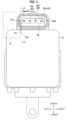
Fig. 3 is a front elevational view showing a board storage portion and a connector portion of the electrically operated valve according to the first embodiment. -
Fig. 4 is a perspective view showing the board storage portion (in a state in which a lid body is not attached) and the connector portion of the electrically operated valve according to the first embodiment. -
Fig. 5 is a perspective view showing the board storage portion (in a state in which the lid body is not attached) and the connector portion of the electrically operated valve according to the first embodiment by partly cutting off (reference sign B portion inFig. 3 ) so that a communicating passage is visible. -
Fig. 6 is a vertical cross sectional view (cross sectional view as seen from an arrow C-C inFig. 3 ) showing the communicating passage of the electrically operated valve according to the first embodiment. -
Fig. 7 is a vertical cross sectional view showing a valve close state of an electrically operated valve according to a second embodiment of the present invention. -
Fig. 8 is a vertical cross sectional view showing a valve open state of the electrically operated valve according to the second embodiment. - As shown in
Figs. 1 to 6 , an electrically operatedvalve 11 according to a first embodiment of the present invention is an electrically operated valve which is preferably used for regulating a flow rate of a refrigerant in a refrigeration cycle apparatus, for example, an air conditioning machine, and is provided with a valvemain body 12 having avalve chamber 13 in an internal portion thereof and also having aninflow passage 16 which allows the refrigerant to flow into thevalve chamber 13 and anoutflow passage 15 which allows the refrigerant to flow out of thevalve chamber 13, avalve seat 14 which is formed in an opening portion for thevalve chamber 13 in theinflow passage 16, avalve body 17 which changes a passing quantity (flow rate) of the refrigerant by moving forward and backward (moving upward and downward) with respect to thevalve seat 14 between a valve close state (refer toFig. 1 ) coming into contact with thevalve seat 14 and a valve open state (refer toFig. 2 ) being away from thevalve seat 14, anelectric motor 23 which drives thevalve body 17, acoupling member 19 which couples theelectric motor 23 to the valvemain body 12, a printed board (control board) 46 which mounts a controller (not shown) controlling theelectric motor 23 thereon, a case (board storage portion/case portion) 43 which stores theboard 46, alid body 47 which occludes a front opening of thecase 43, aconnector 44 which has an externalportion connecting terminal 45 electrically connecting to the external portion, acommunication hole 51 which communicates an internal portion of thecase 43 with an internal portion of theconnector 44, and a can (sealed container) 22 which covers anupper opening 12a of the valvemain body 12 communicating with thevalve chamber 13 and forms a sealed space together with thecoupling member 19. - Each of the drawings appropriately shows two-dimensional coordinates or three-dimensional coordinates which represent a longitudinal direction, a horizontal direction and a vertical direction and are orthogonal to each other, and the following description will be given on the basis of these directions. Further, in the present embodiment, the refrigerant is flowed into from the
inflow passage 16 and the refrigerant is flowed out of theoutflow passage 15. However, it goes without saying that the electrically operatedvalve 11 can be used in a case where a flowing direction of the refrigerant is an inverse direction. - The
electric motor 23 is constructed by a stepping motor including astator 25 which is arranged in an outer side of thecan 22, and a magnet rotor (hereinafter, refer simply to "rotor") 24 which is arranged in an inner side of the can so as to be rotatable and slidable in a vertical direction. Further, thestator 25 includes ayoke 26, abobbin 27 and acoil 28. - The
stator 25 and thecan 22 are covered by an outer shell cover (outer shell forming portion) 42 made of a synthetic resin. Further, theouter shell cover 42 is provided in an inner side thereof with a coil cover (coil coating forming portion) 41 which covers thecoil 28 and is made of a synthetic resin, and a terminal cover (terminal coating forming portion) 55 which covers and supports an intermediate portion of the externalportion connecting terminal 45. - The external
portion connecting terminal 45 has aleading end portion 45a which protrudes toward aninternal space 44a of theconnector 44 and allows an electrical connection to the external portion, and abase end portion 45b which is electrically connected to theboard 46. An intermediate portion corresponding to a portion between theleading end portion 45a and thebase end portion 45b is covered by theterminal cover 55. Further, one end portion (end portion in a connector side) of theterminal cover 55 exposes to theinternal space 44a of theconnector 44, and anopening 51a in one side (connector side) of the communicating passage 51 (refer toFigs. 3 to 6 ) is formed in the one end portion. On the contrary, the other end portion (end portion in a case side) of theterminal cover 55 exposes to theinternal space 43a of thecase 43, and anopening 51b in the other side (case side) of the communicatingpassage 51 is formed in the other end portion. The communicatingpassage 51 communicating the caseinternal portion 43a and the connectorinternal portion 44a is a through hole which has theconnector side opening 51 in one end and has thecase side opening 51b in the other end. - Further, each of the covers (
coil cover 41,terminal cover 55 and outer shell cover 42) is formed according to an injection molding. In the order of formation, first of all, thecoil cover 41 and the terminal cover 55 (fine dot patterns are respectively applied thereto inFigs. 1 and2 ) are independently formed, thecoil cover 41 and theterminal cover 55 are thereafter installed within a metal mold forming theouter shell cover 42, and the outer shell cover 42 (rough dot pattens are applied inFigs. 1 and2 ) is formed in such a manner as to cover each of thecovers outer shell cover 42, the box-shapedcase 43 storing theboard 46 and theconnector 44 are integrally formed with theouter shell cover 42. - The resin materials constructing the
coil cover 41, theterminal cover 55, the outer shell cover 42 (including thecase 43 and the connector 44) and alid body 47 mentioned later can be set by the other kind of materials. However, in order to enhance bondability between the resins, the same material is preferably used. - The
case 43 is disposed in a lateral side (front side) of thestator 25, and theconnector 44 is disposed in an upper surface portion of thecase 43. Theboard 46 is stored in theinternal portion 43a of thecase 43 through the front opening of thecase 43, and thecoil 28 is electrically connected to the externalportion connecting terminal 45 via theboard 46. This is because of enabling power feeding from an external power supply (not shown) to thecoil 28. Further, a controller including a pulse generator and a motor driving circuit is mounted to theboard 46. Further, in a case where a magnetic sensor detecting rotation of therotor 24 is provided in the electrically operatedvalve 11, a computing apparatus computing an angle of rotation of therotor 24 and an opening degree of the valve on the basis of an output signal from the magnetic sensor may be mounted to theboard 46. - The
case 43 and theconnector 44 are both constructed as a sealable structure, however, both the elements (thecase 43 and the connector 44) are communicated by the communicatingpassage 51 as mentioned above. More specifically, theinternal portion 44a of theconnector 44 comes to a sealed state by fitting a mating connector (not shown) to a front end portion of theconnector 44. The mating connector is a connector for achieving an electrical connection to the externalportion connecting terminal 45 from the external portion, and has such a shape as to fit in a sealed state to theconnector 45 of the electrically operatedvalve 11. The mating connector (accordingly theconnector 44 of the electrically operatedvalve 11 fitted thereto also) has various shapes which conform to the specification of the user of the electrically operatedvalve 11 as mentioned above. Further, the sealed state means a state in which any moisture does not infiltrate into theinternal portion 44a of theconnector 44 in a normal use state of the electrically operatedvalve 11. In the present embodiment, theinternal portion 44a of theconnector 44 is cut off from the external space (atmosphere side). - In the meantime, the
case 43 comes to a sealed state in which thecase 43 is cut off from the outside by welding theresin lid body 47 to the front opening to close the front opening, except the structure in which thecase 43 communicates with the inside 44a of theconnector 44 through the communicatingpassage 51. - Further, the electrically operated
valve 11 is provided with a rod-shaped valve stem 18 which extends in a vertical direction from an internal portion of therotor 24 toward thevalve chamber 13 along a central axis line A. The valve stem 18 has a columnar barrel portion 18a, and an upper small-diameter portion 18b which is coaxially formed in an upper end portion of the barrel portion 18a in succession to the barrel portion 18a and has a small outer diameter. Further, thevalve body 17 is integrally provided in a lower end of the valve stem 18 (barrel portion 18a). Therotor 24 is arranged in an inner side of thecan 22 so as to be rotatable and slidable in the vertical direction, and the valve is opened and closed by the integral movement in the vertical direction of the valve stem 18 provided with thevalve body 17 in the lower end and therotor 24. - A
valve stem holder 31 is provided in an inner side of therotor 24. Thevalve stem holder 31 has a cylindrical shape which is closed in an upper end, and asupport ring 33 is fixed to an upper end portion of thevalve stem holder 31 by a caulking. Further, therotor 24 and thevalve stem holder 31 are integrally connected via thesupport ring 33. Afemale screw portion 31a is formed on an inner peripheral surface of thevalve stem holder 31. Thefemale screw portion 31a constructs a transfer mechanism (screw feeding mechanism) which is threadably mounted on amale screw portion 36a of aguide bush 36 mentioned later and converts the rotation of theelectric motor 23 into a linear motion to transfer to the valve stem 18. - The upper small-
diameter portion 18b of the valve stem 18 passes through thevalve stem holder 31, and apush nut 34 for retaining is attached to an upper end portion of the upper small-diameter portion 18b. The valve stem 18 is biased downward by acompression coil spring 35 which is disposed between thevalve stem holder 31, and a step portion between the barrel portion 18a and the upper small-diameter portion 18b in the valve stem 18. Therefore, the valve stem 18 is regulated its relative movement in the vertical direction to thevalve stem holder 31 by thepush nut 34 and thecompression coil spring 35, and moves upward and downward together with the valve stem holder 18. - The
coupling member 19 is a tubular member having a large-diameter hole 19a and a small-diameter hole 19b which are through holes communicating with each other. The large-diameter hole 19a passes through an upper center portion of thecoupling member 19, and has a large diameter so that theguide bush 36 mentioned later can be fitted and inserted from the above. The small-diameter hole 19b passes through a lower center portion of thecoupling member 19 and has a small diameter. Further, the cylindrical can 22 which is covered and not bottomed (in which a bottom surface is opened and a top surface is occluded) is joined to an outer peripheral surface of the upper end portion of thecoupling member 19 via a ring-shapedbase plate 21. - The
guide bush 36 is fixed to the large-diameter hole 19a in the upper portion of thecoupling member 19. Theguide bush 36 has a large-diametercylindrical portion 36a which has a large outer diameter, and a small-diametercylindrical portion 36b which is coaxially formed in an upper end portion of the large-diametercylindrical portion 36a in succession to the large-diametercylindrical portion 36a and has a small outer diameter. Amale screw portion 36c threadably mounted on thefemale screw portion 31a of thevalve stem holder 31 is formed on an outer peripheral surface of the small-diametercylindrical portion 36b. Theguide bush 36 is connected to thecoupling member 19 by pressing the large-diametercylindrical portion 36a in an inner side of thecoupling member 19. Further, the barrel portion 18a of the valve stem 18 passes through the small-diameter hole 19b of thecoupling member 19. - Further, an
upper stopper body 32 is disposed in thevalve stem holder 31, and alower stopper body 37 is disposed in the large-diametercylindrical portion 36a of theguide bush 36. Thestopper bodies valve stem holder 31, and when thevalve stem holder 31 moves down by rotating to reach the lower limit position, theupper stopper body 32 comes into contact with thelower stopper body 37 and further rotation of thevalve stem holder 31 is regulated. - The mechanism for transferring the drive force of the
electric motor 23 to thevalve body 17 can employ various mechanisms in addition to the above mechanism, and is not limited to the above structure. - A description will be given below of a motion of the electrically operated valve according to the present embodiment.
- When an electric current is supplied to the stator 25 (coil 28) in such a manner that the
rotor 24 turns in one direction from the valve close state shown inFig. 1 , thevalve stem holder 31 connected to therotor 24 turns together with therotor 24. Since thefemale screw portion 31a threadably mounted on themale screw portion 36c formed on the outer peripheral surface of the small-diametercylindrical portion 36b of theguide bush 36 is formed on the inner peripheral surface of thevalve stem holder 31, the rotation of the rotor 24 (valve stem holder 31) is converted into the liner motion in the vertical direction on the basis of an interaction of themale screw portion 36c and thefemale screw portion 31a, and thevalve stem holder 31 moves upward. As a result, therotor 24 connected to thevalve stem holder 31, and the valve stem 18 regulating its relative movement to thevalve stem holder 31 also move upward together with thevalve stem holder 31. Thevalve body 17 disposed in the lower end of the valve stem 18 is away from thevalve seat 14 accompanied with the upward movement of the valve stem 18, so that the refrigerant flowing into from theinflow passage 16 is going to flow out of theoutflow passage 15 through the valve chamber 13 (refer toFig. 2 ). A passing quantity (refrigerant flow rate) of the refrigerant can be adjusted on the basis of an amount of rotation of therotor 24. - On the contrary, when the electric current is supplied to the stator 25 (coil 28) in such a manner that the
rotor 24 turns in a direction opposite to the one direction from the valve open state, the rotation of the rotor 24 (valve stem holder 31) is converted into the linear motion in the vertical direction on the basis of the interaction of thefemale screw portion 31a and themale screw portion 36c. As a result, thevalve stem holder 31 moves downward together with therotor 24 and the valve stem 18. Thus, thevalve body 17 moves downward toward thevalve seat 14, and a flow passage between theinflow passage 16 and theoutflow passage 15 is cut off when thevalve body 17 comes into contact with thevalve seat 14, thereby coming to the valve close state (refer toFig. 1 ). - In the electrically operated
valve 11 according to the present embodiment, the communicatingpassage 51 is disposed between theconnector 44 and thecase 43. Therefore, the airtightness inspection of thecase 43 can be performed in a completed state in which theboard 46 is stored in thecase 43 and thelid body 47 closing the front opening is welded to thecase 43. The inspection can be performed, for example, by pressing the gas (air or inert gas) in the caseinternal portion 43a at a fixed pressure from theconnector 44 via the communicatingpassage 51 so as to set the caseinternal portion 43a in a highpressure state, and monitoring a change in the gas pressure. The reduction of the gas pressure means leakage of the gas. Thus, existence of poor sealing can be found. On the contrary, if the gas pressure is kept constant, it is possible to find that the product is a normal product having no poor sealing. - A description will be given of an electrically operated valve according to a second embodiment of the present invention with reference to
Figs. 7 to 8 . In the following description, same reference numerals are attached to the same structures as those of the electrically operatedvalve 11 according to the first embodiment, a redundant description will be omitted, and the description will be given mainly of different points. - As shown in
Figs. 7 to 8 , an electrically operatedvalve 61 according to the present embodiment is adapted to move thevalve body 17 upward and downward by the electric motor (stepping motor) 23 to regulate the flow rate of the refrigerant in the same manner as the electrically operatedvalve 11 according to the first embodiment, and is provided with theboard 46 which controls theelectric motor 23. However, theboard 46 is arranged in the upper surface portion of the electric motor 23 (stator 25) so as to horizontally extend, and thecase 43 storing theboard 46 is formed in the upper surface portion of theelectric motor 23. - The present embodiment is provided with the outer shell cover 42 (to which a rough dot pattern is applied in
Figs. 7 and8 ) which covers thestator 25 of theelectric motor 23 and thecan 22, and the coil cover 41 (to which a fine dot pattern is applied inFigs. 7 and8 ) which is arranged in the inner side of theouter shell cover 42 and covers thecoil 28 in the same manner as the electrically operatedvalve 11 according to the first embodiment. However, as is different from the electrically operatedvalve 11 according to the first embodiment, theconnector 44 is not integrally formed with theouter shell cover 42, but is formed as alid body 62 with connector in a different step and is integrally formed with thelid body 47 which occludes the upper opening of thecase 43. - The
lid body 62 with connector is manufactured via two stages of forming steps. First of all, a first step forms the terminal cover (terminal coating molded portion) 55 which covers and supports the intermediate portion of the externalportion connecting terminal 45 and is made of resin, and a successive second step integrally forms theconnector 44 and thelid body 47 as thelid body 62 with connector in such a manner that theterminal cover 55 covers theterminal cover 55 and is supported between theconnector 44 and thelid body 47, in other words, such that theterminal cover 55 passes through a boundary portion between theconnector 44 and thelid body 47, further in other words, such that one end portion of theterminal cover 55 protrudes to the connectorinternal portion 44a and the other end portion of theterminal cover 55 protrudes downward from the lower surface of thelid body 47. - Further, in the present embodiment, the communicating
passage 51 is formed in theterminal cover 55 in the first step of forming theterminal cover 55. The communicatingpassage 51 is a through hole which communicates the connectorinternal portion 44a with the caseinternal portion 43a in the same manner as the first embodiment, has theconnector side opening 51a in one end portion of theterminal cover 55, and has thecase side opening 51b in the other end portion. - In the second step mentioned above, the
connector side opening 51a is positioned within theinternal space 44a of theconnector 44 due to the protrusion of the end portion in the connector side of theterminal cover 55 into theinternal space 44a of theconnector 44, and thecase side opening 51b is positioned below the lower surface of thelid body 47 due to the protrusion of the end portion in the lid body side from the lower surface of thelid body 47. Therefore, it is possible to prevent the communicating passage 51 (connector side opening 51a andcase side opening 51b) from being closed due to the infiltration of the resin forming theouter shell cover 42 when forming the outer shell cover 42 (in the second step) into the communicatingpassage 51 from theconnector side opening 51a and thecase side opening 51b. - The
lid body 62 with connector is welded to the upper edge portion of thecase 43 in such a manner as to occlude the upper opening of thecase 43 after installing theboard 46 in the caseinternal portion 43a. The electrical connection between the externalportion connecting terminal 45 and theboard 46 may be achieved by a press fit connection. More specifically, with the use of the base end portion (end portion in the board side) 45b of the eternalportion connecting terminal 45 ad a press fit pin, the press fit pin is adapted to be pressed in a through hole of theboard 46 when putting thelid body 62 with connector on the upper surface of thecase 43. - In the present embodiment, the case
internal portion 43a and the connectorinternal portion 44a come to a communicated state by the communicatinghole 51 which passes through theterminal cover 55. Therefore, in the same manner as the first embodiment, it is possible to fine the poor sealing by pressing the gas for inspection in the caseinternal portion 43a from theconnector 44 via the communicatingpassage 51 and monitoring the pressure change. -
- A central axis line
- 11, 61 electrically operated valve
- 12 valve main body
- 12a upper opening
- 13 valve chamber
- 14 valve seat
- 15 outflow passage
- 16 inflow passage
- 17 valve body
- 18 valve stem
- 18a barrel portion
- 18b upper small-diameter portion
- 19 coupling member
- 19a large-diameter hole
- 19b small-diameter hole
- 21 base plate
- 22 can
- 23 stepping motor (electric motor)
- 24 magnet rotor
- 25 stator
- 26 yoke
- 27 bobbin
- 28 coil
- 31 valve stem holder
- 31a female screw portion (screw feeding mechanism)
- 32 upper stopper body
- 33 support ring
- 34 push nut
- 35 compression coil spring
- 36 guide bush
- 36a large-diameter cylindrical portion
- 36b small-diameter cylindrical portion
- 36c male screw portion (screw feeding mechanism)
- 37 lower stopper body
- 41 coil cover
- 42 outer shell cover
- 43 case
- 43a case internal portion (internal space of case)
- 44 connector
- 44a connector internal portion (internal space of connector)
- 45 external portion connecting terminal
- 45a leading end portion of external portion connecting terminal (end portion in connector side)
- 45b base end portion of external portion connecting terminal (end portion in board side)
- 46 board
- 47 lid body
- 51 communicating passage
- 51a connector side opening
- 51b case side opening
- 55 terminal cover
- 62 lid body with connector
Claims (10)
- An electrically operated valve comprising:a valve main body having a valve chamber which is communicated with an inflow passage introducing a refrigerant and an outflow passage discharging the refrigerant;a valve body which changes a flow rate of the refrigerant by moving forward and backward with respect to a valve seat formed within the valve chamber between a valve close state seating on the valve seat and a valve open state separating from the valve seat;an electric motor which drives the valve body;a control board on which an electronic component controlling the electric motor is mounted;a board storage portion which allows the control board to be stored in a sealed state; anda connector portion having an external portion connecting terminal which performs an electrical connection to the external portion and a sealing structure which is sealed by fitting to a mating connector,wherein the electrically operated valve further comprises a communicating passage which allows the board storage portion and the connector portion to be communicated, andwherein the board storage portion comes to the sealed state when the mating connector is fitted to the connector portion.
- The electrically operated valve according to claim 1, wherein the board storage portion includes:a case portion having an opening which allows the control board to be stored in an internal portion thereof and allows the board to be installed in the internal portion thereof; anda lid body which occludes the opening.
- The electrically operated valve according to claim 2, further comprising an outer shell forming portion which covers a stator of the electric motor,
wherein the outer shell forming portion and the case portion are integrally formed. - The electrically operated valve according to claim 3, wherein a coil coating forming portion covering a coil included in the stator is disposed in an inner side of the outer shell forming portion.
- The electrically operated valve according to claim 3 or 4, wherein the outer shell forming portion, the case portion and the connector portion are integrally formed.
- The electrically operated valve according to any one of claims 2 to 5, wherein the electrically operated valve further comprises a terminal coating forming portion which is formed in an inner side of the connector portion, and covers and supports an intermediate portion of an external portion connecting terminal, and
wherein the communicating passage is formed in the terminal coating forming portion. - The electrically operated valve according to claim 6, wherein one end portion of the terminal coating forming portion exposes to an internal space of the connector portion, and one opening of the communicating passage is formed in the one end portion, and
wherein the other end portion of the terminal coating forming portion exposes to an internal space of the case portion and the other opening of the communicating passage is formed in the other end portion. - The electrically operated valve according to any one of claims 2 to 4, wherein the connector and the lid body are integrally formed as a lid body with connector portion,wherein the electrically operated valve further comprises a terminal coating forming portion which is formed in an inner side of the lid body with connector portion, and covers and supports an intermediate portion of an external portion connecting terminal, andwherein the communicating passage is formed in the terminal coating forming portion.
- The electrically operated valve according to claim 8, wherein one end portion of the terminal coating forming portion exposes to an internal space of the connector portion, and one opening of the communicating passage is formed in the one end portion, and
wherein the other end portion of the terminal coating forming portion exposes to a lower surface of the lid body in such a manner as to expose to an internal space of the case portion, and the other opening of the communicating passage is formed in the other end portion. - A stator which can be disposed in an electric motor driving a valve body of an electrically operated valve,
wherein the stator includes:a control board on which an electronic component controlling the electric motor is mounted;a board storage portion which allows the control board to be stored in a sealed state;a connector portion having an external portion connecting terminal which performs an electrical connection to the external portion and having a sealing structure which is sealed by fitting to a mating connector; anda communicating passage which allows the board storage portion and the connector portion to be communicated, andwherein the board storage portion comes to the sealed state when the mating connector is fitted to the connector portion.
Applications Claiming Priority (2)
| Application Number | Priority Date | Filing Date | Title |
|---|---|---|---|
| JP2021183277 | 2021-11-10 | ||
| PCT/JP2022/033519 WO2023084892A1 (en) | 2021-11-10 | 2022-09-07 | Electric valve |
Publications (2)
| Publication Number | Publication Date |
|---|---|
| EP4431773A1 true EP4431773A1 (en) | 2024-09-18 |
| EP4431773A4 EP4431773A4 (en) | 2025-11-12 |
Family
ID=86335486
Family Applications (1)
| Application Number | Title | Priority Date | Filing Date |
|---|---|---|---|
| EP22884773.7A Pending EP4431773A4 (en) | 2021-11-10 | 2022-09-07 | ELECTRIC VALVE |
Country Status (6)
| Country | Link |
|---|---|
| US (2) | US12169031B2 (en) |
| EP (1) | EP4431773A4 (en) |
| JP (2) | JP7438590B2 (en) |
| KR (1) | KR20230070470A (en) |
| CN (1) | CN118140082A (en) |
| WO (1) | WO2023084892A1 (en) |
Families Citing this family (1)
| Publication number | Priority date | Publication date | Assignee | Title |
|---|---|---|---|---|
| US12258746B2 (en) * | 2022-12-05 | 2025-03-25 | B/E Aerospace, Inc. | Electro pneumatic and electromechanical actuated diaphragm type flush valve for aircraft toilet |
Family Cites Families (17)
| Publication number | Priority date | Publication date | Assignee | Title |
|---|---|---|---|---|
| JPH10103555A (en) * | 1996-09-24 | 1998-04-21 | Ckd Corp | Power supply device for pilot solenoid valve |
| JP2002070743A (en) * | 2000-08-29 | 2002-03-08 | Sanden Corp | Motor-driven compressor for refrigerant compression |
| JP4303162B2 (en) * | 2004-05-25 | 2009-07-29 | ミネベア株式会社 | Actuator |
| JP2008190566A (en) * | 2007-02-01 | 2008-08-21 | Advics:Kk | Hydraulic control device and its assembling method |
| WO2009009640A1 (en) * | 2007-07-10 | 2009-01-15 | Continental Automotive Systems Us, Inc. | Idle air control valve |
| JP5435902B2 (en) * | 2008-07-07 | 2014-03-05 | サーパス工業株式会社 | Flow control valve |
| JP2010267589A (en) * | 2009-05-18 | 2010-11-25 | Sumitomo Wiring Syst Ltd | Connector device |
| JP5477257B2 (en) * | 2010-10-29 | 2014-04-23 | 住友電装株式会社 | Connector for equipment |
| JP5840552B2 (en) * | 2012-03-30 | 2016-01-06 | 株式会社ミツバ | Electric motor |
| JP6083294B2 (en) | 2013-03-28 | 2017-02-22 | 株式会社豊田自動織機 | Electric compressor and manufacturing method thereof |
| DE102014106513A1 (en) | 2014-05-09 | 2015-11-12 | Pierburg Gmbh | Exhaust gas turbocharger with a wastegate valve |
| JP6518713B2 (en) * | 2017-04-12 | 2019-05-22 | 株式会社不二工機 | Motorized valve |
| EP3734313B1 (en) * | 2019-04-30 | 2021-12-01 | ASOCIACIÓN CENTRO DE INVESTIGACIÓN COOPERATIVA EN NANOCIENCIAS "CIC nanoGUNE" | Method for extracting a transverse magneto-optic effect signal |
| JP7462282B2 (en) | 2019-08-22 | 2024-04-05 | 株式会社テージーケー | Motor-operated valve |
| JP7168232B2 (en) | 2020-01-14 | 2022-11-09 | 株式会社不二工機 | electric valve |
| JP2021113594A (en) * | 2020-01-20 | 2021-08-05 | いすゞ自動車株式会社 | Valve device |
| JP7592323B2 (en) * | 2022-08-23 | 2024-12-02 | 株式会社不二工機 | Stator unit, motorized valve and motorized valve device |
-
2022
- 2022-09-07 CN CN202280007671.3A patent/CN118140082A/en active Pending
- 2022-09-07 KR KR1020237012820A patent/KR20230070470A/en active Pending
- 2022-09-07 JP JP2023503414A patent/JP7438590B2/en active Active
- 2022-09-07 WO PCT/JP2022/033519 patent/WO2023084892A1/en not_active Ceased
- 2022-09-07 US US18/250,788 patent/US12169031B2/en active Active
- 2022-09-07 EP EP22884773.7A patent/EP4431773A4/en active Pending
-
2024
- 2024-02-06 JP JP2024016068A patent/JP7720648B2/en active Active
- 2024-10-24 US US18/925,908 patent/US20250052335A1/en active Pending
Also Published As
| Publication number | Publication date |
|---|---|
| WO2023084892A1 (en) | 2023-05-19 |
| CN118140082A (en) | 2024-06-04 |
| JP2024046669A (en) | 2024-04-03 |
| US12169031B2 (en) | 2024-12-17 |
| KR20230070470A (en) | 2023-05-23 |
| US20250052335A1 (en) | 2025-02-13 |
| JPWO2023084892A1 (en) | 2023-05-19 |
| EP4431773A4 (en) | 2025-11-12 |
| US20240318739A1 (en) | 2024-09-26 |
| JP7438590B2 (en) | 2024-02-27 |
| JP7720648B2 (en) | 2025-08-08 |
Similar Documents
| Publication | Publication Date | Title |
|---|---|---|
| US20250052335A1 (en) | Electrically operated valve | |
| EP3315835B1 (en) | Electric valve and assembly method thereof | |
| US20040135658A1 (en) | Solenoid arrangement | |
| CN102543582A (en) | Method for manufacturing sealed contactor | |
| CN101324290A (en) | Electro-pneumatic cartridge valve and method for simplified manufacture of the same | |
| US20250283550A1 (en) | Electrically operated valve | |
| JP2018179205A (en) | Control valve and manufacturing method of the same | |
| JP4733041B2 (en) | Solenoid control valve | |
| JP2025188265A (en) | Stator unit, motor-operated valve, and motor-operated valve device | |
| EP4224681A1 (en) | Stator unit and electric valve | |
| US20220375707A1 (en) | Electromagnetic relay | |
| CN101153672B (en) | Coil locating structure of electronic expansion valve | |
| JP2017033952A (en) | relay | |
| JPH11132352A (en) | solenoid valve | |
| CN220668533U (en) | Electronic expansion valve for vehicle | |
| CN223390454U (en) | Relay device | |
| CN220980454U (en) | Coil component and electronic expansion valve | |
| JP2005280444A (en) | Brake hydraulic pressure control device for vehicles | |
| JP7021425B2 (en) | Electrical resistance welding electrode and its cooling method | |
| EP4421367A1 (en) | Electric valve | |
| CN223447787U (en) | Electrically actuated valve | |
| CN213982634U (en) | Sealed thermoregulator seat | |
| CN121953086A (en) | Valve device | |
| CN110375104A (en) | Motor-driven valve | |
| CN201475474U (en) | High-voltage solenoid valve |
Legal Events
| Date | Code | Title | Description |
|---|---|---|---|
| STAA | Information on the status of an ep patent application or granted ep patent |
Free format text: STATUS: UNKNOWN |
|
| STAA | Information on the status of an ep patent application or granted ep patent |
Free format text: STATUS: THE INTERNATIONAL PUBLICATION HAS BEEN MADE |
|
| PUAI | Public reference made under article 153(3) epc to a published international application that has entered the european phase |
Free format text: ORIGINAL CODE: 0009012 |
|
| STAA | Information on the status of an ep patent application or granted ep patent |
Free format text: STATUS: REQUEST FOR EXAMINATION WAS MADE |
|
| 17P | Request for examination filed |
Effective date: 20230505 |
|
| AK | Designated contracting states |
Kind code of ref document: A1 Designated state(s): AL AT BE BG CH CY CZ DE DK EE ES FI FR GB GR HR HU IE IS IT LI LT LU LV MC MK MT NL NO PL PT RO RS SE SI SK SM TR |
|
| DAV | Request for validation of the european patent (deleted) | ||
| DAX | Request for extension of the european patent (deleted) | ||
| REG | Reference to a national code |
Ref country code: DE Ref legal event code: R079 Free format text: PREVIOUS MAIN CLASS: F16K0031040000 Ipc: H02K0005100000 |
|
| A4 | Supplementary search report drawn up and despatched |
Effective date: 20251013 |
|
| RIC1 | Information provided on ipc code assigned before grant |
Ipc: H02K 5/10 20060101AFI20251007BHEP Ipc: H02K 5/22 20060101ALI20251007BHEP Ipc: F16K 31/04 20060101ALI20251007BHEP Ipc: H02K 11/30 20160101ALI20251007BHEP Ipc: F25B 41/20 20210101ALI20251007BHEP Ipc: F25B 41/35 20210101ALI20251007BHEP Ipc: G01M 3/28 20060101ALI20251007BHEP Ipc: H02K 15/14 20060101ALI20251007BHEP Ipc: H02K 37/14 20060101ALN20251007BHEP Ipc: H02K 5/08 20060101ALN20251007BHEP Ipc: H02K 7/14 20060101ALN20251007BHEP |