EP4431431A1 - A tension element for use in a load bearing member of an elevator system - Google Patents
A tension element for use in a load bearing member of an elevator system Download PDFInfo
- Publication number
- EP4431431A1 EP4431431A1 EP24160013.9A EP24160013A EP4431431A1 EP 4431431 A1 EP4431431 A1 EP 4431431A1 EP 24160013 A EP24160013 A EP 24160013A EP 4431431 A1 EP4431431 A1 EP 4431431A1
- Authority
- EP
- European Patent Office
- Prior art keywords
- layer
- wires
- tension element
- diameter
- load bearing
- Prior art date
- Legal status (The legal status is an assumption and is not a legal conclusion. Google has not performed a legal analysis and makes no representation as to the accuracy of the status listed.)
- Pending
Links
Images



Classifications
-
- B—PERFORMING OPERATIONS; TRANSPORTING
- B66—HOISTING; LIFTING; HAULING
- B66B—ELEVATORS; ESCALATORS OR MOVING WALKWAYS
- B66B7/00—Other common features of elevators
- B66B7/06—Arrangements of ropes or cables
- B66B7/062—Belts
-
- B—PERFORMING OPERATIONS; TRANSPORTING
- B66—HOISTING; LIFTING; HAULING
- B66B—ELEVATORS; ESCALATORS OR MOVING WALKWAYS
- B66B7/00—Other common features of elevators
- B66B7/06—Arrangements of ropes or cables
-
- B—PERFORMING OPERATIONS; TRANSPORTING
- B66—HOISTING; LIFTING; HAULING
- B66B—ELEVATORS; ESCALATORS OR MOVING WALKWAYS
- B66B5/00—Applications of checking, fault-correcting, or safety devices in elevators
- B66B5/0006—Monitoring devices or performance analysers
- B66B5/0018—Devices monitoring the operating condition of the elevator system
- B66B5/0031—Devices monitoring the operating condition of the elevator system for safety reasons
-
- D—TEXTILES; PAPER
- D07—ROPES; CABLES OTHER THAN ELECTRIC
- D07B—ROPES OR CABLES IN GENERAL
- D07B1/00—Constructional features of ropes or cables
- D07B1/06—Ropes or cables built-up from metal wires, e.g. of section wires around a hemp core
-
- D—TEXTILES; PAPER
- D07—ROPES; CABLES OTHER THAN ELECTRIC
- D07B—ROPES OR CABLES IN GENERAL
- D07B1/00—Constructional features of ropes or cables
- D07B1/14—Ropes or cables with incorporated auxiliary elements, e.g. for marking, extending throughout the length of the rope or cable
- D07B1/145—Ropes or cables with incorporated auxiliary elements, e.g. for marking, extending throughout the length of the rope or cable comprising elements for indicating or detecting the rope or cable status
-
- D—TEXTILES; PAPER
- D07—ROPES; CABLES OTHER THAN ELECTRIC
- D07B—ROPES OR CABLES IN GENERAL
- D07B1/00—Constructional features of ropes or cables
- D07B1/16—Ropes or cables with an enveloping sheathing or inlays of rubber or plastics
-
- B—PERFORMING OPERATIONS; TRANSPORTING
- B66—HOISTING; LIFTING; HAULING
- B66B—ELEVATORS; ESCALATORS OR MOVING WALKWAYS
- B66B7/00—Other common features of elevators
- B66B7/12—Checking, lubricating, or cleaning means for ropes, cables or guides
- B66B7/1207—Checking means
- B66B7/1215—Checking means specially adapted for ropes or cables
- B66B7/1223—Checking means specially adapted for ropes or cables by analysing electric variables
-
- D—TEXTILES; PAPER
- D07—ROPES; CABLES OTHER THAN ELECTRIC
- D07B—ROPES OR CABLES IN GENERAL
- D07B1/00—Constructional features of ropes or cables
- D07B1/16—Ropes or cables with an enveloping sheathing or inlays of rubber or plastics
- D07B1/162—Ropes or cables with an enveloping sheathing or inlays of rubber or plastics characterised by a plastic or rubber enveloping sheathing
-
- D—TEXTILES; PAPER
- D07—ROPES; CABLES OTHER THAN ELECTRIC
- D07B—ROPES OR CABLES IN GENERAL
- D07B1/00—Constructional features of ropes or cables
- D07B1/22—Flat or flat-sided ropes; Sets of ropes consisting of a series of parallel ropes
-
- D—TEXTILES; PAPER
- D07—ROPES; CABLES OTHER THAN ELECTRIC
- D07B—ROPES OR CABLES IN GENERAL
- D07B2201/00—Ropes or cables
- D07B2201/10—Rope or cable structures
- D07B2201/1012—Rope or cable structures characterised by their internal structure
-
- D—TEXTILES; PAPER
- D07—ROPES; CABLES OTHER THAN ELECTRIC
- D07B—ROPES OR CABLES IN GENERAL
- D07B2201/00—Ropes or cables
- D07B2201/20—Rope or cable components
- D07B2201/2083—Jackets or coverings
- D07B2201/2087—Jackets or coverings being of the coated type
Definitions
- Exemplary embodiments disclosed herein relate to elevator systems, and more particularly, to a load bearing member such as used in elevator systems for suspension and/or driving of the elevator car and/or counterweight.
- Elevator systems are useful for carrying passengers, cargo, or both, between various levels in a building.
- Some elevators are traction based and utilize load bearing members such as ropes or belts for supporting the elevator car and achieving the desired movement and positioning of the elevator car.
- each individual rope is not only a traction device for transmitting the pulling forces but also participates directly in the transmission of the traction forces.
- belts are used as a load bearing member, a plurality of tension elements are embedded in an elastomer belt body. The tension elements are exclusively responsible for transmitting the pulling forces, while the elastomer material transmits the traction forces. Due to the forces acting thereon, each of these tension elements is typically formed from a plurality of fine steel elements or wires.
- Deterioration of load bearing members can be caused by normal operation of the elevator over time.
- the primary source of deterioration is the cyclic bending of the load bearing members around sheaves as the elevator is moved up and down in a hoistway.
- the condition of the load bearing members is critical to the safety of the operation of the elevator, it is desirable to monitor a condition of the load bearing member to detect deterioration, e.g., corrosion, fretting, wire breakage, etc., of the tension elements.
- a tension element for use in a load bearing member of an elevator system includes a first layer having a plurality of first wires and a second layer having a plurality of second wires.
- the second layer is positioned radially outward of and surrounds the first layer.
- the first layer has a first lay direction and the second layer has a second lay direction.
- the second lay direction is opposite the first lay direction.
- Particular embodiments may include at least one, or a plurality of, the following optional features, alone or in combination with each other:
- the first lay direction is counterclockwise and the second lay direction is clockwise.
- first lay direction is clockwise and the second lay direction is counterclockwise.
- the plurality of second wires is greater than the plurality of first wires.
- the plurality of second wires is less than the plurality of first wires.
- the plurality of first wires have a first diameter and the plurality of second wires have a second diameter.
- the second diameter is different than the first diameter.
- the second diameter is larger than the first diameter.
- the third layer has the first lay direction.
- the third layer has the second lay direction.
- the third layer further includes a plurality of third wires having a third diameter and a plurality of fourth wires having a fourth diameter.
- the fourth diameter is larger than the third diameter.
- a load bearing system for use in an elevator system includes a load bearing member.
- the load bearing member includes at least one tension element having a plurality of wires arranged in a first layer and a second layer.
- the second layer is positioned radially outward of and directly adjacent to the first layer such that the second layer surrounds the first layer.
- the first layer has a first lay direction and the second layer has a second lay direction.
- the second lay direction is opposite the first lay direction.
- a jacket material encapsulates the at least one tension element.
- Particular embodiments may include at least one, or a plurality of, the following optional features, alone or in combination with each other:
- the first lay direction is counterclockwise and the second lay direction is clockwise.
- first lay direction is clockwise and the second lay direction is counterclockwise.
- the load bearing member further includes a coating layer encapsulating the first layer.
- an inspection device operably coupled to the at least one tension element and operable to monitor an electrical resistance of the at least one tension element.
- the at least one tension element includes a plurality of tension elements spaced laterally across a width of the load bearing member.
- the inspection device is operably coupled to each of the plurality of tension elements.
- the plurality of wires being arranged in a third layer positioned radially outward of and surrounding the second layer.
- the third layer has the first lay direction.
- the third layer has the second lay direction.
- the elevator system 10 includes an elevator car 14 configured to move vertically upwardly and downwardly within a hoistway 12 along a plurality of car guide rails (not shown).
- Guide assemblies mounted to the top and bottom of the elevator car 14 are configured to engage the car guide rails to maintain proper alignment of the elevator car 14 as it moves within the hoistway 12.
- the elevator system 10 also includes a counterweight 15 configured to move vertically upwardly and downwardly within the hoistway 12.
- the counterweight 15 moves in a direction generally opposite the movement of the elevator car 14 as is known in conventional elevator systems. Movement of the counterweight 15 is guided by counterweight guide rails (not shown) mounted within the hoistway 12.
- at least one load bearing member 30, for example, a belt is coupled to both the elevator car 14 and the counterweight 15 and cooperates with a traction sheave 18 mounted to a drive machine 20. To cooperate with the traction sheave 18, at least one load bearing member 30 bends in a first direction about the traction sheave 18.
- the drive machine 20 of the elevator system 10 is positioned and supported at a mounting location atop a support member 22, such as a bedplate for example, in a portion of the hoistway 12 or a machine room.
- a support member 22 such as a bedplate for example
- the drive machine 20 of the elevator system 10 is positioned and supported at a mounting location atop a support member 22, such as a bedplate for example, in a portion of the hoistway 12 or a machine room.
- a support member 22 such as a bedplate for example
- the belt includes at least one tension element, and in some embodiments, a plurality of tension elements 32 extending longitudinally along a length of the belt 30.
- the plurality of tension elements 32 may be substantially identical, or alternatively may have different configurations. Further, the tension elements 32 be spaced apart or separated from one another such that adjacent tension elements 32 are not arranged in contact. In the illustrated, non-limiting embodiment, the plurality of tension elements 32 are spaced uniformly or non-uniformly across a lateral width of the load bearing member 30.
- the one or more tension elements 32 are at least partially enclosed in a jacket material 34 to not only to protect the tension elements 32, but also to restrain relative movement thereof.
- the jacket material 34 may define a traction surface configured to contact a corresponding surface of the traction sheave 18.
- jacket material 34 examples include, but are not limited to polyurethane, styrene butadiene rubber (SBR), nitrile rubber (NBR), acrylonitrile butadiene styrene (ABS), SBS/SEBS plastics, silicone, EPDM rubber, other curable diene based rubber, neoprene, non-curing thermoplastic elastomers, curable extrudable rubber materials, thermoplastics such as nylon, polyester, polyvinyl chloride, polyolefin or the like, each of which can be in the form of a solution, emulsion, prepolymer or other fluid phase.
- SBR styrene butadiene rubber
- NBR nitrile rubber
- ABS acrylonitrile butadiene styrene
- SBS/SEBS plastics silicone, EPDM rubber, other curable diene based rubber, neoprene, non-curing thermoplastic elastomers, curable ex
- a primary function of the jacket material 34 is to provide a sufficient coefficient of friction between the load bearing member 30 and the traction sheave 18 to produce a desired amount of traction therebetween.
- the jacket material 34 should also transmit the traction loads to the tension elements 32.
- the jacket material 34 should be wear resistant and protect the tension elements from impact damage, exposure to environmental factors, such as chemicals, for example.
- One or more additive materials may be incorporated into the jacket material 34 to enhance performance, such as traction and environmental resistance.
- carbon black is very effective in improving UV-resistance of elastomers and carbodiimides are very effective in improving hydrolysis resistance of polyurethanes.
- the belt or load bearing member 30 includes nine tension elements 32.
- the number of tension elements 32 illustrated is intended as an example only, and that a load bearing member 30 having any suitable number of tension elements, such as a single tension element, two, three, four, five, six, seven, eight, ten or more tension elements 32 is within the scope of the disclosure.
- the tension elements 32 are shown as having a substantially circular cross-section, the depiction is merely an example.
- Tension elements 32 having another cross-sectional shape, such as an elliptical or oval cross-section for example, are contemplated herein.
- each tension element 32 is formed from a plurality of wires. Although each of the wires of the tension element 32 is illustrated and described herein as a singular wire or filament, it should be appreciated that in other embodiments, each wire may in fact be a bundle or plurality of wires, such as having a twisted configuration.
- the wires of the tension element 32 may be arranged in a plurality of stacked or concentric layers including at least a first layer or core 40 and a second layer 42 located radially outward of the first layer 40.
- the first layer 40 includes a plurality of substantially identical first wires 44.
- a first diameter of the plurality of first wires 44 may vary.
- the plurality of first wires may include two or more wires having at least two different diameters.
- the plurality of first wires includes wires having three different diameters.
- the first layer 40 is illustrated as having three first wires 44, it should be understood that embodiments where the first layer 40 has any number of first wires 44, including a single wire, two wires, or more than three wires, is within the scope of the disclosure.
- the plurality of first wires 44 are bare or are not coated with or encapsulated within any material.
- a coating layer 46 may be applied about the exterior of the first layer 40 to encapsulate the plurality of first wires 44.
- Examples of the material of the coating layer 46 include, but are not limited to polyurethane, styrene butadiene rubber (SBR), nitrile rubber (NBR), acrylonitrile butadiene styrene (ABS), SBS/SEBS plastics, silicone, EPDM rubber, other curable diene-based rubber, neoprene, non-curing thermoplastic elastomers, curable extrudable rubber materials, thermoplastics such as nylon, polyester, polyvinyl chloride, polyolefin, or the like.
- the material used to form the coating layer 46 may be substantially identical to the jacket material 34, or alternatively, may be different therefrom.
- the second layer 42 similarly includes a plurality of second wires 48.
- the second wires 48 are arranged to surround or enclose the first layer 40.
- the second layer 42 typically includes a greater number of wires than the first layer 40, as shown in FIGS. 3 and 4 .
- the second layer 42 includes nine second wires 48.
- the plurality of second wires 48 may be substantially identical to one another and have a second diameter.
- the second diameter may be equal to or may be different than the first diameter of the first wires 44.
- the second diameter is larger than the first diameter; however, in other embodiments the second diameter of the second wires 48 may be the smaller than the first diameter of the first wires 44.
- the tension element 32 may include one or more additional layers, such as a third layer 50 for example, located radially outward of and directly adjacent to the second layer 42 and having a plurality of wires configured to surround the adjacent layer 42.
- the third layer 50 typically includes more wires than the second layer 42.
- the third layer 50 includes fourteen wires.
- a third layer 50 having any suitable number of wires is contemplated herein.
- the third layer 50 includes at least one third wire 52 having a third diameter, such as a plurality of third wires 52, and at least one fourth wire 54 having a fourth diameter, such as a plurality of fourth wires for example.
- the fourth diameter may be larger than the third diameter.
- the third diameter may be substantially identical to or may be different from at least one of the first diameter and the second diameter.
- the third diameter is substantially equal to the first diameter.
- the fourth diameter may be substantially identical to or may be different from at least one of the first diameter and the second diameter.
- the fourth diameter is larger than the first, second, and third diameters.
- the wires within each respective layer 40, 42, 50 are twisted.
- the direction of twist of each layer is also known as the lay direction.
- the plurality of first wires 44 are arranged in a desired relative position and oriented generally parallel to one another. Once properly positioned, the plurality of first wires 44, in unison, are twisted about a central axis in either a first direction, such as a counterclockwise direction, or in a second opposite direction, such as a clockwise direction to form the first layer 40.
- the plurality of second wires 48 of the second layer 42 may be positioned about the outer periphery of the first layer 40. Once properly positioned, the position of the first layer 40 remains fixed and the plurality of second wires 48 are then twisted about the exterior of the first layer 40 in either the first direction or the second direction.
- the plurality of wires 52, 54 of the third layer 50 are similarly positioned about the outer periphery of the second layer 42 and then twisted relative to the first and second layers 40, 42, about the exterior of the second layer 42 in either the first direction or the second direction. It should be appreciated that in embodiments including additional layers, the same process of positioning the wires of each layer and then twisting the plurality of wires of that layer relative to the already formed layers of the tension element 32 is performed.
- the first layer 40 of the tension element 32 is formed with a first lay direction and the second layer 42 of the tension element 32 located directly adjacent to the first layer 40, is formed with a second, opposite lay direction. Accordingly, in some embodiments the first layer 40 has a counterclockwise lay direction and the second layer 42 has a clockwise lay direction. Alternatively, the first layer 40 may have a clockwise lay direction and the second layer 42 has a counterclockwise lay direction. In embodiments where the tension element 32 includes one or more layers, such as third layer 50 for example, arranged radially outward of the second layer 42, the lay direction of the layer 50 located radially outward from and directly adjacent to the second layer 42 may be the same direction as the second layer 42 (see FIG. 3 ), or alternatively, may be the opposite direction as the second layer 42, as shown in FIG. 4 .
- One method of performing such monitoring includes measuring the electrical resistance of the tension elements 32 of the load bearing member 30 with an inspection device. Examples of such inspection devices are known in the art.
- a load bearing member 30 and an inspection device (not shown) operably coupled to the load bearing member in combination may be considered a load bearing system.
- the second wires 48 are arranged in contact with the first wires 44 along a line (line contact).
- line contact the wire-to-wire contact stresses created during a bending operation of such a tension element 32, such as about traction sheave 18 for example, are minimized, making detection of fretting or deterioration of the tension element 32 difficult.
- forming the first layer 40 and the second layer 42 of the tension element 32 with opposite lay directions results in point contact rather than line contact between the wires 48 of the second layer 42 and the wires 44 of the first layer 40.
- the frequency of the point contact and the resulting increase in contact stresses will promote fretting behavior and create detectable increase in electrical resistance after repeated bending operations.
Landscapes
- Lift-Guide Devices, And Elevator Ropes And Cables (AREA)
Abstract
Description
- Exemplary embodiments disclosed herein relate to elevator systems, and more particularly, to a load bearing member such as used in elevator systems for suspension and/or driving of the elevator car and/or counterweight.
- Elevator systems are useful for carrying passengers, cargo, or both, between various levels in a building. Some elevators are traction based and utilize load bearing members such as ropes or belts for supporting the elevator car and achieving the desired movement and positioning of the elevator car.
- Where ropes are used as load bearing members, each individual rope is not only a traction device for transmitting the pulling forces but also participates directly in the transmission of the traction forces. Where belts are used as a load bearing member, a plurality of tension elements are embedded in an elastomer belt body. The tension elements are exclusively responsible for transmitting the pulling forces, while the elastomer material transmits the traction forces. Due to the forces acting thereon, each of these tension elements is typically formed from a plurality of fine steel elements or wires.
- Deterioration of load bearing members can be caused by normal operation of the elevator over time. The primary source of deterioration is the cyclic bending of the load bearing members around sheaves as the elevator is moved up and down in a hoistway. Because the condition of the load bearing members is critical to the safety of the operation of the elevator, it is desirable to monitor a condition of the load bearing member to detect deterioration, e.g., corrosion, fretting, wire breakage, etc., of the tension elements.
- According to an embodiment, a tension element for use in a load bearing member of an elevator system includes a first layer having a plurality of first wires and a second layer having a plurality of second wires. The second layer is positioned radially outward of and surrounds the first layer. The first layer has a first lay direction and the second layer has a second lay direction. The second lay direction is opposite the first lay direction.
- Particular embodiments may include at least one, or a plurality of, the following optional features, alone or in combination with each other:
In addition to one or more of the features described above, or as an alternative, in further embodiments the first lay direction is counterclockwise and the second lay direction is clockwise. - In addition to one or more of the features described above, or as an alternative, in further embodiments the first lay direction is clockwise and the second lay direction is counterclockwise.
- In addition to one or more of the features described above, or as an alternative, in further embodiments including a coating layer encapsulating the plurality of first wires.
- In addition to one or more of the features described above, or as an alternative, in further embodiments the plurality of second wires is greater than the plurality of first wires.
- In addition to one or more of the features described above, or as an alternative, in further embodiments the plurality of second wires is less than the plurality of first wires.
- In addition to one or more of the features described above, or as an alternative, in further embodiments the plurality of first wires have a first diameter and the plurality of second wires have a second diameter. The second diameter is different than the first diameter.
- In addition to one or more of the features described above, or as an alternative, in further embodiments the second diameter is larger than the first diameter.
- In addition to one or more of the features described above, or as an alternative, in further embodiments including a third layer having at least one third wire positioned radially outward of and surrounding the second layer.
- In addition to one or more of the features described above, or as an alternative, in further embodiments the third layer has the first lay direction.
- In addition to one or more of the features described above, or as an alternative, in further embodiments the third layer has the second lay direction.
- In addition to one or more of the features described above, or as an alternative, in further embodiments the third layer further includes a plurality of third wires having a third diameter and a plurality of fourth wires having a fourth diameter. The fourth diameter is larger than the third diameter.
- According to an embodiment, a load bearing system for use in an elevator system includes a load bearing member. The load bearing member includes at least one tension element having a plurality of wires arranged in a first layer and a second layer. The second layer is positioned radially outward of and directly adjacent to the first layer such that the second layer surrounds the first layer. The first layer has a first lay direction and the second layer has a second lay direction. The second lay direction is opposite the first lay direction. A jacket material encapsulates the at least one tension element.
- Particular embodiments may include at least one, or a plurality of, the following optional features, alone or in combination with each other:
In addition to one or more of the features described above, or as an alternative, in further embodiments the first lay direction is counterclockwise and the second lay direction is clockwise. - In addition to one or more of the features described above, or as an alternative, in further embodiments the first lay direction is clockwise and the second lay direction is counterclockwise.
- In addition to one or more of the features described above, or as an alternative, in further embodiments the load bearing member further includes a coating layer encapsulating the first layer.
- In addition to one or more of the features described above, or as an alternative, in further embodiments including an inspection device operably coupled to the at least one tension element and operable to monitor an electrical resistance of the at least one tension element.
- In addition to one or more of the features described above, or as an alternative, in further embodiments the at least one tension element includes a plurality of tension elements spaced laterally across a width of the load bearing member. The inspection device is operably coupled to each of the plurality of tension elements.
- In addition to one or more of the features described above, or as an alternative, in further embodiments the plurality of wires being arranged in a third layer positioned radially outward of and surrounding the second layer.
- In addition to one or more of the features described above, or as an alternative, in further embodiments the third layer has the first lay direction.
- In addition to one or more of the features described above, or as an alternative, in further embodiments the third layer has the second lay direction.
- The following descriptions should not be considered limiting in any way. With reference to the accompanying drawings, like elements are numbered alike:
-
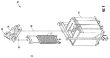
FIG. 1 is a perspective view of an example of a traction elevator system; -
FIG. 2 is a cross-sectional view of a load bearing member of an elevator system according to an embodiment; -
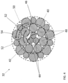
FIG. 3 is a detailed cross-sectional view of a tension element of a load bearing member according to an embodiment; -
FIG. 4 is a detailed cross-sectional view of a tension element of a load bearing member according to another embodiment; and -
FIG. 5 is a detailed cross-sectional view of a tension element of a load bearing member according to another embodiment. - A detailed description of one or more embodiments of the disclosed apparatus are presented herein by way of exemplification and not limitation with reference to the Figures.
- With reference now to
FIG. 1 , an example of an elevator system 10 is illustrated. The elevator system 10 includes an elevator car 14 configured to move vertically upwardly and downwardly within ahoistway 12 along a plurality of car guide rails (not shown). Guide assemblies mounted to the top and bottom of the elevator car 14 are configured to engage the car guide rails to maintain proper alignment of the elevator car 14 as it moves within thehoistway 12. - The elevator system 10 also includes a
counterweight 15 configured to move vertically upwardly and downwardly within thehoistway 12. Thecounterweight 15 moves in a direction generally opposite the movement of the elevator car 14 as is known in conventional elevator systems. Movement of thecounterweight 15 is guided by counterweight guide rails (not shown) mounted within thehoistway 12. In the illustrated, non-limiting embodiment, at least oneload bearing member 30, for example, a belt, is coupled to both the elevator car 14 and thecounterweight 15 and cooperates with a traction sheave 18 mounted to adrive machine 20. To cooperate with the traction sheave 18, at least oneload bearing member 30 bends in a first direction about the traction sheave 18. - The
drive machine 20 of the elevator system 10 is positioned and supported at a mounting location atop asupport member 22, such as a bedplate for example, in a portion of thehoistway 12 or a machine room. Although the elevator system 10 illustrated and described herein has a 1:1 roping configuration, it should be appreciated that an elevator system having another roping configuration is also contemplated herein. Further, an elevator system having another hoistway layout is within the scope of the present disclosure. - With reference now to
FIG. 2 , a cross-sectional view of an example of aload bearing member 30 in the form of a belt is illustrated. As shown, the belt includes at least one tension element, and in some embodiments, a plurality oftension elements 32 extending longitudinally along a length of thebelt 30. In embodiments including multiple tension elements, the plurality oftension elements 32 may be substantially identical, or alternatively may have different configurations. Further, thetension elements 32 be spaced apart or separated from one another such thatadjacent tension elements 32 are not arranged in contact. In the illustrated, non-limiting embodiment, the plurality oftension elements 32 are spaced uniformly or non-uniformly across a lateral width of theload bearing member 30. - In an embodiment, the one or
more tension elements 32 are at least partially enclosed in ajacket material 34 to not only to protect thetension elements 32, but also to restrain relative movement thereof. Thejacket material 34 may define a traction surface configured to contact a corresponding surface of the traction sheave 18. Examples of materials for thejacket material 34 include, but are not limited to polyurethane, styrene butadiene rubber (SBR), nitrile rubber (NBR), acrylonitrile butadiene styrene (ABS), SBS/SEBS plastics, silicone, EPDM rubber, other curable diene based rubber, neoprene, non-curing thermoplastic elastomers, curable extrudable rubber materials, thermoplastics such as nylon, polyester, polyvinyl chloride, polyolefin or the like, each of which can be in the form of a solution, emulsion, prepolymer or other fluid phase. However, it should be understood that any materials suitable to required functions of theload bearing member 30 are within the scope of the disclosure. For example, a primary function of thejacket material 34 is to provide a sufficient coefficient of friction between theload bearing member 30 and the traction sheave 18 to produce a desired amount of traction therebetween. Thejacket material 34 should also transmit the traction loads to thetension elements 32. In addition, thejacket material 34 should be wear resistant and protect the tension elements from impact damage, exposure to environmental factors, such as chemicals, for example. - One or more additive materials may be incorporated into the
jacket material 34 to enhance performance, such as traction and environmental resistance. For example, carbon black is very effective in improving UV-resistance of elastomers and carbodiimides are very effective in improving hydrolysis resistance of polyurethanes. - In the illustrated, non-limiting embodiment, the belt or load bearing
member 30 includes ninetension elements 32. However, it should be understood that the number oftension elements 32 illustrated is intended as an example only, and that aload bearing member 30 having any suitable number of tension elements, such as a single tension element, two, three, four, five, six, seven, eight, ten ormore tension elements 32 is within the scope of the disclosure. Further, while thetension elements 32 are shown as having a substantially circular cross-section, the depiction is merely an example.Tension elements 32 having another cross-sectional shape, such as an elliptical or oval cross-section for example, are contemplated herein. - With reference now to
FIG. 3 , a cross-sectional view of anexemplary tension element 32 is illustrated in more detail according to an embodiment. As shown, eachtension element 32 is formed from a plurality of wires. Although each of the wires of thetension element 32 is illustrated and described herein as a singular wire or filament, it should be appreciated that in other embodiments, each wire may in fact be a bundle or plurality of wires, such as having a twisted configuration. - The wires of the
tension element 32 may be arranged in a plurality of stacked or concentric layers including at least a first layer orcore 40 and asecond layer 42 located radially outward of thefirst layer 40. In the illustrated, non-limiting embodiment, thefirst layer 40 includes a plurality of substantially identicalfirst wires 44. However, in other embodiments, such as shown inFIG. 5 for example, a first diameter of the plurality offirst wires 44 may vary. For example, the plurality of first wires may include two or more wires having at least two different diameters. In the illustrated, non-limiting embodiment ofFIG. 5 , the plurality of first wires includes wires having three different diameters. Further, although thefirst layer 40 is illustrated as having threefirst wires 44, it should be understood that embodiments where thefirst layer 40 has any number offirst wires 44, including a single wire, two wires, or more than three wires, is within the scope of the disclosure. - In an embodiment, the plurality of
first wires 44 are bare or are not coated with or encapsulated within any material. However, in other embodiments acoating layer 46 may be applied about the exterior of thefirst layer 40 to encapsulate the plurality offirst wires 44. Examples of the material of thecoating layer 46 include, but are not limited to polyurethane, styrene butadiene rubber (SBR), nitrile rubber (NBR), acrylonitrile butadiene styrene (ABS), SBS/SEBS plastics, silicone, EPDM rubber, other curable diene-based rubber, neoprene, non-curing thermoplastic elastomers, curable extrudable rubber materials, thermoplastics such as nylon, polyester, polyvinyl chloride, polyolefin, or the like. The material used to form thecoating layer 46 may be substantially identical to thejacket material 34, or alternatively, may be different therefrom. - The
second layer 42 similarly includes a plurality ofsecond wires 48. Thesecond wires 48 are arranged to surround or enclose thefirst layer 40. Thesecond layer 42 typically includes a greater number of wires than thefirst layer 40, as shown inFIGS. 3 and4 . However, embodiments where the number offirst wires 44 arranged within thefirst layer 40 is greater than the number ofsecond wires 48 in thesecond layer 42, as shown inFIG. 5 , is also within the scope of the disclosure. In the illustrated, non-limiting embodiment, thesecond layer 42 includes ninesecond wires 48. However, it should be appreciated that asecond layer 42 having any suitable number of wires is contemplated herein. In an embodiment, the plurality ofsecond wires 48 may be substantially identical to one another and have a second diameter. The second diameter may be equal to or may be different than the first diameter of thefirst wires 44. In the illustrated, non-limiting embodiment, the second diameter is larger than the first diameter; however, in other embodiments the second diameter of thesecond wires 48 may be the smaller than the first diameter of thefirst wires 44. - As shown, the
tension element 32 may include one or more additional layers, such as athird layer 50 for example, located radially outward of and directly adjacent to thesecond layer 42 and having a plurality of wires configured to surround theadjacent layer 42. As a result of this configuration, thethird layer 50 typically includes more wires than thesecond layer 42. For example, in the non-limiting embodiment shown inFIG. 3 , thethird layer 50 includes fourteen wires. However, it should be appreciated that athird layer 50 having any suitable number of wires is contemplated herein. - In the illustrated, non-limiting embodiment, the
third layer 50 includes at least onethird wire 52 having a third diameter, such as a plurality ofthird wires 52, and at least onefourth wire 54 having a fourth diameter, such as a plurality of fourth wires for example. The fourth diameter may be larger than the third diameter. However, embodiments where all of the wires of thethird layer 50 are substantially identical are also contemplated herein. The third diameter may be substantially identical to or may be different from at least one of the first diameter and the second diameter. In the illustrated, non-limiting embodiment, the third diameter is substantially equal to the first diameter. Similarly, the fourth diameter may be substantially identical to or may be different from at least one of the first diameter and the second diameter. In the illustrated, non-limiting embodiment, the fourth diameter is larger than the first, second, and third diameters. - During formation of the
tension element 32, the wires within eachrespective layer tension element 32, the plurality offirst wires 44 are arranged in a desired relative position and oriented generally parallel to one another. Once properly positioned, the plurality offirst wires 44, in unison, are twisted about a central axis in either a first direction, such as a counterclockwise direction, or in a second opposite direction, such as a clockwise direction to form thefirst layer 40. After this twisting is complete, the plurality ofsecond wires 48 of thesecond layer 42 may be positioned about the outer periphery of thefirst layer 40. Once properly positioned, the position of thefirst layer 40 remains fixed and the plurality ofsecond wires 48 are then twisted about the exterior of thefirst layer 40 in either the first direction or the second direction. - The plurality of
wires third layer 50 are similarly positioned about the outer periphery of thesecond layer 42 and then twisted relative to the first andsecond layers second layer 42 in either the first direction or the second direction. It should be appreciated that in embodiments including additional layers, the same process of positioning the wires of each layer and then twisting the plurality of wires of that layer relative to the already formed layers of thetension element 32 is performed. - In an embodiment, the
first layer 40 of thetension element 32 is formed with a first lay direction and thesecond layer 42 of thetension element 32 located directly adjacent to thefirst layer 40, is formed with a second, opposite lay direction. Accordingly, in some embodiments thefirst layer 40 has a counterclockwise lay direction and thesecond layer 42 has a clockwise lay direction. Alternatively, thefirst layer 40 may have a clockwise lay direction and thesecond layer 42 has a counterclockwise lay direction. In embodiments where thetension element 32 includes one or more layers, such asthird layer 50 for example, arranged radially outward of thesecond layer 42, the lay direction of thelayer 50 located radially outward from and directly adjacent to thesecond layer 42 may be the same direction as the second layer 42 (seeFIG. 3 ), or alternatively, may be the opposite direction as thesecond layer 42, as shown inFIG. 4 . - To maintain safe operation of the elevator system 10, it is desirable to monitor the
load bearing member 30 periodically or continuously for degradation and/or damage. One method of performing such monitoring includes measuring the electrical resistance of thetension elements 32 of theload bearing member 30 with an inspection device. Examples of such inspection devices are known in the art. Aload bearing member 30 and an inspection device (not shown) operably coupled to the load bearing member in combination may be considered a load bearing system. - When the lay direction of the
first layer 40 and the lay direction of thesecond layer 42 are the same, it is believed that thesecond wires 48 are arranged in contact with thefirst wires 44 along a line (line contact). As a result of this line contact, the wire-to-wire contact stresses created during a bending operation of such atension element 32, such as about traction sheave 18 for example, are minimized, making detection of fretting or deterioration of thetension element 32 difficult. While not wanting to be bound by any specific theory, it is believed that forming thefirst layer 40 and thesecond layer 42 of thetension element 32 with opposite lay directions results in point contact rather than line contact between thewires 48 of thesecond layer 42 and thewires 44 of thefirst layer 40. The frequency of the point contact and the resulting increase in contact stresses will promote fretting behavior and create detectable increase in electrical resistance after repeated bending operations. - The term "about" is intended to include the degree of error associated with measurement of the particular quantity based upon the equipment available at the time of filing the application. For example, "about" can include a range of ± 8% or 5%, or 2% of a given value.
- The terminology used herein is for the purpose of describing particular embodiments only and is not intended to be limiting of the present disclosure. As used herein, the singular forms "a," "an" and "the" are intended to include the plural forms as well, unless the context clearly indicates otherwise. It will be further understood that the terms "comprises" and/or "comprising," when used in this specification, specify the presence of stated features, integers, steps, operations, elements, and/or components, but do not preclude the presence or addition of one or more other features, integers, steps, operations, element components, and/or groups thereof.
- While the present disclosure has been described with reference to an exemplary embodiment or embodiments, it will be understood by those skilled in the art that various changes may be made and equivalents may be substituted for elements thereof without departing from the scope of the present disclosure. In addition, many modifications may be made to adapt a particular situation or material to the teachings of the present disclosure without departing from the essential scope thereof. Therefore, it is intended that the present disclosure not be limited to the particular embodiment disclosed as the best mode contemplated for carrying out this present disclosure, but that the present disclosure will include all embodiments falling within the scope hereof.
Claims (15)
- A tension element for use in a load bearing member of an elevator system, the tension element comprising:a first layer having a plurality of first wires, wherein the first layer has a first lay direction;a second layer having a plurality of second wires, the second layer being positioned radially outward of and surrounding the first layer, the second layer having a second lay direction, wherein the second lay direction is opposite the first lay direction.
- The tension element of claim 1, wherein the first lay direction is counterclockwise and the second lay direction is clockwise; or
wherein the first lay direction is clockwise and the second lay direction is counterclockwise. - The tension element of claim 1 or 2, further comprising a coating layer encapsulating the plurality of first wires.
- The tension element of any of claims 1 to 3, wherein the plurality of second wires is greater than the plurality of first wires.
- The tension element of any of claims 1 to 3, wherein the plurality of second wires is less than the plurality of first wires.
- The tension element of any of claims 1 to 5, wherein the plurality of first wires have a first diameter and the plurality of second wires have a second diameter, the second diameter being different than the first diameter.
- The tension element of claim 6, wherein the second diameter is larger than the first diameter.
- The tension element of any of claims 1 to 7, further comprising a third layer having at least one third wire positioned radially outward of and surrounding the second layer.
- The tension element of claim 8, wherein the third layer has the first lay direction.
- The tension element of claim 8, wherein the third layer has the second lay direction.
- The tension element of any of claims 8 to 10, wherein the third layer further comprises a plurality of third wires having a third diameter and a plurality of fourth wires having a fourth diameter, the fourth diameter being larger than the third diameter.
- A load bearing system for use in an elevator system comprising:
a load bearing member comprising:at least one tension element according to any of claims 1 to 11; anda jacket material encapsulating the at least one tension element. - The load bearing system of claim 12, further comprising an inspection device operably coupled to the at least one tension element and operable to monitor an electrical resistance of the at least one tension element.
- The load bearing system of claim 13, wherein the at least one tension element further comprises a plurality of tension elements spaced laterally across a width of the load bearing member, wherein the inspection device is operably coupled to each of the plurality of tension elements.
- The load bearing system of any of claims 12 to 14, wherein the plurality of wires are further arranged in a third layer, the third layer being positioned radially outward of and surrounding the second layer;
wherein particularly the third layer has either the first lay direction or the second lay direction.
Applications Claiming Priority (1)
| Application Number | Priority Date | Filing Date | Title |
|---|---|---|---|
| US18/185,333 US12612287B1 (en) | 2023-03-16 | 2023-03-16 | High strength cord with improved detectability |
Publications (1)
| Publication Number | Publication Date |
|---|---|
| EP4431431A1 true EP4431431A1 (en) | 2024-09-18 |
Family
ID=90097701
Family Applications (1)
| Application Number | Title | Priority Date | Filing Date |
|---|---|---|---|
| EP24160013.9A Pending EP4431431A1 (en) | 2023-03-16 | 2024-02-27 | A tension element for use in a load bearing member of an elevator system |
Country Status (5)
| Country | Link |
|---|---|
| US (1) | US12612287B1 (en) |
| EP (1) | EP4431431A1 (en) |
| JP (1) | JP2024132843A (en) |
| KR (1) | KR20240140770A (en) |
| CN (1) | CN118666116A (en) |
Citations (3)
| Publication number | Priority date | Publication date | Assignee | Title |
|---|---|---|---|---|
| US20110220438A1 (en) * | 2008-11-19 | 2011-09-15 | Mirco Annen | Load supporting belt |
| US20130270044A1 (en) * | 2010-12-22 | 2013-10-17 | Otis Elevator Company | Elevator suspension and/or driving arrangement |
| US20170362059A1 (en) * | 1998-02-26 | 2017-12-21 | Otis Elevator Company | Tension member for an elevator |
Family Cites Families (34)
| Publication number | Priority date | Publication date | Assignee | Title |
|---|---|---|---|---|
| ES2129557T3 (en) * | 1991-12-27 | 1999-06-16 | Nippon Cable System Inc | CABLE FOR DRIVE. |
| CA2109904C (en) * | 1992-12-18 | 2004-09-14 | Pol Bruyneel | Multi-strand steel cord |
| FR2707309B1 (en) * | 1993-07-09 | 1995-08-11 | Trefileurope France Sa | Lifting cable. |
| CZ282660B6 (en) * | 1994-03-02 | 1997-08-13 | Inventio Ag | Bearer rope of lifting and transport facilities |
| EP0864688A1 (en) * | 1997-03-13 | 1998-09-16 | N.V. Bekaert S.A. | Push-pull cable with polymer coating |
| CN1267604C (en) * | 1998-02-26 | 2006-08-02 | 奥蒂斯电梯公司 | Tensions, traction drives and pulleys and pulley bushings for elevators |
| IL132299A (en) * | 1998-10-23 | 2003-10-31 | Inventio Ag | Stranded synthetic fiber rope |
| US6633159B1 (en) * | 1999-03-29 | 2003-10-14 | Otis Elevator Company | Method and apparatus for magnetic detection of degradation of jacketed elevator rope |
| JP4316879B2 (en) * | 2000-12-01 | 2009-08-19 | ナムローゼ・フェンノートシャップ・ベーカート・ソシエテ・アノニム | Steel cord to reinforce off-road tires and conveyor belts |
| FI118732B (en) * | 2000-12-08 | 2008-02-29 | Kone Corp | Elevator |
| US9573792B2 (en) * | 2001-06-21 | 2017-02-21 | Kone Corporation | Elevator |
| FI119234B (en) * | 2002-01-09 | 2008-09-15 | Kone Corp | Elevator |
| EP1516845B1 (en) * | 2002-06-27 | 2010-01-20 | Mitsubishi Denki Kabushiki Kaisha | Rope for elevator and method of manufacturing the rope |
| US7162858B2 (en) * | 2005-05-20 | 2007-01-16 | Teleflex Incorporated | Push-pull cable and method of manufacturing thereof |
| CN102574665B (en) * | 2009-10-14 | 2015-11-25 | 因温特奥股份公司 | Elevator system and the load-carrying element for this system |
| EP2655234B1 (en) * | 2010-12-22 | 2023-05-17 | Otis Elevator Company | Elevator system |
| BR112013023749A2 (en) * | 2011-04-14 | 2016-12-13 | Otis Elevator Co | rope or belt, and rope used on a sheathed rope or belt to suspend and / or drive an elevator car, and method of forming a rope or belt |
| ES2594003T3 (en) * | 2011-10-13 | 2016-12-15 | Bekaert Advanced Cords Aalter Nv | A load assembly comprising a steel cable and a liner |
| CN103917472B (en) * | 2011-11-10 | 2016-12-07 | 奥的斯电梯公司 | Elevator device traction belt |
| WO2013089723A1 (en) * | 2011-12-15 | 2013-06-20 | Otis Elevator Company | Elevator system belt |
| CN104024519A (en) * | 2012-01-05 | 2014-09-03 | 贝卡尔特公司 | Rope for lifting and elevator comprising rope |
| IN2014DN10732A (en) * | 2012-07-03 | 2015-09-04 | Otis Elevator Co | |
| AT516444B1 (en) * | 2014-11-05 | 2016-09-15 | Teufelberger Fiber Rope Gmbh | Rope made of textile fiber material |
| EP3233702B1 (en) * | 2014-12-19 | 2023-06-07 | Bekaert Advanced Cords Aalter NV | Elevator rope and method of manufacturing said elevator rope |
| US10676320B2 (en) * | 2015-10-16 | 2020-06-09 | Mitsubishi Electric Corporation | Elevator rope and a manufacturing method therefor |
| US11485611B2 (en) * | 2016-07-19 | 2022-11-01 | Bekaert Advanced Cords Aalter Nv | Elevator tension member with a hard thermoplastic polyurethane elastomer jacket |
| WO2018141554A1 (en) * | 2017-01-31 | 2018-08-09 | Inventio Ag | Suspension member arrangement for an elevator and monitoring arrangement for monitoring a suspension member |
| US20180222721A1 (en) * | 2017-02-06 | 2018-08-09 | Otis Elevator Company | Elevator tension member |
| KR102653649B1 (en) * | 2017-06-27 | 2024-04-03 | 베카에르트 어드밴스드 코드즈 알테 엔브이 | Reinforcement strands for reinforcement of polymer articles |
| WO2019002163A1 (en) * | 2017-06-27 | 2019-01-03 | Bekaert Advanced Cords Aalter Nv | Belt reinforced with steel strands |
| ES2939826T3 (en) * | 2017-10-27 | 2023-04-27 | Bekaert Advanced Cords Aalter Nv | Steel cord for elastomeric reinforcement |
| ES2963650T3 (en) * | 2017-10-27 | 2024-04-01 | Bekaert Advanced Cords Aalter Nv | Belt comprising steel cords adapted for wear detection |
| CN107953728B (en) * | 2017-11-27 | 2020-02-11 | 江苏兴达钢帘线股份有限公司 | Cable type tire bead and tire |
| ES2960882T3 (en) * | 2018-10-23 | 2024-03-07 | Bekaert Advanced Cords Aalter Nv | Steel wire rope and method of producing it |
-
2023
- 2023-03-16 US US18/185,333 patent/US12612287B1/en active Active
- 2023-11-23 CN CN202311567825.7A patent/CN118666116A/en active Pending
- 2023-11-28 KR KR1020230168278A patent/KR20240140770A/en active Pending
- 2023-11-29 JP JP2023201341A patent/JP2024132843A/en active Pending
-
2024
- 2024-02-27 EP EP24160013.9A patent/EP4431431A1/en active Pending
Patent Citations (3)
| Publication number | Priority date | Publication date | Assignee | Title |
|---|---|---|---|---|
| US20170362059A1 (en) * | 1998-02-26 | 2017-12-21 | Otis Elevator Company | Tension member for an elevator |
| US20110220438A1 (en) * | 2008-11-19 | 2011-09-15 | Mirco Annen | Load supporting belt |
| US20130270044A1 (en) * | 2010-12-22 | 2013-10-17 | Otis Elevator Company | Elevator suspension and/or driving arrangement |
Also Published As
| Publication number | Publication date |
|---|---|
| JP2024132843A (en) | 2024-10-01 |
| KR20240140770A (en) | 2024-09-24 |
| US12612287B1 (en) | 2026-04-28 |
| CN118666116A (en) | 2024-09-20 |
Similar Documents
| Publication | Publication Date | Title |
|---|---|---|
| JP4108607B2 (en) | Elevator rope and elevator equipment | |
| TWI420009B (en) | Synthetic fibre cable and producing method thereof, lift installation with such a synthetic fibre cable, and synthetic fiber cable for supporting and drive means for the lift | |
| US7326139B2 (en) | Belt with integrated monitoring | |
| CN104114762B (en) | For the Abrasion detecting of coated lift band or rope | |
| US7086217B2 (en) | Rope of synthetic fiber with reinforcement element for frictionally engaged power transmission and rope of synthetic fiber with reinforcement element for positively engaged power transmission | |
| AU2018202726B2 (en) | Elevator system belt with fabric tension member | |
| JP2014514226A (en) | Covered rope or belt for elevator systems | |
| AU2018202655B2 (en) | Tension member for elevator system belt | |
| WO2006061888A1 (en) | Rope for elevator and elevator | |
| JP4296152B2 (en) | Elevator rope and elevator equipment | |
| KR101635468B1 (en) | Elevator system belt | |
| CN110002322B (en) | Method and device for correcting inter-rope spacing | |
| CN103917472A (en) | Elevator system belt | |
| US12612287B1 (en) | High strength cord with improved detectability | |
| WO2019049514A1 (en) | ELEVATOR CABLE | |
| KR102168962B1 (en) | Elevator ropes and elevator devices | |
| KR20130125797A (en) | Elevator suspension and/or driving arrangement | |
| BR102023022576A2 (en) | TENSION ELEMENT AND LOAD SUPPORT SYSTEM | |
| WO2014080481A1 (en) | Flat control cable for elevator | |
| KR20240121351A (en) | Rope and belt using it | |
| EP4647384A1 (en) | Twist resistant elevator suspension member | |
| US20260116702A1 (en) | Resistance-based inspection of elevator system support members | |
| CN116507574B (en) | Composite stranded wire and method for manufacturing same, rope, belt and elevator | |
| JP7483153B2 (en) | Rope and its manufacturing method | |
| CN121913400A (en) | Elevator belt with steel cords |
Legal Events
| Date | Code | Title | Description |
|---|---|---|---|
| PUAI | Public reference made under article 153(3) epc to a published international application that has entered the european phase |
Free format text: ORIGINAL CODE: 0009012 |
|
| STAA | Information on the status of an ep patent application or granted ep patent |
Free format text: STATUS: THE APPLICATION HAS BEEN PUBLISHED |
|
| AK | Designated contracting states |
Kind code of ref document: A1 Designated state(s): AL AT BE BG CH CY CZ DE DK EE ES FI FR GB GR HR HU IE IS IT LI LT LU LV MC ME MK MT NL NO PL PT RO RS SE SI SK SM TR |
|
| STAA | Information on the status of an ep patent application or granted ep patent |
Free format text: STATUS: REQUEST FOR EXAMINATION WAS MADE |
|
| 17P | Request for examination filed |
Effective date: 20241010 |
|
| RBV | Designated contracting states (corrected) |
Designated state(s): AL AT BE BG CH CY CZ DE DK EE ES FI FR GB GR HR HU IE IS IT LI LT LU LV MC ME MK MT NL NO PL PT RO RS SE SI SK SM TR |
|
| GRAP | Despatch of communication of intention to grant a patent |
Free format text: ORIGINAL CODE: EPIDOSNIGR1 |
|
| STAA | Information on the status of an ep patent application or granted ep patent |
Free format text: STATUS: GRANT OF PATENT IS INTENDED |
|
| GRAJ | Information related to disapproval of communication of intention to grant by the applicant or resumption of examination proceedings by the epo deleted |
Free format text: ORIGINAL CODE: EPIDOSDIGR1 |
|
| STAA | Information on the status of an ep patent application or granted ep patent |
Free format text: STATUS: REQUEST FOR EXAMINATION WAS MADE |
|
| RIC1 | Information provided on ipc code assigned before grant |
Ipc: B66B 7/06 20060101AFI20260205BHEP Ipc: D07B 1/14 20060101ALI20260205BHEP Ipc: B66B 7/12 20060101ALN20260205BHEP Ipc: D07B 1/16 20060101ALN20260205BHEP Ipc: D07B 1/22 20060101ALN20260205BHEP |
|
| INTG | Intention to grant announced |
Effective date: 20260213 |
|
| GRAP | Despatch of communication of intention to grant a patent |
Free format text: ORIGINAL CODE: EPIDOSNIGR1 |
|
| STAA | Information on the status of an ep patent application or granted ep patent |
Free format text: STATUS: GRANT OF PATENT IS INTENDED |
|
| INTC | Intention to grant announced (deleted) | ||
| INTG | Intention to grant announced |
Effective date: 20260331 |
|
| RIC1 | Information provided on ipc code assigned before grant |
Ipc: B66B 7/06 20060101AFI20260320BHEP Ipc: D07B 1/14 20060101ALI20260320BHEP Ipc: B66B 7/12 20060101ALN20260320BHEP Ipc: D07B 1/16 20060101ALN20260320BHEP Ipc: D07B 1/22 20060101ALN20260320BHEP |