EP4431308A1 - Pneumatic tire with sidewall gum layer - Google Patents
Pneumatic tire with sidewall gum layer Download PDFInfo
- Publication number
- EP4431308A1 EP4431308A1 EP24163562.2A EP24163562A EP4431308A1 EP 4431308 A1 EP4431308 A1 EP 4431308A1 EP 24163562 A EP24163562 A EP 24163562A EP 4431308 A1 EP4431308 A1 EP 4431308A1
- Authority
- EP
- European Patent Office
- Prior art keywords
- ply
- radially
- tire
- belt
- sidewall
- Prior art date
- Legal status (The legal status is an assumption and is not a legal conclusion. Google has not performed a legal analysis and makes no representation as to the accuracy of the status listed.)
- Pending
Links
Images



Classifications
-
- B—PERFORMING OPERATIONS; TRANSPORTING
- B60—VEHICLES IN GENERAL
- B60C—VEHICLE TYRES; TYRE INFLATION; TYRE CHANGING; CONNECTING VALVES TO INFLATABLE ELASTIC BODIES IN GENERAL; DEVICES OR ARRANGEMENTS RELATED TO TYRES
- B60C9/00—Reinforcements or ply arrangement of pneumatic tyres
- B60C9/02—Carcasses
- B60C9/14—Carcasses built-up with sheets, webs, or films of homogeneous material, e.g. synthetics, sheet metal, rubber
-
- B—PERFORMING OPERATIONS; TRANSPORTING
- B60—VEHICLES IN GENERAL
- B60C—VEHICLE TYRES; TYRE INFLATION; TYRE CHANGING; CONNECTING VALVES TO INFLATABLE ELASTIC BODIES IN GENERAL; DEVICES OR ARRANGEMENTS RELATED TO TYRES
- B60C15/00—Tyre beads, e.g. ply turn-up or overlap
- B60C15/06—Flipper strips, fillers, or chafing strips and reinforcing layers for the construction of the bead
- B60C15/0603—Flipper strips, fillers, or chafing strips and reinforcing layers for the construction of the bead characterised by features of the bead filler or apex
-
- B—PERFORMING OPERATIONS; TRANSPORTING
- B60—VEHICLES IN GENERAL
- B60C—VEHICLE TYRES; TYRE INFLATION; TYRE CHANGING; CONNECTING VALVES TO INFLATABLE ELASTIC BODIES IN GENERAL; DEVICES OR ARRANGEMENTS RELATED TO TYRES
- B60C9/00—Reinforcements or ply arrangement of pneumatic tyres
- B60C9/18—Structure or arrangement of belts or breakers, crown-reinforcing or cushioning layers
- B60C9/1835—Rubber strips or cushions at the belt edges
- B60C9/185—Rubber strips or cushions at the belt edges between adjacent or radially below the belt plies
-
- B—PERFORMING OPERATIONS; TRANSPORTING
- B60—VEHICLES IN GENERAL
- B60C—VEHICLE TYRES; TYRE INFLATION; TYRE CHANGING; CONNECTING VALVES TO INFLATABLE ELASTIC BODIES IN GENERAL; DEVICES OR ARRANGEMENTS RELATED TO TYRES
- B60C9/00—Reinforcements or ply arrangement of pneumatic tyres
- B60C9/18—Structure or arrangement of belts or breakers, crown-reinforcing or cushioning layers
- B60C9/1835—Rubber strips or cushions at the belt edges
- B60C2009/1842—Width or thickness of the strips or cushions
-
- B—PERFORMING OPERATIONS; TRANSPORTING
- B60—VEHICLES IN GENERAL
- B60C—VEHICLE TYRES; TYRE INFLATION; TYRE CHANGING; CONNECTING VALVES TO INFLATABLE ELASTIC BODIES IN GENERAL; DEVICES OR ARRANGEMENTS RELATED TO TYRES
- B60C9/00—Reinforcements or ply arrangement of pneumatic tyres
- B60C9/18—Structure or arrangement of belts or breakers, crown-reinforcing or cushioning layers
- B60C9/1835—Rubber strips or cushions at the belt edges
- B60C2009/1864—Rubber strips or cushions at the belt edges wrapped around the edges of the belt
-
- B—PERFORMING OPERATIONS; TRANSPORTING
- B60—VEHICLES IN GENERAL
- B60C—VEHICLE TYRES; TYRE INFLATION; TYRE CHANGING; CONNECTING VALVES TO INFLATABLE ELASTIC BODIES IN GENERAL; DEVICES OR ARRANGEMENTS RELATED TO TYRES
- B60C9/00—Reinforcements or ply arrangement of pneumatic tyres
- B60C9/18—Structure or arrangement of belts or breakers, crown-reinforcing or cushioning layers
- B60C2009/1878—Structure or arrangement of belts or breakers, crown-reinforcing or cushioning layers with flat cushions or shear layers between the carcass and the belt
-
- B—PERFORMING OPERATIONS; TRANSPORTING
- B60—VEHICLES IN GENERAL
- B60C—VEHICLE TYRES; TYRE INFLATION; TYRE CHANGING; CONNECTING VALVES TO INFLATABLE ELASTIC BODIES IN GENERAL; DEVICES OR ARRANGEMENTS RELATED TO TYRES
- B60C13/00—Tyre sidewalls; Protecting, decorating, marking, or the like, thereof
- B60C13/04—Tyre sidewalls; Protecting, decorating, marking, or the like, thereof having annular inlays or covers, e.g. white sidewalls
- B60C2013/045—Tyre sidewalls; Protecting, decorating, marking, or the like, thereof having annular inlays or covers, e.g. white sidewalls comprising different sidewall rubber layers
-
- B—PERFORMING OPERATIONS; TRANSPORTING
- B60—VEHICLES IN GENERAL
- B60C—VEHICLE TYRES; TYRE INFLATION; TYRE CHANGING; CONNECTING VALVES TO INFLATABLE ELASTIC BODIES IN GENERAL; DEVICES OR ARRANGEMENTS RELATED TO TYRES
- B60C15/00—Tyre beads, e.g. ply turn-up or overlap
- B60C15/06—Flipper strips, fillers, or chafing strips and reinforcing layers for the construction of the bead
- B60C2015/0617—Flipper strips, fillers, or chafing strips and reinforcing layers for the construction of the bead comprising a cushion rubber other than the chafer or clinch rubber
Definitions
- the present disclosure relates generally to tires and, more particularly, to pneumatic tires with improved durability.
- a pneumatic tire typically includes a pair of axially separated inextensible beads having at least one carcass ply extending between the two beads.
- the carcass ply includes axially opposite end portions each of which can be turned up around a respective bead and secured thereto.
- Tread rubber and sidewall rubber are located axially from and radially outward of, respectively, the carcass ply.
- the rubber of the tire sidewall deforms, which creates heat and accelerates wear of the sidewall.
- the thickness of rubber of the tire side portion can be increased.
- the associated increased weight can increase the rolling resistance of the tire, which reduces tire performance and fuel economy as well as increases wear in other locations of the tire. Therefore, solutions to reduce the heat generation or accumulation at the sidewall with minimal increase in overall tire weight is desired.
- the invention relates to a tire in accordance with claim 1 or 14, respectively.
- the disclosure provides in a first preferred aspect a tire comprising first and second annular bead cores axially spaced from one another and a carcass including at least one ply wrapped around the first and second bead cores, each ply of the at least one ply defining a pair of turned up ends extending from the bead cores to outer end points of each ply.
- First and second bead regions are wrapped by the at least one ply such that the first and second bead regions are bounded laterally by the at least one ply and the turned up ends, and bounded radially by radially innermost edges of respective annular bead cores and radially outermost end points of respective turned up ends.
- a belt structure is disposed radially outward of the carcass, the belt structure including a radially innermost belt having first and second lateral end portions terminating in respective first and second lateral edges of the radially innermost belt respectively.
- First and second sidewall gum layers extend along a surface of the at least one ply from a first end to a second end, the first end disposed axially inward of a respective lateral edge of the radially innermost belt and radially between the at least one ply and a respective lateral end portion of the radially innermost belt, the second end disposed within a respective bead region of the first and second bead regions.
- the disclosure is directed to a tire comprising a tread cap, a carcass, a belt structure, a pair of sidewall portions, a pair of bead regions and a pair of sidewall gum layers.
- the carcass comprises at least one ply wrapped around first and second axially spaced bead cores, each ply of the at least one ply defining a pair of turned up ends extending from the bead cores to outer end points of each ply.
- the belt structure is interposed between the carcass and the tread cap.
- the belt structure comprises a radially innermost belt terminating at opposed first and second lateral edges. Radially outermost portions of each sidewall portion overlie lateral end portions of the tread cap.
- the pair of bead regions each include an annular bead core of the first and second bead cores, wherein the carcass wraps around the pair of bead regions such that the regions are bounded laterally by the at least one ply and the turned up ends, and bounded radially by radially innermost edges of the respective annular bead cores and radially outermost end points of respective turned up ends.
- a first sidewall gum layer extends along a surface of the at least one ply from a first end axially inward of the first lateral edge of the radially innermost belt to a second end within a first bead region of the pair of bead regions
- a second sidewall gum layer extends along the surface of the at least one ply from a first end axially inward of the second lateral edge of the first belt to a second end within a second bead region of the pair of bead regions.
- the disclosure is directed to a tire comprising a carcass that comprises at least one ply wrapped around first and second axially spaced bead cores. Each ply of the at least one ply defines a pair of turned up ends extending from the bead cores to outer end points of each ply.
- a belt structure is disposed radially outward of the carcass. The belt structure comprises a radially innermost belt having two lateral end portions.
- the tier further includes a pair of bead regions, wherein the at least one ply wraps around the pair of bead regions such that the regions are bounded laterally by the at least one ply and the turned up ends, and bounded radially by radially innermost edges of the respective annular bead cores and radially outermost end points of respective turned up ends.
- the tire further includes a pair of sidewall portions, wherein each of the sidewall portions is disposed axially outward of one of the pair of bead regions.
- the tire further includes a pair of sidewall gum layers, wherein a first sidewall gum layer is disposed axially between a first sidewall portion of the pair of sidewall portions and extends along a surface of the at least one ply from a first end between the at least one ply and the first lateral end portion of the radially innermost belt to a second end within a first bead region of the pair of bead regions, and wherein a second sidewall gum layer is disposed axially between a second sidewall portion of the pair of sidewall portions and extends along the surface of the at least one ply from a first end between the at least one ply and the second lateral end portion of the radially innermost belt to a second end within a second bead region of the pair of bead regions.
- Apex means an elastomeric filler located radially above the bead core and between the one or more plies and turned up ends of the one or more plies.
- Axial and “axially” mean lines or directions that are parallel to the axis of rotation of the tire.
- Bead core means an annular tensile member reinforcing the bead region of a tire, commonly constructed of steel wire, cords or cables.
- Bead Region means that part of the tire wrapped by a carcass and including a bead core.
- the bead region may be shaped, with or without other reinforcement elements such as flippers, chippers, apexes, toe guards, and chafers, to fit the design rim.
- Belt structure means one or at least two annular layers or plies of parallel cords, woven or unwoven, underlying the tread, unanchored to the bead, and preferably having cords inclined with respect to the equatorial plane of the tire.
- the belt structure may also include plies of parallel cords inclined at relatively low angles, acting as restricting layers.
- Carcass means the tire structure apart from the belt structure, tread, undertread, and sidewall rubber over the plies, but including the beads.
- “Circumferential” means lines or directions extending along the perimeter of the surface of the annular tread perpendicular to the axial direction.
- Core means one of the reinforcement strands of which the reinforcement structures of the tire comprise.
- Cord angle means the acute angle, left or right in a plan view of the tire, formed by a cord with respect to the equatorial plane.
- the “cord angle” is measured in a cured but uninflated tire.
- “Elastomer” means a resilient material capable of recovering size and shape after deformation.
- Equatorial plane (EP) or “Equatorial Centerplane (CP) means the plane perpendicular to the axis of rotation of the tire and passing through the center of the tire tread.
- Inner means toward the inside of the tire.
- Innerliner means the layer or layers of elastomer or other material that form the inside surface of a tubeless tire and that contain the inflating fluid within the tire.
- “Lateral” and “laterally” are used to indicate axial directions across the tread of the tire.
- “Lateral edges" of the tread means a line tangent to the axially outermost tread contact patch or footprint as measured under normal load and tire inflation, the lines being parallel to the equatorial centerplane.
- Ply means a cord-reinforced layer of rubber; rubber-coated, radially deployed or otherwise parallel cords.
- Plastic Tire means a laminated mechanical device of generally toroidal shape (usually an open-torus) having beads and a tread and made of rubber, chemicals, fabric, and steel or other materials. When mounted on the wheel of a motor vehicle, the tire through its tread provides traction and contains the fluid that sustains the vehicle load.
- Ring and radially are used to mean directions radially toward or away from the axis of rotation of the tire.
- “Sidewall” means that portion of a tire between the tread and the bead.
- Standardwall-over-tread refers to a tire design and method of fabrication in which the radially outermost portions of each sidewall of a tire overlie the lateral end portions of the tread.
- Thread means a molded rubber component which includes that portion of the tire that comes into contact with the road when the tire is normally inflated and under normal load.
- the tread has a depth conventionally measured from the tread outer surface to the bottom of the deepest groove of the tire.
- the present disclosure relates generally to tires and, more particularly, tires with improved durability.
- the tires of the present disclosure may be used in multiple applications, such as race tires, passenger vehicle tires, and heavy load tires.
- the tire is preferably a pneumatic tire.
- the tires of the present disclosure include thin layers (e.g., 0.2 mm to 2 mm thick or 0.4 mm to 1.5 mm thick) of unreinforced extra rubber (referred to herein as gum layers) that are strategically placed to absorb and dissipate energy and heat generated when the sidewall flexes, for example, during rolling.
- gum layers are thin and only in a portion of the tire construction, and, therefore, contribute minimal weight to the overall tire while still improving durability.
- FIG. 1 illustrates a cross-sectional view of a pneumatic tire 10 according to at least some embodiments of the present disclosure.
- the tire 10 has a sidewall-over-tread (SOT) design.
- SOT sidewall-over-tread
- teachings of the present disclosure especially the placement, compositions, and dimensions of the wraparound gum layers and sidewall gum layers
- tread-over-sidewall designs may be applied to other tire designs include tread-over-sidewall designs.
- the tire 10 includes a tread cap 12, a belt structure 14 comprising belts 24, 26, a pair of sidewall portions 16, 18, a pair of bead regions 20a, 20b, a carcass structure 22, a pair of wedges 40a, 40b, and an innerliner 21.
- the illustrated belt structure 14 includes two belts 24, 26, any number of belts (e.g., 1 to 10) may be included in a tire 10 of the present disclosure.
- the first belt 24 is radially inward of the second belt 26.
- the first belt 24 (the radially innermost belt) of the belt structure 14 is preferably the widest belt of the belt structure 14.
- the first belt 24 has a belt width substantially equal to the tread arc width.
- the breaker angle of first belt 24 is preferably between 12 degrees and 45 degrees, preferably with a left orientation, more preferably in the range of 19 degrees to 30 degrees. The belt angles are measured with respect to the circumferential direction.
- the second belt 26 is located radially outward of the first belt 24.
- the second belt 26 preferably has a width in the range of 30% to 50% of the tread arc width.
- the second belt 26 preferably has a breaker angle between 12 degrees and 45 degrees, preferably with a right orientation, more preferably in the range of 19 degrees to 30 degrees.
- the second belt 26 is preferably made of the same wire as the first belt 24 and has the same construction with the same but opposite angular orientation as first belt 24.
- the first and second belts 24, 26 are preferably made of steel, i.e. reinforced with steel.
- the % elongation at 10% of the breaking load of the first and second belts 24, 26 preferably ranges from 0.18 to 0.26. More preferably, the first and second belts 24, 26 are extensible, so that the % elongation at 10% of breaking load is greater than 0.2.
- the % elongation is measured on a cord extracted from a vulcanized tire.
- the sidewalls 16, 18 extend substantially outward from each of the bead regions 20a, 20b in the radial direction of the tire 10.
- the illustrated tire 10 is a sidewall-over-tire (SOT) design where the radially outermost portions 16a, 18a of each sidewall 16, 18 of a tire 10 overlie the lateral end portions 12a, 12b of the tread cap 12, respectively.
- the pair of bead regions 20a, 20b include a pair of annular bead cores 36a, 36b.
- the bead regions 20a,20b each further include a respective bead filler apex 38a, 38b.
- the bead regions 20a,20b may include bead cores 36a, 36b without including bead filler apexes 38a, 38b.
- the carcass 22 is radially outward of the innerliner 21.
- the carcass 22 preferably comprises a first ply 30 and second ply 32 radially inward of the first ply 30. While the illustrated carcass 22 includes two plies 30, 32, any number of plies (e.g., 1 to 10) may be included in a tire 10 of the present disclosure.
- the plies can be installed such that the portions of some or all of the plies extend into the bead region 20a, 20b are turned up around the respective bead cores 36a, 36b to create turned up ends.
- the first and second plies 30, 32 both include turned up ends 30a, 32a and 30b, 32b around each of the respective bead cores 36a, 36b.
- the turned up ends 30a, 32a extend from the bead cores 36a, 36b to outer end points 30a', 32a', 30b', 32b' of each ply 30, 32.
- the carcass 22 wraps around the bead regions 20a, 20b such that at least one of the plies 30, 32 extend along both inner and outer axial sides of the bead region 20a, 20b.
- the turned up ends 32a, 32b of the second ply 32 extend along outer axial sides of the bead regions 20a, 20b and the first ply 30 extends along inner axial sides of the bead regions 20a, 20b.
- a wedge 40a, 40b is located, at least partially, between a respective lateral end portion 24a, 24b of the first belt 24 (the radially innermost belt) and the first ply 30 (the radially outermost ply). That is, a first wedge 40a is, at least partially, between a first lateral end portion 24a of the first belt 24 (the radially innermost belt) and the first ply 30 (the radially outermost ply), and a second wedge 40b is, at least partially, between a second lateral end portion 24b of the first belt 24 and the first ply 30.
- wedges 40a, 40b support the lateral end portions 24a, 24b and assist in maintaining a predetermined curvature of the first belt 24.
- the wedges 40a, 40b are preferably constructed of a rubber or elastomer, or any of the materials described below for the construction of the "gum layers" described herein. As illustrated, each wedge 40a, 40b extends axially outward past a respective lateral edge 24a', 24b' of the first belt 24 to be between the respective lateral end portion 12a, 12b of the tread cap 12 and the first ply 30.
- each wedge 40a, 40b extends axially outward past a respective lateral edge 24a', 24b' of the first belt 24 to be between the respective lateral end portion 12a, 12b of the tread cap 12 and the first ply 30.
- a tire 10 may not include the pair of wedges 40a, 40b (see, e.g., FIGS. 3 and 4 ). All other disclosure related to FIG. 1 would be applicable to this alternative embodiment.
- the tire 10 preferably further comprises a pair of wraparound gum layers 50a, 50b and a pair of sidewall gum layers 52a, 52b.
- Each of the wraparound gum layers 50a, 50b wraps around a respective lateral end portion 24a, 24b of the first belt 24 (the radially innermost belt).
- Each wraparound gum layer 50a, 50b extends along an outer surface of the first belt 24 (the radially innermost belt), wraps around a respective end of the first belt 24, and extends along an inner surface of the first belt 24.
- a first wraparound gum layer 50a wraps around a first lateral end portion 24a of the first belt 24 (the radially innermost belt)
- a second wraparound gum layer 50b wraps around a second lateral end portion 24b of the first belt 24 (the radially innermost belt).
- Each wraparound gum layer 50a, 50b preferably extends along the inner and outer surfaces of the first belt 24 (the radially innermost belt), cumulatively, for 10 mm to 30 mm (or 15 mm to 25 mm).
- the length that each wraparound gum layer 50a, 50b extends along the inner and outer surfaces of the first belt 24 may be different or the same.
- the tire 10 may further comprise one or more additional pairs of wraparound gum layers that each wrap around a lateral end portion of other belts in the belt structure 14.
- the tire 10 may further comprise a second pair of wraparound gum layers where each wraparound gum layer wraps around a lateral end portion of second belt 26. If a third belt is included in the belt structure, a pair of wraparound gum layers is associated with the radially innermost belt, and, if additional pair(s) of wraparound gum layers are include in the tire, a pair of wraparound gum layers may be associated with one or both of the other two belts.
- the disclosure relating to the dimensions, composition, and location for the wraparound gum layer 50a, 50b of FIG.
- a tire 10 may not include any wraparound gum layers 50a, 50b (see, e.g., FIG. 4 ). All other disclosure related to FIG. 1 would be applicable to this alternative embodiment.
- Each of the sidewall gum layers 52a, 52b extends along an outer surface of the first ply 30 (the radially outermost ply) of the carcass 22 from a first end 52a', 52b' to a second end 52a", 52b". Inner surfaces of the sidewall gum layers 52a, 52b are in contact with the first ply 30 preferably along an entire length of the sidewall gum layers 52a, 52b.
- the first end 52a', 52b' is located axially inward of the corresponding lateral edge 24a', 24b' of the first belt 24 and radially between the first ply 30 (the radially outermost ply) and the respective lateral end portion 24a,24b of the first belt 24 (the radially innermost belt).
- Each of the sidewall gum layers 52a, 52b laterally overlaps the first belt 24 (the radially innermost belt) to define a laterally overlapping region 54a, 54b.
- the laterally overlapping regions 54a, 54b extending for a length of at least 6 mm each.
- the second end 52a", 52b" is located at or within the respective bead region 20a, 20b.
- a first sidewall gum layer 52a extends along an outer surface of the first ply 30 (the radially outermost ply) from a first end 52a' between the first ply 30 and the first lateral end portion 24a of the first belt 24 (the radially innermost belt) to a second end 52a" at a first bead region 20a wrapped by at least the second ply 32
- a second sidewall gum layer 52b extends along an outer surface of the first ply 30 from a first end 52b' between the first ply 30 and the second lateral end portion 24b of the first belt 24 to a second end 52b" at a second bead region 20b wrapped by at least the second ply 32.
- each sidewall gum layer 52a, 52b are located between and contacting the first ply 30 and (a) the wedge 40a, 40b at or near the first end 52a', 52b', (b) the sidewall 16, 18, (c) the turned up ends 32a, 32b of the second ply 32 (the most radially inward ply), and (d) the bead filler apex 38a, 38b at or near the second end 52a", 52b".
- the second end 52a" of the sidewall gum layer 52a is disposed at a location designated by A0.
- the second end 52a" is located between and in contact with both the first ply 30 and the bead filler apex 38a on an axially inward side of the bead filler apex 52a".
- the sidewall gum layer 52a may extend a greater or lesser distance within the bead region 20a.
- the sidewall gum layer 52a may extend to location A1 such that the second end 52a" is located between and in contact with the first ply 30 and the bead core 36a.
- the sidewall gum layer 52a may extend to location A2 such that the second end 52a" is located between and in contact with the first ply 30 and the turned up end 32a of the second ply 32.
- the sidewall gum layer 52b may be similarly arranged with respect to the corresponding bead region 20b.
- the first end 52b' of the sidewall gum layer 52b is disposed at a location B0, which is radially between and in contact with the first ply 30 and the wedge 40b.
- the sidewall gum layers 52b may extend further along the first ply 30 to locations more axially inward from the lateral edge 24b' of the first belt 24.
- the sidewall gum layer 52b may extend beyond the wedge 40b to a location B1, which is radially between and in contact with the first ply 30 and wraparound gum layer 50b.
- the sidewall gum layer 52b may extend beyond the wraparound gum layer 50b to a location B2, which is radially between and in contact with the first ply 30 and the first belt 24.
- the sidewall gum layer 52a ( FIG. 1 ) may be similarly arranged with respect to the first belt 24.
- each sidewall gum layer 52a, 52b can be located between and contacting the first ply 30 and (a) the wraparound gum layers 50a, 50b and/or the first belt 24 (the radially innermost belt), (b) the wedge 40a, 40b at or near the first end 52a', 52b', (c) the sidewall 16, 18, (d) the turned up ends 32a, 32b of the second ply 32 (the most radially inward ply), (e) the bead filler apex 38a, 38b at or near the second end 52a", 52b" and (f) the bead core 36a, 36b at or near the second end 52a", 52b".
- the tire 10 may not include the pair of wedges 40a, 40b as illustrated in FIG. 3 .
- the first end 52b' of the sidewall gum layer 52b is disposed at a location C0, which is radially between and in contact with the first ply 30 and the wraparound gum layer 50b.
- the sidewall gum layer 52b may support the lateral end portion 24b and assist in maintaining a predetermined curvature of the first belt 24 in a manner similar to the wedge 40b ( FIG. 2 ) described above.
- a length of the laterally overlapping region 54b may be adjusted to adjust the curvature of the first belt 24.
- the sidewall gum layer 50b may extend axially to a location C1, which is radially between and in contact with the first ply 30 and the first belt 24. Since the sidewall gum layer 52b may function as a wedge 40b to maintain a predetermined curvature of the first belt 24, the wedge 40b to be removed from some designs. Removing the wedge 40b may lower costs and simplify the manufacturing process.
- the sidewall gum layer 52a ( FIG. 1 ) may be similarly arranged with respect to the first belt 24.
- each sidewall gum layer 52a, 52b can be located between and contacting the first ply 30 and (a) the wraparound gum layers 50a, 50b and/or the first belt 24 (the radially innermost belt), (b) the sidewall 16, 18, (c) the turned up ends 32a, 32b of the second ply 32 (the most radially inward ply), (d) the bead filler apex 38a, 38b at or near the second end 52a", 52b", and (e) the bead core 36a, 36b at or near the second end 52a", 52b".
- the tire 10 may not include the wraparound gum layers 50a, 50b ( FIG. 2 ).
- the first end 52b' of the sidewall gum layer 52b is preferably disposed at a location D0, which is radially between and in contact with the first ply 30 and the first belt 24.
- Laterally overlapping region 54b is defined between the first end 52b' of the sidewall gum layer 52b and the lateral edge 24b' of the first belt 24.
- the sidewall gum layer 52a ( FIG. 1 ) may be similarly arranged with respect to the first belt 24.
- the bead region 20b is wrapped by the carcass 22 and includes bead core 36b therein. As illustrated in FIG. 5 , the bead region 20b also includes the optional bead filler apex 38b and a portion of the sidewall gum layer 52b that is wrapped by the carcass 22.
- the bead region 20b is bounded laterally by the first and second plies 30, 32 on a laterally inner side thereof and by the turned up ends 30b, 32b on a laterally outer side thereof.
- the bead region 20b is bounded radially by a radially innermost edge of the annular bead core 36b and a radially outermost end point 32b' of the turned up ends 30b, 32b.
- the sidewall gum layer 52b extends along the ply 30 from the first belt 24 ( FIG. 2 ) across the end point 32b' and into the bead region 20b. Radially outwardly of the end point 32b', the sidewall gum layer 52b is laterally interposed between the carcass 22 and the sidewall 18 such that a laterally inner side of the sidewall gum layer 52b is contacted by the first ply 30 and a laterally outer side of the sidewall gum layer 52b is contacted by the sidewall 18.
- the second end 52b" of the sidewall gum layer 52b is disposed within the bead region 20b. A laterally inner side of the second end 52b" is contacted by the first ply 30 and a laterally outer side of the second end 52b" is contacted by the bead filler apex 38b.
- the sidewall gum layer 52b extends along a laterally outer side of the bead filler apex 38b such that the second end 52b" is contacted by the bead filler apex 38b and the turned up end 32b of the second ply 32.
- the bead region 20b does not include a bead filler apex, and the carcass 22 wraps the bead core 36b and a portion of the sidewall gum layer 52b.
- the sidewall gum layer 52b extends to the bead core 36b such that the second end 52b" is contacted by the bead core 36b and the turned up end 30b. As illustrated in FIG. 8 , the sidewall gum layer 52b extends to a point within the bead region 20b that is radially outward of the bead filler apex 38b. The second end 52b" is contacted by the first ply 30 on a laterally inner side thereof and by the turned up end 32b on a laterally outer side thereof. The second end 52b" is disposed radially outward of a radially innermost portion 18b of the sidewall 18. In any of the configurations illustrated in FIGS. 6 through 8 , the sidewall gum layer 52 will absorb and dissipate energy and heat generated when the sidewall 18 flexes as described above.
- each sidewall gum layer 52a, 52b may be 50 mm to 90 mm (or 55 mm to 75 mm).
- the gum layers used in the construction of the tires described herein can be formed of a rubber and/or elastomer.
- the rubber and/or the elastomer of the gum layer has a Shore A hardness between 80 and 95, tested according to ASTM S2240-15(2021) and preferably with a cure of 18 minutes at 150°C.
- the rubber and/or the elastomer of the gum layer preferably has a RPA G' 1 percent of 4 MPa or greater.
- RPA rubber processing analyzer analytical equipment as produced by the Monsanto Company, and referred to as "RPA 2000.”
- RPA G' 1 percent refers to the dynamic storage modulus "G"' at a one (1) percent strain (elongation) as determined by the RPA 2000 analytical equipment measured at 100°C.
- the gum layers preferably have a thickness of 0.2 mm to 2 mm (or 0.2 mm to 1 mm, or 0.5 mm to 1.5 mm, or 1 mm to 2 mm). Each gum layer preferably may have the same or a different thickness from each other.
- the rubber that at least partially forms parts of the tire like the innerliner, carcasses (including the carcass plies), belt structures, and tread portions may comprise a rubber.
- suitable rubbers include neoprene (polychloroprene), polybutadiene (including cis-1,4-polybutadiene), polyisoprene (including cis-1,4-polyisoprene) (natural or synthetic), butyl rubber, halobutyl rubber (including chlorobutyl rubber or bromobutyl rubber), styrene/isoprene/butadiene rubber, copolymers of 1,3-butadiene or isoprene with monomers such as styrene, acrylonitrile and methyl methacrylate, ethylene/propylene terpolymers (also known as ethylene/propylene/diene monomer (EPDM) terpolymers (e.g., ethylene/propylene/dicyclopent
- the production of the tires of the present disclosure may include assembling the tire components followed by curing according to production methods conventionally known in the art, which may be dependent on the type of tire.
- US Patent No. 10,960,627 describes methods for producing tires.
- gum layers typically come in a roll (e.g., 1 cm to 20 cm wide).
- One skilled in the art, with the benefit of this disclosure, will recognize how to apply the gum layers to achieve the various embodiments of tires described herein.
- Embodiment 1 A pneumatic tire comprising: first and second annular bead cores axially spaced from one another; a carcass including at least one ply wrapped around the first and second bead cores, each ply of the at least one ply defining a pair of turned up ends extending from the bead cores to outer end points of each ply; first and second bead regions wrapped by the at least one ply such that the first and second bead regions are bounded laterally by the at least one ply and the turned up ends, and bounded radially by radially innermost edges of respective annular bead cores and radially outermost end points of respective turned up ends; a belt structure disposed radially outward of the carcass, the belt structure including a radially innermost belt having first and second lateral end portions terminating in respective first and second lateral edges of the radially innermost belt respectively; and first and second sidewall gum layers each extending along a surface of the at least one
- Embodiment 2 The tire of Embodiment 1 wherein each of the sidewall gum layers is constructed a rubber and/or an elastomer having a Shore A hardness between 80 and 95.
- Embodiment 3 The tire of Embodiment 1 or 2, wherein each of the sidewall gum layers is constructed a rubber and/or an elastomer having a RPA G' 1 percent of 4 MPa or greater.
- Embodiment 4 The tire of any of the Embodiments 1-3, wherein each of the sidewall gum layers has a length within a range from 50 mm to 90 mm.
- Embodiment 5 The tire of any of the Embodiments 1-4, wherein each of the sidewall gum layers has a thickness within a range from 0.2 mm to 2 mm.
- Embodiment 6 The tire of any of the Embodiments 1-5, further comprising a pair of wedges, wherein a first wedge of the pair of wedges is disposed, at least partially, axially inward of the lateral edge of the first lateral end portion of the radially innermost belt and radially between the first lateral end portion and the at least one ply, and wherein a second wedge of the pair of wedges is disposed, at least partially, axially inward of the lateral edge of the second lateral end portion of the radially innermost belt and radially between the second lateral end portion and the at least one ply.
- Embodiment 7 The tire of the Embodiment 6, wherein the first end of each of the sidewall gum layers is disposed radially between, and in contact with, the at least one ply and a corresponding wedge of the pair of wedges.
- Embodiment 8 The tire of any of the Embodiments 1-7, further comprising first and second wraparound gum layers, wherein the first wraparound gum layer wraps around the first lateral end portion of the radially innermost belt, wherein the second wraparound gum layer wraps around the second lateral end portion of the radially innermost belt, and wherein the first end of each of the sidewall gum layers is disposed radially between and contacting the at least one ply and a corresponding one of first and second of wraparound gum layers.
- Embodiment 9 The tire of any of the Embodiments 1-8, wherein the first end of each of the sidewall gum layers is radially between and contacting the at least one ply and the corresponding first or second lateral end portion of the radially innermost belt.
- Embodiment 10 The tire of any of the Embodiments 1-9, wherein each of the wraparound gum layers extends along an inner surface and an outer surface of the radially innermost belt for a cumulative distance in a range of 10 mm to 30 mm.
- Embodiment 11 The tire of any of the Embodiments 1-10, wherein the pair of wraparound gum layers is a first pair of wraparound gum layers, wherein the belt structure further comprises a second belt, and wherein the tire further comprises a second pair of wraparound gum layers that wrap around lateral end portions of the second belt.
- Embodiment 12 The tire of any of the Embodiments 1-11, wherein the first bead region further comprises a first bead filler apex disposed radially outward of the first annular bead core, wherein the second bead region further comprises a second bead filler apex disposed radially outward of the second annular bead core, and wherein the second end of each of the sidewall gum layers contacts a corresponding one of the first and second bead filler apexes.
- Embodiment 13 A pneumatic tire comprising: a tread cap; a carcass that comprises at least one ply wrapped around first and second axially spaced bead cores, each ply of the at least one ply defining a pair of turned up ends extending from the bead cores to outer end points of each ply; a belt structure interposed between the carcass and the tread cap, the belt structure comprising a radially innermost belt terminating at opposed first and second lateral edges; a pair of sidewall portions, wherein radially outermost portions of each sidewall overlie lateral end portions of the tread cap; a pair of bead regions each including an annular bead core of the first and second bead cores, wherein the carcass wraps around the pair of bead regions such that the regions are bounded laterally by the at least one ply and the turned up ends, and bounded radially by radially innermost edges of the respective annular bead cores and radially outermost end points
- Embodiment 14 The tire of the Embodiment 13, further comprising a pair of wedges, wherein an inner end of each wedge is disposed radially between the first belt and the at least one ply and wherein an outer end of each wedge is disposed radially between and in contact with one of the lateral end portions of the tread cap and the at least one ply.
- Embodiment 15 The tire of the Embodiment 14, further comprising a pair wraparound gum layers, wherein a first wraparound gum layer wraps around a first lateral end portion of the first belt, and wherein a second wraparound gum layer wraps around a second lateral end portion of the first belt, and wherein the inner ends of each wedge are in contact with a corresponding wraparound gum layer.
- Embodiment 16 The tire of the Embodiment 15, wherein the first end of each of the sidewall gum layers is in contact with the at least one ply and a corresponding wedge.
- Embodiment 17 The tire of any of the Embodiments 13-16, wherein each of the bead regions includes a bead filler apex therein disposed radially outward of the annular bead core therein, and wherein the second end of each sidewall gum layer is in contact with a corresponding bead filler apex.
- Embodiment 18 The tire of any of the Embodiments 13-17, wherein each of the sidewall gum layers has a length in a range of 50 mm to 90 mm.
- Embodiment 19 The tire of any of the Embodiments 13-18, wherein each of the sidewall gum layers comprise a rubber and/or an elastomer having a Shore A hardness between 80 and 95 and a RPA G' 1 percent of 4 MPa or greater.
- Embodiment 20 A pneumatic tire comprising: a carcass that comprises at least one ply wrapped around first and second axially spaced bead cores, each ply of the at least one ply defining a pair of turned up ends extending from the bead cores to outer end points of each ply; a belt structure disposed radially outward of the carcass, the belt structure comprising a radially innermost belt having two lateral end portions; a pair of bead regions, wherein the at least one ply wraps around the pair of bead regions such that the regions are bounded laterally by the at least one ply and the turned up ends, and bounded radially by radially innermost edges of the respective annular bead cores and radially outermost end points of respective turned up ends; a pair of sidewall portions, wherein each of the sidewall portions is disposed axially outward of one of the pair of bead regions; and a pair of sidewall gum layers, wherein
- Gum layers of 0.5 mm to 0.6 mm thickness were used in the construction of seven different vehicle tire configurations, each corresponding to the construction of FIG. 1 .
- the durability of the tire was improved with only a minor increase ( 1% to 2%) in rolling resistance as compared to said configurations without the sidewall gum layers.
Landscapes
- Engineering & Computer Science (AREA)
- Mechanical Engineering (AREA)
- Tires In General (AREA)
Abstract
Description
- The present disclosure relates generally to tires and, more particularly, to pneumatic tires with improved durability.
- A pneumatic tire typically includes a pair of axially separated inextensible beads having at least one carcass ply extending between the two beads. The carcass ply includes axially opposite end portions each of which can be turned up around a respective bead and secured thereto. Tread rubber and sidewall rubber are located axially from and radially outward of, respectively, the carcass ply.
- During operation, the rubber of the tire sidewall deforms, which creates heat and accelerates wear of the sidewall. To restrict deformations, the thickness of rubber of the tire side portion can be increased. However, the associated increased weight can increase the rolling resistance of the tire, which reduces tire performance and fuel economy as well as increases wear in other locations of the tire. Therefore, solutions to reduce the heat generation or accumulation at the sidewall with minimal increase in overall tire weight is desired.
- The invention relates to a tire in accordance with
claim 1 or 14, respectively. - Dependent claims refer to preferred embodiments of the invention.
- The disclosure provides in a first preferred aspect a tire comprising first and second annular bead cores axially spaced from one another and a carcass including at least one ply wrapped around the first and second bead cores, each ply of the at least one ply defining a pair of turned up ends extending from the bead cores to outer end points of each ply. First and second bead regions are wrapped by the at least one ply such that the first and second bead regions are bounded laterally by the at least one ply and the turned up ends, and bounded radially by radially innermost edges of respective annular bead cores and radially outermost end points of respective turned up ends. A belt structure is disposed radially outward of the carcass, the belt structure including a radially innermost belt having first and second lateral end portions terminating in respective first and second lateral edges of the radially innermost belt respectively. First and second sidewall gum layers extend along a surface of the at least one ply from a first end to a second end, the first end disposed axially inward of a respective lateral edge of the radially innermost belt and radially between the at least one ply and a respective lateral end portion of the radially innermost belt, the second end disposed within a respective bead region of the first and second bead regions.
- In another preferred aspect, the disclosure is directed to a tire comprising a tread cap, a carcass, a belt structure, a pair of sidewall portions, a pair of bead regions and a pair of sidewall gum layers. The carcass comprises at least one ply wrapped around first and second axially spaced bead cores, each ply of the at least one ply defining a pair of turned up ends extending from the bead cores to outer end points of each ply. The belt structure is interposed between the carcass and the tread cap. The belt structure comprises a radially innermost belt terminating at opposed first and second lateral edges. Radially outermost portions of each sidewall portion overlie lateral end portions of the tread cap. The pair of bead regions each include an annular bead core of the first and second bead cores, wherein the carcass wraps around the pair of bead regions such that the regions are bounded laterally by the at least one ply and the turned up ends, and bounded radially by radially innermost edges of the respective annular bead cores and radially outermost end points of respective turned up ends. A first sidewall gum layer extends along a surface of the at least one ply from a first end axially inward of the first lateral edge of the radially innermost belt to a second end within a first bead region of the pair of bead regions, and a second sidewall gum layer extends along the surface of the at least one ply from a first end axially inward of the second lateral edge of the first belt to a second end within a second bead region of the pair of bead regions.
- According to another preferred aspect, the disclosure is directed to a tire comprising a carcass that comprises at least one ply wrapped around first and second axially spaced bead cores. Each ply of the at least one ply defines a pair of turned up ends extending from the bead cores to outer end points of each ply. A belt structure is disposed radially outward of the carcass. The belt structure comprises a radially innermost belt having two lateral end portions. The tier further includes a pair of bead regions, wherein the at least one ply wraps around the pair of bead regions such that the regions are bounded laterally by the at least one ply and the turned up ends, and bounded radially by radially innermost edges of the respective annular bead cores and radially outermost end points of respective turned up ends. The tire further includes a pair of sidewall portions, wherein each of the sidewall portions is disposed axially outward of one of the pair of bead regions. The tire further includes a pair of sidewall gum layers, wherein a first sidewall gum layer is disposed axially between a first sidewall portion of the pair of sidewall portions and extends along a surface of the at least one ply from a first end between the at least one ply and the first lateral end portion of the radially innermost belt to a second end within a first bead region of the pair of bead regions, and wherein a second sidewall gum layer is disposed axially between a second sidewall portion of the pair of sidewall portions and extends along the surface of the at least one ply from a first end between the at least one ply and the second lateral end portion of the radially innermost belt to a second end within a second bead region of the pair of bead regions.
- The following definitions are applicable to the present invention.
- "Apex" means an elastomeric filler located radially above the bead core and between the one or more plies and turned up ends of the one or more plies.
- "Axial" and "axially" mean lines or directions that are parallel to the axis of rotation of the tire.
- "Bead core" means an annular tensile member reinforcing the bead region of a tire, commonly constructed of steel wire, cords or cables.
- "Bead Region" means that part of the tire wrapped by a carcass and including a bead core. The bead region may be shaped, with or without other reinforcement elements such as flippers, chippers, apexes, toe guards, and chafers, to fit the design rim.
- "Belt structure" means one or at least two annular layers or plies of parallel cords, woven or unwoven, underlying the tread, unanchored to the bead, and preferably having cords inclined with respect to the equatorial plane of the tire. The belt structure may also include plies of parallel cords inclined at relatively low angles, acting as restricting layers.
- "Carcass" means the tire structure apart from the belt structure, tread, undertread, and sidewall rubber over the plies, but including the beads.
- "Circumferential" means lines or directions extending along the perimeter of the surface of the annular tread perpendicular to the axial direction.
- "Cord" means one of the reinforcement strands of which the reinforcement structures of the tire comprise.
- "Cord angle" means the acute angle, left or right in a plan view of the tire, formed by a cord with respect to the equatorial plane. The "cord angle" is measured in a cured but uninflated tire.
- "Elastomer" means a resilient material capable of recovering size and shape after deformation.
- "Equatorial plane (EP)" or "Equatorial Centerplane (CP) means the plane perpendicular to the axis of rotation of the tire and passing through the center of the tire tread.
- "Inner" means toward the inside of the tire.
- "Innerliner" means the layer or layers of elastomer or other material that form the inside surface of a tubeless tire and that contain the inflating fluid within the tire.
- "Lateral" and "laterally" are used to indicate axial directions across the tread of the tire.
- "Lateral edges" of the tread means a line tangent to the axially outermost tread contact patch or footprint as measured under normal load and tire inflation, the lines being parallel to the equatorial centerplane.
- "Outer" means toward the outside of the tire.
- "Ply" means a cord-reinforced layer of rubber; rubber-coated, radially deployed or otherwise parallel cords.
- "Pneumatic Tire" means a laminated mechanical device of generally toroidal shape (usually an open-torus) having beads and a tread and made of rubber, chemicals, fabric, and steel or other materials. When mounted on the wheel of a motor vehicle, the tire through its tread provides traction and contains the fluid that sustains the vehicle load.
- "Radial" and "radially" are used to mean directions radially toward or away from the axis of rotation of the tire.
- "Sidewall" means that portion of a tire between the tread and the bead.
- "Sidewall-over-tread" refers to a tire design and method of fabrication in which the radially outermost portions of each sidewall of a tire overlie the lateral end portions of the tread.
- "Tread" means a molded rubber component which includes that portion of the tire that comes into contact with the road when the tire is normally inflated and under normal load. The tread has a depth conventionally measured from the tread outer surface to the bottom of the deepest groove of the tire.
- The invention will be described by way of example and with reference to the accompanying drawings in which:
-
FIG. 1 illustrates a cross-sectional view of one half of an example tire of the present disclosure. -
FIG. 2 is an enlarged view of the area of interest identified inFIG. 1 illustrating a first end of a sidewall gum layer in contact with a wedge that supports a lateral end portion of a belt. -
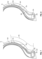
FIG. 3 is a view similar toFIG. 2 illustrating the first end of the sidewall gum layer in contact with a wraparound gum layer disposed around the lateral end portion of the belt. -
FIG. 4 is a view similar toFIG. 2 illustrating the first end of a sidewall gum layer in direct contact with the lateral end portion of the belt. -
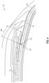
FIG. 5 is an enlarged view of the area of interest identified inFIG. 1 illustrating a sidewall gum layer extending to a bead filler apex within a bead region of the tire. -
FIG. 6 is a view similar toFIG. 5 illustrating the sidewall gum layer extending to an opposite lateral side of the bead filler apex within a bead region. -
FIG. 7 is a view similar toFIG. 5 illustrating the sidewall gum layer extending to a bead core within a bead region that does not include a bead filler apex therein. -
FIG. 8 is a view similar toFIG. 5 illustrating the sidewall gum layer extending to point radially outward of bead filler apex within a bead region. - The present disclosure relates generally to tires and, more particularly, tires with improved durability. The tires of the present disclosure may be used in multiple applications, such as race tires, passenger vehicle tires, and heavy load tires. The tire is preferably a pneumatic tire.
- The tires of the present disclosure include thin layers (e.g., 0.2 mm to 2 mm thick or 0.4 mm to 1.5 mm thick) of unreinforced extra rubber (referred to herein as gum layers) that are strategically placed to absorb and dissipate energy and heat generated when the sidewall flexes, for example, during rolling. Advantageously, the gum layers are thin and only in a portion of the tire construction, and, therefore, contribute minimal weight to the overall tire while still improving durability.
-
FIG. 1 illustrates a cross-sectional view of apneumatic tire 10 according to at least some embodiments of the present disclosure. Thetire 10 has a sidewall-over-tread (SOT) design. However, the teachings of the present disclosure (especially the placement, compositions, and dimensions of the wraparound gum layers and sidewall gum layers) may be applied to other tire designs include tread-over-sidewall designs. - The
tire 10 includes atread cap 12, abelt structure 14 comprisingbelts sidewall portions bead regions carcass structure 22, a pair ofwedges innerliner 21. - While the illustrated
belt structure 14 includes twobelts tire 10 of the present disclosure. In the illustratedtire 10, thefirst belt 24 is radially inward of thesecond belt 26. Intires 10 of the present disclosure, the first belt 24 (the radially innermost belt) of thebelt structure 14 is preferably the widest belt of thebelt structure 14. Preferably, thefirst belt 24 has a belt width substantially equal to the tread arc width. The breaker angle offirst belt 24 is preferably between 12 degrees and 45 degrees, preferably with a left orientation, more preferably in the range of 19 degrees to 30 degrees. The belt angles are measured with respect to the circumferential direction. - The
second belt 26 is located radially outward of thefirst belt 24. Thesecond belt 26 preferably has a width in the range of 30% to 50% of the tread arc width. Thesecond belt 26 preferably has a breaker angle between 12 degrees and 45 degrees, preferably with a right orientation, more preferably in the range of 19 degrees to 30 degrees. Thesecond belt 26 is preferably made of the same wire as thefirst belt 24 and has the same construction with the same but opposite angular orientation asfirst belt 24. - The first and
second belts second belts second belts - Generally, for SOT and other designs, the
sidewalls bead regions tire 10. The illustratedtire 10 is a sidewall-over-tire (SOT) design where the radiallyoutermost portions sidewall tire 10 overlie thelateral end portions tread cap 12, respectively. - The pair of
bead regions annular bead cores FIG. 1 , thebead regions bead filler apex FIG. 7 ), thebead regions bead cores bead filler apexes - The
carcass 22 is radially outward of theinnerliner 21. Thecarcass 22 preferably comprises afirst ply 30 andsecond ply 32 radially inward of thefirst ply 30. While the illustratedcarcass 22 includes twoplies tire 10 of the present disclosure. During the manufacturing sequence, the plies can be installed such that the portions of some or all of the plies extend into thebead region respective bead cores second plies ends respective bead cores ends bead cores outer end points 30a', 32a', 30b', 32b' of each ply 30, 32. Thecarcass 22 wraps around thebead regions plies bead region ends second ply 32 extend along outer axial sides of thebead regions first ply 30 extends along inner axial sides of thebead regions - On either side of the
tire 10, awedge lateral end portion first wedge 40a is, at least partially, between a firstlateral end portion 24a of the first belt 24 (the radially innermost belt) and the first ply 30 (the radially outermost ply), and asecond wedge 40b is, at least partially, between a secondlateral end portion 24b of thefirst belt 24 and thefirst ply 30.Wedges lateral end portions first belt 24. Thewedges wedge lateral edge 24a', 24b' of thefirst belt 24 to be between the respectivelateral end portion tread cap 12 and thefirst ply 30. - As illustrated, each
wedge lateral edge 24a', 24b' of thefirst belt 24 to be between the respectivelateral end portion tread cap 12 and thefirst ply 30. In alternative embodiments toFIG. 1 , atire 10 may not include the pair ofwedges FIGS. 3 and4 ). All other disclosure related toFIG. 1 would be applicable to this alternative embodiment. - The
tire 10 preferably further comprises a pair ofwraparound gum layers 50a, 50b and a pair ofsidewall gum layers wraparound gum layers 50a, 50b wraps around a respectivelateral end portion wraparound gum layer 50a, 50b extends along an outer surface of the first belt 24 (the radially innermost belt), wraps around a respective end of thefirst belt 24, and extends along an inner surface of thefirst belt 24. That is, a first wraparound gum layer 50a wraps around a firstlateral end portion 24a of the first belt 24 (the radially innermost belt), a secondwraparound gum layer 50b wraps around a secondlateral end portion 24b of the first belt 24 (the radially innermost belt). - Each
wraparound gum layer 50a, 50b preferably extends along the inner and outer surfaces of the first belt 24 (the radially innermost belt), cumulatively, for 10 mm to 30 mm (or 15 mm to 25 mm). The length that eachwraparound gum layer 50a, 50b extends along the inner and outer surfaces of thefirst belt 24 may be different or the same. - In alternate embodiments to
FIG. 1 , thetire 10 may further comprise one or more additional pairs of wraparound gum layers that each wrap around a lateral end portion of other belts in thebelt structure 14. For example, thetire 10 may further comprise a second pair of wraparound gum layers where each wraparound gum layer wraps around a lateral end portion ofsecond belt 26. If a third belt is included in the belt structure, a pair of wraparound gum layers is associated with the radially innermost belt, and, if additional pair(s) of wraparound gum layers are include in the tire, a pair of wraparound gum layers may be associated with one or both of the other two belts. The disclosure relating to the dimensions, composition, and location for thewraparound gum layer 50a, 50b ofFIG. 1 apply to any of the one or more additional pairs of wraparound gum layers relative to the belt to which said additional pair(s) of wraparound gum layers is associated. In other alternative embodiments toFIG. 1 , atire 10 may not include anywraparound gum layers 50a, 50b (see, e.g.,FIG. 4 ). All other disclosure related toFIG. 1 would be applicable to this alternative embodiment. - Each of the
sidewall gum layers carcass 22 from afirst end 52a', 52b' to asecond end 52a", 52b". Inner surfaces of thesidewall gum layers first ply 30 preferably along an entire length of thesidewall gum layers first end 52a', 52b' is located axially inward of the correspondinglateral edge 24a', 24b' of thefirst belt 24 and radially between the first ply 30 (the radially outermost ply) and the respectivelateral end portion sidewall gum layers region regions second end 52a", 52b" is located at or within therespective bead region sidewall gum layer 52a extends along an outer surface of the first ply 30 (the radially outermost ply) from afirst end 52a' between thefirst ply 30 and the firstlateral end portion 24a of the first belt 24 (the radially innermost belt) to asecond end 52a" at afirst bead region 20a wrapped by at least thesecond ply 32, and a secondsidewall gum layer 52b extends along an outer surface of thefirst ply 30 from afirst end 52b' between thefirst ply 30 and the secondlateral end portion 24b of thefirst belt 24 to asecond end 52b" at asecond bead region 20b wrapped by at least thesecond ply 32. - Portions of each
sidewall gum layer first ply 30 and (a) thewedge first end 52a', 52b', (b) thesidewall ends bead filler apex second end 52a", 52b". - As illustrated in
FIG. 1 , thesecond end 52a" of thesidewall gum layer 52a is disposed at a location designated by A0. Thesecond end 52a" is located between and in contact with both thefirst ply 30 and thebead filler apex 38a on an axially inward side of thebead filler apex 52a". In other embodiments, thesidewall gum layer 52a may extend a greater or lesser distance within thebead region 20a. For example, thesidewall gum layer 52a may extend to location A1 such that thesecond end 52a" is located between and in contact with thefirst ply 30 and thebead core 36a. Similarly, thesidewall gum layer 52a may extend to location A2 such that thesecond end 52a" is located between and in contact with thefirst ply 30 and the turned upend 32a of thesecond ply 32. Thesidewall gum layer 52b may be similarly arranged with respect to thecorresponding bead region 20b. - As illustrated in
FIG. 2 , thefirst end 52b' of thesidewall gum layer 52b is disposed at a location B0, which is radially between and in contact with thefirst ply 30 and thewedge 40b. In alternative embodiments toFIG. 2 , the sidewall gum layers 52b may extend further along thefirst ply 30 to locations more axially inward from thelateral edge 24b' of thefirst belt 24. For example, thesidewall gum layer 52b may extend beyond thewedge 40b to a location B1, which is radially between and in contact with thefirst ply 30 andwraparound gum layer 50b. Similarly, thesidewall gum layer 52b may extend beyond thewraparound gum layer 50b to a location B2, which is radially between and in contact with thefirst ply 30 and thefirst belt 24. Thesidewall gum layer 52a (FIG. 1 ) may be similarly arranged with respect to thefirst belt 24. In embodiments where thesidewall gum layers wedges sidewall gum layer first ply 30 and (a) thewraparound gum layers 50a, 50b and/or the first belt 24 (the radially innermost belt), (b) thewedge first end 52a', 52b', (c) thesidewall ends bead filler apex second end 52a", 52b" and (f) thebead core second end 52a", 52b". - In other alternative embodiments, the
tire 10 may not include the pair ofwedges FIG. 3 . In these embodiments, thefirst end 52b' of thesidewall gum layer 52b is disposed at a location C0, which is radially between and in contact with thefirst ply 30 and thewraparound gum layer 50b. Thesidewall gum layer 52b may support thelateral end portion 24b and assist in maintaining a predetermined curvature of thefirst belt 24 in a manner similar to thewedge 40b (FIG. 2 ) described above. A length of the laterally overlappingregion 54b may be adjusted to adjust the curvature of thefirst belt 24. For example, thesidewall gum layer 50b may extend axially to a location C1, which is radially between and in contact with thefirst ply 30 and thefirst belt 24. Since thesidewall gum layer 52b may function as awedge 40b to maintain a predetermined curvature of thefirst belt 24, thewedge 40b to be removed from some designs. Removing thewedge 40b may lower costs and simplify the manufacturing process. Thesidewall gum layer 52a (FIG. 1 ) may be similarly arranged with respect to thefirst belt 24. In embodiments where nowedge 24 is provided, portions of eachsidewall gum layer first ply 30 and (a) thewraparound gum layers 50a, 50b and/or the first belt 24 (the radially innermost belt), (b) thesidewall ends bead filler apex second end 52a", 52b", and (e) thebead core second end 52a", 52b". - Referring to
FIG. 4 , in other alternative embodiments, thetire 10 may not include thewraparound gum layers 50a, 50b (FIG. 2 ). In these embodiments, thefirst end 52b' of thesidewall gum layer 52b is preferably disposed at a location D0, which is radially between and in contact with thefirst ply 30 and thefirst belt 24. Laterally overlappingregion 54b is defined between thefirst end 52b' of thesidewall gum layer 52b and thelateral edge 24b' of thefirst belt 24. Thesidewall gum layer 52a (FIG. 1 ) may be similarly arranged with respect to thefirst belt 24. - Referring to
FIG. 5 , thesidewall gum layer 52b andbead region 20b ofFIG. 1 are illustrated in greater detail. Thebead region 20b is wrapped by thecarcass 22 and includesbead core 36b therein. As illustrated inFIG. 5 , thebead region 20b also includes the optionalbead filler apex 38b and a portion of thesidewall gum layer 52b that is wrapped by thecarcass 22. Thebead region 20b is bounded laterally by the first andsecond plies ends bead region 20b is bounded radially by a radially innermost edge of theannular bead core 36b and a radiallyoutermost end point 32b' of the turned upends - The
sidewall gum layer 52b extends along theply 30 from the first belt 24 (FIG. 2 ) across theend point 32b' and into thebead region 20b. Radially outwardly of theend point 32b', thesidewall gum layer 52b is laterally interposed between thecarcass 22 and thesidewall 18 such that a laterally inner side of thesidewall gum layer 52b is contacted by thefirst ply 30 and a laterally outer side of thesidewall gum layer 52b is contacted by thesidewall 18. Thesecond end 52b" of thesidewall gum layer 52b is disposed within thebead region 20b. A laterally inner side of thesecond end 52b" is contacted by thefirst ply 30 and a laterally outer side of thesecond end 52b" is contacted by thebead filler apex 38b. - Referring to
FIGS. 6 through 8 , in alternate embodiments, different configurations of thebead region 20b and thesidewall gum layer 52b are contemplated. As illustrated inFIG. 6 , thesidewall gum layer 52b extends along a laterally outer side of thebead filler apex 38b such that thesecond end 52b" is contacted by thebead filler apex 38b and the turned upend 32b of thesecond ply 32. As illustrated inFIG. 7 , thebead region 20b does not include a bead filler apex, and thecarcass 22 wraps thebead core 36b and a portion of thesidewall gum layer 52b. Thesidewall gum layer 52b extends to thebead core 36b such that thesecond end 52b" is contacted by thebead core 36b and the turned upend 30b. As illustrated inFIG. 8 , thesidewall gum layer 52b extends to a point within thebead region 20b that is radially outward of thebead filler apex 38b. Thesecond end 52b" is contacted by thefirst ply 30 on a laterally inner side thereof and by the turned upend 32b on a laterally outer side thereof. Thesecond end 52b" is disposed radially outward of a radially innermost portion 18b of thesidewall 18. In any of the configurations illustrated inFIGS. 6 through 8 , the sidewall gum layer 52 will absorb and dissipate energy and heat generated when thesidewall 18 flexes as described above. - The length of each
sidewall gum layer - The gum layers (e.g., the
wraparound gum layers 50a, 50b and thesidewall gum layers - The gum layers preferably have a thickness of 0.2 mm to 2 mm (or 0.2 mm to 1 mm, or 0.5 mm to 1.5 mm, or 1 mm to 2 mm). Each gum layer preferably may have the same or a different thickness from each other.
- The rubber that at least partially forms parts of the tire like the innerliner, carcasses (including the carcass plies), belt structures, and tread portions may comprise a rubber. Specific examples of suitable rubbers include neoprene (polychloroprene), polybutadiene (including cis-1,4-polybutadiene), polyisoprene (including cis-1,4-polyisoprene) (natural or synthetic), butyl rubber, halobutyl rubber (including chlorobutyl rubber or bromobutyl rubber), styrene/isoprene/butadiene rubber, copolymers of 1,3-butadiene or isoprene with monomers such as styrene, acrylonitrile and methyl methacrylate, ethylene/propylene terpolymers (also known as ethylene/propylene/diene monomer (EPDM) terpolymers (e.g., ethylene/propylene/dicyclopentadiene terpolymers)), alkoxy-silyl end functionalized solution polymerized polymers, styrene-butadiene rubber, polybutadiene rubber, isoprene butadiene rubber, styrene isoprene butadiene rubber, the like, and any combination thereof. The foregoing rubbers may also include conventional rubber compounding ingredients including processing oil, accelerators, conventional sulfur curing agents, pigments, carbon black, zinc oxide, stearic acid, tackifying resin, plasticizer, the like, and any combination thereof.
- The production of the tires of the present disclosure may include assembling the tire components followed by curing according to production methods conventionally known in the art, which may be dependent on the type of tire. For example,
US Patent No. 10,960,627 - Embodiment 1 A pneumatic tire comprising: first and second annular bead cores axially spaced from one another; a carcass including at least one ply wrapped around the first and second bead cores, each ply of the at least one ply defining a pair of turned up ends extending from the bead cores to outer end points of each ply; first and second bead regions wrapped by the at least one ply such that the first and second bead regions are bounded laterally by the at least one ply and the turned up ends, and bounded radially by radially innermost edges of respective annular bead cores and radially outermost end points of respective turned up ends; a belt structure disposed radially outward of the carcass, the belt structure including a radially innermost belt having first and second lateral end portions terminating in respective first and second lateral edges of the radially innermost belt respectively; and first and second sidewall gum layers each extending along a surface of the at least one ply from a first end to a second end, the first end disposed axially inward of a respective lateral edge of the radially innermost belt and radially between the at least one ply and a respective lateral end portion of the radially innermost belt, the second end disposed within a respective bead region of the first and second bead regions.
- Embodiment 2 The tire of Embodiment 1 wherein each of the sidewall gum layers is constructed a rubber and/or an elastomer having a Shore A hardness between 80 and 95.
- Embodiment 3 The tire of Embodiment 1 or 2, wherein each of the sidewall gum layers is constructed a rubber and/or an elastomer having a RPA G' 1 percent of 4 MPa or greater.
- Embodiment 4 The tire of any of the Embodiments 1-3, wherein each of the sidewall gum layers has a length within a range from 50 mm to 90 mm.
- Embodiment 5 The tire of any of the Embodiments 1-4, wherein each of the sidewall gum layers has a thickness within a range from 0.2 mm to 2 mm.
- Embodiment 6 The tire of any of the Embodiments 1-5, further comprising a pair of wedges, wherein a first wedge of the pair of wedges is disposed, at least partially, axially inward of the lateral edge of the first lateral end portion of the radially innermost belt and radially between the first lateral end portion and the at least one ply, and wherein a second wedge of the pair of wedges is disposed, at least partially, axially inward of the lateral edge of the second lateral end portion of the radially innermost belt and radially between the second lateral end portion and the at least one ply.
- Embodiment 7 The tire of the Embodiment 6, wherein the first end of each of the sidewall gum layers is disposed radially between, and in contact with, the at least one ply and a corresponding wedge of the pair of wedges.
- Embodiment 8 The tire of any of the Embodiments 1-7, further comprising first and second wraparound gum layers, wherein the first wraparound gum layer wraps around the first lateral end portion of the radially innermost belt, wherein the second wraparound gum layer wraps around the second lateral end portion of the radially innermost belt, and wherein the first end of each of the sidewall gum layers is disposed radially between and contacting the at least one ply and a corresponding one of first and second of wraparound gum layers.
- Embodiment 9 The tire of any of the Embodiments 1-8, wherein the first end of each of the sidewall gum layers is radially between and contacting the at least one ply and the corresponding first or second lateral end portion of the radially innermost belt.
-
Embodiment 10 The tire of any of the Embodiments 1-9, wherein each of the wraparound gum layers extends along an inner surface and an outer surface of the radially innermost belt for a cumulative distance in a range of 10 mm to 30 mm. - Embodiment 11 The tire of any of the Embodiments 1-10, wherein the pair of wraparound gum layers is a first pair of wraparound gum layers, wherein the belt structure further comprises a second belt, and wherein the tire further comprises a second pair of wraparound gum layers that wrap around lateral end portions of the second belt.
-
Embodiment 12 The tire of any of the Embodiments 1-11, wherein the first bead region further comprises a first bead filler apex disposed radially outward of the first annular bead core, wherein the second bead region further comprises a second bead filler apex disposed radially outward of the second annular bead core, and wherein the second end of each of the sidewall gum layers contacts a corresponding one of the first and second bead filler apexes. - Embodiment 13 A pneumatic tire comprising: a tread cap; a carcass that comprises at least one ply wrapped around first and second axially spaced bead cores, each ply of the at least one ply defining a pair of turned up ends extending from the bead cores to outer end points of each ply; a belt structure interposed between the carcass and the tread cap, the belt structure comprising a radially innermost belt terminating at opposed first and second lateral edges; a pair of sidewall portions, wherein radially outermost portions of each sidewall overlie lateral end portions of the tread cap; a pair of bead regions each including an annular bead core of the first and second bead cores, wherein the carcass wraps around the pair of bead regions such that the regions are bounded laterally by the at least one ply and the turned up ends, and bounded radially by radially innermost edges of the respective annular bead cores and radially outermost end points of respective turned up ends; and a pair of sidewall gum layers, wherein a first sidewall gum layer extends along a surface of the at least one ply from a first end axially inward of the first lateral edge of the radially innermost belt to a second end within a first bead region of the pair of bead regions, and wherein a second sidewall gum layer extends along the surface of the at least one ply from a first end axially inward of the second lateral edge of the first belt to a second end within a second bead region of the pair of bead regions.
-
Embodiment 14 The tire of the Embodiment 13, further comprising a pair of wedges, wherein an inner end of each wedge is disposed radially between the first belt and the at least one ply and wherein an outer end of each wedge is disposed radially between and in contact with one of the lateral end portions of the tread cap and the at least one ply. - Embodiment 15 The tire of the
Embodiment 14, further comprising a pair wraparound gum layers, wherein a first wraparound gum layer wraps around a first lateral end portion of the first belt, and wherein a second wraparound gum layer wraps around a second lateral end portion of the first belt, and wherein the inner ends of each wedge are in contact with a corresponding wraparound gum layer. -
Embodiment 16 The tire of the Embodiment 15, wherein the first end of each of the sidewall gum layers is in contact with the at least one ply and a corresponding wedge. - Embodiment 17 The tire of any of the Embodiments 13-16, wherein each of the bead regions includes a bead filler apex therein disposed radially outward of the annular bead core therein, and wherein the second end of each sidewall gum layer is in contact with a corresponding bead filler apex.
-
Embodiment 18 The tire of any of the Embodiments 13-17, wherein each of the sidewall gum layers has a length in a range of 50 mm to 90 mm. - Embodiment 19 The tire of any of the Embodiments 13-18, wherein each of the sidewall gum layers comprise a rubber and/or an elastomer having a Shore A hardness between 80 and 95 and a RPA G' 1 percent of 4 MPa or greater.
- Embodiment 20 A pneumatic tire comprising: a carcass that comprises at least one ply wrapped around first and second axially spaced bead cores, each ply of the at least one ply defining a pair of turned up ends extending from the bead cores to outer end points of each ply; a belt structure disposed radially outward of the carcass, the belt structure comprising a radially innermost belt having two lateral end portions; a pair of bead regions, wherein the at least one ply wraps around the pair of bead regions such that the regions are bounded laterally by the at least one ply and the turned up ends, and bounded radially by radially innermost edges of the respective annular bead cores and radially outermost end points of respective turned up ends; a pair of sidewall portions, wherein each of the sidewall portions is disposed axially outward of one of the pair of bead regions; and a pair of sidewall gum layers, wherein a first sidewall gum layer is disposed axially between a first sidewall portion of the pair of sidewall portions and extends along a surface of the at least one ply from a first end between the at least one ply and the first lateral end portion of the radially innermost belt to a second end within a first bead region of the pair of bead regions, and wherein a second sidewall gum layer is disposed axially between a second sidewall portion of the pair of sidewall portions and extends along the surface of the at least one ply from a first end between the at least one ply and the second lateral end portion of the radially innermost belt to a second end within a second bead region of the pair of bead regions
To facilitate a better understanding of the embodiments of the present invention, the following examples of preferred or representative embodiments are given. - Gum layers of 0.5 mm to 0.6 mm thickness were used in the construction of seven different vehicle tire configurations, each corresponding to the construction of
FIG. 1 . Under high-load testing, the durability of the tire was improved with only a minor increase ( 1% to 2%) in rolling resistance as compared to said configurations without the sidewall gum layers.
Claims (15)
- A tire comprising:first and second annular bead cores (36a, 36b) axially spaced from one another;a carcass (22) including at least one ply (30) wrapped around the first and second bead cores (36a, 36b), said ply (30) or each ply of the at least one ply (30) defining a pair of turned up ends (30a, 30b) extending to radially outer end points (30a', 30b') of the respective ply (30);first and second bead regions (20a, 20b) wrapped by the at least one ply (30) such that the first and second bead regions (20a, 20b) are bounded laterally by the at least one ply (30) and the turned up ends (30a, 30b), and bounded radially by radially innermost edges of respective annular bead cores (30a, 36b) and the radially outer end points (30a', 30b') of respective turned up ends (30a, 30b);a belt structure (14) disposed radially outward of the carcass (22), the belt structure (14) including a radially innermost belt (24) having first and second lateral end portions (24a, 24b) terminating in respective first and second lateral edges (24a', 24b') of the radially innermost belt (24) respectively; andfirst and second sidewall gum layers (52a, 52b) each extending along a surface of the at least one ply (30) from a first end (52a', 52b') to a second end (52a", 52b"), the first end (52a', 52b') being disposed axially inward of a respective lateral edge (24a', 24b') of the radially innermost belt (24) and preferably radially between the at least one ply (30) and a respective lateral end portion (24a, 24b) of the radially innermost belt (24), and the second end (52a", 52b") being disposed within a respective bead region (20a, 20b) of the first and second bead regions (20a, 20b).
- The tire of claim 1, wherein each of the sidewall gum layers (52a, 52b) is constructed a rubber and/or an elastomer having a Shore A hardness between 80 and 95.
- The tire of claim 1 or 2, wherein each of the sidewall gum layers (52a, 52b) is constructed a rubber and/or an elastomer having a RPA G' 1 percent of 4 MPa or greater.
- The tire of at least one of the previous claims, wherein each of the sidewall gum layers (52a, 52b) has a length within a range from 50 mm to 90 mm and/or a thickness within a range of from 0.2 mm to 2 mm.
- The tire of at least one of the previous claims, further comprising a pair of wedges (40a, 40b), wherein a first wedge (40a) of the pair of wedges is disposed, at least partially, axially inward of the lateral edge (24a') of the first lateral end portion (24a) of the radially innermost belt (24) and radially between the first lateral end portion (24a) and the at least one ply (30), wherein a second wedge (40b) of the pair of wedges is disposed, at least partially, axially inward of the lateral edge (24b') of the second lateral end portion (24b) of the radially innermost belt (24) and radially between the second lateral end portion (24b) and the at least one ply (30), and, optionally, wherein the first end (52a', 52b') of each of the sidewall gum layers (52a, 52b) is disposed radially between, and in contact with, the at least one ply (30) and a corresponding wedge of the pair of wedges (40a, 40b).
- The tire of at least one of the previous claims, further comprising first and second wraparound gum layers (50a, 50b), wherein the first wraparound gum layer (50a) wraps around the first lateral end portion (24a) of the radially innermost belt (24), wherein the second wraparound gum layer (50b) wraps around the second lateral end portion (24b) of the radially innermost belt (24), and wherein the first end (52a', 52b') of each of the sidewall gum layers (52a, 52b) is disposed radially between and contacting the at least one ply (30) and a corresponding one of first and second of wraparound gum layers (50a, 50b).
- The tire of at least one of the previous claims, wherein the first end (52a', 52b') of each of the sidewall gum layers (52a, 52b) is radially between and contacting the at least one ply (30) and the corresponding first or second lateral end portion (24a, 24b) of the radially innermost belt (24).
- The tire of at least one of the previous claims, wherein each of the wraparound gum layers (50a, 50b) extends along an inner surface and an outer surface of the radially innermost belt for a cumulative distance in a range of 10 mm to 50 mm, preferably 10 to 30 mm, and/or wherein each of the wraparound gum layers (50a, 50b) extends along an inner surface of the radially innermost belt (24) over a first distance of from 5 to 25 mm, preferably 5 to 15 mm, and along an outer surface of the radially innermost belt (24) over a second distance of from 5 to 25 mm, preferably 5 to 15 mm, the first and second distance being preferably the same or being preferably not more than 5 mm different.
- The tire of at least one of the previous claims, wherein the pair of wraparound gum layers (50a, 50b) is a first pair of wraparound gum layers, wherein the belt structure (14) further comprises a second belt (26), and wherein the tire (10) further comprises a second pair of wraparound gum layers that wrap around lateral end portions of the second belt (26).
- The tire of at least one of the previous claims, wherein the first bead region (20a) further comprises a first bead filler apex (38a) disposed radially outward of the first annular bead core (36a), wherein the second bead region (20b) further comprises a second bead filler apex (38b) disposed radially outward of the second annular bead core (36b), and wherein the second end (52a", 52b") of each of the sidewall gum layers (52a, 52b) contacts a corresponding one of the first and second bead filler apexes (38a, 38b) or extends over a portion of a surface of a corresponding one of the first and second bead filler apexes (38a, 38b).
- The tire of at least one of the previous claims, wherein the tire is a pneumatic tire and comprises a tread cap layer (12), said belt structure (14) being interposed between the carcass (22) and the tread cap layer (12), and wherein the tire (10) further comprises a pair of sidewall portions (16, 18) with radially outermost portions (16a, 18a) of each sidewall portion (16, 18) overlie lateral end portions (12a, 12b) of the tread cap layer (12).
- The tire of claim 11, further comprising a pair of wedges (40a, 40b), wherein an axially inner end of each wedge (40a, 40b) is disposed radially between the radially innermost belt (24) and the at least one ply (30) and wherein an axially outer end of each wedge (40a, 40b) is disposed radially between and in contact with one of the lateral end portions of the tread cap layer (12a, 12b) and the at least one ply (30).
- The tire of at least one of the previous claims, further comprising a pair wraparound gum layers (50a, 50b), wherein a first wraparound gum layer (50a) wraps around a first lateral end portion (24a) of the radially innermost belt (24), and wherein a second wraparound gum layer wraps (50b) around a second lateral end portion (24b) of said radially innermost belt (24), wherein the axially inner ends of each wedge (40a, 40b) are in contact with a corresponding wraparound gum layer (50a, 50b), and, optionally, wherein the first end (52a', 52b') of each of the sidewall gum layers (52a, 52b) is in contact with the at least one ply (30) and a corresponding wedge (40a, 40b).
- A tire comprising:first and second annular bead cores (36a, 36b) axially spaced from one another;first and second bead apexes (38a, 38b) extending radially outward of the first and second annular bead cores;at least one ply (30);a belt structure (14) having first and second lateral edges (24a', 24b'); andfirst and second sidewall gum layers (52a, 52b) each having a first end a first end (52a', 52b') and a second end (52a", 52b"), wherein the second end (52a", 52b")is located radially inward of the respective first and second bead apex (38a, 38b).
- The tire of claim 14 wherein the first end (52a', 52b') is disposed(i) axially inward of a respective lateral edge (24a', 24b') of the belt structure (14); or(ii) between a shoulder of the tire (10) and a midportion of the sidewall (16, 18); or(iii) radially outward of a midportion of the sidewall (16, 18); or(iv) axially outward of the lateral belt edge (24a', 24b').
Applications Claiming Priority (3)
| Application Number | Priority Date | Filing Date | Title |
|---|---|---|---|
| US202363490373P | 2023-03-15 | 2023-03-15 | |
| US18/426,476 US20240308273A1 (en) | 2023-03-15 | 2024-01-30 | Durable tires and related methods |
| US18/426,577 US20240424838A1 (en) | 2023-03-15 | 2024-01-30 | Durable tires and related methods |
Publications (1)
| Publication Number | Publication Date |
|---|---|
| EP4431308A1 true EP4431308A1 (en) | 2024-09-18 |
Family
ID=90365546
Family Applications (2)
| Application Number | Title | Priority Date | Filing Date |
|---|---|---|---|
| EP24163565.5A Active EP4431309B1 (en) | 2023-03-15 | 2024-03-14 | Tire with sidewall gum layer |
| EP24163562.2A Pending EP4431308A1 (en) | 2023-03-15 | 2024-03-14 | Pneumatic tire with sidewall gum layer |
Family Applications Before (1)
| Application Number | Title | Priority Date | Filing Date |
|---|---|---|---|
| EP24163565.5A Active EP4431309B1 (en) | 2023-03-15 | 2024-03-14 | Tire with sidewall gum layer |
Country Status (1)
| Country | Link |
|---|---|
| EP (2) | EP4431309B1 (en) |
Citations (5)
| Publication number | Priority date | Publication date | Assignee | Title |
|---|---|---|---|---|
| US20130098518A1 (en) * | 2011-10-21 | 2013-04-25 | Todd A. Buxton | All steel fabric radial construction for agricultural tires |
| US20150283864A1 (en) * | 2012-10-03 | 2015-10-08 | The Yokohama Rubber Co., Ltd. | Pneumatic Tire |
| US20190193485A1 (en) * | 2017-12-22 | 2019-06-27 | Toyo Tire & Rubber Co., Ltd. | Pneumatic tire |
| US10960627B2 (en) | 2017-09-01 | 2021-03-30 | The Goodyear Tire & Rubber Company | Method of making a tire |
| EP3878667A1 (en) * | 2020-03-11 | 2021-09-15 | Sumitomo Rubber Industries, Ltd. | Pneumatic tire |
Family Cites Families (3)
| Publication number | Priority date | Publication date | Assignee | Title |
|---|---|---|---|---|
| JP3626291B2 (en) * | 1996-08-07 | 2005-03-02 | 住友ゴム工業株式会社 | Pneumatic tire |
| JP5440081B2 (en) * | 2009-10-02 | 2014-03-12 | 横浜ゴム株式会社 | Pneumatic tire |
| DE102014207193B4 (en) * | 2014-04-15 | 2023-06-29 | Continental Reifen Deutschland Gmbh | Vehicle Pneumatic Tires |
-
2024
- 2024-03-14 EP EP24163565.5A patent/EP4431309B1/en active Active
- 2024-03-14 EP EP24163562.2A patent/EP4431308A1/en active Pending
Patent Citations (5)
| Publication number | Priority date | Publication date | Assignee | Title |
|---|---|---|---|---|
| US20130098518A1 (en) * | 2011-10-21 | 2013-04-25 | Todd A. Buxton | All steel fabric radial construction for agricultural tires |
| US20150283864A1 (en) * | 2012-10-03 | 2015-10-08 | The Yokohama Rubber Co., Ltd. | Pneumatic Tire |
| US10960627B2 (en) | 2017-09-01 | 2021-03-30 | The Goodyear Tire & Rubber Company | Method of making a tire |
| US20190193485A1 (en) * | 2017-12-22 | 2019-06-27 | Toyo Tire & Rubber Co., Ltd. | Pneumatic tire |
| EP3878667A1 (en) * | 2020-03-11 | 2021-09-15 | Sumitomo Rubber Industries, Ltd. | Pneumatic tire |
Also Published As
| Publication number | Publication date |
|---|---|
| EP4431309B1 (en) | 2026-04-29 |
| EP4431309A1 (en) | 2024-09-18 |
Similar Documents
| Publication | Publication Date | Title |
|---|---|---|
| US11712927B2 (en) | Tire | |
| US4265288A (en) | Pneumatic safety tire with excellent long-running ability after puncture employing rubber having specifically defined properties for sidewall inserts and tread | |
| EP2130690B1 (en) | Tire with a sidewall rubber insert | |
| EP4371785B1 (en) | Aircraft radial tire | |
| EP4140767B1 (en) | Heavy duty pneumatic tire | |
| EP3030431B1 (en) | Method for increasing the performances of a tyres for vehicle wheels and tyre for vehicle wheels | |
| EP4180243B1 (en) | Heavy duty pneumatic tire | |
| EP4019281B1 (en) | Tire | |
| US8074690B2 (en) | Decoupling groove for pneumatic tire tread | |
| EP4140766B1 (en) | Heavy duty pneumatic tire | |
| EP4344902B1 (en) | Tire for motorcycle for running on rough terrain | |
| EP4353495B1 (en) | Tire | |
| US20240308273A1 (en) | Durable tires and related methods | |
| EP4431309B1 (en) | Tire with sidewall gum layer | |
| EP3888943B1 (en) | Pneumatic tire | |
| JP4912761B2 (en) | Pneumatic tire | |
| JP4748522B2 (en) | Pneumatic tire | |
| JP3400005B2 (en) | Pneumatic radial tire | |
| EP4059740A1 (en) | Tire | |
| US20240424838A1 (en) | Durable tires and related methods | |
| CN118665085A (en) | Durable tire and related methods | |
| EP4159487B1 (en) | Wraparound structure for a belt package of a tire | |
| EP4140772A1 (en) | Tire | |
| JPH06320906A (en) | Pneumatic radial tires for heavy loads | |
| CN118665086A (en) | Durable tire and related methods |
Legal Events
| Date | Code | Title | Description |
|---|---|---|---|
| PUAI | Public reference made under article 153(3) epc to a published international application that has entered the european phase |
Free format text: ORIGINAL CODE: 0009012 |
|
| STAA | Information on the status of an ep patent application or granted ep patent |
Free format text: STATUS: THE APPLICATION HAS BEEN PUBLISHED |
|
| AK | Designated contracting states |
Kind code of ref document: A1 Designated state(s): AL AT BE BG CH CY CZ DE DK EE ES FI FR GB GR HR HU IE IS IT LI LT LU LV MC ME MK MT NL NO PL PT RO RS SE SI SK SM TR |
|
| STAA | Information on the status of an ep patent application or granted ep patent |
Free format text: STATUS: REQUEST FOR EXAMINATION WAS MADE |
|
| 17P | Request for examination filed |
Effective date: 20250313 |
|
| STAA | Information on the status of an ep patent application or granted ep patent |
Free format text: STATUS: EXAMINATION IS IN PROGRESS |
|
| 17Q | First examination report despatched |
Effective date: 20251030 |
|
| GRAP | Despatch of communication of intention to grant a patent |
Free format text: ORIGINAL CODE: EPIDOSNIGR1 |
|
| STAA | Information on the status of an ep patent application or granted ep patent |
Free format text: STATUS: GRANT OF PATENT IS INTENDED |
|
| GRAJ | Information related to disapproval of communication of intention to grant by the applicant or resumption of examination proceedings by the epo deleted |
Free format text: ORIGINAL CODE: EPIDOSDIGR1 |
|
| STAA | Information on the status of an ep patent application or granted ep patent |
Free format text: STATUS: EXAMINATION IS IN PROGRESS |
|
| INTG | Intention to grant announced |
Effective date: 20260407 |
|
| INTC | Intention to grant announced (deleted) | ||
| GRAP | Despatch of communication of intention to grant a patent |
Free format text: ORIGINAL CODE: EPIDOSNIGR1 |
|
| STAA | Information on the status of an ep patent application or granted ep patent |
Free format text: STATUS: GRANT OF PATENT IS INTENDED |
|
| INTG | Intention to grant announced |
Effective date: 20260612 |