EP4431136A2 - Abdeckung für eine medizinische injektionsvorrichtung mit einem rfid-etikett - Google Patents
Abdeckung für eine medizinische injektionsvorrichtung mit einem rfid-etikett Download PDFInfo
- Publication number
- EP4431136A2 EP4431136A2 EP24192752.4A EP24192752A EP4431136A2 EP 4431136 A2 EP4431136 A2 EP 4431136A2 EP 24192752 A EP24192752 A EP 24192752A EP 4431136 A2 EP4431136 A2 EP 4431136A2
- Authority
- EP
- European Patent Office
- Prior art keywords
- rfid tag
- wall
- cover
- casing
- outer casing
- Prior art date
- Legal status (The legal status is an assumption and is not a legal conclusion. Google has not performed a legal analysis and makes no representation as to the accuracy of the status listed.)
- Pending
Links
Images


Classifications
-
- A—HUMAN NECESSITIES
- A61—MEDICAL OR VETERINARY SCIENCE; HYGIENE
- A61M—DEVICES FOR INTRODUCING MEDIA INTO, OR ONTO, THE BODY; DEVICES FOR TRANSDUCING BODY MEDIA OR FOR TAKING MEDIA FROM THE BODY; DEVICES FOR PRODUCING OR ENDING SLEEP OR STUPOR
- A61M5/00—Devices for bringing media into the body in a subcutaneous, intra-vascular or intramuscular way; Accessories therefor, e.g. filling or cleaning devices, arm-rests
- A61M5/178—Syringes
- A61M5/31—Details
- A61M5/32—Needles; Details of needles pertaining to their connection with syringe or hub; Accessories for bringing the needle into, or holding the needle on, the body; Devices for protection of needles
- A61M5/3202—Devices for protection of the needle before use, e.g. caps
-
- A—HUMAN NECESSITIES
- A61—MEDICAL OR VETERINARY SCIENCE; HYGIENE
- A61B—DIAGNOSIS; SURGERY; IDENTIFICATION
- A61B90/00—Instruments, implements or accessories specially adapted for surgery or diagnosis and not covered by any of the groups A61B1/00 - A61B50/00, e.g. for luxation treatment or for protecting wound edges
- A61B90/90—Identification means for patients or instruments, e.g. tags
- A61B90/98—Identification means for patients or instruments, e.g. tags using electromagnetic means, e.g. transponders
-
- A—HUMAN NECESSITIES
- A61—MEDICAL OR VETERINARY SCIENCE; HYGIENE
- A61M—DEVICES FOR INTRODUCING MEDIA INTO, OR ONTO, THE BODY; DEVICES FOR TRANSDUCING BODY MEDIA OR FOR TAKING MEDIA FROM THE BODY; DEVICES FOR PRODUCING OR ENDING SLEEP OR STUPOR
- A61M2205/00—General characteristics of the apparatus
- A61M2205/35—Communication
- A61M2205/3546—Range
- A61M2205/3569—Range sublocal, e.g. between console and disposable
-
- A—HUMAN NECESSITIES
- A61—MEDICAL OR VETERINARY SCIENCE; HYGIENE
- A61M—DEVICES FOR INTRODUCING MEDIA INTO, OR ONTO, THE BODY; DEVICES FOR TRANSDUCING BODY MEDIA OR FOR TAKING MEDIA FROM THE BODY; DEVICES FOR PRODUCING OR ENDING SLEEP OR STUPOR
- A61M2205/00—General characteristics of the apparatus
- A61M2205/60—General characteristics of the apparatus with identification means
- A61M2205/6054—Magnetic identification systems
-
- A—HUMAN NECESSITIES
- A61—MEDICAL OR VETERINARY SCIENCE; HYGIENE
- A61M—DEVICES FOR INTRODUCING MEDIA INTO, OR ONTO, THE BODY; DEVICES FOR TRANSDUCING BODY MEDIA OR FOR TAKING MEDIA FROM THE BODY; DEVICES FOR PRODUCING OR ENDING SLEEP OR STUPOR
- A61M2207/00—Methods of manufacture, assembly or production
- A61M2207/10—Device therefor
-
- G—PHYSICS
- G06—COMPUTING OR CALCULATING; COUNTING
- G06K—GRAPHICAL DATA READING; PRESENTATION OF DATA; RECORD CARRIERS; HANDLING RECORD CARRIERS
- G06K19/00—Record carriers for use with machines and with at least a part designed to carry digital markings
- G06K19/06—Record carriers for use with machines and with at least a part designed to carry digital markings characterised by the kind of the digital marking, e.g. shape, nature, code
- G06K19/067—Record carriers with conductive marks, printed circuits or semiconductor circuit elements, e.g. credit or identity cards also with resonating or responding marks without active components
- G06K19/07—Record carriers with conductive marks, printed circuits or semiconductor circuit elements, e.g. credit or identity cards also with resonating or responding marks without active components with integrated circuit chips
- G06K19/077—Constructional details, e.g. mounting of circuits in the carrier
- G06K19/07749—Constructional details, e.g. mounting of circuits in the carrier the record carrier being capable of non-contact communication, e.g. constructional details of the antenna of a non-contact smart card
- G06K19/07758—Constructional details, e.g. mounting of circuits in the carrier the record carrier being capable of non-contact communication, e.g. constructional details of the antenna of a non-contact smart card arrangements for adhering the record carrier to further objects or living beings, functioning as an identification tag
-
- G—PHYSICS
- G06—COMPUTING OR CALCULATING; COUNTING
- G06K—GRAPHICAL DATA READING; PRESENTATION OF DATA; RECORD CARRIERS; HANDLING RECORD CARRIERS
- G06K19/00—Record carriers for use with machines and with at least a part designed to carry digital markings
- G06K19/06—Record carriers for use with machines and with at least a part designed to carry digital markings characterised by the kind of the digital marking, e.g. shape, nature, code
- G06K19/067—Record carriers with conductive marks, printed circuits or semiconductor circuit elements, e.g. credit or identity cards also with resonating or responding marks without active components
- G06K19/07—Record carriers with conductive marks, printed circuits or semiconductor circuit elements, e.g. credit or identity cards also with resonating or responding marks without active components with integrated circuit chips
- G06K19/077—Constructional details, e.g. mounting of circuits in the carrier
- G06K19/07749—Constructional details, e.g. mounting of circuits in the carrier the record carrier being capable of non-contact communication, e.g. constructional details of the antenna of a non-contact smart card
- G06K19/07773—Antenna details
- G06K19/07786—Antenna details the antenna being of the HF type, such as a dipole
Definitions
- the present invention relates to a cover for a medical injection device, a medical injection device and a method for manufacturing said cover.
- the invention is particularly well suited for the healthcare industry.
- distal end of a component or of a device is to be understood as meaning the end furthest from the user's hand and the proximal end is to be understood as meaning the end closest to the user's hand.
- distal direction is to be understood as meaning the direction of injection, with respect to a medical container of the invention
- proximal direction is to be understood as meaning the opposite direction to said direction of injection, that is to say the direction towards the user's hand holding a container as for an injection operation.
- Medical injection devices for example pre-fillable or prefilled syringes, usually comprise a hollow body or barrel forming a container for a medical product.
- This body comprises a distal end, optionally provided with a needle, and a proximal end, usually provided with a flange.
- a receptacle having a cylindrical lateral surface surrounded by a sequence of printed machine-readable unique identifier codes.
- These printed unique identifier codes allow tracking and tracing of each receptacle along a supply chain.
- these unique identifier codes are printed on an external side of the receptacle so that they may be removed or damaged, for example, during handling or use of the receptacle.
- the unique identifier codes cover a portion of the receptacle so that they may have an impact on a user visual inspection process.
- an inkjet printer is used to print the identifier codes on the external side of the receptacle.
- this printing method, using ink may lead to a risk of contamination of the receptacle.
- a plastic flange for a medical container comprising a remotely readable electronic component such as RFID tag including a RFID chip and a RFID antenna for remote identification of the medical container.
- said medical container requires a complex manufacturing process which includes in particular the assembly of a plastic flange on a glass barrel.
- US2019/0217018 discloses a RFID tag enabled shield assembly that provides a sterile enclosure of a medicament delivery port of a medicament container.
- the container can be a needleless pre-filled syringe, a vial, a cartridge, or a collapsible bag or pouch.
- the RFID tag is fixedly attached to one or more components of the shield assembly through co-molding or another form of permanent or removable attachment.
- the RFID tag is actually a RFID chip that can be optionally in electrical communication with an antenna.
- the dimension of the RFID tag is the smallest possible. Indeed, a small RFID tag is easier to implement without affecting the cover manufacturing process. Furthermore, a small RFID tag barely affects the thickness and the visual aspect of the shield assembly. Nevertheless, the data transmission level to the RFID reader is significantly reduced.
- an object of the present invention is to provide a device that alleviates the above-mentioned drawbacks by allowing an effective individual identification of a medical injection device with few or no impact on visual inspection, with a high data transmission level, with few or no risks of being removed or damaged, and with a limited impact on the manufacturing process.
- a first aspect of the present invention is a cover for a medical injection device, said medical injection device having a hub portion defined at its distal end, the said cover comprising:
- the cover of the invention allows individual traceability of each medical injection device from the manufacturing process to the final use of the medical injection device.
- the RFID tag is well protected from removal or external damage that may occur due to the packaging, storing distribution or the use of the medical injection device.
- the RFID tag being concealed between the outer casing and the inner casing of the cover, there is no visual impact on the medical injection device.
- the insertion of the RFID tag has only a limited impact on the cover manufacturing process. It is also contemplated that the RFID tag allows remote and therefore easy identification of the medical injection device, from the manufacturing steps of the cover to the final use of the medical injection device or its disposal.
- the RFID tag does not require a direct visual perspective from a reading machine so that the reading may occur at any time without a need to unpack the medical injection device, the medical injection device being packed in an individual packaging or packed with others medical injection devices such as in a tub and/or a sealing bag.
- the RFID tag being integrated within the cover, there is no additional thickness to an outer wall of the cover, and thus no change is required regarding the packaging or storing of the medical injection device.
- the RFID tag has a width extending between 40% and 100%, 100% being excluded, of the circumference of the outer wall of the inner casing or the whole circumference of the inner wall of the outer casing.
- the RFID tag has a length extending over at least 50% of a length of the cover. It is believed that the length of the tag, and more particularly the length of the antenna of the tag, can have an impact on the data transmission level of the RFID tag to the RFID reader.
- the inventors have discovered that it is possible to implement the RFID tag according to the present invention having a wide width and a wide length in the cover. Indeed, the location of the RFID tag in the cover, and more particularly between the outer casing and the inner casing allows increasing the dimensions of the RFID tag and therefore the data transmission level to the RFID reader significantly increases without affecting the manufacturing process.
- 100% of the width of the cover corresponds to the maximum width of the cover and 100% of the length of the cover corresponds to the maximum length of the cover.
- the cover of the present invention comprises an inner casing having an outer wall being at least partly in contact with the inner wall of the outer casing.
- the contact is made without any adhesive.
- the outer wall of the inner casing is only partly in contact with the inner wall of the outer casing.
- the inner and outer casings can be easily assembled together.
- the RFID tag comprises a RFID chip connected to at least one RFID antenna extending substantially along a longitudinal axis of the cover.
- the RFID tag is positioned within the inner wall of the outer casing.
- the RFID tag is positioned within the outer wall of the inner casing.
- the RFID tag is positioned between the outer wall of the inner casing and the inner wall of the outer casing.
- the RFID tag may adhere to the outer wall of the inner casing by adhesive bonding, or the RFID tag may adhere to the inner wall of the outer casing by adhesive bonding.
- the RFID tag is in a form of wet inlay, dry inlay, or pressure sensitive label.
- RFID Wet Inlays and RFID Dry Inlays can comprise a substrate, for example made of paper or Polyethylene terephthalate (PET).
- the RFID tag can be disposed on one side of the substrate.
- RFID Wet Inlays and RFID Dry Inlays can further comprise at least one protective layer on top of the RFID tag.
- the protective layer can be a siliconized paper.
- RFID Wet Inlays are described as “wet” as they include an adhesive layer on the other side of the substrate and a backing paper, for example with a silicon liner.
- RFID Dry Inlays are described as “Dry” due to their lack of adhesive backing.
- Pressure-sensitive labels are analogous to a high-tech sticker.
- the RFID tag is a High Frequency Radio Frequency Identification (HF-RFID) tag.
- HF-RFID High Frequency Radio Frequency Identification
- High frequencies are usually about 1-15 MHz.
- a RFID reader can for example read the HF-RFID tag at a distance about one meter.
- the ring-shaped RFID tag is a High-Frequency Near Field Communication (HF-NFC) tag.
- the frequencies are usually about 13.56 MHz.
- a NFC reader can for example read the HF-NFC tag at a distance up to a few centimeters.
- HF-NFC differs from HF-RFID in that it can be read by a NFC smartphone.
- the ring-shaped RFID tag is a double frequency tag including simultaneously a HF-NFC and an UHF RFID. For example, it can be read with both a NFC smartphone or an UHF reader.
- the RFID tag is an Ultra High Frequency Radio Frequency Identification (UHF-RFID) tag.
- Ultra high frequencies are usually about 400-1000MHz.
- a RFID reader can for example read the UHF-RFID tag at a distance about fifteen meters.
- the RFID antenna has at least one leg.
- the RFID antenna may have two or four legs for example. More preferably, the RFID antenna has two legs, each leg having an extremity.
- the RFID antenna has two legs which may have a plurality of steady steps.
- steady step means that the two legs of the RFID antenna may have a plurality of even steps.
- the steady step forms a square, rectangle, triangle or wave shape.
- the plurality of steady steps have the same amplitude.
- the RFID antenna has two sinusoidal shaped legs, straight-shaped legs or coil-shaped legs.
- both legs of the RFID antenna being made of a plurality of sinusoids.
- the RFID tag is an UHF-RFID tag
- the two legs have sinusoidal shape.
- the RFID tag is a HF-RFID tag
- the two legs have a coil shape. Indeed, it is believed that in these embodiments, the shape of the legs further improves the communication between the chip, the antenna of the RFID tag and the RFID reader.
- the RFID antenna forms a loop between the legs, the RFID chip being located between the loop and the legs of the RFID antenna.
- the RFID tag is dissymmetrical, i.e. the RFID chip is not located at equidistance of both RFID antenna extremities.
- the RFID chip is located at equidistance of both RFID antenna extremities.
- the RFID tag has a width extending between 50% and 100% and more preferably between 50 and 90%, or advantageously between 40% and 90% of the circumference of the outer wall of the inner casing or the circumference of the inner wall of the outer casing.
- the data transmission level to the RFID reader is improved without any risk of interference.
- the RFID tag has a length extending strictly less than 100% of a length of the cover.
- the RFID tag has a length extending over at least 70% of a length of the cover. In this embodiment, it is believed that the length of the tag has a significant impact on the data transmission level of the RFID tag to the RFID reader.
- the radius of curvature of the RFID tag is between the radius of curvature of the outer casing and the radius of curvature of the inner casing.
- the RFID tag has a longitudinal axis parallel to a longitudinal axis of the cover.
- the first material is preferably more rigid than the said second material.
- the first material is a thermoplastic.
- the first material may be polypropylene (PP), polyethylene (PE), polyethylene terephthalate (PET), polystyrene (PS) or polycarbonate (PC).
- the second material is a deformable material, made of a material having elastomeric properties, such as Thermo Plastic Elastomer ("TPE”), rubber or elastomer. Materials with elastomeric properties that are sterilizable are preferred.
- TPE Thermo Plastic Elastomer
- a second aspect of the present invention is a medical injection device comprising a hub portion and a cover according to the present invention.
- the hub portion of the medical injection device of the invention comprises a needle.
- a third aspect of the present invention is a method for manufacturing a cover according to the present invention, said method comprising :
- the inner casing and the outer casing may be manufactured separately or together.
- the inner casing and the outer casing can be manufactured together by co-molding or over-molding.
- the inner casing and the outer casing can be manufactured separately by molding, in particular by injection molding.
- the RFID tag is fixed within the inner wall of the outer casing, within the outer wall of the inner casing or between the outer wall of the inner casing and the inner wall of the outer casing by molding, by in-mold labelling, by adhesive bonding, by assembly, by co-molding or by over-molding.
- the RFID tag is fixed within the inner wall of the outer casing by in-mold labelling.
- the RFID tag is fixed within the outer wall of the inner casing by in-mold labelling or adhesive bonding.
- the RFID tag is fixed within the outer wall of the inner casing by in-mold labelling.
- the RFID tag is fixed within the outer wall of the inner casing by adhesive bonding.
- the RFID tag is fixed between the outer wall of the inner casing and the inner wall of the outer casing by adhesive bonding or by assembly.
- Assembly means that the RFID tag is held between the outer wall of the inner casing and the inner wall of the outer casing since the inner casing has an outer wall being at least partly in contact with the inner wall of the outer casing.
- a RFID Dry inlay is fixed within the inner wall of the outer casing, within the outer wall of the inner casing or between the outer wall of the inner casing and the inner wall of the outer casing by in-mold labelling or over-molding.
- a RFID Wet inlay is fixed within the inner wall of the outer casing, within the outer wall of the inner casing or between the outer wall of the inner casing and the inner wall of the outer casing by in-mold labelling, by adhesive bonding, by assembly, by co-molding or by over-molding.
- step B when the inner casing and the outer casing are manufactured separately, the inner casing and the outer casing can be assembled to form the cover of the invention.
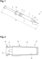
- Figure 1 shows a medical injection device 1 such as a syringe comprising a body 3 extending along a longitudinal axis A I .
- Said body 3 comprises a sidewall 11 and thus forms a reservoir, adapted to contain a medical composition 4 to be injected.
- the medical injection device 1 further comprises a hub portion 6 provided at its distal end 13 and extending along the axis A I from the distal end of the body 3.
- the hub portion 6 is partially hollow so as to form a channel 5 in fluidic communication with the body 3.
- a needle 2 may be attached to the hub portion 6 of the medical injection device.
- the needle 2 may be glued to the hub portion 6.
- the cover of the invention is intended to cover the hub portion 6 of the medical injection device, so as to protect the needle 2.
- the medical injection device 1 can also include, at its distal end, a distal shoulder 7 which narrows with respect to the body 3. At its proximal end the body can suitably include a body flange 12.
- the medical injection device or syringe 1 shown in Figure 1 also includes a plunger rod 9 having a stopper 8 provided at an end thereof.
- the stopper 8 is caused to slidably move in the body 3 along an inner surface of the sidewall 11 to cause the medical composition 4 to be expelled from the body 3 through the needle 2.
- the medical composition comprised in the medical injection device 1 may be for example, a liquid medicament, a drug or a pharmaceutical composition such as a vaccine.
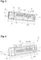
- FIGS 2 and 3 show a cover 10 according to an embodiment of the present invention.
- the cover 10 of the invention is intented to protect the needle 2 mounted on the hub portion 6 of a medical injection device 1.
- the cover 10 is intented to be mounted on the hub portion 6 of said medical injection device 1.
- the cover 10 comprises an outer casing 20 and an inner casing 30.
- the outer casing 20 is typically made of a rigid material while the inner casing 30 - wherein the needle 2 is directly engaged when the cover 10 is mounted on the hub portion 6 of the medical injection device 1, is made of a soft material.
- the outer casing 20 is made of polypropylene (PP), polyethylene (PE), polyethylene terephthalate (PET), polystyrene (PS) or polycarbonate (PC), much preferably of polypropylene.
- the inner casing 30 is made of a deformable material such as TPE (Thermo Plastic Elastomer).
- the outer casing 20 comprises a closed distal end and an opened proximal end.
- the inner casing 30 comprises a closed distal end and an opened proximal end.
- the outer casing 20 can be manufactured so that, at its proximal end, the outer casing 20 comprises at least one locking window 21.
- Said locking window define a through aperture and is configured to receive at least a radial lug 31 of the inner casing 30.
- Said radial lug 31 of the inner casing 30 engages with the at least one window 21 of the outer casing 20.
- the outer casing comprises two locking windows 21 diametricaly opposite.
- the inner casing comprises two radial lugs 31 diametrically opposite.
- the outer casing 20 can comprise abutment portions 22 which are positioned next to locking window 21 allowing to lock the inner casing 20, as the radial lug 31 engages into the locking window 21.
- the outer casing 20 may be manufactured by over-molding or injection molding.
- the outer casing 20 comprises an inner wall 23, which may receive an outer surface 32 of the inner casing 30. Both the inner wall 23 of the outer casing 20 and the outer wall of the inner casing 30 may have a circular cross section.
- the inner casing 30 also comprises an inner wall (not shown) which is intended to cooperate with the hub portion 6 of the medical injection device 1 when the cover 10 is mounted on said hub portion 6. Said inner wall of the inner casing 30 is intended to sealingly engage an outer surface of the hub portion 6 of the medical injection device 1.
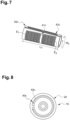
- a RFID tag 40a, 40b can be located between the outer wall 32 of the inner casing 30 and the inner wall 23 of the outer casing 20.
- said RFID tag 40a, 40b comprises a RFID chip 41a, 41b connected to at least one RFID antenna 42a, 42b extending substantially along a longitudinal axis A of the cover 10.
- the longitudinal axis A of the cover 10 is substantially parallel to the longitudinal axis A I of the medical injection device.
- the RFID tag 40a may be an UHF-RFID tag 40a comprising a RFID antenna 42a having two legs L1, L2.
- Leg L1 has an extremity E1
- leg L2 has an extremity E2.
- the RFID tag 40a is disposed between these two extremities E1, E2 of the legs L1, L2.
- the RFID chip 41a may be disposed at any place between the two extremities E1, E2, but at the extremities; or advantageously, the RFID chip 41a may be equidistant from both extremities E1, E2.
- the RFID tag 40a may be shaped as a square, a rectangle or a circle, typically the RFID tag 40a is shaped as a square or a rectangle.
- the RFID tag 40a extends on less than 100%, 100% being excluded, of the whole circumference of the outer wall 32 of the inner casing 30.
- the RFID tag 40a extends on less than 100%, 100% being excluded, of the whole circumference of the inner wall 23 of the outer casing 20.
- the RFID tag 40a When the RFID tag 40a is positioned between the outer wall 32 of the inner casing 30 and the inner wall 23 of the outer casing 20, the RFID tag 40a extends on less than 100%, 100% being excluded, of the whole circumference of the inner wall 23 of the outer casing 20. Preferably, two opposite sides of the RFID tag 40a are not in contact.
- the RFID tag 40a has a width W T extending over at least 40% of the circumference of the outer wall 32 of the inner casing 30. More preferably, the RFID tag 40a has a width W T extending between 40% and 100%, 100% being excluded, preferably between 50% and 100% and more preferably between 50 and 90%, or advantageously between 40% and 90% of the circumference of the outer wall 32 of the inner casing 30.
- the RFID tag extends on the length Lof the cover 10.
- the RFID tag 40a can have a length L T extending over at least 50%, typically at least 70% of a length L of the cover 10.
- the RFID tag 40a extends over the whole length L of the cover 10. This enables maximizing the exposition of the antenna to electromagnetic waves.
- the radius of curvature of the RFID tag 40a is comprised between the radius of curvature of the inner casing and the radius of curvature of the outer casing.
- the inventors have implemented a first RFID tag located between the outer wall of the inner casing as illustrated in Figure 3 .
- the RFID tag had a width W T extending over 63% of the circumference of the outer wall of the inner casing.
- the RFID tag had a length L T extending over 49% of a length L of the cover.
- the RFID tag had a read range of the data of 270mm maximum when the RFID tag was read on the side and from below.
- the inventors have implemented a second RFID tag located between the outer wall of the inner casing as illustrated in Figure 3 .
- the RFID tag had a width W T extending over 97% of the circumference of the outer wall of the inner casing.
- the RFID tag had a length L T extending over 74% of a length L of the cover.
- the RFID tag had a read range of the data of 430mm maximum when the RFID tag was read on the side and a read range of the data of 700mm maximum when the RFID tag was read from below.
- the cover comprising the second RFID tag offers a data transmission level significantly higher than the cover comprising the first RFID tag. Additionally, the location of the RFID tag between the outer wall of the inner casing and the inner wall of the outer casing does not affect the cover manufacturing process and has a low impact on the visual inspection.
- the RFID tag 40b is an UHF-RFID tag 40b comprising a RFID antenna 42b having two legs L1, L2.
- Leg L1 has an extremity E1
- leg L2 has an extremity E2.
- the RFID antenna 42b forms a loop
- the UHF-RFID chip 41b is located at the junction of the two legs L1, L2 and the loop of the RFID antenna 42b. The loop can be used to capture the near frequency field while the legs can be used to capture the far frequency field.
- the RFID tag 40b may be shaped as a square, a rectangle or a circle, typically the RFID tag 40b is shaped as a square or a rectangle.
- the RFID tag 40b extends on less than 100%, 100% being excluded, of the whole circumference of the outer wall 32 of the inner casing 30.
- the RFID tag 40b extends on less than 100%, 100% being excluded, of the whole circumference of the inner wall 23 of the outer casing 20.
- the RFID tag 40b When the RFID tag 40b is positioned between the outer wall 32 of the inner casing 30 and the inner wall 23 of the outer casing 20, the RFID tag 40b extends on less than 100%, 100% being excluded, of the whole circumference of the inner wall 23 of the outer casing 20. Preferably, two opposite sides of the RFID tag 40b are not in contact.
- the RFID tag 40b has a width W T extending over at least 40% of the circumference of the outer wall 32 of the inner casing 30. More preferably, the RFID tag 40b has a width W T extending between 40% and 100%, 100% being excluded, preferably between 50% and 100% and more preferably between 50 and 90%, or advantageously between 40% and 90% of the outer wall 32 of the inner casing 30.
- the RFID tag 40b extends on the length L of the cover 10.
- the RFID tag 40b can have a length L T extending over at least 50%, typically at least 70% of a length L of the cover 10.
- the RFID tag 40b extends over the whole length L of the cover 10. This enables maximizing the exposition of the antenna to electromagnetic waves.
- the RFID tag 40a, 40b is disposed between the outer wall 32 of the inner casing 30 and the inner wall 23 of the outer casing 20.
- Said RFID tag 40a, 40b may be in a form of a dry inlay or a wet inlay.
- the RFID tag 40a, 40b is bonded to the inner casing by adhesive bonding.
- the RFID tag 40a, 40b may be fixed to the inner casing by in-mold labelling, by adhesive bonding, by assembly, by co-molding or by over-molding.
- a RFID tag 40c can be located within the inner wall 23 of the outer casing 20, said UHF-RFID tag 40c comprising an UHF-RFID chip 41c connected to at least one UHF-RFID antenna 42c extending substantially along a longitudinal axis A of the cover 10.
- the RFID tag 40c is an UHF-RFID tag 40c comprising a RFID antenna 42c having two legs L1, L2.
- Leg L1 has an extremity E1
- leg L2 has an extremity E2.
- the RFID tag 40c may be shaped as a square, a rectangle or a circle, typically the RFID tag 40c is shaped as a square or a rectangle.
- the RFID tag 40c extends on less than 100%, 100% being excluded, of the whole circumference of the outer wall 32 of the inner casing 30.
- the RFID tag 40c extends on less than 100%, 100% being excluded, of the whole circumference of the inner wall 23 of the outer casing 20.
- the RFID tag 40c When the RFID tag 40c is positioned between the outer wall 32 of the inner casing 30 and the inner wall 23 of the outer casing 20, the RFID tag 40c extends on less than 100%, 100% being excluded, of the whole circumference of the inner wall 23 of the outer casing 20. Preferably, two opposite sides of the RFID tag 40c are not in contact.
- the RFID tag 40c have a width W T extending over at least 40% of the circumference of the outer wall 32 of the inner casing 30. More preferably, the RFID tag 40c have a width W T extending between 40% and 100%, 100% being excluded, advantageously between 50% and 100% and more preferably between 50 and 90%, or advantageously between 40% and 90% of the circumference of the outer wall 32 of the inner casing 30.
- the RFID tag extends on the length L of the cover 10.
- the RFID tag 40c can have a length L T extending over at least 50%, typically at least 70% of a length L of the cover 10.
- the RFID tag 40c extends over the whole length L of the cover 10. This enables maximizing the exposition of the antenna to electromagnetic waves.
- Figure 6 shows another view of the embodiment of Figure 5 .
- the RFID tag 40c in a form of wet inlay, is disposed within the inner wall 23 of the outer casing 20 by for example adhesive bonding.
- the two legs L1, L2 of the RFID antenna 42a, 42b, 42c are made of a plurality of square-shaped sinuso ⁇ ds having the same amplitude.
- the RFID tag 40a, 40b, 40c can have a longitudinal axis A parallel to the longitudinal axis A T of the cover device.
- Figure 7 illustrates the RFID tag 40c according to the embodiment shown in Figures 5 and 6 .
- Figure 8 illustrates the cross sectional view of the cover 10 comprising the RFID tag 40c comprising the antenna 42c and the chip 41c.
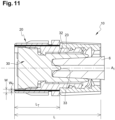
- Figure 9 shows a medical injection device 1 comprising a body 3 extending along a longitudinal axis A I .
- Said body 3 comprises a sidewall 11 and thus forms a reservoir, adapted to contain a medical composition 4 to be injected.
- the medical injection device 1 further comprises a hub portion 6 provided at its distal end 13 and extending along the axis A I from the distal end of the body 3.
- the hub portion 6 is partially hollow so as to form a channel (not illustrated) in fluidic communication with the body 3.
- an adaptator 50 including an internal thread 51 may be mounted around the hub portion 6 of the medical injection device in such a way that an annular space is created between the adaptor 50 and the hub portion 6.
- the adaptator may be connected to the medical injection device by any suitable connecting means.
- the cover 10 of the invention is intended to cover the hub portion 6 of the medical injection device.
- the medical injection device1 can also include, at its distal end, a distal shoulder which narrows with respect to the body 3.
- the medical injection device or syringe 1 shown in Figure 9 also includes a plunger rod 9 having a stopper 8 provided at an end thereof and a body flange 12.
- the stopper 8 is caused to slidably move in the body 3 along an inner surface of the sidewall 11 to cause the medical composition 4 to be expelled from the body 3 through the hub portion 6.
- the medical composition comprised in the medical injection device 1 may be for example, a liquid medicament, a drug or a pharmaceutical composition such as a vaccine.
- the cover 10 comprises an outer casing 20 and an inner casing 30.
- the cover 10 can be manufactured for example by injection molding.
- the outer casing 20 comprises a opened distal end and an opened proximal end
- the inner casing 30 comprises a closed distal end and an opened proximal end.
- the outer casing 20 comprises reinforcement means 10d increasing the rigidity of the cover 10 and at its proximal end, the outer casing 20 comprises an external thread 10a configured to be screwed into the internal thread 51 of the adaptator 50.
- the outer casing 20 comprises, at its proximal end, a proximal opening 10b configured to receive the inner casing 30, said inner casing 30 defining, at its proximal end, a cavity capable of receiving in a sealing way the hub portion 6.
- the inner casing 30 can comprise a nipple 33 configured to ensure a tight and sterile seal of the distal hub 6 on the medical injection device 1.
- Both the inner wall 23 of the outer casing 20 and the outer wall 32 of the inner casing 30 may have a circular cross section.
- the inner casing 30 is intended to cooperate with the hub portion 6 of the medical injection device 1 when the cover 10 is mounted on said hub portion 6.
- the inner casing 30 is intended to sealingly engage an outer surface of the hub portion 6 of the medical injection device 1.
- a RFID tag 40d can be located within the inner wall 23 of the outer casing 20, said RFID tag 40d comprising an RFID chip connected to at least one RFID antenna extending substantially along a longitudinal axis A I of the cover 10.
- the RFID tag 40d may be a LF-RFID tag, a HF-RFID tag or a UHF- RFIF tag, or a HF-NFC RFID tag.
- the RFID tag 40d is positioned within the outer wall 32 of the inner casing 30 or between the outer wall 32 of the inner casing 30 and the inner wall 23 of the outer casing 20.
- the RFID tag 40d may be shaped as a square, a rectangle or a circle, typically the RFID tag 40d is shaped as a square or a rectangle.
- the RFID tag 40d extends on less than 100%, 100% being excluded, of the whole circumference of the inner wall 23 of the outer casing 20.
- two opposite sides of the RFID tag 40d are not in contact.
- the RFID tag 40d have a width W T extending at least over 40%, 100% being excluded, of the circumference of the inner wall 23 of the outer casing 20.
- the RFID tag 40d has a width W T extending between 40% and 100%, preferably between 50% and 100% and more preferably between 50 and 90%, or advantageously between 40% and 90% of the inner wall 23 of the outer casing 20.
- the RFID tag extends on the length L of the cover 10.
- the RFID tag 40d can have a length L T extending over at least 50% of a length L of the cover 10. More preferably, the RFID tag 40d has a length L T extending over at least 70% of a length L of the cover 10.
- the RFID tag 40d extends over the whole length L of the cover 10. This enables maximizing the exposition of the antenna to electromagnetic waves of a reader.
- the radius of curvature of the RFID tag 40d is comprised between the radius of curvature of the inner casing and the radius of curvature of the outer casing.
- the RFID tag 40d may be in a form of a dry inlay or a wet inlay.
- the cover according to the present invention allows a highly effective individual identification of a medical injection device with no impact on visual inspection, with few or no risks of being removed or damaged, and with a limited impact on the manufacturing process.
Landscapes
- Health & Medical Sciences (AREA)
- Engineering & Computer Science (AREA)
- Life Sciences & Earth Sciences (AREA)
- Biomedical Technology (AREA)
- Veterinary Medicine (AREA)
- Animal Behavior & Ethology (AREA)
- Heart & Thoracic Surgery (AREA)
- Public Health (AREA)
- General Health & Medical Sciences (AREA)
- Vascular Medicine (AREA)
- Physics & Mathematics (AREA)
- Anesthesiology (AREA)
- Hematology (AREA)
- Microelectronics & Electronic Packaging (AREA)
- Theoretical Computer Science (AREA)
- General Physics & Mathematics (AREA)
- Surgery (AREA)
- Computer Hardware Design (AREA)
- Pathology (AREA)
- Medical Informatics (AREA)
- Molecular Biology (AREA)
- Oral & Maxillofacial Surgery (AREA)
- Nuclear Medicine, Radiotherapy & Molecular Imaging (AREA)
- Electromagnetism (AREA)
- Infusion, Injection, And Reservoir Apparatuses (AREA)
- Details Of Aerials (AREA)
- Computer Networks & Wireless Communication (AREA)
Applications Claiming Priority (3)
| Application Number | Priority Date | Filing Date | Title |
|---|---|---|---|
| EP20175263 | 2020-05-18 | ||
| PCT/EP2021/059839 WO2021233613A1 (en) | 2020-05-18 | 2021-04-15 | A cover for a medical injection device comprising a radio frequency identification (rfid) tag |
| EP21717921.7A EP4154178B1 (de) | 2020-05-18 | 2021-04-15 | Starrer nadelschutz mit rfid-uhf-etikett |
Related Parent Applications (2)
| Application Number | Title | Priority Date | Filing Date |
|---|---|---|---|
| EP21717921.7A Division-Into EP4154178B1 (de) | 2020-05-18 | 2021-04-15 | Starrer nadelschutz mit rfid-uhf-etikett |
| EP21717921.7A Division EP4154178B1 (de) | 2020-05-18 | 2021-04-15 | Starrer nadelschutz mit rfid-uhf-etikett |
Publications (2)
| Publication Number | Publication Date |
|---|---|
| EP4431136A2 true EP4431136A2 (de) | 2024-09-18 |
| EP4431136A3 EP4431136A3 (de) | 2024-12-18 |
Family
ID=70740551
Family Applications (2)
| Application Number | Title | Priority Date | Filing Date |
|---|---|---|---|
| EP24192752.4A Pending EP4431136A3 (de) | 2020-05-18 | 2021-04-15 | Abdeckung für eine medizinische injektionsvorrichtung mit einem rfid-etikett |
| EP21717921.7A Active EP4154178B1 (de) | 2020-05-18 | 2021-04-15 | Starrer nadelschutz mit rfid-uhf-etikett |
Family Applications After (1)
| Application Number | Title | Priority Date | Filing Date |
|---|---|---|---|
| EP21717921.7A Active EP4154178B1 (de) | 2020-05-18 | 2021-04-15 | Starrer nadelschutz mit rfid-uhf-etikett |
Country Status (11)
| Country | Link |
|---|---|
| US (1) | US12533475B2 (de) |
| EP (2) | EP4431136A3 (de) |
| JP (1) | JP7738577B2 (de) |
| KR (1) | KR20230012011A (de) |
| CN (1) | CN115699015B (de) |
| AU (1) | AU2021274781A1 (de) |
| BR (1) | BR112022023343A2 (de) |
| CA (1) | CA3178517A1 (de) |
| ES (1) | ES2993222T3 (de) |
| MX (1) | MX2022014434A (de) |
| WO (1) | WO2021233613A1 (de) |
Families Citing this family (6)
| Publication number | Priority date | Publication date | Assignee | Title |
|---|---|---|---|---|
| US11811989B2 (en) * | 2012-04-25 | 2023-11-07 | Brother Kogyo Kabushiki Kaisha | Image forming apparatus including antenna in cover |
| EP4275146A4 (de) | 2021-01-10 | 2025-02-19 | Kapoor, Puneet | Artikel mit eingebetteten rfid-etiketten und herstellungsverfahren dafür |
| JP2025503777A (ja) * | 2022-01-21 | 2025-02-04 | ベクトン ディキンソン フランス | Rfidタグ及び折り畳み式アンテナを有するシリンジ剛性針シールド |
| CN121263221A (zh) * | 2023-05-30 | 2026-01-02 | 贝克顿迪金森法国公司 | 具有集成rfid和帽端扭矩传递特征的共模制刚性帽 |
| EP4470584A1 (de) * | 2023-05-31 | 2024-12-04 | Becton, Dickinson and Company | Abdeckung für eine medizinische injektionsvorrichtung mit optimal ausgerichtetem rfid-etikett |
| EP4603123A1 (de) * | 2024-02-13 | 2025-08-20 | Becton Dickinson France | Nadelschutz mit einzigartigen identifizierungsinformationen |
Citations (2)
| Publication number | Priority date | Publication date | Assignee | Title |
|---|---|---|---|---|
| WO2017157784A1 (en) | 2016-03-16 | 2017-09-21 | Vesdo Inc. | A receptacle comprising machine-readable unique identifier codes and methods for their application and reading out |
| US20190217018A1 (en) | 2016-07-11 | 2019-07-18 | Carebay Europe Ltd | Rfid tag enabled shield assembly |
Family Cites Families (15)
| Publication number | Priority date | Publication date | Assignee | Title |
|---|---|---|---|---|
| US7887559B2 (en) * | 2002-08-08 | 2011-02-15 | Stryker Corporation | Surgical cutting accessory with encapsulated RFID chip |
| WO2010022157A1 (en) * | 2008-08-19 | 2010-02-25 | James Joseph Pedicano | Stretchable wristband with rfid chip |
| DE102011116399A1 (de) * | 2011-10-19 | 2013-04-25 | Id-Systec Gmbh | In-Mould-Etikett |
| DE102011120859A1 (de) | 2011-12-13 | 2013-06-13 | Felix Schoeller Supply Chain Technologies Gmbh & Co. Kg | Transponderanordnung für die Integration in einem Objekt |
| EP2656865A1 (de) | 2012-04-24 | 2013-10-30 | Sanofi-Aventis Deutschland GmbH | Spritzenträger mit Nadelschutzhülse und Datenspeicher zur Verwendung in medizinischem Auto-Injektor |
| US9821123B2 (en) * | 2014-01-27 | 2017-11-21 | Ucb Biopharma Sprl | Auto-injector |
| ES3028296T3 (en) * | 2016-07-11 | 2025-06-18 | Shl Medical Ag | Rfid tag enabled needle shield |
| WO2018015783A1 (en) * | 2016-07-18 | 2018-01-25 | Assa Abloy Ab | A tubular shaped tag structure |
| EP3476417A1 (de) * | 2017-10-31 | 2019-05-01 | Tecpharma Licensing AG | Überwachung von wegwerfbaren injektionsvorrichtungen |
| CN108257658A (zh) * | 2018-01-29 | 2018-07-06 | 河南泰合医疗器械制造有限公司 | 一种带芯片的医用安全信息针头 |
| JP2019192084A (ja) * | 2018-04-27 | 2019-10-31 | パナソニックIpマネジメント株式会社 | Rfタグ |
| IL278443B2 (en) * | 2018-05-04 | 2025-07-01 | Bigfoot Biomedical Inc | Therapy devices, methods, and systems including a piston-style detector |
| JP7155751B2 (ja) * | 2018-08-23 | 2022-10-19 | 大日本印刷株式会社 | Rfタグラベル |
| MX2021015932A (es) | 2019-06-28 | 2022-07-27 | Becton Dickinson France | Una brida de plastico para un recipiente medico, un recipiente medico que incluye esta brida de plastico y un metodo para fabricar este recipiente medico. |
| RU197124U1 (ru) | 2019-12-20 | 2020-04-02 | Общество с ограниченной ответственностью "Научно-производственный Инновационный внедренческий центр" | Одноразовый картридж для ингалятора |
-
2021
- 2021-04-15 KR KR1020227043847A patent/KR20230012011A/ko active Pending
- 2021-04-15 CN CN202180043159.XA patent/CN115699015B/zh active Active
- 2021-04-15 BR BR112022023343A patent/BR112022023343A2/pt unknown
- 2021-04-15 AU AU2021274781A patent/AU2021274781A1/en active Pending
- 2021-04-15 ES ES21717921T patent/ES2993222T3/es active Active
- 2021-04-15 US US17/926,049 patent/US12533475B2/en active Active
- 2021-04-15 EP EP24192752.4A patent/EP4431136A3/de active Pending
- 2021-04-15 EP EP21717921.7A patent/EP4154178B1/de active Active
- 2021-04-15 CA CA3178517A patent/CA3178517A1/en active Pending
- 2021-04-15 WO PCT/EP2021/059839 patent/WO2021233613A1/en not_active Ceased
- 2021-04-15 MX MX2022014434A patent/MX2022014434A/es unknown
- 2021-04-15 JP JP2022570489A patent/JP7738577B2/ja active Active
Patent Citations (2)
| Publication number | Priority date | Publication date | Assignee | Title |
|---|---|---|---|---|
| WO2017157784A1 (en) | 2016-03-16 | 2017-09-21 | Vesdo Inc. | A receptacle comprising machine-readable unique identifier codes and methods for their application and reading out |
| US20190217018A1 (en) | 2016-07-11 | 2019-07-18 | Carebay Europe Ltd | Rfid tag enabled shield assembly |
Also Published As
| Publication number | Publication date |
|---|---|
| JP2023526845A (ja) | 2023-06-23 |
| EP4154178C0 (de) | 2024-10-30 |
| EP4154178B1 (de) | 2024-10-30 |
| JP7738577B2 (ja) | 2025-09-12 |
| CN115699015B (zh) | 2026-03-03 |
| CA3178517A1 (en) | 2021-11-25 |
| MX2022014434A (es) | 2022-12-08 |
| WO2021233613A1 (en) | 2021-11-25 |
| US12533475B2 (en) | 2026-01-27 |
| AU2021274781A1 (en) | 2022-12-15 |
| KR20230012011A (ko) | 2023-01-25 |
| EP4431136A3 (de) | 2024-12-18 |
| EP4154178A1 (de) | 2023-03-29 |
| BR112022023343A2 (pt) | 2022-12-20 |
| ES2993222T3 (en) | 2024-12-26 |
| US20230181841A1 (en) | 2023-06-15 |
| CN115699015A (zh) | 2023-02-03 |
Similar Documents
| Publication | Publication Date | Title |
|---|---|---|
| EP4154178B1 (de) | Starrer nadelschutz mit rfid-uhf-etikett | |
| EP4154179B1 (de) | Ringförmiges rfid-etikett für eine spritzenspitzenkappe | |
| KR20240012493A (ko) | 주사기용 바늘 차폐부 조립체 | |
| US12131210B2 (en) | Medical container comprising a rfid tag for remote identification of said medical container | |
| RU2827670C1 (ru) | Крышка для медицинского инъекционного устройства, способ ее изготовления и медицинское инъекционное устройство | |
| US20250127990A1 (en) | Medical Injection Device and Method for Assembling This Injection Device | |
| EP4094791A1 (de) | Medizinisches vorrichtung mit rfid-tag, der direkt auf einen teil dieser medizinischen vorrichtung gedruckt ist | |
| WO2024249055A1 (en) | Medical injection device cover with optimally oriented rfid tag |
Legal Events
| Date | Code | Title | Description |
|---|---|---|---|
| PUAI | Public reference made under article 153(3) epc to a published international application that has entered the european phase |
Free format text: ORIGINAL CODE: 0009012 |
|
| STAA | Information on the status of an ep patent application or granted ep patent |
Free format text: STATUS: THE APPLICATION HAS BEEN PUBLISHED |
|
| AC | Divisional application: reference to earlier application |
Ref document number: 4154178 Country of ref document: EP Kind code of ref document: P |
|
| AK | Designated contracting states |
Kind code of ref document: A2 Designated state(s): AL AT BE BG CH CY CZ DE DK EE ES FI FR GB GR HR HU IE IS IT LI LT LU LV MC MK MT NL NO PL PT RO RS SE SI SK SM TR |
|
| REG | Reference to a national code |
Ref country code: DE Ref legal event code: R079 Free format text: PREVIOUS MAIN CLASS: A61M0005320000 Ipc: G06K0019077000 Ref country code: DE Ref legal event code: R079 Ref document number: 602021051954 Country of ref document: DE Free format text: PREVIOUS MAIN CLASS: A61M0005320000 Ipc: G06K0019077000 |
|
| PUAL | Search report despatched |
Free format text: ORIGINAL CODE: 0009013 |
|
| AK | Designated contracting states |
Kind code of ref document: A3 Designated state(s): AL AT BE BG CH CY CZ DE DK EE ES FI FR GB GR HR HU IE IS IT LI LT LU LV MC MK MT NL NO PL PT RO RS SE SI SK SM TR |
|
| RIC1 | Information provided on ipc code assigned before grant |
Ipc: A61M 5/32 20060101ALI20241112BHEP Ipc: G06K 19/077 20060101AFI20241112BHEP |
|
| STAA | Information on the status of an ep patent application or granted ep patent |
Free format text: STATUS: REQUEST FOR EXAMINATION WAS MADE |
|
| 17P | Request for examination filed |
Effective date: 20250612 |
|
| GRAP | Despatch of communication of intention to grant a patent |
Free format text: ORIGINAL CODE: EPIDOSNIGR1 |
|
| STAA | Information on the status of an ep patent application or granted ep patent |
Free format text: STATUS: GRANT OF PATENT IS INTENDED |
|
| GRAS | Grant fee paid |
Free format text: ORIGINAL CODE: EPIDOSNIGR3 |
|
| GRAA | (expected) grant |
Free format text: ORIGINAL CODE: 0009210 |
|
| STAA | Information on the status of an ep patent application or granted ep patent |
Free format text: STATUS: THE PATENT HAS BEEN GRANTED |
|
| INTG | Intention to grant announced |
Effective date: 20260212 |