EP4429100A1 - Micro inverter - Google Patents
Micro inverter Download PDFInfo
- Publication number
- EP4429100A1 EP4429100A1 EP22929675.1A EP22929675A EP4429100A1 EP 4429100 A1 EP4429100 A1 EP 4429100A1 EP 22929675 A EP22929675 A EP 22929675A EP 4429100 A1 EP4429100 A1 EP 4429100A1
- Authority
- EP
- European Patent Office
- Prior art keywords
- micro inverter
- conversion
- bridge arm
- transformer
- inductor
- Prior art date
- Legal status (The legal status is an assumption and is not a legal conclusion. Google has not performed a legal analysis and makes no representation as to the accuracy of the status listed.)
- Pending
Links
Images




Classifications
-
- H—ELECTRICITY
- H02—GENERATION; CONVERSION OR DISTRIBUTION OF ELECTRIC POWER
- H02M—APPARATUS FOR CONVERSION BETWEEN AC AND AC, BETWEEN AC AND DC, OR BETWEEN DC AND DC, AND FOR USE WITH MAINS OR SIMILAR POWER SUPPLY SYSTEMS; CONVERSION OF DC OR AC INPUT POWER INTO SURGE OUTPUT POWER; CONTROL OR REGULATION THEREOF
- H02M7/00—Conversion of AC power input into DC power output; Conversion of DC power input into AC power output
- H02M7/42—Conversion of DC power input into AC power output without possibility of reversal
- H02M7/44—Conversion of DC power input into AC power output without possibility of reversal by static converters
- H02M7/48—Conversion of DC power input into AC power output without possibility of reversal by static converters using discharge tubes with control electrode or semiconductor devices with control electrode
- H02M7/53—Conversion of DC power input into AC power output without possibility of reversal by static converters using discharge tubes with control electrode or semiconductor devices with control electrode using devices of a triode or transistor type requiring continuous application of a control signal
- H02M7/537—Conversion of DC power input into AC power output without possibility of reversal by static converters using discharge tubes with control electrode or semiconductor devices with control electrode using devices of a triode or transistor type requiring continuous application of a control signal using semiconductor devices only, e.g. single switched pulse inverters
- H02M7/5387—Conversion of DC power input into AC power output without possibility of reversal by static converters using discharge tubes with control electrode or semiconductor devices with control electrode using devices of a triode or transistor type requiring continuous application of a control signal using semiconductor devices only, e.g. single switched pulse inverters in a bridge configuration
- H02M7/53871—Conversion of DC power input into AC power output without possibility of reversal by static converters using discharge tubes with control electrode or semiconductor devices with control electrode using devices of a triode or transistor type requiring continuous application of a control signal using semiconductor devices only, e.g. single switched pulse inverters in a bridge configuration with automatic control of output voltage or current
-
- H—ELECTRICITY
- H02—GENERATION; CONVERSION OR DISTRIBUTION OF ELECTRIC POWER
- H02J—ELECTRIC POWER NETWORKS; CIRCUIT ARRANGEMENTS OR SYSTEMS FOR SUPPLYING OR DISTRIBUTING ELECTRIC POWER; SYSTEMS FOR STORING ELECTRIC ENERGY
- H02J3/00—Circuit arrangements for AC mains or AC distribution networks
- H02J3/38—Arrangements for feeding a single network from two or more generators or sources in parallel; Arrangements for feeding already energised networks from additional generators or sources in parallel
- H02J3/381—Dispersed generators
-
- H—ELECTRICITY
- H02—GENERATION; CONVERSION OR DISTRIBUTION OF ELECTRIC POWER
- H02M—APPARATUS FOR CONVERSION BETWEEN AC AND AC, BETWEEN AC AND DC, OR BETWEEN DC AND DC, AND FOR USE WITH MAINS OR SIMILAR POWER SUPPLY SYSTEMS; CONVERSION OF DC OR AC INPUT POWER INTO SURGE OUTPUT POWER; CONTROL OR REGULATION THEREOF
- H02M1/00—Details of apparatus for conversion
- H02M1/0064—Magnetic structures combining different functions, e.g. storage, filtering or transformation
-
- H—ELECTRICITY
- H02—GENERATION; CONVERSION OR DISTRIBUTION OF ELECTRIC POWER
- H02M—APPARATUS FOR CONVERSION BETWEEN AC AND AC, BETWEEN AC AND DC, OR BETWEEN DC AND DC, AND FOR USE WITH MAINS OR SIMILAR POWER SUPPLY SYSTEMS; CONVERSION OF DC OR AC INPUT POWER INTO SURGE OUTPUT POWER; CONTROL OR REGULATION THEREOF
- H02M1/00—Details of apparatus for conversion
- H02M1/0083—Converters characterised by their input or output configuration
-
- H—ELECTRICITY
- H02—GENERATION; CONVERSION OR DISTRIBUTION OF ELECTRIC POWER
- H02M—APPARATUS FOR CONVERSION BETWEEN AC AND AC, BETWEEN AC AND DC, OR BETWEEN DC AND DC, AND FOR USE WITH MAINS OR SIMILAR POWER SUPPLY SYSTEMS; CONVERSION OF DC OR AC INPUT POWER INTO SURGE OUTPUT POWER; CONTROL OR REGULATION THEREOF
- H02M1/00—Details of apparatus for conversion
- H02M1/32—Means for protecting converters other than automatic disconnection
-
- H—ELECTRICITY
- H02—GENERATION; CONVERSION OR DISTRIBUTION OF ELECTRIC POWER
- H02M—APPARATUS FOR CONVERSION BETWEEN AC AND AC, BETWEEN AC AND DC, OR BETWEEN DC AND DC, AND FOR USE WITH MAINS OR SIMILAR POWER SUPPLY SYSTEMS; CONVERSION OF DC OR AC INPUT POWER INTO SURGE OUTPUT POWER; CONTROL OR REGULATION THEREOF
- H02M7/00—Conversion of AC power input into DC power output; Conversion of DC power input into AC power output
- H02M7/42—Conversion of DC power input into AC power output without possibility of reversal
- H02M7/44—Conversion of DC power input into AC power output without possibility of reversal by static converters
- H02M7/48—Conversion of DC power input into AC power output without possibility of reversal by static converters using discharge tubes with control electrode or semiconductor devices with control electrode
-
- H—ELECTRICITY
- H02—GENERATION; CONVERSION OR DISTRIBUTION OF ELECTRIC POWER
- H02M—APPARATUS FOR CONVERSION BETWEEN AC AND AC, BETWEEN AC AND DC, OR BETWEEN DC AND DC, AND FOR USE WITH MAINS OR SIMILAR POWER SUPPLY SYSTEMS; CONVERSION OF DC OR AC INPUT POWER INTO SURGE OUTPUT POWER; CONTROL OR REGULATION THEREOF
- H02M7/00—Conversion of AC power input into DC power output; Conversion of DC power input into AC power output
- H02M7/42—Conversion of DC power input into AC power output without possibility of reversal
- H02M7/44—Conversion of DC power input into AC power output without possibility of reversal by static converters
- H02M7/48—Conversion of DC power input into AC power output without possibility of reversal by static converters using discharge tubes with control electrode or semiconductor devices with control electrode
- H02M7/4807—Conversion of DC power input into AC power output without possibility of reversal by static converters using discharge tubes with control electrode or semiconductor devices with control electrode having a high frequency intermediate AC stage
-
- H—ELECTRICITY
- H02—GENERATION; CONVERSION OR DISTRIBUTION OF ELECTRIC POWER
- H02J—ELECTRIC POWER NETWORKS; CIRCUIT ARRANGEMENTS OR SYSTEMS FOR SUPPLYING OR DISTRIBUTING ELECTRIC POWER; SYSTEMS FOR STORING ELECTRIC ENERGY
- H02J2101/00—Supply or distribution of decentralised, dispersed or local electric power generation
- H02J2101/20—Dispersed power generation using renewable energy sources
- H02J2101/22—Solar energy
- H02J2101/24—Photovoltaics
- H02J2101/25—Photovoltaics involving maximum power point tracking control for photovoltaic sources
-
- H—ELECTRICITY
- H02—GENERATION; CONVERSION OR DISTRIBUTION OF ELECTRIC POWER
- H02M—APPARATUS FOR CONVERSION BETWEEN AC AND AC, BETWEEN AC AND DC, OR BETWEEN DC AND DC, AND FOR USE WITH MAINS OR SIMILAR POWER SUPPLY SYSTEMS; CONVERSION OF DC OR AC INPUT POWER INTO SURGE OUTPUT POWER; CONTROL OR REGULATION THEREOF
- H02M1/00—Details of apparatus for conversion
- H02M1/0067—Converter structures employing plural converter units, other than for parallel operation of the units on a single load
- H02M1/0077—Plural converter units whose outputs are connected in series
-
- H—ELECTRICITY
- H02—GENERATION; CONVERSION OR DISTRIBUTION OF ELECTRIC POWER
- H02M—APPARATUS FOR CONVERSION BETWEEN AC AND AC, BETWEEN AC AND DC, OR BETWEEN DC AND DC, AND FOR USE WITH MAINS OR SIMILAR POWER SUPPLY SYSTEMS; CONVERSION OF DC OR AC INPUT POWER INTO SURGE OUTPUT POWER; CONTROL OR REGULATION THEREOF
- H02M7/00—Conversion of AC power input into DC power output; Conversion of DC power input into AC power output
- H02M7/42—Conversion of DC power input into AC power output without possibility of reversal
- H02M7/44—Conversion of DC power input into AC power output without possibility of reversal by static converters
- H02M7/48—Conversion of DC power input into AC power output without possibility of reversal by static converters using discharge tubes with control electrode or semiconductor devices with control electrode
- H02M7/483—Converters with outputs that each can have more than two voltages levels
- H02M7/49—Combination of the output voltage waveforms of a plurality of converters
-
- Y—GENERAL TAGGING OF NEW TECHNOLOGICAL DEVELOPMENTS; GENERAL TAGGING OF CROSS-SECTIONAL TECHNOLOGIES SPANNING OVER SEVERAL SECTIONS OF THE IPC; TECHNICAL SUBJECTS COVERED BY FORMER USPC CROSS-REFERENCE ART COLLECTIONS [XRACs] AND DIGESTS
- Y02—TECHNOLOGIES OR APPLICATIONS FOR MITIGATION OR ADAPTATION AGAINST CLIMATE CHANGE
- Y02E—REDUCTION OF GREENHOUSE GAS [GHG] EMISSIONS, RELATED TO ENERGY GENERATION, TRANSMISSION OR DISTRIBUTION
- Y02E10/00—Energy generation through renewable energy sources
- Y02E10/50—Photovoltaic [PV] energy
- Y02E10/56—Power conversion systems, e.g. maximum power point trackers
Definitions
- the present disclosure relates to the technical field of power electronics, and in particular to a micro inverter.
- micro inverter can perform maximum power point tracking (MPPT) in a module-level, power generation of photovoltaic modules will not be affected by each other. In addition, no short board effect will be caused among photovoltaic modules connected in series, so that partial occlusion and orientation inconsistency do not affect the power generation of a whole string of modules. Moreover, operation and maintenance may be implemented in a module-level with the micro inverter. Therefore, the micro inverter has received a widespread attention.
- MPPT maximum power point tracking
- a one-drive-two flyback micro inverter is provided according to the conventional technology.
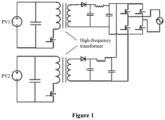
- the topological structure of the flyback micro inverter is shown in Figure 1 , the flyback micro inverter can implement inversion and output for two photovoltaic modules PV1 and PV2, to improve a power density of the system.
- the solution shown in Figure 1 requires multiple high-frequency transformers, resulting in a large overall volume and a high cost.
- the solution relates to a two-stage conversion structure, where a flyback converter is used for increasing voltage in a first conversion stage, and an H-bridge is used for inversion in a second conversion stage. A conversion efficiency of this two-stage conversion structure is low.
- a micro inverter is provided according to the present disclosure, to reduce a volume and a cost, and improve conversion efficiency.
- the micro inverter includes a control unit, a transformer, a secondary-side bridge arm and N conversion branches, where N is an integer greater than one.
- Each of input terminals of the conversion branches serves as an input terminal of the micro inverter and is connected to a corresponding direct-current power supply or load.
- Output terminals of the conversion branches are cascaded, and two terminals of the cascaded conversion branches are connected to an input terminal of the secondary-side bridge arm through the transformer.
- An output terminal of the secondary-side bridge arm serves as an output terminal of the micro inverter.
- the secondary-side bridge arm and the N conversion branches are controlled via the control unit.
- the transformer is a high-frequency dual-winding transformer.
- a primary-side winding of the transformer is connected to the two terminals of the cascaded conversion branches through a first inductor; and/or a secondary-side winding of the transformer is connected to the input terminal of the secondary-side bridge arm through a second inductor.
- the first inductor is independent of the primary-side winding, or the first inductor is a primary-side leakage inductor integrated in the transformer; and the second inductor is independent of the secondary-side winding, or the second inductor is a secondary-side leakage inductor integrated in the transformer.
- the secondary-side bridge arm includes two bidirectional switches and two output-side capacitors.
- the two bidirectional switches are connected in series to form a branch
- the two output-side capacitors are connected in series to form another branch
- the two branches are connected in parallel to two ends of the output terminal of the secondary-side bridge arm.
- a connection point between the two bidirectional switches, and a connection point between the two output-side capacitors respectively serve as two ends of the input terminal of the secondary-side bridge arm.
- each of the bidirectional switches includes two switching transistors connected in reverse series.
- each of the conversion branches includes an H-bridge circuit and an input-side capacitor. Two terminals of the input-side capacitor and two ends of the H-bridge circuit at a direct-current side are connected to the two ends of the input terminal of the conversion branch; and the two terminals of the H-bridge circuit at an alternating-current side serve as two ends of the output terminals of the conversion branch.
- control unit is configured to independently control the H-bridge circuits.
- phase-shift angle between the H-bridge circuit and the secondary-side bridge arm in a case that a phase-shift angle between the H-bridge circuit and the secondary-side bridge arm is greater than zero, power in the H-bridge circuit is transmitted from the direct-current side to the alternating-current side; and in a case that the phase-shift angle between the H-bridge circuit and the secondary-side bridge arm is less than zero, the power in the H-bridge circuit is transmitted from the alternating-current side to the direct-current side.
- control unit in a case that an input terminal of one of the N conversion branches is connected with no device, the control unit is configured to control two ends of the output terminal of the conversion branch to be short-circuited.
- control unit in order to control the two ends of the output terminal of the conversion branch to be short-circuited, is further configured to control at least two of four switching transistors in the H-bridge circuit to be turned on.
- each of input terminals of the micro inverter is connected to a photovoltaic module or an energy storage device.
- the micro inverter further includes: a grid-side filter arranged between the output terminal of the secondary-side bridge arm and the output terminal of the micro inverter.
- N conversion branches in the main circuit are cascaded, to share a same transformer to be connected to the secondary-side bridge arm, avoiding the arrangement of N transformers in the conventional technology.
- the N cascaded conversion branches can implement decoupling, so that it is unnecessary to provide a device for decoupling for each branch, thereby reducing the volume and the cost.
- each direct-current power supply or load can be connected to an alternating-current grid via only one-stage conversion, compared with the two-stage conversion structure in the conventional technology, the loss in the conversion process is reduced and the conversion efficiency is improved according to the present disclosure.
- a micro inverter is provided according to the present disclosure, to reduce a volume and a cost, and improve conversion efficiency.
- the micro inverter includes a control unit (not shown in Figure 2 ), a transformer 102, a secondary-side bridge arm 103 and N conversion branches 101, where N is an integer greater than one.
- Each of input terminals of the N conversion branches 101 serves as an input terminal of the micro inverter and is connected to a corresponding direct-current power supply or a load.
- each of the input terminals of the N conversion branches 101 may be connected to a direct-current power supply such as a photovoltaic module, or an energy storage device, such as device which can serve as either a direct-current power supply or a load, e.g. a battery.
- a direct-current power supply such as a photovoltaic module
- an energy storage device such as device which can serve as either a direct-current power supply or a load, e.g. a battery.
- the battery in a case that the battery is in a discharge state, the battery functions as a direct-current power supply, and in a case that the battery is in a charge state, the battery functions as a load. That is, the input and output terminals of the micro inverter are only explained by taking a state of being connected to the direct-current power supply as an example, and
- Output terminals of conversion branches 101 are cascaded, and two terminals of the cascaded conversion branches are connected to an input terminal of the secondary-side bridge arm 103 through the transformer 102.
- the transformer 102 may be a high-frequency double-winding transformer.
- the transformer 102 may include: an iron core, a primary-side winding and a secondary-side winding.
- the primary-side winding of the transformer 102 is connected to the two terminals of the cascaded conversion branches 101 through a first inductor L1 (as shown in Figure 3a ).
- a secondary-side winding of the transformer 102 is connected to an input terminal of the secondary-side bridge arm 103 through a second inductor L2 (as shown in Figure 2 and Figure 3b ).
- the primary-side winding of the transformer 102 is connected to the two terminals of the cascaded conversion branches 101 through the first inductor L1
- the secondary-side winding of the transformer 102 is connected to the input terminal of the secondary-side bridge arm 103 through the second inductor L2 (as shown in Figure 3c ).
- the first inductor L1 and the second inductor L2 may be independent inductors, that is, being independently arranged at a side of the transformer 102.
- the second inductor L2 may be integrated in the transformer 102 in a form of a secondary-side leakage inductor
- the first inductor L1 may be integrated in the transformer 102 in a form of a primary-side leakage inductor, which depends on the specific application environment and fall within the protection scope of the present disclosure.
- the output terminal of the secondary-side bridge arm 103 serves as an output terminal of the micro inverter.
- the output terminal of the micro inverter may be connected to the power grid through an external filter.
- the micro inverter may be provided with a grid-side filter 104 arranged between the output terminal of the secondary-side bridge arm 103 and the output terminal of the micro inverter.
- the grid-side filter 104 may be an LC filter, but not limited to this, which is within the protection scope of the present disclosure.
- Direct-current power from each direct-current power supply is converted to an alternating-current power through a single-stage conversion by a corresponding conversion branch 101.
- Alternating-current power from the output terminals of the cascaded conversion branches 101, that is, the alternating-current side, is inputted to the transformer 102 for voltage increasing and isolation, then a second inductor L2 at the secondary side changes the phase of the power of the secondary-side winding and transmits the power to the input terminal of the secondary-side bridge arm 103.
- the secondary-side bridge arm 103 adjusts the power to an alternating-current power for grid connection.
- each of the input terminal is connected to a load
- the direction of the current is opposite, and the voltage of the transformer 102 at the primary side is shared among the cascaded conversion branches 101, and each of the conversion branch 101 performs power conversion to supply power to the corresponding load.
- the micro inverter provided in the embodiment performs energy coupling by multiple cascaded conversion branches 101, and it is unnecessary to increase the quantity of the primary-side winding in the transformer 102 in a case that the quantity of input ports is increased.
- the cascaded structure may further be used to implement the independent control of direct-current-side power of the conversion branches 101, that is, the power magnitude and current direction of each conversion branch 101 may be controlled independently, so that the decoupling among the multiple inputs can be implemented, avoiding the arrangement of an inductor for each of the multiple inputs in the conventional technology. Therefore, compared with the above solution with multiple primary-side windings, in this embodiment, the quantity of windings and inductors are reduced, thereby reducing the volume of the transformer, thus reducing the system cost.
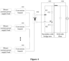
- Figure 4 shows an example of a topological structure of the micro-inverter.
- a secondary-side bridge arm 103 includes: two bidirectional switches K1 and K2, and two output-side capacitors C2 and C3.
- the two bidirectional switches K1 and K2 are connected in series to form a branch, the two output-side capacitors C2 and C3 are connected in series to form another branch, and the two branches are connected in parallel to two ends of the output terminal of the secondary-side bridge arm 103.
- Figure 4 shows an example in which a leakage inductor is used, and an inductor independent of the transformer 102 is not shown in the drawings.
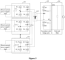
- each of the bidirectional switches K1 and K2 may include two switching transistors connected in reverse series.
- the bidirectional switching transistor K1 includes two N-metal-oxide-semiconductor (NMOS) transistors S5 and S6 sharing a common source
- the bidirectional switch K2 includes two NMOS transistors S7 and S8 sharing a common source.
- NMOS N-metal-oxide-semiconductor
- IGBTs insulated gate bipolar transistors
- other switching transistors may be used to implement bidirectional switching, which is not limited herein, may be determined according to the application environment, and fall within the protection scope of the present disclosure.
- the conversion branch 101 includes: a H-bridge circuit (including S1_1, S2_1, S3_1 and S4_1, or S1_2, S2_2, S3_2 and S4_2, or S1_N, S2_N, S3_N and S4_N as shown in Figure 5 ) and a input-side capacitor (C1_1, C1_2 or C1_N as shown in Figure 5 ).
- a H-bridge circuit including S1_1, S2_1, S3_1 and S4_1, or S1_2, S2_2, S3_2 and S4_2, or S1_N, S2_N, S3_N and S4_N as shown in Figure 5
- C1_1, C1_2 or C1_N as shown in Figure 5
- Two terminals of the input-side capacitor and the two ends of the H-bridge circuit at the direct-current side are connected to the two ends of the input terminal of the conversion branch 101.
- two terminals of the input-side capacitor C1_1 and two ends of the H-bridge circuit (including S1_1, S2_1, S3_1 and S4_1) at the direct-current side are connected to the two ends of the input terminal of the first conversion branch 101.
- two terminals of the input-side capacitor C1_2 and the two ends of the H-bridge circuit (including S1_2, S2_2, S3_2 and S4_2) at the direct-current side are connected to the two ends of the input terminal of the second conversion branch 101.
- N-th conversion branch 101 two terminals of the input-side capacitor C1_N and the two ends of the H-bridge circuit (including S1_N, S2_N, S3_N and S4_N) at the direct-current side are connected to the two ends of the input terminal of the N-th conversion branch 101.
- the two terminals (A1 and A1', or A2 and A2', or AN and AN' shown in Figure 5 ) of the H-bridge circuit at the alternating-current side serve as two ends of output terminal of the conversion branch 101.
- transformer 102 can be connected to multiple direct-current power supplies or loads through the cascaded N H-bridge circuits, and secondary-side bridge arm 103 adopts the bidirectional switch to implement a grid connection.
- Figure 6 shows a topological structure of a micro inverter with a single-stage conversion and two-input.
- a main circuit of the micro inverter adopts a dual active bridge (DAB) and a bidirectional switch, and implements a conversion between the direct-current power and alternating-current power through single-stage conversion, which improves the efficiency of grid connection.
- DAB dual active bridge
- a direct-current power is inputted from a first photovoltaic module, where a direct-current voltage is converted into a pulsating voltage through the high-frequency switches (including S1_1, S2_1, S3_1 and S4_1) of the H-bridge circuit, and a same conversion process is performed on the direct-current power inputted from a second photovoltaic module. Then, as output terminals of the two alternating-current pulsating voltages of the H-bridge circuit are cascaded, the two alternating-current pulsating voltages are inputted to the primary-side winding of the high-frequency dual-winding transformer 102.
- the primary-side voltage of the transformer 102 is v p
- the voltage between the two ends B and B' of the input terminal of the secondary-side bridge arm 103 is v s
- the current of the secondary-side leakage inductor L2 is i L
- a voltage conversion ratio between the primary side and secondary side of the transformer 102 is 1:N
- a secondary-side voltage converted from the primary-side voltage is Nv p .
- a simplified topological structure of the micro inverter is shown in Figure 7 . Therefore, power may be transmitted based on a phase difference between voltages across the secondary-side leakage inductor L2.
- the switching transistors S5 and S7 of the secondary-side leg 103 performs high-frequency chopping, the switching transistors S6 and S8 are turned on; and during a negative half-cycle of the grid voltage, the switching transistors S5 and S7 in the secondary-side bridge arm 103 are turned on, the switching transistors S6 and S8 performs high-frequency chopping, so that the secondary-side bridge arm 103 converts the output voltage into a pulsating voltage with the grid voltage as an envelope to implement grid connection.
- the waveform of the signals is as shown in Figure 8 .
- the single-stage structure shown in Figure 6 may be adopted to improve the efficiency of grid connection of the system. Moreover, with the one-drive-two solution, the structural component is shared, reducing the cost per watt of the system.
- the cascaded structure implements decoupling among the conversion branches 101. Therefore, the multiple input terminals may be connected to different devices.
- the control unit controls a phase-shift angle between the H-bridge circuit and the secondary-side bridge arm 103 to be greater than zero, that is, the phase of the H-bridge circuit is ahead of the phase of the secondary-side bridge arm 103, so that the power is transmitted from the direct-current side to the alternating-current side; and in a case that the input terminal of the conversion branch 101 is connected to a load, which includes a device operating in a charge mode, the control unit controls the phase-shift angle between the H-bridge circuit of the conversion branch 101 and the secondary-side bridge arm 103 to be less than zero, that is, the phase of the H-bridge circuit lags the phase of the secondary-side bridge arm 103, so that the power is transmitted from the alternating-current
- the H-bridge circuits may be controlled independently from each other.
- An equivalent switching frequency in each of the H-bridge circuits may be a double-frequency, which can implement multiple levels.
- the direct-current side powers of the H-bridge circuits may be controlled independently from each other by independently controlling power magnitude and current direction.
- the control unit controls the two ends of the output terminal of the conversion branch 101 to be short-circuited.
- the control unit may control at least two of the four switching transistors in the H-bridge circuit to be turned on, e.g. controlling the upper bridge arm of the H-bridge circuit to be turned on and the lower bridge arm of the H-bridge circuit to be turned off, or controlling the lower bridge arm to be turned on and the upper bridge arm to be turned off.
- the control unit may control three of the switching transistors or all of the switching transistors to be turned on.
- the single-stage dual-input micro inverter shown in Figure 6 is taken as an example.
- the switching transistors of the H-bridge circuit at the primary side in the conversion branch 101 needs to be adjusted accordingly in order to enable the other conversion branch to operate normally.
- N equals to another value
- another conversion branch 101 can operate normally by controlling the switching transistors of the H-bridge circuit at the input side in the conversion branch 101 that is connected with no device, thereby eliminating the effect of the input side of the conversion branch 101 that is connected with no device on the system, thus improving the reliability of the system.
- the voltage level is low.
- a voltage of secondary-side bridge arm 103 may be 220V, and an input voltage of each H-bridge circuit at the primary side may be 100V.
- the power level of the micro inverter is also low, which is suitable for the occasions with a low voltage level and a low power level.
- the micro inverter is further be provided with a collecting module to collect a grid voltage, a grid-connected current and the input voltage and input current of each of the conversion branches.
- exemplary units and algorithm steps described in conjunction with the embodiments disclosed herein may be implemented by electronic hardware, computer software or a combination thereof.
- the units and steps in the embodiments are described generally in terms of functions in the above description. Whether these functions are performed in hardware or software depends on the specific application and design constraints for the technical solution. Those skilled in the art may use different methods for each particular application to implement the described functions, but such implementation should not be considered as going beyond the scope of the present disclosure.
Landscapes
- Engineering & Computer Science (AREA)
- Power Engineering (AREA)
- Inverter Devices (AREA)
Abstract
Description
- The present application claims priority to
Chinese Patent Application No. 202210211767.3, titled "MICRO INVERTER", filed on March 04, 2022 - The present disclosure relates to the technical field of power electronics, and in particular to a micro inverter.
- As a micro inverter can perform maximum power point tracking (MPPT) in a module-level, power generation of photovoltaic modules will not be affected by each other. In addition, no short board effect will be caused among photovoltaic modules connected in series, so that partial occlusion and orientation inconsistency do not affect the power generation of a whole string of modules. Moreover, operation and maintenance may be implemented in a module-level with the micro inverter. Therefore, the micro inverter has received a widespread attention.
- In practice, if each module is provided with an inverter, a cost per Watt of the system is high. Therefore, in order to reduce the cost per Watt of the system, a one-drive-two flyback micro inverter is provided according to the conventional technology. The topological structure of the flyback micro inverter is shown in
Figure 1 , the flyback micro inverter can implement inversion and output for two photovoltaic modules PV1 and PV2, to improve a power density of the system. - However, the solution shown in
Figure 1 requires multiple high-frequency transformers, resulting in a large overall volume and a high cost. In addition, the solution relates to a two-stage conversion structure, where a flyback converter is used for increasing voltage in a first conversion stage, and an H-bridge is used for inversion in a second conversion stage. A conversion efficiency of this two-stage conversion structure is low. - A micro inverter is provided according to the present disclosure, to reduce a volume and a cost, and improve conversion efficiency.
- In order to implement the above objectives, the following technical solutions are provided according to the present disclosure.
- A micro inverter is provided in a first aspect of the present disclosure, the micro inverter includes a control unit, a transformer, a secondary-side bridge arm and N conversion branches, where N is an integer greater than one. Each of input terminals of the conversion branches serves as an input terminal of the micro inverter and is connected to a corresponding direct-current power supply or load. Output terminals of the conversion branches are cascaded, and two terminals of the cascaded conversion branches are connected to an input terminal of the secondary-side bridge arm through the transformer. An output terminal of the secondary-side bridge arm serves as an output terminal of the micro inverter. The secondary-side bridge arm and the N conversion branches are controlled via the control unit.
- In an embodiment, the transformer is a high-frequency dual-winding transformer.
- In an embodiment, a primary-side winding of the transformer is connected to the two terminals of the cascaded conversion branches through a first inductor; and/or a secondary-side winding of the transformer is connected to the input terminal of the secondary-side bridge arm through a second inductor.
- In an embodiment, the first inductor is independent of the primary-side winding, or the first inductor is a primary-side leakage inductor integrated in the transformer; and the second inductor is independent of the secondary-side winding, or the second inductor is a secondary-side leakage inductor integrated in the transformer.
- In an embodiment, the secondary-side bridge arm includes two bidirectional switches and two output-side capacitors. The two bidirectional switches are connected in series to form a branch, the two output-side capacitors are connected in series to form another branch, and the two branches are connected in parallel to two ends of the output terminal of the secondary-side bridge arm. A connection point between the two bidirectional switches, and a connection point between the two output-side capacitors respectively serve as two ends of the input terminal of the secondary-side bridge arm.
- In an embodiment, each of the bidirectional switches includes two switching transistors connected in reverse series.
- In an embodiment, each of the conversion branches includes an H-bridge circuit and an input-side capacitor. Two terminals of the input-side capacitor and two ends of the H-bridge circuit at a direct-current side are connected to the two ends of the input terminal of the conversion branch; and the two terminals of the H-bridge circuit at an alternating-current side serve as two ends of the output terminals of the conversion branch.
- In an embodiment, the control unit is configured to independently control the H-bridge circuits.
- In an embodiment, in a case that a phase-shift angle between the H-bridge circuit and the secondary-side bridge arm is greater than zero, power in the H-bridge circuit is transmitted from the direct-current side to the alternating-current side; and in a case that the phase-shift angle between the H-bridge circuit and the secondary-side bridge arm is less than zero, the power in the H-bridge circuit is transmitted from the alternating-current side to the direct-current side.
- In an embodiment, in a case that an input terminal of one of the N conversion branches is connected with no device, the control unit is configured to control two ends of the output terminal of the conversion branch to be short-circuited.
- In an embodiment, in order to control the two ends of the output terminal of the conversion branch to be short-circuited, the control unit is further configured to control at least two of four switching transistors in the H-bridge circuit to be turned on.
- In an embodiment, each of input terminals of the micro inverter is connected to a photovoltaic module or an energy storage device.
- In an embodiment, the micro inverter further includes: a grid-side filter arranged between the output terminal of the secondary-side bridge arm and the output terminal of the micro inverter.
- In the micro inverter according to the present disclosure, N conversion branches in the main circuit are cascaded, to share a same transformer to be connected to the secondary-side bridge arm, avoiding the arrangement of N transformers in the conventional technology. Moreover, the N cascaded conversion branches can implement decoupling, so that it is unnecessary to provide a device for decoupling for each branch, thereby reducing the volume and the cost. In addition, each direct-current power supply or load can be connected to an alternating-current grid via only one-stage conversion, compared with the two-stage conversion structure in the conventional technology, the loss in the conversion process is reduced and the conversion efficiency is improved according to the present disclosure.
- For clearer illustration of the technical solutions according to embodiments of the present disclosure or conventional techniques, hereinafter briefly described are the drawings to be applied in embodiments or conventional technology. Apparently, the drawings in the following descriptions are only some embodiments of the present disclosure, and other drawings may be obtained by those skilled in the art based on the provided drawings without creative efforts.
-
Figure 1 a schematic structural diagram of a micro inverter according to the conventional technology; -
Figure 2 is a schematic structural diagram of a micro inverter according to an embodiment of the present disclosure; -
Figure 3a, Figure 3b and Figure 3c are schematic diagrams of three setting positions of an inductor in a micro inverter according to an embodiment of the present disclosure; -
Figure 4 is a schematic structural diagram of a micro inverter according to another embodiment of the present disclosure; -
Figure 5 is a circuit diagram of a micro inverter according to an embodiment of the present disclosure; -
Figure 6 is a circuit diagram of a micro inverter in a case of N=2 according to an embodiment of the present disclosure; -
Figure 7 is a schematic diagram of a simplified topological structure of a micro inverter according to an embodiment of the present disclosure; and -
Figure 8 is a waveform diagram of signals of a micro inverter according to an embodiment of the present disclosure. - Technical solutions of embodiments of the present disclosure are clearly and completely described hereinafter in conjunction with the drawings of the embodiments of the present disclosure. Apparently, the embodiments described in the following are only some embodiments of the present disclosure, rather than all embodiments. Based on the embodiments in the present disclosure, all of the other embodiments which are obtained by those skilled in the art without any creative work fall within the protection scope of the present disclosure.
- In the present disclosure, terms "include", "comprise" or any other variants are intended to be non-exclusive. Therefore, a process, method, article or device including a series of elements includes not only the elements but also other elements that are not enumerated, or also include elements inherent for the process, method, article or device. Unless expressively limited otherwise, a process, method, article or device limited by "comprising/including a(n) ..." does not exclude existence of another identical element in such process, method, article or device.
- A micro inverter is provided according to the present disclosure, to reduce a volume and a cost, and improve conversion efficiency.
- As shown in
Figure 2 , the micro inverter includes a control unit (not shown inFigure 2 ), atransformer 102, a secondary-side bridge arm 103 andN conversion branches 101, where N is an integer greater than one. - Each of input terminals of the
N conversion branches 101 serves as an input terminal of the micro inverter and is connected to a corresponding direct-current power supply or a load. Specifically, each of the input terminals of theN conversion branches 101 may be connected to a direct-current power supply such as a photovoltaic module, or an energy storage device, such as device which can serve as either a direct-current power supply or a load, e.g. a battery. Taking the battery as an example, in a case that the battery is in a discharge state, the battery functions as a direct-current power supply, and in a case that the battery is in a charge state, the battery functions as a load. That is, the input and output terminals of the micro inverter are only explained by taking a state of being connected to the direct-current power supply as an example, and a direction of a current of the micro inverter is not limited. - Output terminals of
conversion branches 101 are cascaded, and two terminals of the cascaded conversion branches are connected to an input terminal of the secondary-side bridge arm 103 through thetransformer 102. In practice, thetransformer 102 may be a high-frequency double-winding transformer. In this case, thetransformer 102 may include: an iron core, a primary-side winding and a secondary-side winding. The primary-side winding of thetransformer 102 is connected to the two terminals of the cascadedconversion branches 101 through a first inductor L1 (as shown inFigure 3a ). Alternatively, a secondary-side winding of thetransformer 102 is connected to an input terminal of the secondary-side bridge arm 103 through a second inductor L2 (as shown inFigure 2 andFigure 3b ). Alternatively, the primary-side winding of thetransformer 102 is connected to the two terminals of the cascadedconversion branches 101 through the first inductor L1, and the secondary-side winding of thetransformer 102 is connected to the input terminal of the secondary-side bridge arm 103 through the second inductor L2 (as shown inFigure 3c ). In addition, the first inductor L1 and the second inductor L2 may be independent inductors, that is, being independently arranged at a side of thetransformer 102. Alternatively, the second inductor L2 may be integrated in thetransformer 102 in a form of a secondary-side leakage inductor, and the first inductor L1 may be integrated in thetransformer 102 in a form of a primary-side leakage inductor, which depends on the specific application environment and fall within the protection scope of the present disclosure. - The output terminal of the secondary-
side bridge arm 103 serves as an output terminal of the micro inverter. - It should be noted that the output terminal of the micro inverter may be connected to the power grid through an external filter. Alternatively, the micro inverter may be provided with a grid-
side filter 104 arranged between the output terminal of the secondary-side bridge arm 103 and the output terminal of the micro inverter. The grid-side filter 104 may be an LC filter, but not limited to this, which is within the protection scope of the present disclosure. - Taking the structure of the micro inverter shown in
Figure 2 as an example, an operation principle of the micro inverter is described as follows. - Direct-current power from each direct-current power supply is converted to an alternating-current power through a single-stage conversion by a
corresponding conversion branch 101. Alternating-current power from the output terminals of the cascadedconversion branches 101, that is, the alternating-current side, is inputted to thetransformer 102 for voltage increasing and isolation, then a second inductor L2 at the secondary side changes the phase of the power of the secondary-side winding and transmits the power to the input terminal of the secondary-side bridge arm 103. The secondary-side bridge arm 103 adjusts the power to an alternating-current power for grid connection. In a case that each of the input terminal is connected to a load, the direction of the current is opposite, and the voltage of thetransformer 102 at the primary side is shared among the cascadedconversion branches 101, and each of theconversion branch 101 performs power conversion to supply power to the corresponding load. - In the micro inverter according to this embodiment, each direct-current power supply or load can be connected to the alternating-current grid through only one-stage conversion by the
corresponding conversion branch 101. Compared with the two-stage conversion structure in the conventional technology, the loss in the conversion process is reduced and the conversion efficiency is improved. Moreover, theN conversion branches 101 in the main circuit of the micro inverter are cascaded to share asame transformer 102 to output an alternating-current power. Compared with the solution in the conventional technology that requires N transformers, the quantity of transformers is reduced, so that the volume and system cost of the micro inverter are reduced. In addition, theconversion branches 101 share structural components such as thetransformer 102, the secondary-side inductor L2 and the secondary-side bridge arm 103, improving the power density and reducing the cost per watt of the system. - It should be noted that, in a case of multiple inputs, another solution in the conventional technology is to adopt a multi-winding transformer to implement energy coupling to perform energy transmission. Therefore, once an input port is added, a primary-side winding is added to implement energy coupling, and it is required to provide an inductor for each primary-side winding, to implement decoupling among the multiple inputs. Furthermore, in the case of multiple inputs, the transformer still has a large volume, which is not convenient for expansion of multiple-input.
- However, the micro inverter provided in the embodiment performs energy coupling by multiple cascaded
conversion branches 101, and it is unnecessary to increase the quantity of the primary-side winding in thetransformer 102 in a case that the quantity of input ports is increased. Moreover, the cascaded structure may further be used to implement the independent control of direct-current-side power of theconversion branches 101, that is, the power magnitude and current direction of eachconversion branch 101 may be controlled independently, so that the decoupling among the multiple inputs can be implemented, avoiding the arrangement of an inductor for each of the multiple inputs in the conventional technology. Therefore, compared with the above solution with multiple primary-side windings, in this embodiment, the quantity of windings and inductors are reduced, thereby reducing the volume of the transformer, thus reducing the system cost. - Based on the above embodiment,
Figure 4 shows an example of a topological structure of the micro-inverter. - A secondary-
side bridge arm 103 includes: two bidirectional switches K1 and K2, and two output-side capacitors C2 and C3. - The two bidirectional switches K1 and K2 are connected in series to form a branch, the two output-side capacitors C2 and C3 are connected in series to form another branch, and the two branches are connected in parallel to two ends of the output terminal of the secondary-
side bridge arm 103. - A connection point B between the two bidirectional switches K1 and K2, and a connection point B' between two output-side capacitors C2 and C3 respectively serve as two ends of the input terminal of the secondary-
side bridge arm 103.Figure 4 shows an example in which a leakage inductor is used, and an inductor independent of thetransformer 102 is not shown in the drawings. - In an embodiment, each of the bidirectional switches K1 and K2 may include two switching transistors connected in reverse series. As shown in
Figure 5 , the bidirectional switching transistor K1 includes two N-metal-oxide-semiconductor (NMOS) transistors S5 and S6 sharing a common source, and the bidirectional switch K2 includes two NMOS transistors S7 and S8 sharing a common source. In practice, two insulated gate bipolar transistors (IGBTs) sharing a common emitter may also be used to implement bidirectional switching, and each IGBT is provided with an anti-parallel diode. In practice, other switching transistors may be used to implement bidirectional switching, which is not limited herein, may be determined according to the application environment, and fall within the protection scope of the present disclosure. - As shown in
Figure 5 , theconversion branch 101 includes: a H-bridge circuit (including S1_1, S2_1, S3_1 and S4_1, or S1_2, S2_2, S3_2 and S4_2, or S1_N, S2_N, S3_N and S4_N as shown inFigure 5 ) and a input-side capacitor (C1_1, C1_2 or C1_N as shown inFigure 5 ). - Two terminals of the input-side capacitor and the two ends of the H-bridge circuit at the direct-current side are connected to the two ends of the input terminal of the
conversion branch 101. For example, in afirst conversion branch 101, two terminals of the input-side capacitor C1_1 and two ends of the H-bridge circuit (including S1_1, S2_1, S3_1 and S4_1) at the direct-current side are connected to the two ends of the input terminal of thefirst conversion branch 101. In asecond conversion branch 101, two terminals of the input-side capacitor C1_2 and the two ends of the H-bridge circuit (including S1_2, S2_2, S3_2 and S4_2) at the direct-current side are connected to the two ends of the input terminal of thesecond conversion branch 101. In an N-th conversion branch 101, two terminals of the input-side capacitor C1_N and the two ends of the H-bridge circuit (including S1_N, S2_N, S3_N and S4_N) at the direct-current side are connected to the two ends of the input terminal of the N-th conversion branch 101. - The two terminals (A1 and A1', or A2 and A2', or AN and AN' shown in
Figure 5 ) of the H-bridge circuit at the alternating-current side serve as two ends of output terminal of theconversion branch 101. - That is, the primary side of
transformer 102 can be connected to multiple direct-current power supplies or loads through the cascaded N H-bridge circuits, and secondary-side bridge arm 103 adopts the bidirectional switch to implement a grid connection. - In a case of N=2, the solution of one-drive-two structure is implemented.
Figure 6 shows a topological structure of a micro inverter with a single-stage conversion and two-input. A main circuit of the micro inverter adopts a dual active bridge (DAB) and a bidirectional switch, and implements a conversion between the direct-current power and alternating-current power through single-stage conversion, which improves the efficiency of grid connection. - Taking photovoltaic modules as an example, a direct-current power is inputted from a first photovoltaic module, where a direct-current voltage is converted into a pulsating voltage through the high-frequency switches (including S1_1, S2_1, S3_1 and S4_1) of the H-bridge circuit, and a same conversion process is performed on the direct-current power inputted from a second photovoltaic module. Then, as output terminals of the two alternating-current pulsating voltages of the H-bridge circuit are cascaded, the two alternating-current pulsating voltages are inputted to the primary-side winding of the high-frequency dual-winding
transformer 102. - Assume that the primary-side voltage of the
transformer 102 is vp , the voltage between the two ends B and B' of the input terminal of the secondary-side bridge arm 103 is vs , the current of the secondary-side leakage inductor L2 is iL , and a voltage conversion ratio between the primary side and secondary side of thetransformer 102 is 1:N, a secondary-side voltage converted from the primary-side voltage is Nvp . A simplified topological structure of the micro inverter is shown inFigure 7 . Therefore, power may be transmitted based on a phase difference between voltages across the secondary-side leakage inductor L2. - During a positive half-cycle of the grid voltage, the switching transistors S5 and S7 of the secondary-
side leg 103 performs high-frequency chopping, the switching transistors S6 and S8 are turned on; and during a negative half-cycle of the grid voltage, the switching transistors S5 and S7 in the secondary-side bridge arm 103 are turned on, the switching transistors S6 and S8 performs high-frequency chopping, so that the secondary-side bridge arm 103 converts the output voltage into a pulsating voltage with the grid voltage as an envelope to implement grid connection. The waveform of the signals is as shown inFigure 8 . - That is, in a case of N=2, the single-stage structure shown in
Figure 6 may be adopted to improve the efficiency of grid connection of the system. Moreover, with the one-drive-two solution, the structural component is shared, reducing the cost per watt of the system. - It should be noted that the cascaded structure implements decoupling among the
conversion branches 101. Therefore, the multiple input terminals may be connected to different devices. In a case that the input terminal of theconversion branch 101 is connected to a direct-current power supply, which includes an energy storage device operating in a discharge mode, the control unit controls a phase-shift angle between the H-bridge circuit and the secondary-side bridge arm 103 to be greater than zero, that is, the phase of the H-bridge circuit is ahead of the phase of the secondary-side bridge arm 103, so that the power is transmitted from the direct-current side to the alternating-current side; and in a case that the input terminal of theconversion branch 101 is connected to a load, which includes a device operating in a charge mode, the control unit controls the phase-shift angle between the H-bridge circuit of theconversion branch 101 and the secondary-side bridge arm 103 to be less than zero, that is, the phase of the H-bridge circuit lags the phase of the secondary-side bridge arm 103, so that the power is transmitted from the alternating-current side to the direct-current side. - The H-bridge circuits may be controlled independently from each other. An equivalent switching frequency in each of the H-bridge circuits may be a double-frequency, which can implement multiple levels. The direct-current side powers of the H-bridge circuits may be controlled independently from each other by independently controlling power magnitude and current direction.
- Further, in a case that an input terminal of a
conversion branch 101 is connected with no device, the control unit controls the two ends of the output terminal of theconversion branch 101 to be short-circuited. Specifically, the control unit may control at least two of the four switching transistors in the H-bridge circuit to be turned on, e.g. controlling the upper bridge arm of the H-bridge circuit to be turned on and the lower bridge arm of the H-bridge circuit to be turned off, or controlling the lower bridge arm to be turned on and the upper bridge arm to be turned off. In addition, the control unit may control three of the switching transistors or all of the switching transistors to be turned on. - Similarly, the single-stage dual-input micro inverter shown in
Figure 6 is taken as an example. In a case that one of the two connected photovoltaic modules is shielded, or oneconversion branch 101 is connected with no device, the switching transistors of the H-bridge circuit at the primary side in theconversion branch 101 needs to be adjusted accordingly in order to enable the other conversion branch to operate normally. For example, in a case that a second branch is connected with no device or the photovoltaic module connected thereto is completely shielded, it is required to turn on S 1_2 and S3_2 in the second H-bridge circuit, and turn on or turn off S2_2 and S4_2; or turn on S2_2 and S4_2, and turn on or turn off S1_2 and S3_2, so as to control two ends of the output terminal of the second H-bridge circuit to be short-circuited. Further, power transmission is controlled by controlling the phase-shift angle between the first H-bridge circuit at the primary side and the secondary-side bridge arm 103. - In a case that N equals to another value, reference may be made to the above solution. Further, in an embodiment, in a case that one
conversion branch 101 is connected with no device, anotherconversion branch 101 can operate normally by controlling the switching transistors of the H-bridge circuit at the input side in theconversion branch 101 that is connected with no device, thereby eliminating the effect of the input side of theconversion branch 101 that is connected with no device on the system, thus improving the reliability of the system. - Furthermore, for the micro inverter provided in this embodiment, the voltage level is low. For example, a voltage of secondary-
side bridge arm 103 may be 220V, and an input voltage of each H-bridge circuit at the primary side may be 100V. In addition, the power level of the micro inverter is also low, which is suitable for the occasions with a low voltage level and a low power level. - In practice, in addition to the main circuit and the control unit, the micro inverter is further be provided with a collecting module to collect a grid voltage, a grid-connected current and the input voltage and input current of each of the conversion branches.
- The embodiments in the present disclosure are described in a progressive manner. The same and similar parts among the embodiments may be referred to each other. Each of the embodiments focuses on differences from the other embodiments. Particularly, the system or system embodiments are essentially similar to the method embodiments, and therefore are described in brief. Reference may be made to the description of the method embodiments for relevant details. The above-described system and the system embodiments are only schematic. A unit described as a discrete component may or may not be physically separated. Components shown as units may or may not be physical units, that is, the components may be located in one place or may be distributed onto multiple network units. Some or all modules thereof may be selected based on an actual requirement, to implement an objective of the solution in the embodiments. Those skilled in the art may understand and implement the present disclosure without any creative effort.
- Those skilled in the art should further be noted that, exemplary units and algorithm steps described in conjunction with the embodiments disclosed herein may be implemented by electronic hardware, computer software or a combination thereof. In order to clearly illustrate interchangeability of the hardware and the software, the units and steps in the embodiments are described generally in terms of functions in the above description. Whether these functions are performed in hardware or software depends on the specific application and design constraints for the technical solution. Those skilled in the art may use different methods for each particular application to implement the described functions, but such implementation should not be considered as going beyond the scope of the present disclosure.
- Based on the above description of the disclosed embodiments, features described in the embodiments in the present disclosure may be replaced or combined so that those skilled in the art can implement or use the present disclosure. Various modifications to the embodiments are apparent for the skilled in the art. The general principles defined herein may be implemented in other embodiments without departing from the spirit and scope of the present disclosure. Therefore, the present disclosure should not be limited to the embodiments disclosed herein, but has the widest scope in accordance to the principle and the novel features disclosed herein.
Claims (13)
- A micro inverter, comprising: a control unit, a transformer, a secondary-side bridge arm and N conversion branches, where N is an integer greater than one; whereinan input terminal of each of the conversion branches serves as an input terminal of the micro inverter and is connected to a corresponding direct-current power supply or load;output terminals of the conversion branches are cascaded, and two terminals of the cascaded conversion branches are connected to an input terminal of the secondary-side bridge arm through the transformer;an output terminal of the secondary-side bridge arm serves as an output terminal of the micro inverter; andthe secondary-side bridge arm and the conversion branches are controlled via the control unit.
- The micro inverter according to claim 1, wherein the transformer is a high-frequency dual-winding transformer.
- The micro inverter according to claim 2, wherein a primary-side winding of the transformer is connected to the two terminals of the cascaded conversion branches through a first inductor; and/or
a secondary-side winding of the transformer is connected to the input terminal of the secondary-side bridge arm through a second inductor. - The micro inverter according to claim 3, wherein the first inductor is independent of the primary-side winding, or the first inductor is a primary-side leakage inductor integrated in the transformer; and
the second inductor is independent of the secondary-side winding, or the second inductor is a secondary-side leakage inductor integrated in the transformer. - The micro inverter according to claim 1, wherein the secondary-side bridge arm comprises two bidirectional switches and two output-side capacitors;the two bidirectional switches are connected in series to form a branch, the two output-side capacitors are connected in series to form another branch, and the two branches are connected in parallel to two ends of the output terminal of the secondary-side bridge arm; anda connection point between the two bidirectional switches, and a connection point between the two output-side capacitors respectively serve as two ends of the input terminal of the secondary-side bridge arm.
- The micro inverter according to claim 5, wherein each of the bidirectional switches comprises two switching transistors connected in reverse series.
- The micro inverter according to any one of claims 1 to 6, wherein each of the conversion branches comprises an H-bridge circuit and an input-side capacitor;two terminals of the input-side capacitor and two ends of the H-bridge circuit at a direct-current side are connected to the two ends of the input terminal of the conversion branch; andthe two terminals of the H-bridge circuit at an alternating-current side serve as two ends of the output terminal of the conversion branch.
- The micro inverter according to claim 7, wherein the control unit is configured to independently control the H-bridge circuits.
- The micro inverter according to claim 8, wherein in a case that a phase-shift angle between the H-bridge circuit and the secondary-side bridge arm is greater than zero, power in the H-bridge circuit is transmitted from the direct-current side to the alternating-current side;
and
in a case that the phase-shift angle between the H-bridge circuit and the secondary-side bridge arm is less than zero, the power in the H-bridge circuit is transmitted from the alternating-current side to the direct-current side. - The micro inverter according to claim 8, wherein in a case that an input terminal of one of the N conversion branches is connected with no device, the control unit is configured to control two ends of the output terminal of the conversion branch to be short-circuited.
- The micro inverter according to claim 10, wherein in order to control the two ends of the output terminal of the conversion branch to be short-circuited, the control unit is further configured to control at least two of four switching transistors in the H-bridge circuit to be turned on.
- The micro inverter according to any one of claims 1 to 6, wherein each of input terminals of the micro inverter is connected to a photovoltaic module or an energy storage device.
- The micro inverter according to any one of claims 1 to 6, further comprising a grid-side filter, connected to the output terminal of the secondary-side bridge arm.
Applications Claiming Priority (2)
| Application Number | Priority Date | Filing Date | Title |
|---|---|---|---|
| CN202210211767.3A CN114553043A (en) | 2022-03-04 | 2022-03-04 | Micro inverter |
| PCT/CN2022/144048 WO2023165253A1 (en) | 2022-03-04 | 2022-12-30 | Micro inverter |
Publications (2)
| Publication Number | Publication Date |
|---|---|
| EP4429100A1 true EP4429100A1 (en) | 2024-09-11 |
| EP4429100A4 EP4429100A4 (en) | 2025-12-24 |
Family
ID=81661776
Family Applications (1)
| Application Number | Title | Priority Date | Filing Date |
|---|---|---|---|
| EP22929675.1A Pending EP4429100A4 (en) | 2022-03-04 | 2022-12-30 | MICRO INVERTER |
Country Status (5)
| Country | Link |
|---|---|
| US (1) | US20250030356A1 (en) |
| EP (1) | EP4429100A4 (en) |
| CN (1) | CN114553043A (en) |
| AU (1) | AU2022444490B2 (en) |
| WO (1) | WO2023165253A1 (en) |
Families Citing this family (7)
| Publication number | Priority date | Publication date | Assignee | Title |
|---|---|---|---|---|
| CN114553043A (en) * | 2022-03-04 | 2022-05-27 | 阳光电源股份有限公司 | Micro inverter |
| CN115622434A (en) * | 2022-11-03 | 2023-01-17 | 阳光电源股份有限公司 | A kind of micro inverter, photovoltaic system and control method |
| CN115549509A (en) * | 2022-11-04 | 2022-12-30 | 阳光电源股份有限公司 | Micro inverter, photovoltaic system and control method |
| US12483136B2 (en) * | 2022-11-04 | 2025-11-25 | University Of North Texas | Multiple port bidirectional power conversion circuit |
| CN115694237A (en) * | 2022-11-17 | 2023-02-03 | 阳光电源股份有限公司 | A kind of micro inverter, photovoltaic system and control method |
| CN118232724B (en) * | 2024-05-22 | 2024-10-18 | 广东高斯宝电气技术有限公司 | A circuit for solar micro inverter |
| CN121461789A (en) * | 2024-07-31 | 2026-02-03 | 华为数字能源技术有限公司 | Power converter |
Family Cites Families (7)
| Publication number | Priority date | Publication date | Assignee | Title |
|---|---|---|---|---|
| EP2234237A1 (en) * | 2009-03-26 | 2010-09-29 | ABB Research Ltd. | Method for controlling single-phase DC/AC converters and converter arrangement |
| CN104078992B (en) * | 2013-03-31 | 2018-05-04 | 张良华 | A kind of tank voltage balancing electric power electrical power transformation system and its control method |
| US20150015072A1 (en) * | 2013-07-12 | 2015-01-15 | Infineon Technologies Austria Ag | Power Converter Circuit and Method |
| CN108023497B (en) * | 2018-01-09 | 2020-12-25 | 青岛大学 | Series simultaneous power supply forward cycle conversion type single-stage multi-input high-frequency link inverter |
| CN116111863A (en) * | 2019-12-19 | 2023-05-12 | 珠海云充科技有限公司 | Three-phase AC-DC conversion power supply |
| CN113595431B (en) * | 2021-08-07 | 2024-03-12 | 青岛大学 | Cascaded H-bridge Buck type high-frequency link single-stage multi-input bidirectional DC/AC converter |
| CN114553043A (en) * | 2022-03-04 | 2022-05-27 | 阳光电源股份有限公司 | Micro inverter |
-
2022
- 2022-03-04 CN CN202210211767.3A patent/CN114553043A/en active Pending
- 2022-12-30 EP EP22929675.1A patent/EP4429100A4/en active Pending
- 2022-12-30 WO PCT/CN2022/144048 patent/WO2023165253A1/en not_active Ceased
- 2022-12-30 US US18/715,066 patent/US20250030356A1/en active Pending
- 2022-12-30 AU AU2022444490A patent/AU2022444490B2/en active Active
Also Published As
| Publication number | Publication date |
|---|---|
| EP4429100A4 (en) | 2025-12-24 |
| WO2023165253A1 (en) | 2023-09-07 |
| US20250030356A1 (en) | 2025-01-23 |
| CN114553043A (en) | 2022-05-27 |
| AU2022444490A1 (en) | 2024-06-13 |
| AU2022444490B2 (en) | 2026-01-15 |
Similar Documents
| Publication | Publication Date | Title |
|---|---|---|
| EP4429100A1 (en) | Micro inverter | |
| US10978964B2 (en) | Medium and high voltage energy conversion system | |
| CN108832825B (en) | High power density's multiport power electronic transformer topology | |
| US9960666B2 (en) | Four-port power electronic transformer based on hybrid modular multilevel converter | |
| CN103441691B (en) | A kind of mode of resonance electronic power convertor and converter device | |
| CN105610336B (en) | MMC type multiport electric power electric transformer based on double capacitance modules | |
| CN103208929B (en) | Based on the electronic power transformer of MMC | |
| CN112234838A (en) | High-frequency-chain-interconnected three-port MMC-SST topology and control strategy | |
| CN111682787A (en) | Single-stage three-phase AC-DC converter and method based on isolated converter module | |
| CN203398807U (en) | Power mixed conversion system | |
| CN101860228A (en) | Power Electronic Transformers for High Voltage Distribution | |
| CN104638940A (en) | Modular multi-level power electronic transformer based on cascading | |
| WO2024066832A1 (en) | Pid effect suppression system | |
| CN111211705A (en) | Bidirectional transformation structure suitable for split-phase power grid and output control method | |
| CN107910872A (en) | A kind of dynamic electric voltage recovery device compound circuit and control method based on solid-state transformer | |
| CN108539782A (en) | A kind of photovoltaic generating system | |
| CN214707166U (en) | Unified power quality regulator based on wireless power transmission | |
| CN113224759A (en) | Unified power quality regulator based on wireless power transmission | |
| CN115622434A (en) | A kind of micro inverter, photovoltaic system and control method | |
| CN114448285A (en) | Three-phase single-stage isolation bidirectional AC-DC converter topological structure and control method thereof | |
| US12537462B2 (en) | Single-stage multi-path direct current access converter and control method thereof | |
| Taghvaie et al. | A multilevel solid-State transformer-based grid-connected solar photovoltaic systems | |
| CN211457015U (en) | Bidirectional transformation structure suitable for split-phase power grid | |
| CN114189143A (en) | Three-port electric energy router device | |
| US12549096B2 (en) | Converter system |
Legal Events
| Date | Code | Title | Description |
|---|---|---|---|
| STAA | Information on the status of an ep patent application or granted ep patent |
Free format text: STATUS: THE INTERNATIONAL PUBLICATION HAS BEEN MADE |
|
| PUAI | Public reference made under article 153(3) epc to a published international application that has entered the european phase |
Free format text: ORIGINAL CODE: 0009012 |
|
| STAA | Information on the status of an ep patent application or granted ep patent |
Free format text: STATUS: REQUEST FOR EXAMINATION WAS MADE |
|
| 17P | Request for examination filed |
Effective date: 20240603 |
|
| AK | Designated contracting states |
Kind code of ref document: A1 Designated state(s): AL AT BE BG CH CY CZ DE DK EE ES FI FR GB GR HR HU IE IS IT LI LT LU LV MC ME MK MT NL NO PL PT RO RS SE SI SK SM TR |
|
| DAV | Request for validation of the european patent (deleted) | ||
| DAX | Request for extension of the european patent (deleted) | ||
| A4 | Supplementary search report drawn up and despatched |
Effective date: 20251120 |
|
| RIC1 | Information provided on ipc code assigned before grant |
Ipc: H02M 7/5387 20070101AFI20251114BHEP Ipc: H02M 1/00 20060101ALI20251114BHEP Ipc: H02M 7/48 20070101ALI20251114BHEP Ipc: H02M 7/49 20070101ALI20251114BHEP Ipc: H02J 3/38 20060101ALI20251114BHEP |