EP4428990A1 - Battery module and battery pack comprising same - Google Patents
Battery module and battery pack comprising same Download PDFInfo
- Publication number
- EP4428990A1 EP4428990A1 EP23857576.5A EP23857576A EP4428990A1 EP 4428990 A1 EP4428990 A1 EP 4428990A1 EP 23857576 A EP23857576 A EP 23857576A EP 4428990 A1 EP4428990 A1 EP 4428990A1
- Authority
- EP
- European Patent Office
- Prior art keywords
- battery
- manifold
- battery cell
- battery module
- busbar
- Prior art date
- Legal status (The legal status is an assumption and is not a legal conclusion. Google has not performed a legal analysis and makes no representation as to the accuracy of the status listed.)
- Pending
Links
Images






Classifications
-
- H—ELECTRICITY
- H01—ELECTRIC ELEMENTS
- H01M—PROCESSES OR MEANS, e.g. BATTERIES, FOR THE DIRECT CONVERSION OF CHEMICAL ENERGY INTO ELECTRICAL ENERGY
- H01M10/00—Secondary cells; Manufacture thereof
- H01M10/60—Heating or cooling; Temperature control
- H01M10/65—Means for temperature control structurally associated with the cells
- H01M10/655—Solid structures for heat exchange or heat conduction
- H01M10/6551—Surfaces specially adapted for heat dissipation or radiation, e.g. fins or coatings
-
- H—ELECTRICITY
- H01—ELECTRIC ELEMENTS
- H01M—PROCESSES OR MEANS, e.g. BATTERIES, FOR THE DIRECT CONVERSION OF CHEMICAL ENERGY INTO ELECTRICAL ENERGY
- H01M10/00—Secondary cells; Manufacture thereof
- H01M10/60—Heating or cooling; Temperature control
- H01M10/65—Means for temperature control structurally associated with the cells
- H01M10/655—Solid structures for heat exchange or heat conduction
- H01M10/6556—Solid parts with flow channel passages or pipes for heat exchange
- H01M10/6557—Solid parts with flow channel passages or pipes for heat exchange arranged between the cells
-
- H—ELECTRICITY
- H01—ELECTRIC ELEMENTS
- H01M—PROCESSES OR MEANS, e.g. BATTERIES, FOR THE DIRECT CONVERSION OF CHEMICAL ENERGY INTO ELECTRICAL ENERGY
- H01M10/00—Secondary cells; Manufacture thereof
- H01M10/60—Heating or cooling; Temperature control
- H01M10/61—Types of temperature control
- H01M10/613—Cooling or keeping cold
-
- H—ELECTRICITY
- H01—ELECTRIC ELEMENTS
- H01M—PROCESSES OR MEANS, e.g. BATTERIES, FOR THE DIRECT CONVERSION OF CHEMICAL ENERGY INTO ELECTRICAL ENERGY
- H01M10/00—Secondary cells; Manufacture thereof
- H01M10/60—Heating or cooling; Temperature control
- H01M10/64—Heating or cooling; Temperature control characterised by the shape of the cells
- H01M10/647—Prismatic or flat cells, e.g. pouch cells
-
- H—ELECTRICITY
- H01—ELECTRIC ELEMENTS
- H01M—PROCESSES OR MEANS, e.g. BATTERIES, FOR THE DIRECT CONVERSION OF CHEMICAL ENERGY INTO ELECTRICAL ENERGY
- H01M10/00—Secondary cells; Manufacture thereof
- H01M10/60—Heating or cooling; Temperature control
- H01M10/65—Means for temperature control structurally associated with the cells
- H01M10/653—Means for temperature control structurally associated with the cells characterised by electrically insulating or thermally conductive materials
-
- H—ELECTRICITY
- H01—ELECTRIC ELEMENTS
- H01M—PROCESSES OR MEANS, e.g. BATTERIES, FOR THE DIRECT CONVERSION OF CHEMICAL ENERGY INTO ELECTRICAL ENERGY
- H01M10/00—Secondary cells; Manufacture thereof
- H01M10/60—Heating or cooling; Temperature control
- H01M10/65—Means for temperature control structurally associated with the cells
- H01M10/655—Solid structures for heat exchange or heat conduction
- H01M10/6553—Terminals or leads
-
- H—ELECTRICITY
- H01—ELECTRIC ELEMENTS
- H01M—PROCESSES OR MEANS, e.g. BATTERIES, FOR THE DIRECT CONVERSION OF CHEMICAL ENERGY INTO ELECTRICAL ENERGY
- H01M10/00—Secondary cells; Manufacture thereof
- H01M10/60—Heating or cooling; Temperature control
- H01M10/65—Means for temperature control structurally associated with the cells
- H01M10/655—Solid structures for heat exchange or heat conduction
- H01M10/6554—Rods or plates
- H01M10/6555—Rods or plates arranged between the cells
-
- H—ELECTRICITY
- H01—ELECTRIC ELEMENTS
- H01M—PROCESSES OR MEANS, e.g. BATTERIES, FOR THE DIRECT CONVERSION OF CHEMICAL ENERGY INTO ELECTRICAL ENERGY
- H01M10/00—Secondary cells; Manufacture thereof
- H01M10/60—Heating or cooling; Temperature control
- H01M10/65—Means for temperature control structurally associated with the cells
- H01M10/655—Solid structures for heat exchange or heat conduction
- H01M10/6556—Solid parts with flow channel passages or pipes for heat exchange
-
- H—ELECTRICITY
- H01—ELECTRIC ELEMENTS
- H01M—PROCESSES OR MEANS, e.g. BATTERIES, FOR THE DIRECT CONVERSION OF CHEMICAL ENERGY INTO ELECTRICAL ENERGY
- H01M10/00—Secondary cells; Manufacture thereof
- H01M10/60—Heating or cooling; Temperature control
- H01M10/65—Means for temperature control structurally associated with the cells
- H01M10/656—Means for temperature control structurally associated with the cells characterised by the type of heat-exchange fluid
- H01M10/6567—Liquids
-
- H—ELECTRICITY
- H01—ELECTRIC ELEMENTS
- H01M—PROCESSES OR MEANS, e.g. BATTERIES, FOR THE DIRECT CONVERSION OF CHEMICAL ENERGY INTO ELECTRICAL ENERGY
- H01M10/00—Secondary cells; Manufacture thereof
- H01M10/60—Heating or cooling; Temperature control
- H01M10/65—Means for temperature control structurally associated with the cells
- H01M10/656—Means for temperature control structurally associated with the cells characterised by the type of heat-exchange fluid
- H01M10/6567—Liquids
- H01M10/6568—Liquids characterised by flow circuits, e.g. loops, located externally to the cells or cell casings
-
- H—ELECTRICITY
- H01—ELECTRIC ELEMENTS
- H01M—PROCESSES OR MEANS, e.g. BATTERIES, FOR THE DIRECT CONVERSION OF CHEMICAL ENERGY INTO ELECTRICAL ENERGY
- H01M50/00—Constructional details or processes of manufacture of the non-active parts of electrochemical cells other than fuel cells, e.g. hybrid cells
- H01M50/20—Mountings; Secondary casings or frames; Racks, modules or packs; Suspension devices; Shock absorbers; Transport or carrying devices; Holders
- H01M50/233—Mountings; Secondary casings or frames; Racks, modules or packs; Suspension devices; Shock absorbers; Transport or carrying devices; Holders characterised by physical properties of casings or racks, e.g. dimensions
- H01M50/24—Mountings; Secondary casings or frames; Racks, modules or packs; Suspension devices; Shock absorbers; Transport or carrying devices; Holders characterised by physical properties of casings or racks, e.g. dimensions adapted for protecting batteries from their environment, e.g. from corrosion
-
- H—ELECTRICITY
- H01—ELECTRIC ELEMENTS
- H01M—PROCESSES OR MEANS, e.g. BATTERIES, FOR THE DIRECT CONVERSION OF CHEMICAL ENERGY INTO ELECTRICAL ENERGY
- H01M50/00—Constructional details or processes of manufacture of the non-active parts of electrochemical cells other than fuel cells, e.g. hybrid cells
- H01M50/20—Mountings; Secondary casings or frames; Racks, modules or packs; Suspension devices; Shock absorbers; Transport or carrying devices; Holders
- H01M50/233—Mountings; Secondary casings or frames; Racks, modules or packs; Suspension devices; Shock absorbers; Transport or carrying devices; Holders characterised by physical properties of casings or racks, e.g. dimensions
- H01M50/242—Mountings; Secondary casings or frames; Racks, modules or packs; Suspension devices; Shock absorbers; Transport or carrying devices; Holders characterised by physical properties of casings or racks, e.g. dimensions adapted for protecting batteries against vibrations, collision impact or swelling
-
- H—ELECTRICITY
- H01—ELECTRIC ELEMENTS
- H01M—PROCESSES OR MEANS, e.g. BATTERIES, FOR THE DIRECT CONVERSION OF CHEMICAL ENERGY INTO ELECTRICAL ENERGY
- H01M50/00—Constructional details or processes of manufacture of the non-active parts of electrochemical cells other than fuel cells, e.g. hybrid cells
- H01M50/20—Mountings; Secondary casings or frames; Racks, modules or packs; Suspension devices; Shock absorbers; Transport or carrying devices; Holders
- H01M50/244—Secondary casings; Racks; Suspension devices; Carrying devices; Holders characterised by their mounting method
-
- H—ELECTRICITY
- H01—ELECTRIC ELEMENTS
- H01M—PROCESSES OR MEANS, e.g. BATTERIES, FOR THE DIRECT CONVERSION OF CHEMICAL ENERGY INTO ELECTRICAL ENERGY
- H01M50/00—Constructional details or processes of manufacture of the non-active parts of electrochemical cells other than fuel cells, e.g. hybrid cells
- H01M50/20—Mountings; Secondary casings or frames; Racks, modules or packs; Suspension devices; Shock absorbers; Transport or carrying devices; Holders
- H01M50/262—Mountings; Secondary casings or frames; Racks, modules or packs; Suspension devices; Shock absorbers; Transport or carrying devices; Holders with fastening means, e.g. locks
- H01M50/264—Mountings; Secondary casings or frames; Racks, modules or packs; Suspension devices; Shock absorbers; Transport or carrying devices; Holders with fastening means, e.g. locks for cells or batteries, e.g. straps, tie rods or peripheral frames
-
- H—ELECTRICITY
- H01—ELECTRIC ELEMENTS
- H01M—PROCESSES OR MEANS, e.g. BATTERIES, FOR THE DIRECT CONVERSION OF CHEMICAL ENERGY INTO ELECTRICAL ENERGY
- H01M50/00—Constructional details or processes of manufacture of the non-active parts of electrochemical cells other than fuel cells, e.g. hybrid cells
- H01M50/50—Current conducting connections for cells or batteries
- H01M50/502—Interconnectors for connecting terminals of adjacent batteries; Interconnectors for connecting cells outside a battery casing
-
- H—ELECTRICITY
- H01—ELECTRIC ELEMENTS
- H01M—PROCESSES OR MEANS, e.g. BATTERIES, FOR THE DIRECT CONVERSION OF CHEMICAL ENERGY INTO ELECTRICAL ENERGY
- H01M50/00—Constructional details or processes of manufacture of the non-active parts of electrochemical cells other than fuel cells, e.g. hybrid cells
- H01M50/50—Current conducting connections for cells or batteries
- H01M50/502—Interconnectors for connecting terminals of adjacent batteries; Interconnectors for connecting cells outside a battery casing
- H01M50/507—Interconnectors for connecting terminals of adjacent batteries; Interconnectors for connecting cells outside a battery casing comprising an arrangement of two or more busbars within a container structure, e.g. busbar modules
-
- H—ELECTRICITY
- H01—ELECTRIC ELEMENTS
- H01M—PROCESSES OR MEANS, e.g. BATTERIES, FOR THE DIRECT CONVERSION OF CHEMICAL ENERGY INTO ELECTRICAL ENERGY
- H01M50/00—Constructional details or processes of manufacture of the non-active parts of electrochemical cells other than fuel cells, e.g. hybrid cells
- H01M50/50—Current conducting connections for cells or batteries
- H01M50/572—Means for preventing undesired use or discharge
- H01M50/584—Means for preventing undesired use or discharge for preventing incorrect connections inside or outside the batteries
- H01M50/588—Means for preventing undesired use or discharge for preventing incorrect connections inside or outside the batteries outside the batteries, e.g. incorrect connections of terminals or busbars
-
- H—ELECTRICITY
- H01—ELECTRIC ELEMENTS
- H01M—PROCESSES OR MEANS, e.g. BATTERIES, FOR THE DIRECT CONVERSION OF CHEMICAL ENERGY INTO ELECTRICAL ENERGY
- H01M50/00—Constructional details or processes of manufacture of the non-active parts of electrochemical cells other than fuel cells, e.g. hybrid cells
- H01M50/50—Current conducting connections for cells or batteries
- H01M50/572—Means for preventing undesired use or discharge
- H01M50/584—Means for preventing undesired use or discharge for preventing incorrect connections inside or outside the batteries
- H01M50/59—Means for preventing undesired use or discharge for preventing incorrect connections inside or outside the batteries characterised by the protection means
- H01M50/595—Tapes
-
- H—ELECTRICITY
- H01—ELECTRIC ELEMENTS
- H01M—PROCESSES OR MEANS, e.g. BATTERIES, FOR THE DIRECT CONVERSION OF CHEMICAL ENERGY INTO ELECTRICAL ENERGY
- H01M2220/00—Batteries for particular applications
- H01M2220/20—Batteries in motive systems, e.g. vehicle, ship, plane
-
- H—ELECTRICITY
- H01—ELECTRIC ELEMENTS
- H01M—PROCESSES OR MEANS, e.g. BATTERIES, FOR THE DIRECT CONVERSION OF CHEMICAL ENERGY INTO ELECTRICAL ENERGY
- H01M50/00—Constructional details or processes of manufacture of the non-active parts of electrochemical cells other than fuel cells, e.g. hybrid cells
- H01M50/20—Mountings; Secondary casings or frames; Racks, modules or packs; Suspension devices; Shock absorbers; Transport or carrying devices; Holders
- H01M50/204—Racks, modules or packs for multiple batteries or multiple cells
- H01M50/207—Racks, modules or packs for multiple batteries or multiple cells characterised by their shape
- H01M50/211—Racks, modules or packs for multiple batteries or multiple cells characterised by their shape adapted for pouch cells
-
- Y—GENERAL TAGGING OF NEW TECHNOLOGICAL DEVELOPMENTS; GENERAL TAGGING OF CROSS-SECTIONAL TECHNOLOGIES SPANNING OVER SEVERAL SECTIONS OF THE IPC; TECHNICAL SUBJECTS COVERED BY FORMER USPC CROSS-REFERENCE ART COLLECTIONS [XRACs] AND DIGESTS
- Y02—TECHNOLOGIES OR APPLICATIONS FOR MITIGATION OR ADAPTATION AGAINST CLIMATE CHANGE
- Y02E—REDUCTION OF GREENHOUSE GAS [GHG] EMISSIONS, RELATED TO ENERGY GENERATION, TRANSMISSION OR DISTRIBUTION
- Y02E60/00—Enabling technologies; Technologies with a potential or indirect contribution to GHG emissions mitigation
- Y02E60/10—Energy storage using batteries
Definitions
- the present disclosure relates to a battery module and a battery pack including the same, and more particularly, to a battery module that enables direct cooling and thus has improved cooling performance, and a battery pack including the same.
- chargeable/dischargeable secondary batteries are used as a power source for an electric vehicle (EV), a hybrid electric vehicle (HEV), a plug-in hybrid electric vehicle (P-HEV) and the like, in an attempt to solve air pollution and the like caused by existing gasoline vehicles using fossil fuel. Therefore, the demand for development of the secondary battery is growing.
- EV electric vehicle
- HEV hybrid electric vehicle
- P-HEV plug-in hybrid electric vehicle
- the lithium secondary battery may be classified into a can-type secondary battery in which the electrode assembly is mounted in a metal can, and a pouch-type secondary battery in which the electrode assembly is mounted in a pouch of an aluminum laminate sheet, depending on the shape of the exterior material.
- a battery module in which a plurality of battery cells are electrically connected is used.
- a plurality of battery cells are connected to each other in series or parallel to form a cell assembly, thereby improving capacity and output.
- one or more battery modules can be mounted together with various control and protection systems such as a BDU (Battery Disconnect Unit), a BMS (battery management system) and a cooling system to form a battery pack.
- BDU Battery Disconnect Unit
- BMS battery management system
- cooling system to form a battery pack.
- a secondary battery When a secondary battery is heated over a proper temperature, the performance of the secondary battery may deteriorate, and in the worst case, there is also a risk of an explosion or ignition.
- a plurality of secondary batteries that is, a battery module or a battery pack having battery cells can accumulate the heat emitted from the plurality of battery cells in a narrow space, which may raise the temperature of the battery module quickly and severely.
- a battery module including a large number of battery cells, and a battery pack equipped with such a battery module can obtain high output, but it is not easy to remove heat generated from the battery cells during charging and discharging.
- the heat dissipation of the battery cell is not properly performed, deterioration of the battery cells is accelerated, the lifespan is shortened, and the possibility of explosion or ignition increases.
- a medium- or large-sized battery module is included in a battery pack for a vehicle, the battery module may be frequently exposed to direct sunlight and may be placed under high-temperature conditions, for example, in summer or in a desert. Therefore, when configuring a battery module or a battery pack, it may be very important to ensure stable and effective cooling performance.
- Cooling methods of battery modules or battery packs can be largely classified into a water cooling method using a coolant such as cooling water and an air cooling method using cooling wind. Among them, water-cooled type cooling has excellent cooling performance and can effectively cool high heat generated from large-capacity battery modules or battery packs.
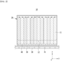
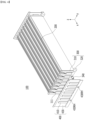
- Fig. 1 is a perspective view of a conventional battery module
- Fig. 2 is a cross-sectional view showing a cross section taken along the cutting line A-A' of Fig. 1
- Fig. 2 further shows a heat sink 30 arranged under the battery module 10 for convenience of explanation.
- the conventional battery module 10 includes a battery cell stack 12 formed by stacking a plurality of battery cells 11 and a module frame 20 that houses the battery cell stack 12.
- the battery cell 11 is a pouch-type battery cell
- the pouch-type battery cell forms a rectangular sheet structure.
- the battery module 10 Since a plurality of battery cells 11 are stacked, the battery module 10 generates a large amount of heat in a charge and discharge process.
- the battery module 10 including a pouch-type battery cell is cooled by bringing the ends of the battery cells 11 into indirect or direct contact with a heat sink 30 having a fixed position and size.
- the battery module 10 may include a thermal resin layer 40 located between the battery cell stack 12 and the bottom part of the module frame 20. Additionally, when the battery module 10 is mounted on the pack frame to form a battery pack, the heat transfer member 50 and the heat sink 30 may be located in sequence under the battery module 10.
- the heat transfer member 50 may be a heat dissipation pad, and a cooling flow path 31 through which a coolant such as cooling water flows may be formed inside the heat sink 30.
- the edges of the battery cells 11 stacked in one direction come into contact with the thermal resin layer 40, and the heat generated from the battery cells 11 is discharged to the outside of the battery module 10 through the thermal resin layer 40, the bottom part of the module frame 20, the heat transfer member 50, and the heat sink 30 in the stated order. That is, the conventional battery module 10 adopts a water-cooled type structure in which heat is discharged through the edges of the battery cells 11.
- Such a water-cooled type structure utilizing the edge of the battery cells 11 has a relatively simplified structure, but causes deterioration of cooling performance. Also, there is a risk of cracks occurring in the pouch case or the like of the battery cell 11 when high swelling of the battery cell 11 occurs.
- the battery cells 110 may cause a phenomenon in which the internal electrolyte decomposes to generate gas and the battery cell 110 swells in the process of repeated charging and discharging or in the initial charging process, that is, a swelling or breathing phenomenon.
- the thermal resin layer 40 has an adhesive property and thus, the battery cells 11 is fixed thereto. Therefore, when swelling of the battery cell 11 occurs in a direction parallel to the y-axis, high stress occurs at the edge of the battery cell 11, which may lead to cracking in the pouch case of the battery cell 11. Particularly, the more battery cells 11 located outside the battery cell stack 12, the greater the stress due to swelling, which results in a high risk of cracking.
- a battery module comprising: a plurality of battery cell groups including at least one battery cell and stacked along one direction; and a heat sink that cools the battery cell groups, wherein the battery cell includes electrode leads that protrudes in a direction perpendicular to the direction in which the battery cell groups are stacked, wherein the heat sink comprises cooling tubes interposed between the battery cell groups and a manifold connecting the cooling tubes, located in a direction in which the electrode leads protrude with reference to the battery cells and extending along the direction in which the battery cell groups are stacked, wherein a flow path is formed in the inside of the cooling tube and the manifold, so that a coolant flows along the inside of the cooling tube and the manifold, and wherein the cooling tube comes into contact with one surface of the battery cell group.
- the battery module may further comprise a busbar connected to the electrode lead, wherein an insulating member is located between the busbar and the manifold. One surface of the insulating member may come into contact with the busbar, and the other surface of the insulating member may come into contact with the manifold.
- the battery module may further comprise an insulating frame located in a direction in which the electrode lead protrudes with reference to the battery cell, wherein the busbar may be mounted on the insulating frame.
- the busbar may be mounted on the opposite surface of the surface facing the battery cell groups among the insulating frame, and the electrode lead may be bent after passing through a lead slit formed in the insulating frame, and be connected to the busbar.
- the insulating frame may be formed with an opening hole, and the busbar may be exposed toward the manifold through the opening hole.
- the busbar may extend from one side of the insulating frame to be exposed toward the manifold.
- the insulating member may be an insulating tape that has electrical insulation and adhesive properties.
- the battery module may further comprise a busbar connected to the electrode lead, wherein the busbar and the manifold may come into direct contact.
- the cooling tube may be in the form of a rectangular sheet, and the cooling tube may cover the whole of one surface of the battery cell group and contact the surface of the battery cell group.
- the manifold may have a cylindrical shape.
- the battery cell group may have a configuration in which at least one battery cell is wrapped in a wrapping member.
- the wrapping member may have electrical insulation properties.
- the battery cell group may have a configuration in which two or more battery cells are wrapped in a wrapping member, and a compression pad may be interposed in at least one of the two or more battery cells.
- the manifold may include a first manifold located on one side of the cooling tubes, and a second manifold located on the other side of the cooling tubes, and a circulation structure of the coolant may be formed in the first manifold, the cooling tubes, and the second manifold.
- An inflow part into which a coolant flows may be connected to a first part of the first manifold, and a discharge part through which the coolant is discharged may be connected to a second part of the first manifold, and the first part and the second part may be divided by a separation member.
- the coolant may sequentially flow through respective inside of the first part, the cooling tubes connected to the first part, the second manifold, the cooling tubes connected to the second part, and the second part.
- An inflow part into which a coolant flows may be connected to the first manifold, and a discharge part through which the coolant is discharged may be connected to the second manifold.
- the coolant may sequentially flow through respective inside of the first manifold, the cooling tubes, and the second manifold.
- a battery pack comprising: the above-mentioned battery module; a pack frame in which the battery module is housed; and vertical beams disposed on a bottom part of the pack frame so as to be perpendicular to one surface of the bottom part of the pack frame, wherein the battery module is disposed between the vertical beams.
- An adhesive member may be located between the battery module and the bottom part of the pack frame.
- the battery pack may further comprise an upper bracket that is located at an upper part of the battery module, extends along the direction in which the battery cell groups are stacked, and is fastened to the vertical beam.
- the battery module may further comprise a module frame that houses the battery cell groups and the heat sink.
- the module frame may be formed with a protruding module mounting part, and the module mounting part may be fastened to the vertical beam.
- the heat sink since the heat sink includes a cooling tube located between the battery cells, thus enabling surface cooling of the battery cells rather than the existing edge cooling structure, the battery module has increased cooling performance.
- the electrode lead portion of the battery cell is a portion in which heat generation is excessive in the battery cell, and the busbar connecting the electrode lead of the battery cell is configured to come into contact with the heat sink through an insulating member, thereby further improving the cooling performance of the battery module.
- planar it means when a target portion is viewed from the upper side
- cross-sectional it means when a target portion is viewed from the side of a cross section cut vertically.
- Fig. 3 is a perspective view showing a battery module 100 according to an embodiment of the present disclosure.
- Fig. 4 is an exploded perspective view which separates and shows the busbar assembly 400 from the battery module 100 of Fig. 3 .
- Fig. 5 is a perspective view which eliminates the busbar assembly 400 from the battery module 100 of Fig. 3 and shows only the battery cell group 200 and heat sink 300.
- the battery module 100 includes a plurality of battery cell groups 200 stacked along one direction; and a heat sink 300 that cools such battery cell groups 200.
- the battery cell group 200 includes at least one battery cell, wherein the battery cell includes electrode leads 111 and 112 that protrude in a direction perpendicular to the direction in which the battery cell groups 200 are stacked.
- Figs. 3 to 5 illustrate that the battery cell groups 200 are stacked along a direction parallel to the y-axis, and the electrode leads 111 and 112 of the battery cells protrude in both the x-axis direction and the -x-axis direction.
- the battery cell group 200 will be described in more detail below with reference to Figs. 6 to 8 .
- the heat sink 300 includes cooling tubes 310 interposed between the battery cell groups 200, and a manifold 320.
- the manifold 320 is located in the direction in which the electrode leads 111 and 112 protrude with reference to the battery cells, extends along the direction in which the battery cell groups 200 are stacked, and connects the cooling tubes 310.
- a flow path is formed in the inside of the cooling tube 310 and the manifold 320, so that a coolant flows along the inside of the cooling tube 310 and the manifold 320.
- the coolant may be cooling water as an example.
- the battery module 100 according to the present embodiment may have a water-cooled type cooling structure.
- the cooling tube 310 interposed between the battery cell groups 200 comes into contact with one surface of the battery cell group 200.
- the cooling tube 310 may be in the form of a rectangular sheet, and this cooling tube 310 covers the whole of one surface of the battery cell group 200, and may come into contact with one surface of the battery cell group 200. That is, the battery module 100 according to this embodiment has a surface cooling structure in which the cooling tube 310 through which a coolant flows inside comes into direct contact with one surface of the battery cell group 200, unlike a conventional battery module 10 having the edge cooling structure shown in Figs. 1 and 2 . In the case of a surface cooling structure, since the surface to be cooled is relatively much wider, cooling performance is greatly improved.
- the battery cells are not adhered or fixed to a thermal resin layer 40, high stress does not occur at the edges of the battery cells even if swelling occurs in the battery cells. In other words, it is possible to prevent the pouch case of the battery cell from cracking, thereby improving the structural safety of the battery module 100.
- Fig. 6 is a perspective view showing a battery cell group 200 included in the battery module 100 of Fig. 3 .
- Fig. 7 is a perspective view which eliminates the wrapping member 210 from the battery cell group 200 of Fig. 6 and shows only the battery cells 110 and compression pads 220.
- Fig. 8 is a plan view showing one of the battery cells 110 shown in Fig. 7 .
- the battery cell group 200 includes at least one battery cell 110. That is, one battery cell 110 can form one battery cell group 200, and a plurality of battery cells 110 may form one battery cell group 200.
- Figs. 6 and 7 show one an example in which two battery cells 110 are put together to form one battery cell group 200.
- the battery cell group 200 in the present disclosure may be a unit that divides an assembly of battery cells 110 disposed between cooling tubes 310. At least one battery cell 110 forms a battery cell group 200, and such battery cell groups 200 are stacked along one direction to form a battery cell stack.
- the battery cell 110 may be a pouch-type battery cell.
- the pouch-type battery cell may be formed by housing an electrode assembly in a pouch case made of a laminate sheet including a resin layer and a metal layer, and then joining the outer peripheral part of the pouch case.
- the battery cells 110 may be formed in a rectangular sheet structure.
- the battery cell 110 according to the present embodiment may have a structure in which two electrode leads 111 and 112 face each other and protrude from one end 114a and the other end 114b of a battery cell body 113, respectively.
- the battery cell 110 can be produced by joining both ends 114a and 114b of a cell case 114 and one side part 114c connecting them in a state in which an electrode assembly (not shown) is housed in a cell case 114.
- the battery cell 110 according to one embodiment of the present disclosure has a total of three sealing parts, the sealing parts have a structure that is sealed by a method such as fusion, and the remaining other side part 115 may be composed of a folded part.
- Such battery cells 110 form a battery cell group 200, and the battery cell groups 200 are stacked in an upright state along one direction to form a battery cell stack.
- the one direction that is stacked is a direction perpendicular to one surface of the battery cell body 113 of the battery cells 110, and in this specification, it corresponds to a direction parallel to the y-axis direction. Accordingly, the directions in which the electrode leads 111 and 112 protrude from the battery cells 110 correspond to the x-axis direction and -x-axis direction, which are directions perpendicular to the direction in which the battery cell groups 200 are stacked.
- the manifold 320 of the heat sink 300 may be located one by one in the x-axis direction and -x-axis direction, which are directions in which the electrode leads 111 and 112 protrude, respectively, with reference to the battery cell 110.
- the battery cell group 200 may have a configuration in which at least one battery cell 110 is wrapped in a wrapping member 210.
- Fig. 7 shows two battery cells 110 included in the battery cell group 200, and such battery cells 110 can be wrapped together with a wrapping member 210 to form a battery cell group 200 as shown in Fig. 6 .
- the wrapping member 210 may have electrical insulation properties.
- the wrapping member 210 may be an insulating tape with electrical insulation properties.
- two or more battery cells 110 within the battery cell group 200 may be wrapped with a wrapping member 210, and a compression pad 220 may be interposed at least at one place between the two or more battery cells 110.
- the compression pad 220 can be compressed to absorb the expansion of the battery cell 110.
- the material of the compression pad 220 is not particularly limited as long as it can be compressed to absorb expansion, but the material may include polyurethane (PU) material as an example.
- the battery cell group 200 corresponds to a unit that divides an assembly of battery cells 110 disposed between the cooling tubes 310 of the heat sink 300.
- the battery cells 110 are wound with the wrapping member 210 to form the battery cell group 200, thereby making assembly into the battery module easier and enhancing structural stability after assembly.
- the multiple battery cells 110 will not be properly fixed, thereby making assembly into a battery module difficult and impairing stability even after assembly.
- the wrapping member 210 has electrical insulation properties, it is possible to prevent the battery cells 110 from coming into contact with the leaked refrigerant and causing a short circuit.
- an adhesive may be applied to a partial area of the outer side portion of the wrapping member 210 corresponding to one surface of the battery cell group 200.
- an adhesive is applied to at least a partial area of the one surface of the battery cell group 200, so that the one surface of the battery cell group 200 and the cooling tube 310 can be adhered. This can improve ease of assembly and structural stability.
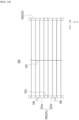
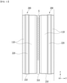
- Fig. 9 is a perspective view showing a heat sink 300 included in the battery module 100 of Figs. 3 and 4 .
- Fig. 10 is a plan view showing the heat sink 300 of Fig. 9 as viewed along the - z axis direction on the xy plane.
- Fig. 11 is a partial cross-sectional view showing a part of a cross section taken along the cutting line B-B' of Fig. 3 .
- the heat sink 300 includes cooling tubes 310 interposed between battery cell groups 200, and a manifold 320 connecting the cooling tubes 310.
- the manifold 320 is located in the direction in which the electrode leads 111 and 112 protrude with reference to the battery cell 110, extends along the direction in which the battery cell groups 200 are stacked, and connects the cooling tubes 310.
- a flow path is formed inside the cooling tube 310 and the manifold 320, so that a coolant flows along the inside of the cooling tube 310 and the manifold 320.
- the cooling tubes 310 and the manifold 320 may be in the form of a tube containing a metal material with excellent thermal conductivity in order to increase cooling performance.
- the cooling tube 310 interposed between the battery cell groups 200 comes into contact with one surface of the battery cell group 200.
- the cooling tube 310 may be in the form of a rectangular sheet, and may be located in an upright state between the battery cell groups 200.
- the cooling tube 310 covers the whole of one surface of the battery cell group 200 and may come into contact with the one surface of the battery cell group 200.
- the wrapping member 210 that wraps the battery cells 110 at the outermost side of the battery cell group 200 may come into contact with a sheet-shaped cooling tube 310.
- an adhesive is applied to at least a partial area of the one surface of the battery cell group 200, so that the one surface of the battery cell group 200 and the cooling tube 310 can be adhered.
- the coolant flows in the internal space S of the cooling tube 310 and cools the battery cell groups 200 on the periphery.
- the manifold 320 is connected to each of the cooling tubes 310, and the internal space of the manifold 320 and the internal space S of the cooling tube 310 communicate with each other, so that a coolant circulates.
- the manifold 320 may be cylindrical.
- the manifold 320 is shown as being connected to the lower end of the cooling tubes 310, the upper and lower portions of the manifold 320 are not particularly limited, and the manifold can also be located at the upper end of the cooling tubes 310.
- the manifold 320 may include a first manifold 321 located on one side of the cooling tubes 310, and a second manifold 322 located on the other side of the cooling tubes 310.
- the first manifold 321 may be located in the direction in which one electrode lead 111 protrudes
- the second manifold 322 may be located in a direction in which the other electrode lead 112 protrudes.
- the first manifold 321 and the second manifold 322 may be located on the opposite sides to each other in reference to the cooling tubes 310.
- a circulation structure of the coolant may be formed in the first manifold 321, the cooling tubes 310, and the second manifold 322.
- an inflow part 330 into which the coolant flows may be connected to the first part 321a of the first manifold 321
- a discharge part 340 through which the coolant is discharged may be connected to the second part 321b of the first manifold 321, wherein the first part 321a and the second part 321b may be divided by a separation member 321c.
- the first part 321a and the second part 321b are blocked by a separation member 321c, so that the connection between the inner space of the first part 321a and the inner space of the second part 321b can be cut off.
- the coolant that has flowed into the inflow part 330 may sequentially flow through respective inside of the first part 321a, the cooling tubes 310 connected to the first part 321a, the second manifold 322, the cooling tubes 310 connected to the second part 321b, and the second part 321b, and may finally be discharged through a discharge part 340 connected to the second part 321b.
- the inflow part 330 and the discharge part 340 are connected to a coolant circulation device (not shown) including a pump, etc., and the coolant flows along the above-mentioned circulation structure.
- the inflow part 330 and the discharge part 340 are located in the same direction, so that a coolant circulation device, including a pump, etc. can be provided on only one side of the battery pack. Accordingly, there is an advantage that the space inside the battery pack can be configured efficiently, and a complicated design of the coolant circulation device is not required.
- busbar assembly 400 according to the present embodiment will be described in detail.
- Fig. 12 is a perspective view showing an insulating frame 430 included in the battery module 100 of Fig. 3 .
- the battery module 100 may include a busbar assembly 400, wherein the busbar assembly 400 may include a busbar 410 connected to the electrode leads 111 and 112 of the battery cell 110, and an insulating frame 430 located in a direction in which the electrode leads 111 and 112 protrude with reference to the battery cell 110.
- the insulating frame 430 may be located on the same side as the manifold 320 of the heat sink 300. That is, the insulating frame 430 may be formed by a plurality of numbers and may be located on one side and the other side of the battery cell groups 200, respectively.
- the busbar 410 preferably includes a metal material that enables electrical connection.
- the insulating frame 430 preferably includes an electrically insulating material to prevent a short circuit from occurring due to contact with the battery cells 110 or the like.
- the insulating frame 430 may be a plastic injection-molded article.
- the busbar 410 may be mounted on the opposite surface of the surface facing the battery cell groups 200 among the insulating frame 430.
- the electrode leads 111 and 112 protruding from the battery cells 110 may be bent after passing through the lead slit 430S formed in the insulating frame 430, and be connected to the busbar 410. More specifically, one electrode lead 111 may pass through a lead slit 430S of the insulating frame 430 located on one side of the battery cell groups 200 and then be connected to the busbar 410, and the other electrode lead 112 may pass through a lead slit 430S of the insulating frame 430 located on the other side of the battery cell groups 200 and then be connected to the busbar 410.
- the connection method between the electrode leads 111 and 112 and the busbar 410 is not particularly limited, but weld-jointing may be performed as an example.
- the battery cells 110 may be electrically connected to each other in series or in parallel.
- a coolant hole 430RH may be provided in the insulating frame 430 so that the inflow part 330 and the discharge part 340 of the heat sink 300 penetrate therethrough.
- the insulating frame 430 may be mounted with a terminal busbar for connecting external power of the battery module 100 and a module connector for transmitting voltage and temperature sensing information.
- Fig. 13 is a partial cross-sectional view showing a part of a cross section taken along the cutting line C-C' of Fig. 3 .
- the busbar 410 and the manifold 320 of the heat sink 300 may come into contact with each other through the insulating member 420 located therebetween. That is, the insulating member 420 may be attached to the surface of the other portion, rather than the portion where the electrode leads 111 and 112 are connected among the busbar 410, and the busbar 410 may come into contact with the manifold 320 of the heat sink 300 through the surface to which the insulating member 420 is attached. One surface of the insulating member 420 may come into contact with the busbar 410, and the other surface of the insulating member 420 may come into contact with the manifold 320.
- the insulating frame 430 may formed with an opening hole 430H, and the busbars 410 may be exposed toward the manifold 320 of the heat sink 300 through the opening hole 430H, so that the busbar 410 and the manifold 320 can come into contact with each other via the insulating member 420.
- the busbar 410 is mounted on the opposite surface of the surface facing the battery cell groups 200 among the insulating frame 430.
- an opening hole 430H is formed in the insulating frame 430 so that the busbar 410 passes through this opening hole 430H and extends close to the manifold 320.
- the battery module 100 brings the busbar 410 into direct contact with the manifold 320 of the heat sink 300 through which a coolant flows, thereby realizing a direct cooling structure for the busbar 410 in which heat generation is excessive. Because a direct cooling structure for the busbar 410 is possible, this helps improve the overall cooling performance of the battery module, and the heat generated in the electrode leads 111 and 112 directly connected to the busbar 410 can also be easily discharged.
- the insulating member 420 may be an insulating tape that has electrical insulation and adhesive properties.
- the cooling tubes 310 and manifolds 320 included in the heat sink 300 may include a metal material. When the busbar 410 comes into contact with such manifolds 320, a short circuit may occur, and therefore, it is preferable to contact them with an insulating member 420 having electrical insulation and adhesive properties interposed therebetween.
- the busbar 410 can come into direct contact with the manifold 320 without the insulating member 420.
- Fig. 14 is a perspective view showing an insulating frame and busbar according to another embodiment of the present disclosure.
- a busbar 410 may be mounted on an insulating frame 430' according to another embodiment of the present disclosure.
- the electrode lead may be bent after passing through the lead slit 430S formed in the insulating frame 430', and be connected to the busbar 410. A detailed described will be omitted as it overlaps with the contents described above.
- the busbar 410 may extend from one side of the insulating frame 430' and be exposed toward the manifold of the heat sink. As shown in Fig. 14 , the busbar 410 may extend downward from the insulating frame 430'. Unlike the insulating frame 430 formed with an opening hole 430H shown in Figs. 12 and 13 , the insulating frame 430' in this embodiment may be shortened in height so that the busbar 410 is exposed toward the manifold.
- Fig. 15 is a plan view showing a heat sink according to another embodiment of the present disclosure when viewed along the -z axis direction on the xy plane.
- the heat sink 300' includes cooling tubes 310, and a manifold 320 connecting the cooling tubes 310.
- the manifold 320 may include a first manifold 321 located on one side of the cooling tubes 310, and a second manifold 322 located on the other side of the cooling tubes 310.
- a circulation structure of the coolant may be formed in the first manifold 321, the cooling tubes 310, and the second manifold 322. Specifically, an inflow part 330 into which a coolant flows may be connected to the first manifold 321, and a discharge part 340 through which a coolant is discharged may be connected to the second manifold 322.
- the coolant that has flowed into the inflow part 330 may sequentially flow through respective inside of the first manifold 321, the cooling tubes 310, and the second manifold 322, and may finally be discharged through a discharge part 340 connected to the second manifold 322.
- the inflow part 330 and the discharge part 340 are connected to a coolant circulation device (not shown) including a pump, etc., and the coolant flows along the circulation structure as mentioned above.
- the coolant inside the cooling tubes 310 flows in only one direction and its path is shortened, there is an advantage that the coolant can be circulated even with a relatively low pump pressure. Additionally, because the coolant flows in only one direction, there is an advantage that a uniform cooling effect can be achieved for each battery cell 110.
- Figs. 16 and 17 are a front view and a top view, respectively, of a battery pack according to an embodiment of the present disclosure. Specifically, in the battery pack 1000 including two battery modules 100 of Fig. 3 , the appearance that is viewed along the -x axis direction from the yz plane is shown in Fig. 16 , and the appearance that is viewed along the -z axis direction from the xy plane is shown in Fig. 17 .
- the battery pack 1000 includes a battery module 100, a pack frame 1100 in which the battery module 100 is housed, and vertical beams 1200 disposed on the bottom 1100F of the pack frame 1100 so as to be perpendicular to one side of the bottom 1100F of the pack frame 1100.
- the battery module 100 is disposed between the vertical beams 1200.
- the number of battery modules 100 provided in the battery pack 1000 is not particularly limited, and one or more battery modules 100 may be disposed.
- an adhesive member 1400 may be located between the battery module 100 and the bottom 1100F of the pack frame 1100.
- the battery module 100 may be fixed to the bottom 1100F of the pack frame 1100 through an adhesive member 1400 having adhesive properties.
- the battery module 100 according to the present embodiment does not have a configuration in which the battery cells 110 are housed in a specific frame, but may be mounted on the pack frame 1100 with the battery cell groups 200 and the heat sink 300 directly fixed to the adhesive member 1400.
- the battery pack 1000 may further include an upper bracket 1300 that is located at the upper part of the battery module 100, extends along the direction in which the battery cell groups 200 are stacked, and is fastened to the vertical beam 1200.
- the upper bracket 1300 may be assembled to the vertical beam 1200, and the method of assembling the upper bracket 1300 and the vertical beam 1200 is not particularly limited, and adhesive, weld-joining, bolt assembly or the like may be applied.
- the battery module 100 may be mounted and fixed on the pack frame 1100 through the vertical beam 1200 and the upper bracket 1300.
- the battery module 100 does not have a configuration of being housed in a separate frame and fixed to the pack frame as it is, but a configuration of being fixed by an adhesive member 1400 on a bottom part 1100F, a vertical beam 1200, an upper bracket 1300, and the like. Since it is not housed in a separate frame, it is possible to reduce the weight and volume as much as the frame and achieve a simplified structure, which is effective in improving space utilization and increasing battery capacity.
- the battery module 100 since it is not housed in a frame, the battery module 100 does not have sufficient structural rigidity to prevent swelling of the battery cells 110. Therefore, in the present embodiment, it has been designed such that by bringing the side surfaces of the battery module 100 into close contact with the vertical beams 1200, the vertical beam 1200 can compensate for the structural rigidity against swelling of the battery cells 110.
- a pad 1500 for tolerance compensation may be disposed at least at one place between the battery module 100 and the vertical beam 1200 or between the battery module 100 and the upper bracket 1300.
- Fig. 18 is a perspective view showing a battery pack according to another embodiment of the present disclosure.
- the battery pack 1000 includes a battery module 100, a pack frame 1100 in which the battery module 100 is housed, and vertical beams 1200 disposed on the bottom part 1100F of the pack frame 1100 so as to be perpendicular to one side of the bottom 1100F of the pack frame 1100, wherein the battery module 100 is disposed between the vertical beams 1200.
- the battery module 100 may further include a module frame 500 that houses battery cell groups 200 and a heat sink 300.
- the module frame 500 includes a bottom surface and side surfaces 510 extending upward from both sides facing the bottom surface, and may have an open top.
- the side surface 510 of the module frame 500 may be formed with a module mounting part 500M protruding in a direction perpendicular to the side surface 510, and the module mounting part 500M may be fastened to the vertical beam 1200.
- a through hole may be formed in the module mounting part 500M. After the bolt member passes through such a through hole, bolt assembly may be performed in which the bolt member is fastened to the vertical beam 1200.
- the battery pack 1000 is configured such that the side surface of the battery module 100 is brought into close contact with the vertical beams 1200, and the module mounting portion 500M of the module frame 500 is fastened to the vertical beam 1200, thereby designing so as to complement the structural rigidity against swelling of the battery cell 110 and to ensure that the battery module 100 is firmly fixed to the pack frame 1100.
- the one or more battery modules according to embodiments of the present disclosure described above can be mounted together with various control and protection systems such as a BMS (battery management system), a BDU(battery disconnect unit), and a cooling system to form a battery pack.
- BMS battery management system
- BDU battery disconnect unit
- the battery module or the battery pack can be applied to various devices. Specifically, it can be applied to vehicle means such as an electric bike, an electric vehicle, and a hybrid electric vehicle, or an ESS (Energy Storage System) and may be applied to various devices capable of using a secondary battery, without being limited thereto.
- vehicle means such as an electric bike, an electric vehicle, and a hybrid electric vehicle, or an ESS (Energy Storage System) and may be applied to various devices capable of using a secondary battery, without being limited thereto.
- ESS Electronicgy Storage System
Landscapes
- Chemical & Material Sciences (AREA)
- Chemical Kinetics & Catalysis (AREA)
- Electrochemistry (AREA)
- General Chemical & Material Sciences (AREA)
- Engineering & Computer Science (AREA)
- Manufacturing & Machinery (AREA)
- Battery Mounting, Suspending (AREA)
- Secondary Cells (AREA)
- Connection Of Batteries Or Terminals (AREA)
Abstract
Description
- This application claims priority to and the benefit of
Korean Patent Application No. 10-2022-0106189, filed on August 24, 2022 - The present disclosure relates to a battery module and a battery pack including the same, and more particularly, to a battery module that enables direct cooling and thus has improved cooling performance, and a battery pack including the same.
- In modern society, as portable devices such as a mobile phone, a notebook computer, a camcorder and a digital camera has been daily used, the development of technologies in the fields related to mobile devices as described above has been activated. In addition, chargeable/dischargeable secondary batteries are used as a power source for an electric vehicle (EV), a hybrid electric vehicle (HEV), a plug-in hybrid electric vehicle (P-HEV) and the like, in an attempt to solve air pollution and the like caused by existing gasoline vehicles using fossil fuel. Therefore, the demand for development of the secondary battery is growing.
- Generally, the lithium secondary battery may be classified into a can-type secondary battery in which the electrode assembly is mounted in a metal can, and a pouch-type secondary battery in which the electrode assembly is mounted in a pouch of an aluminum laminate sheet, depending on the shape of the exterior material.
- In the case of a secondary battery used for small-sized devices, two to three battery cells are disposed, but in the case of a secondary battery used for a medium- and large-sized device such as automobiles, a battery module in which a plurality of battery cells are electrically connected is used. In such a battery module, a plurality of battery cells are connected to each other in series or parallel to form a cell assembly, thereby improving capacity and output. Further, one or more battery modules can be mounted together with various control and protection systems such as a BDU (Battery Disconnect Unit), a BMS (battery management system) and a cooling system to form a battery pack.
- When a secondary battery is heated over a proper temperature, the performance of the secondary battery may deteriorate, and in the worst case, there is also a risk of an explosion or ignition. In particular, a plurality of secondary batteries, that is, a battery module or a battery pack having battery cells can accumulate the heat emitted from the plurality of battery cells in a narrow space, which may raise the temperature of the battery module quickly and severely. In other words, a battery module including a large number of battery cells, and a battery pack equipped with such a battery module can obtain high output, but it is not easy to remove heat generated from the battery cells during charging and discharging. When the heat dissipation of the battery cell is not properly performed, deterioration of the battery cells is accelerated, the lifespan is shortened, and the possibility of explosion or ignition increases.
- Moreover, if a medium- or large-sized battery module is included in a battery pack for a vehicle, the battery module may be frequently exposed to direct sunlight and may be placed under high-temperature conditions, for example, in summer or in a desert. Therefore, when configuring a battery module or a battery pack, it may be very important to ensure stable and effective cooling performance. Cooling methods of battery modules or battery packs can be largely classified into a water cooling method using a coolant such as cooling water and an air cooling method using cooling wind. Among them, water-cooled type cooling has excellent cooling performance and can effectively cool high heat generated from large-capacity battery modules or battery packs.
-
Fig. 1 is a perspective view of a conventional battery module, andFig. 2 is a cross-sectional view showing a cross section taken along the cutting line A-A' ofFig. 1 . However,Fig. 2 further shows aheat sink 30 arranged under thebattery module 10 for convenience of explanation. - Referring to
Figs. 1 and2 , theconventional battery module 10 includes abattery cell stack 12 formed by stacking a plurality ofbattery cells 11 and amodule frame 20 that houses thebattery cell stack 12. At this time, thebattery cell 11 is a pouch-type battery cell, and the pouch-type battery cell forms a rectangular sheet structure. - Since a plurality of
battery cells 11 are stacked, thebattery module 10 generates a large amount of heat in a charge and discharge process. Thebattery module 10 including a pouch-type battery cell is cooled by bringing the ends of thebattery cells 11 into indirect or direct contact with aheat sink 30 having a fixed position and size. - Specifically, the
battery module 10 may include athermal resin layer 40 located between thebattery cell stack 12 and the bottom part of themodule frame 20. Additionally, when thebattery module 10 is mounted on the pack frame to form a battery pack, theheat transfer member 50 and theheat sink 30 may be located in sequence under thebattery module 10. Theheat transfer member 50 may be a heat dissipation pad, and acooling flow path 31 through which a coolant such as cooling water flows may be formed inside theheat sink 30. The edges of thebattery cells 11 stacked in one direction come into contact with thethermal resin layer 40, and the heat generated from thebattery cells 11 is discharged to the outside of thebattery module 10 through thethermal resin layer 40, the bottom part of themodule frame 20, theheat transfer member 50, and the heat sink 30 in the stated order. That is, theconventional battery module 10 adopts a water-cooled type structure in which heat is discharged through the edges of thebattery cells 11. - Such a water-cooled type structure utilizing the edge of the
battery cells 11 has a relatively simplified structure, but causes deterioration of cooling performance. Also, there is a risk of cracks occurring in the pouch case or the like of thebattery cell 11 when high swelling of thebattery cell 11 occurs. Specifically, thebattery cells 110 may cause a phenomenon in which the internal electrolyte decomposes to generate gas and thebattery cell 110 swells in the process of repeated charging and discharging or in the initial charging process, that is, a swelling or breathing phenomenon. - As the capacity of the battery cell increases, the degree of swelling also increases greatly, and the number of battery cells applied to the battery module tends to increase gradually. Therefore, controlling the swelling of the battery cells inside battery modules has become an important issue.
- At this time, referring to
Fig. 2 again, generally, thethermal resin layer 40 has an adhesive property and thus, thebattery cells 11 is fixed thereto. Therefore, when swelling of thebattery cell 11 occurs in a direction parallel to the y-axis, high stress occurs at the edge of thebattery cell 11, which may lead to cracking in the pouch case of thebattery cell 11. Particularly, themore battery cells 11 located outside thebattery cell stack 12, the greater the stress due to swelling, which results in a high risk of cracking. - In order to realize high-capacity battery modules and battery packs in the future, Pure Si cells, all-solid-state batteries, and high-SiO-content cells can be applied as pouch battery cells. For such battery cells, the degree of swelling is greater.
- When the conventional water cooling method utilizing the edge part is applied to a battery module including battery cells having a high degree of swelling, there is a high risk of cracks occurring in the battery cell, and excessive stress acts, which can impair the structural safety of the battery module.
- Accordingly, there is a demand for a battery module having a novel cooling structure that can minimize structural damages generated in the battery cell even if they include battery cells exhibiting high swelling characteristics.
- It is an object of the present disclosure to provide a battery module that enables direct cooling for each busbar that connects the battery cells and their electrode leads, and a battery pack including the same.
- However, the technical problems to be solved by embodiments of the present disclosure are not limited to the above-described problems, and can be variously expanded within the scope of the technical idea included in the present disclosure.
- According to one embodiment of the present disclosure, there is provided a battery module comprising: a plurality of battery cell groups including at least one battery cell and stacked along one direction; and a heat sink that cools the battery cell groups, wherein the battery cell includes electrode leads that protrudes in a direction perpendicular to the direction in which the battery cell groups are stacked, wherein the heat sink comprises cooling tubes interposed between the battery cell groups and a manifold connecting the cooling tubes, located in a direction in which the electrode leads protrude with reference to the battery cells and extending along the direction in which the battery cell groups are stacked, wherein a flow path is formed in the inside of the cooling tube and the manifold, so that a coolant flows along the inside of the cooling tube and the manifold, and wherein the cooling tube comes into contact with one surface of the battery cell group.
- The battery module may further comprise a busbar connected to the electrode lead, wherein an insulating member is located between the busbar and the manifold. One surface of the insulating member may come into contact with the busbar, and the other surface of the insulating member may come into contact with the manifold.
- The battery module may further comprise an insulating frame located in a direction in which the electrode lead protrudes with reference to the battery cell, wherein the busbar may be mounted on the insulating frame.
- The busbar may be mounted on the opposite surface of the surface facing the battery cell groups among the insulating frame, and the electrode lead may be bent after passing through a lead slit formed in the insulating frame, and be connected to the busbar.
- The insulating frame may be formed with an opening hole, and the busbar may be exposed toward the manifold through the opening hole.
- The busbar may extend from one side of the insulating frame to be exposed toward the manifold.
- The insulating member may be an insulating tape that has electrical insulation and adhesive properties.
- The battery module may further comprise a busbar connected to the electrode lead, wherein the busbar and the manifold may come into direct contact.
- The cooling tube may be in the form of a rectangular sheet, and the cooling tube may cover the whole of one surface of the battery cell group and contact the surface of the battery cell group.
- The manifold may have a cylindrical shape.
- The battery cell group may have a configuration in which at least one battery cell is wrapped in a wrapping member.
- The wrapping member may have electrical insulation properties.
- The battery cell group may have a configuration in which two or more battery cells are wrapped in a wrapping member, and a compression pad may be interposed in at least one of the two or more battery cells.
- The manifold may include a first manifold located on one side of the cooling tubes, and a second manifold located on the other side of the cooling tubes, and a circulation structure of the coolant may be formed in the first manifold, the cooling tubes, and the second manifold.
- An inflow part into which a coolant flows may be connected to a first part of the first manifold, and a discharge part through which the coolant is discharged may be connected to a second part of the first manifold, and the first part and the second part may be divided by a separation member. The coolant may sequentially flow through respective inside of the first part, the cooling tubes connected to the first part, the second manifold, the cooling tubes connected to the second part, and the second part.
- An inflow part into which a coolant flows may be connected to the first manifold, and a discharge part through which the coolant is discharged may be connected to the second manifold. The coolant may sequentially flow through respective inside of the first manifold, the cooling tubes, and the second manifold.
- According to another embodiment of the present disclosure, there is provided a battery pack comprising: the above-mentioned battery module; a pack frame in which the battery module is housed; and vertical beams disposed on a bottom part of the pack frame so as to be perpendicular to one surface of the bottom part of the pack frame, wherein the battery module is disposed between the vertical beams.
- An adhesive member may be located between the battery module and the bottom part of the pack frame.
- The battery pack may further comprise an upper bracket that is located at an upper part of the battery module, extends along the direction in which the battery cell groups are stacked, and is fastened to the vertical beam.
- The battery module may further comprise a module frame that houses the battery cell groups and the heat sink. The module frame may be formed with a protruding module mounting part, and the module mounting part may be fastened to the vertical beam.
- According to the embodiments of the present disclosure, since the heat sink includes a cooling tube located between the battery cells, thus enabling surface cooling of the battery cells rather than the existing edge cooling structure, the battery module has increased cooling performance.
- In addition, the electrode lead portion of the battery cell is a portion in which heat generation is excessive in the battery cell, and the busbar connecting the electrode lead of the battery cell is configured to come into contact with the heat sink through an insulating member, thereby further improving the cooling performance of the battery module.
- The effects of the present disclosure are not limited to the effects mentioned above and additional other effects not described above will be clearly understood from the description of the appended claims by those skilled in the art.
-
-
Fig. 1 is a perspective view of a conventional battery module; -
Fig. 2 is a cross-sectional view showing a cross section taken along the cutting line A-A' ofFig. 1 ; -
Fig. 3 is a perspective view showing a battery module according to an embodiment of the present disclosure; -
Fig. 4 is an exploded perspective view which separates and shows the busbar assembly from the battery module ofFig. 3 ; -
Fig. 5 is a perspective view which eliminates the busbar assembly from the battery module ofFig. 3 and shows only the battery cell group and heat sink; -
Fig. 6 is a perspective view showing a battery cell group included in the battery module ofFig. 3 ; -
Fig. 7 is a perspective view which eliminates the wrapping member from the battery cell group ofFig. 6 and shows only the battery cells and compression pads; -
Fig. 8 is a plan view showing one of the battery cells shown inFig. 7 ; -
Fig. 9 is a perspective view showing a heat sink included in the battery module ofFigs. 3 and4 ; -
Fig. 10 is a plan view showing the heat sink ofFig. 9 as viewed along the -z axis direction on the xy plane; -
Fig. 11 is a partial cross-sectional view showing a part of a cross section taken along the cutting line B-B' ofFig. 3 ; -
Fig. 12 is a perspective view showing an insulating frame included in the battery module ofFig. 3 ; -
Fig. 13 is a partial cross-sectional view showing a part of a cross section taken along the cutting line C-C' ofFig. 3 ; -
Fig. 14 is a perspective view showing an insulating frame and busbar according to another embodiment of the present disclosure; -
Fig. 15 is a plan view showing a heat sink according to another embodiment of the present disclosure when viewed along the -z axis direction on the xy plane; -
Figs. 16 and17 are a front view and a top view, respectively, of a battery pack according to an embodiment of the present disclosure; and -
Fig. 18 is a perspective view showing a battery pack according to another embodiment of the present disclosure. - Hereinafter, various embodiments of the present disclosure will be described in detail with reference to the accompanying drawings so that those skilled in the art can easily carry out them. The present disclosure may be modified in various different ways, and is not limited to the embodiments set forth herein.
- Portions that are irrelevant to the description will be omitted to clearly describe the present disclosure, and same reference numerals designate same or like elements throughout the description.
- Further, in the drawings, the size and thickness of each element are arbitrarily illustrated for convenience of description, and the present disclosure is not necessarily limited to those illustrated in the drawings. In the drawings, the thickness of layers, regions, etc. are exaggerated for clarity. In the drawings, for convenience of description, the thicknesses of a part and an area are exaggerated.
- Further, it will be understood that when an element such as a layer, film, region, or plate is referred to as being "on" or "above" another element, it can be directly on the other element or intervening elements may also be present. In contrast, when an element is referred to as being "directly on" another element, it means that other intervening elements are not present. Further, a certain part being located "above" or "on" a reference portion means the certain part being located above or below the reference portion and does not particularly mean the certain part "above" or "on" toward an opposite direction of gravity.
- Further, throughout the description, when a portion is referred to as "including" or "comprising" a certain component, it means that the portion can further include other components, without excluding the other components, unless otherwise stated.
- Further, throughout the description, when it is referred to as "planar", it means when a target portion is viewed from the upper side, and when it is referred to as "cross-sectional", it means when a target portion is viewed from the side of a cross section cut vertically.
-
Fig. 3 is a perspective view showing abattery module 100 according to an embodiment of the present disclosure.Fig. 4 is an exploded perspective view which separates and shows thebusbar assembly 400 from thebattery module 100 ofFig. 3 .Fig. 5 is a perspective view which eliminates thebusbar assembly 400 from thebattery module 100 ofFig. 3 and shows only thebattery cell group 200 andheat sink 300. - Referring to
Figs. 3 to 5 , thebattery module 100 according to an embodiment of the present disclosure includes a plurality ofbattery cell groups 200 stacked along one direction; and aheat sink 300 that cools suchbattery cell groups 200. - The
battery cell group 200 includes at least one battery cell, wherein the battery cell includes electrode leads 111 and 112 that protrude in a direction perpendicular to the direction in which thebattery cell groups 200 are stacked.Figs. 3 to 5 illustrate that thebattery cell groups 200 are stacked along a direction parallel to the y-axis, and the electrode leads 111 and 112 of the battery cells protrude in both the x-axis direction and the -x-axis direction. Thebattery cell group 200 will be described in more detail below with reference toFigs. 6 to 8 . - The
heat sink 300 includes coolingtubes 310 interposed between thebattery cell groups 200, and amanifold 320. The manifold 320 is located in the direction in which the electrode leads 111 and 112 protrude with reference to the battery cells, extends along the direction in which thebattery cell groups 200 are stacked, and connects the coolingtubes 310. A flow path is formed in the inside of thecooling tube 310 and the manifold 320, so that a coolant flows along the inside of thecooling tube 310 and themanifold 320. The coolant may be cooling water as an example. Thebattery module 100 according to the present embodiment may have a water-cooled type cooling structure. - Further, the cooling
tube 310 interposed between thebattery cell groups 200 comes into contact with one surface of thebattery cell group 200. The coolingtube 310 may be in the form of a rectangular sheet, and thiscooling tube 310 covers the whole of one surface of thebattery cell group 200, and may come into contact with one surface of thebattery cell group 200. That is, thebattery module 100 according to this embodiment has a surface cooling structure in which thecooling tube 310 through which a coolant flows inside comes into direct contact with one surface of thebattery cell group 200, unlike aconventional battery module 10 having the edge cooling structure shown inFigs. 1 and2 . In the case of a surface cooling structure, since the surface to be cooled is relatively much wider, cooling performance is greatly improved. In addition, unlike theconventional battery module 10 with an edge cooling structure, since the battery cells are not adhered or fixed to athermal resin layer 40, high stress does not occur at the edges of the battery cells even if swelling occurs in the battery cells. In other words, it is possible to prevent the pouch case of the battery cell from cracking, thereby improving the structural safety of thebattery module 100. - Next, referring to
Figs. 6 to 8 , thebattery cell group 200 according to this embodiment will be described in detail. -
Fig. 6 is a perspective view showing abattery cell group 200 included in thebattery module 100 ofFig. 3 .Fig. 7 is a perspective view which eliminates the wrappingmember 210 from thebattery cell group 200 ofFig. 6 and shows only thebattery cells 110 andcompression pads 220.Fig. 8 is a plan view showing one of thebattery cells 110 shown inFig. 7 . - Referring to
Figs. 6 to 8 together withFig. 5 , thebattery cell group 200 includes at least onebattery cell 110. That is, onebattery cell 110 can form onebattery cell group 200, and a plurality ofbattery cells 110 may form onebattery cell group 200.Figs. 6 and7 show one an example in which twobattery cells 110 are put together to form onebattery cell group 200. - The
battery cell group 200 in the present disclosure may be a unit that divides an assembly ofbattery cells 110 disposed betweencooling tubes 310. At least onebattery cell 110 forms abattery cell group 200, and suchbattery cell groups 200 are stacked along one direction to form a battery cell stack. - The
battery cell 110 according to the present embodiment may be a pouch-type battery cell. The pouch-type battery cell may be formed by housing an electrode assembly in a pouch case made of a laminate sheet including a resin layer and a metal layer, and then joining the outer peripheral part of the pouch case. As shown inFigs. 7 and8 , thebattery cells 110 may be formed in a rectangular sheet structure. Specifically, thebattery cell 110 according to the present embodiment may have a structure in which two electrode leads 111 and 112 face each other and protrude from oneend 114a and theother end 114b of abattery cell body 113, respectively. Thebattery cell 110 can be produced by joining bothends cell case 114 and oneside part 114c connecting them in a state in which an electrode assembly (not shown) is housed in acell case 114. In other words, thebattery cell 110 according to one embodiment of the present disclosure has a total of three sealing parts, the sealing parts have a structure that is sealed by a method such as fusion, and the remainingother side part 115 may be composed of a folded part. -
Such battery cells 110 form abattery cell group 200, and thebattery cell groups 200 are stacked in an upright state along one direction to form a battery cell stack. The one direction that is stacked is a direction perpendicular to one surface of thebattery cell body 113 of thebattery cells 110, and in this specification, it corresponds to a direction parallel to the y-axis direction. Accordingly, the directions in which the electrode leads 111 and 112 protrude from thebattery cells 110 correspond to the x-axis direction and -x-axis direction, which are directions perpendicular to the direction in which thebattery cell groups 200 are stacked. Further, as described above, themanifold 320 of theheat sink 300 may be located one by one in the x-axis direction and -x-axis direction, which are directions in which the electrode leads 111 and 112 protrude, respectively, with reference to thebattery cell 110. - On the other hand, the
battery cell group 200 according to the present embodiment may have a configuration in which at least onebattery cell 110 is wrapped in a wrappingmember 210. As an example,Fig. 7 shows twobattery cells 110 included in thebattery cell group 200, andsuch battery cells 110 can be wrapped together with a wrappingmember 210 to form abattery cell group 200 as shown inFig. 6 . The wrappingmember 210 may have electrical insulation properties. As an example, the wrappingmember 210 may be an insulating tape with electrical insulation properties. - Further, two or
more battery cells 110 within thebattery cell group 200 may be wrapped with a wrappingmember 210, and acompression pad 220 may be interposed at least at one place between the two ormore battery cells 110. When thebattery cell 110 expands, thecompression pad 220 can be compressed to absorb the expansion of thebattery cell 110. The material of thecompression pad 220 is not particularly limited as long as it can be compressed to absorb expansion, but the material may include polyurethane (PU) material as an example. - In the
battery module 100 according to the present embodiment, thebattery cell group 200 corresponds to a unit that divides an assembly ofbattery cells 110 disposed between the coolingtubes 310 of theheat sink 300. When thebattery cells 110 are placed between the coolingtubes 310, thebattery cells 110 are wound with the wrappingmember 210 to form thebattery cell group 200, thereby making assembly into the battery module easier and enhancing structural stability after assembly. Whenmultiple battery cells 110 are placed between the coolingtubes 310, unless they are wound with the wrappingmember 210 to form abattery cell group 200, themultiple battery cells 110 will not be properly fixed, thereby making assembly into a battery module difficult and impairing stability even after assembly. Additionally, since the wrappingmember 210 has electrical insulation properties, it is possible to prevent thebattery cells 110 from coming into contact with the leaked refrigerant and causing a short circuit. - Furthermore, an adhesive may be applied to a partial area of the outer side portion of the wrapping
member 210 corresponding to one surface of thebattery cell group 200. When the one surface of thebattery cell group 200 comes into contact with the coolingtube 310, an adhesive is applied to at least a partial area of the one surface of thebattery cell group 200, so that the one surface of thebattery cell group 200 and thecooling tube 310 can be adhered. This can improve ease of assembly and structural stability. - Next, with reference to
Figs. 9 to 11 , the heat sink and the coolant circulation structure inside the heat sink according to this embodiment will be described in detail. -
Fig. 9 is a perspective view showing aheat sink 300 included in thebattery module 100 ofFigs. 3 and4 .Fig. 10 is a plan view showing theheat sink 300 ofFig. 9 as viewed along the - z axis direction on the xy plane.Fig. 11 is a partial cross-sectional view showing a part of a cross section taken along the cutting line B-B' ofFig. 3 . - As mentioned above, the
heat sink 300 according to the present embodiment includes coolingtubes 310 interposed betweenbattery cell groups 200, and a manifold 320 connecting the coolingtubes 310. The manifold 320 is located in the direction in which the electrode leads 111 and 112 protrude with reference to thebattery cell 110, extends along the direction in which thebattery cell groups 200 are stacked, and connects the coolingtubes 310. A flow path is formed inside the coolingtube 310 and the manifold 320, so that a coolant flows along the inside of thecooling tube 310 and themanifold 320. The coolingtubes 310 and the manifold 320 may be in the form of a tube containing a metal material with excellent thermal conductivity in order to increase cooling performance. - The cooling
tube 310 interposed between thebattery cell groups 200 comes into contact with one surface of thebattery cell group 200. The coolingtube 310 may be in the form of a rectangular sheet, and may be located in an upright state between thebattery cell groups 200. The coolingtube 310 covers the whole of one surface of thebattery cell group 200 and may come into contact with the one surface of thebattery cell group 200. The wrappingmember 210 that wraps thebattery cells 110 at the outermost side of thebattery cell group 200 may come into contact with a sheet-shapedcooling tube 310. - Additionally, as mentioned above, an adhesive is applied to at least a partial area of the one surface of the
battery cell group 200, so that the one surface of thebattery cell group 200 and thecooling tube 310 can be adhered. As shown inFig. 11 , the coolant flows in the internal space S of thecooling tube 310 and cools thebattery cell groups 200 on the periphery. - On the other hand, the manifold 320 is connected to each of the cooling
tubes 310, and the internal space of the manifold 320 and the internal space S of thecooling tube 310 communicate with each other, so that a coolant circulates. As an example, the manifold 320 may be cylindrical. Although the manifold 320 is shown as being connected to the lower end of the coolingtubes 310, the upper and lower portions of the manifold 320 are not particularly limited, and the manifold can also be located at the upper end of the coolingtubes 310. - The manifold 320 according to this embodiment may include a
first manifold 321 located on one side of the coolingtubes 310, and asecond manifold 322 located on the other side of the coolingtubes 310. In the electrode leads 111 and 112 protruding from thebattery cell 110 in mutually opposite directions, thefirst manifold 321 may be located in the direction in which oneelectrode lead 111 protrudes, and thesecond manifold 322 may be located in a direction in which theother electrode lead 112 protrudes. In other words, thefirst manifold 321 and thesecond manifold 322 may be located on the opposite sides to each other in reference to thecooling tubes 310. - In the
heat sink 300 according to the present embodiment, a circulation structure of the coolant may be formed in thefirst manifold 321, the coolingtubes 310, and thesecond manifold 322. Specifically, aninflow part 330 into which the coolant flows may be connected to thefirst part 321a of thefirst manifold 321, and adischarge part 340 through which the coolant is discharged may be connected to thesecond part 321b of thefirst manifold 321, wherein thefirst part 321a and thesecond part 321b may be divided by aseparation member 321c. Thefirst part 321a and thesecond part 321b are blocked by aseparation member 321c, so that the connection between the inner space of thefirst part 321a and the inner space of thesecond part 321b can be cut off. - The coolant that has flowed into the
inflow part 330 may sequentially flow through respective inside of thefirst part 321a, the coolingtubes 310 connected to thefirst part 321a, thesecond manifold 322, the coolingtubes 310 connected to thesecond part 321b, and thesecond part 321b, and may finally be discharged through adischarge part 340 connected to thesecond part 321b. Theinflow part 330 and thedischarge part 340 are connected to a coolant circulation device (not shown) including a pump, etc., and the coolant flows along the above-mentioned circulation structure. - In the case of the
heat sink 300 according to the present embodiment, when thebattery module 100 is housed in the pack frame to form a battery pack, theinflow part 330 and thedischarge part 340 are located in the same direction, so that a coolant circulation device, including a pump, etc. can be provided on only one side of the battery pack. Accordingly, there is an advantage that the space inside the battery pack can be configured efficiently, and a complicated design of the coolant circulation device is not required. - Next, the
busbar assembly 400 according to the present embodiment will be described in detail. -
Fig. 12 is a perspective view showing an insulatingframe 430 included in thebattery module 100 ofFig. 3 . - Referring to
Figs. 3 ,4 , and12 together, thebattery module 100 according to the present embodiment may include abusbar assembly 400, wherein thebusbar assembly 400 may include abusbar 410 connected to the electrode leads 111 and 112 of thebattery cell 110, and an insulatingframe 430 located in a direction in which the electrode leads 111 and 112 protrude with reference to thebattery cell 110. - When the
battery cell 110 or thebattery cell group 200 is used as a reference, the insulatingframe 430 may be located on the same side as themanifold 320 of theheat sink 300. That is, the insulatingframe 430 may be formed by a plurality of numbers and may be located on one side and the other side of thebattery cell groups 200, respectively. - The
busbar 410 preferably includes a metal material that enables electrical connection. The insulatingframe 430 preferably includes an electrically insulating material to prevent a short circuit from occurring due to contact with thebattery cells 110 or the like. As an example, the insulatingframe 430 may be a plastic injection-molded article. - The
busbar 410 may be mounted on the opposite surface of the surface facing thebattery cell groups 200 among the insulatingframe 430. The electrode leads 111 and 112 protruding from thebattery cells 110 may be bent after passing through the lead slit 430S formed in the insulatingframe 430, and be connected to thebusbar 410. More specifically, oneelectrode lead 111 may pass through alead slit 430S of the insulatingframe 430 located on one side of thebattery cell groups 200 and then be connected to thebusbar 410, and theother electrode lead 112 may pass through alead slit 430S of the insulatingframe 430 located on the other side of thebattery cell groups 200 and then be connected to thebusbar 410. The connection method between the electrode leads 111 and 112 and thebusbar 410 is not particularly limited, but weld-jointing may be performed as an example. - In the same manner as mentioned above, the
battery cells 110 may be electrically connected to each other in series or in parallel. - Meanwhile, a coolant hole 430RH may be provided in the insulating
frame 430 so that theinflow part 330 and thedischarge part 340 of theheat sink 300 penetrate therethrough. In addition, although not specifically illustrated, the insulatingframe 430 may be mounted with a terminal busbar for connecting external power of thebattery module 100 and a module connector for transmitting voltage and temperature sensing information. - On the other hand,
Fig. 13 is a partial cross-sectional view showing a part of a cross section taken along the cutting line C-C' ofFig. 3 . - Referring to
Figs. 3 ,4 ,12 , and13 together, thebusbar 410 and themanifold 320 of theheat sink 300 may come into contact with each other through the insulatingmember 420 located therebetween. That is, the insulatingmember 420 may be attached to the surface of the other portion, rather than the portion where the electrode leads 111 and 112 are connected among thebusbar 410, and thebusbar 410 may come into contact with themanifold 320 of theheat sink 300 through the surface to which the insulatingmember 420 is attached. One surface of the insulatingmember 420 may come into contact with thebusbar 410, and the other surface of the insulatingmember 420 may come into contact with themanifold 320. - As an example, the insulating
frame 430 may formed with anopening hole 430H, and thebusbars 410 may be exposed toward themanifold 320 of theheat sink 300 through theopening hole 430H, so that thebusbar 410 and the manifold 320 can come into contact with each other via the insulatingmember 420. In order to prevent thebusbar 410 from contacting other portion of thebattery cell 110 except the portion of the electrode leads 111 and 112, thebusbar 410 is mounted on the opposite surface of the surface facing thebattery cell groups 200 among the insulatingframe 430. At this time, in order to form a direct cooling structure for thebusbar 410, anopening hole 430H is formed in the insulatingframe 430 so that thebusbar 410 passes through thisopening hole 430H and extends close to themanifold 320. - When charge and discharge of the
battery cell 110 are repeated, heat is generated in thebattery cell 110, and it is important to control this heat. If the heat dissipation of the battery cell is not performed properly, deterioration of the battery cell is facilitated, which shortens its lifespan, and increases the possibility of explosion or ignition. Particularly, among thebattery cells 110, a great amount of heat is generated in the electrode leads 111 and 112 and bothends battery cell case 114 adjacent to the electrode leads 111 and 112 (seeFig. 8 ). Accordingly, a great amount of heat is also generated in thebusbar 410, which is a portion directly connected to the electrode leads 111 and 112 within thebattery module 100. - The
battery module 100 according to the present embodiment brings thebusbar 410 into direct contact with themanifold 320 of theheat sink 300 through which a coolant flows, thereby realizing a direct cooling structure for thebusbar 410 in which heat generation is excessive. Because a direct cooling structure for thebusbar 410 is possible, this helps improve the overall cooling performance of the battery module, and the heat generated in the electrode leads 111 and 112 directly connected to thebusbar 410 can also be easily discharged. - On the other hand, the insulating
member 420 may be an insulating tape that has electrical insulation and adhesive properties. In order to increase the thermal conductivity of theheat sink 300, the coolingtubes 310 andmanifolds 320 included in theheat sink 300 may include a metal material. When thebusbar 410 comes into contact withsuch manifolds 320, a short circuit may occur, and therefore, it is preferable to contact them with an insulatingmember 420 having electrical insulation and adhesive properties interposed therebetween. - In another embodiment of the present disclosure, if the manifold 320 includes an electrically insulating material rather than a metal material, the
busbar 410 can come into direct contact with the manifold 320 without the insulatingmember 420. -
Fig. 14 is a perspective view showing an insulating frame and busbar according to another embodiment of the present disclosure. - Referring to
Fig. 14 , abusbar 410 may be mounted on an insulating frame 430' according to another embodiment of the present disclosure. The electrode lead may be bent after passing through the lead slit 430S formed in the insulating frame 430', and be connected to thebusbar 410. A detailed described will be omitted as it overlaps with the contents described above. - In the present embodiment, the
busbar 410 may extend from one side of the insulating frame 430' and be exposed toward the manifold of the heat sink. As shown inFig. 14 , thebusbar 410 may extend downward from the insulating frame 430'. Unlike the insulatingframe 430 formed with anopening hole 430H shown inFigs. 12 and13 , the insulating frame 430' in this embodiment may be shortened in height so that thebusbar 410 is exposed toward the manifold. - On the other hand,
Fig. 15 is a plan view showing a heat sink according to another embodiment of the present disclosure when viewed along the -z axis direction on the xy plane. - Referring to
Fig. 15 , the heat sink 300' according to another embodiment of the present disclosure includes coolingtubes 310, and a manifold 320 connecting the coolingtubes 310. Further, the manifold 320 may include afirst manifold 321 located on one side of the coolingtubes 310, and asecond manifold 322 located on the other side of the coolingtubes 310. - In the heat sink 300' according to the present embodiment, a circulation structure of the coolant may be formed in the
first manifold 321, the coolingtubes 310, and thesecond manifold 322. Specifically, aninflow part 330 into which a coolant flows may be connected to thefirst manifold 321, and adischarge part 340 through which a coolant is discharged may be connected to thesecond manifold 322. - The coolant that has flowed into the
inflow part 330 may sequentially flow through respective inside of thefirst manifold 321, the coolingtubes 310, and thesecond manifold 322, and may finally be discharged through adischarge part 340 connected to thesecond manifold 322. Theinflow part 330 and thedischarge part 340 are connected to a coolant circulation device (not shown) including a pump, etc., and the coolant flows along the circulation structure as mentioned above. - In the case of the heat sink 300' according to the present embodiment, since the coolant inside the cooling
tubes 310 flows in only one direction and its path is shortened, there is an advantage that the coolant can be circulated even with a relatively low pump pressure. Additionally, because the coolant flows in only one direction, there is an advantage that a uniform cooling effect can be achieved for eachbattery cell 110. - Next, the battery pack including the battery module according to the present embodiment will be described in detail.
-
Figs. 16 and17 are a front view and a top view, respectively, of a battery pack according to an embodiment of the present disclosure. Specifically, in thebattery pack 1000 including twobattery modules 100 ofFig. 3 , the appearance that is viewed along the -x axis direction from the yz plane is shown inFig. 16 , and the appearance that is viewed along the -z axis direction from the xy plane is shown inFig. 17 . - Referring to
Figs. 3 ,16 and17 , thebattery pack 1000 according to an embodiment of the present disclosure includes abattery module 100, apack frame 1100 in which thebattery module 100 is housed, andvertical beams 1200 disposed on the bottom 1100F of thepack frame 1100 so as to be perpendicular to one side of the bottom 1100F of thepack frame 1100. Thebattery module 100 is disposed between thevertical beams 1200. The number ofbattery modules 100 provided in thebattery pack 1000 is not particularly limited, and one ormore battery modules 100 may be disposed. - At this time, an
adhesive member 1400 may be located between thebattery module 100 and the bottom 1100F of thepack frame 1100. Thebattery module 100 may be fixed to the bottom 1100F of thepack frame 1100 through anadhesive member 1400 having adhesive properties. Thebattery module 100 according to the present embodiment does not have a configuration in which thebattery cells 110 are housed in a specific frame, but may be mounted on thepack frame 1100 with thebattery cell groups 200 and theheat sink 300 directly fixed to theadhesive member 1400. - In addition, the
battery pack 1000 may further include anupper bracket 1300 that is located at the upper part of thebattery module 100, extends along the direction in which thebattery cell groups 200 are stacked, and is fastened to thevertical beam 1200. Theupper bracket 1300 may be assembled to thevertical beam 1200, and the method of assembling theupper bracket 1300 and thevertical beam 1200 is not particularly limited, and adhesive, weld-joining, bolt assembly or the like may be applied. Thebattery module 100 may be mounted and fixed on thepack frame 1100 through thevertical beam 1200 and theupper bracket 1300. - Taken together, the
battery module 100 according to the present embodiment does not have a configuration of being housed in a separate frame and fixed to the pack frame as it is, but a configuration of being fixed by anadhesive member 1400 on abottom part 1100F, avertical beam 1200, anupper bracket 1300, and the like. Since it is not housed in a separate frame, it is possible to reduce the weight and volume as much as the frame and achieve a simplified structure, which is effective in improving space utilization and increasing battery capacity. - However, since it is not housed in a frame, the
battery module 100 does not have sufficient structural rigidity to prevent swelling of thebattery cells 110. Therefore, in the present embodiment, it has been designed such that by bringing the side surfaces of thebattery module 100 into close contact with thevertical beams 1200, thevertical beam 1200 can compensate for the structural rigidity against swelling of thebattery cells 110. - On the other hand, a
pad 1500 for tolerance compensation may be disposed at least at one place between thebattery module 100 and thevertical beam 1200 or between thebattery module 100 and theupper bracket 1300. -
Fig. 18 is a perspective view showing a battery pack according to another embodiment of the present disclosure. - Referring to
Fig. 18 , thebattery pack 1000 according to another embodiment of the present disclosure includes abattery module 100, apack frame 1100 in which thebattery module 100 is housed, andvertical beams 1200 disposed on thebottom part 1100F of thepack frame 1100 so as to be perpendicular to one side of the bottom 1100F of thepack frame 1100, wherein thebattery module 100 is disposed between thevertical beams 1200. - The
battery module 100 may further include amodule frame 500 that housesbattery cell groups 200 and aheat sink 300. Themodule frame 500 includes a bottom surface andside surfaces 510 extending upward from both sides facing the bottom surface, and may have an open top. - The
side surface 510 of themodule frame 500 may be formed with amodule mounting part 500M protruding in a direction perpendicular to theside surface 510, and themodule mounting part 500M may be fastened to thevertical beam 1200. As an example, a through hole may be formed in themodule mounting part 500M. After the bolt member passes through such a through hole, bolt assembly may be performed in which the bolt member is fastened to thevertical beam 1200. - The
battery pack 1000 according to the present embodiment is configured such that the side surface of thebattery module 100 is brought into close contact with thevertical beams 1200, and themodule mounting portion 500M of themodule frame 500 is fastened to thevertical beam 1200, thereby designing so as to complement the structural rigidity against swelling of thebattery cell 110 and to ensure that thebattery module 100 is firmly fixed to thepack frame 1100. - The terms representing directions such as the front side, the rear side, the left side, the right side, the upper side, and the lower side have been used in the present embodiment, but the terms used are provided simply for convenience of description and may become different according to the position of an object, the position of an observer, or the like.
- The one or more battery modules according to embodiments of the present disclosure described above can be mounted together with various control and protection systems such as a BMS (battery management system), a BDU(battery disconnect unit), and a cooling system to form a battery pack.
- The battery module or the battery pack can be applied to various devices. Specifically, it can be applied to vehicle means such as an electric bike, an electric vehicle, and a hybrid electric vehicle, or an ESS (Energy Storage System) and may be applied to various devices capable of using a secondary battery, without being limited thereto.
- Although the invention has been described in detail with reference to preferred embodiments thereof, the scope of the present disclosure is not limited thereto, and various modifications and improvements can be made by those skilled in the art using the basic concepts of the present disclosure, which are defined in the appended claims, which also falls within the scope of the present disclosure.
-
- 100:
- battery module
- 110:
- battery cell
- 200:
- battery cell group
- 300:
- heat sink
- 310:
- cooling tube
- 320:
- manifold
- 400:
- busbar assembly
- 410:
- busbar
Claims (20)
- A battery module comprising:a plurality of battery cell groups including at least one battery cell and stacked along one direction; anda heat sink that cools the battery cell groups,wherein the battery cell comprises electrode leads that protrudes in a direction perpendicular to the direction in which the battery cell groups are stacked,wherein the heat sink comprises cooling tubes interposed between the battery cell groups, and a manifold connecting the cooling tubes, located in a direction in which the electrode leads protrude with reference to the battery cells and extending along the direction in which the battery cell groups are stackedwherein a flow path is formed in the inside of the cooling tube and the manifold, so that a coolant flows along the inside of the cooling tube and the manifold, andwherein the cooling tube comes into contact with one surface of the battery cell group.
- The battery module according to claim 1,further comprising a busbar connected to the electrode lead,wherein an insulating member is located between the busbar and the manifold, andone surface of the insulating member comes into contact with the busbar, and the other surface of the insulating member comes into contact with the manifold.
- The battery module according to claim 2,further comprising an insulating frame located in a direction in which the electrode lead protrudes with reference to the battery cell,wherein the busbar is mounted on the insulating frame.
- The battery module according to claim 3, wherein:the busbar is mounted on the opposite surface of the surface facing the battery cell groups among the insulating frame, andthe electrode lead is bent after passing through a lead slit formed in the insulating frame, and is connected to the busbar.
- The battery module according to claim 4, wherein:the insulating frame is formed with an opening hole, andthe busbar is exposed toward the manifold through the opening hole.
- The battery module according to claim 4, wherein:
the busbar extends from one side of the insulating frame to be exposed toward the manifold. - The battery module according to claim 2, wherein:
the insulating member is an insulating tape that has electrical insulation and adhesive properties. - The battery module according to claim 1,further comprising a busbar connected to the electrode lead,wherein the busbar and the manifold come into direct contact.
- The battery module according to claim 1, wherein:the cooling tube is in the form of a rectangular sheet, andthe cooling tube covers the whole of one surface of the battery cell group and contacts the surface of the battery cell group.
- The battery module according to claim 1, wherein:
the manifold has a cylindrical shape. - The battery module according to claim 1, wherein:
the battery cell group has a configuration in which at least one battery cell is wrapped in a wrapping member. - The battery module according to claim 11, wherein:
the wrapping member has electrical insulation properties. - The battery module according to claim 1, wherein:
the battery cell group has a configuration in which two or more battery cells are wrapped in a wrapping member, and a compression pad is interposed in at least one of the two or more battery cells. - The battery module according to claim 1, wherein:the manifold includes a first manifold located on one side of the cooling tubes, and a second manifold located on the other side of the cooling tubes, anda circulation structure of the coolant is formed in the first manifold, the cooling tubes, and the second manifold.
- The battery module according to claim 14, wherein:an inflow part into which the coolant flows is connected to a first part of the first manifold, and a discharge part through which the coolant is discharged is connected to a second part of the first manifold,the first part and the second part are divided by a separation member, andthe coolant sequentially flows through respective inside of the first part, the cooling tubes connected to the first part, the second manifold, the cooling tubes connected to the second part, and the second part.
- The battery module according to claim 14, wherein:an inflow part into which the coolant flows is connected to the first manifold, and a discharge part through which the coolant is discharged is connected to the second manifold, andthe coolant sequentially flows through respective inside of the first manifold, the cooling tubes, and the second manifold.
- A battery pack comprising:the battery module according to claim 1;a pack frame in which the battery module is housed; andvertical beams disposed on a bottom part of the pack frame so as to be perpendicular to one surface of the bottom part of the pack frame,wherein the battery module is disposed between the vertical beams.
- The battery pack according to claim 17, wherein:
an adhesive member is located between the battery module and the bottom part of the pack frame. - The battery pack according to claim 17,
further comprising an upper bracket that is located at an upper part of the battery module, extends along the direction in which the battery cell groups are stacked, and is fastened to the vertical beam. - The battery pack according to claim 17, wherein:the battery module further comprises a module frame that houses the battery cell groups and the heat sink,the module frame is formed with a protruding module mounting part, andthe module mounting part is fastened to the vertical beam.
Applications Claiming Priority (2)
| Application Number | Priority Date | Filing Date | Title |
|---|---|---|---|
| KR1020220106189A KR20240028583A (en) | 2022-08-24 | 2022-08-24 | Battery module and battery pack including the same |
| PCT/KR2023/010386 WO2024043540A1 (en) | 2022-08-24 | 2023-07-19 | Battery module and battery pack comprising same |
Publications (2)
| Publication Number | Publication Date |
|---|---|
| EP4428990A1 true EP4428990A1 (en) | 2024-09-11 |
| EP4428990A4 EP4428990A4 (en) | 2025-10-01 |
Family
ID=90013635
Family Applications (1)
| Application Number | Title | Priority Date | Filing Date |
|---|---|---|---|
| EP23857576.5A Pending EP4428990A4 (en) | 2022-08-24 | 2023-07-19 | BATTERY MODULE AND BATTERY PACK |
Country Status (6)
| Country | Link |
|---|---|
| US (1) | US20250364631A1 (en) |
| EP (1) | EP4428990A4 (en) |
| JP (1) | JP7744089B2 (en) |
| KR (1) | KR20240028583A (en) |
| CN (1) | CN118339703A (en) |
| WO (1) | WO2024043540A1 (en) |
Families Citing this family (2)
| Publication number | Priority date | Publication date | Assignee | Title |
|---|---|---|---|---|
| WO2025192891A1 (en) * | 2024-03-13 | 2025-09-18 | 주식회사 엘지에너지솔루션 | Battery assembly and battery pack including same |
| KR20260036687A (en) * | 2024-09-09 | 2026-03-17 | 주식회사 엘지에너지솔루션 | Battery device |
Family Cites Families (24)
| Publication number | Priority date | Publication date | Assignee | Title |
|---|---|---|---|---|
| WO2007102672A1 (en) * | 2006-03-06 | 2007-09-13 | Lg Chem, Ltd. | Battery module |
| JP2012180876A (en) * | 2011-02-28 | 2012-09-20 | Nifco Inc | Tubular structure and battery temperature control system using the same |
| KR101750066B1 (en) * | 2011-12-02 | 2017-06-23 | 에스케이이노베이션 주식회사 | Water-cooled type secondary battery |
| KR101528007B1 (en) * | 2012-09-17 | 2015-06-10 | 한라비스테온공조 주식회사 | Battery cooling apparatus for vehicle |
| KR101779945B1 (en) * | 2015-04-01 | 2017-09-19 | 주식회사 엘지화학 | Battery Module Comprising Cooling member with Cooling Tube |
| KR102005488B1 (en) * | 2015-06-16 | 2019-10-01 | 주식회사 엘지화학 | Cell Cover for secondary battery and battery module including the same |
| KR102150679B1 (en) * | 2018-03-13 | 2020-09-01 | 주식회사 엘지화학 | Battery module, battery pack comprising the battery module and vehicle comprising the battery pack |
| KR102277035B1 (en) * | 2018-03-21 | 2021-07-13 | 주식회사 엘지에너지솔루션 | Battery module, battery pack comprising the battery module and vehicle comprising the battery pack |
| JP7466108B2 (en) * | 2018-07-31 | 2024-04-12 | パナソニックIpマネジメント株式会社 | Battery module and battery pack |
| WO2020027299A1 (en) * | 2018-08-03 | 2020-02-06 | 三井化学株式会社 | Cooling plate and battery structure |
| KR102424400B1 (en) * | 2018-09-13 | 2022-07-22 | 주식회사 엘지에너지솔루션 | Battery Module Having Heat-Shrinkable Tube |
| KR102204302B1 (en) * | 2018-09-13 | 2021-01-15 | 주식회사 엘지화학 | Battery module, battery pack comprising the battery module and vehicle comprising the battery pack |
| KR102358425B1 (en) * | 2018-09-18 | 2022-02-03 | 주식회사 엘지에너지솔루션 | Battery module |
| JP7022343B2 (en) * | 2018-11-06 | 2022-02-18 | トヨタ自動車株式会社 | Batteries assembled |
| KR102762534B1 (en) * | 2019-03-04 | 2025-02-03 | 주식회사 엘지에너지솔루션 | A battery module comprising a pad composite having swelling absorption and heat shielding function, a battery pack and a vehicle comprising the same |
| JP7322159B2 (en) * | 2019-03-07 | 2023-08-07 | 寧徳時代新能源科技股▲分▼有限公司 | Battery module manufacturing method and battery pack manufacturing method |
| KR102716908B1 (en) * | 2019-03-21 | 2024-10-11 | 주식회사 엘지에너지솔루션 | A battery module having a module housing of a thin plate type and a battery pack including the same |
| KR102771554B1 (en) * | 2019-08-07 | 2025-02-20 | 주식회사 엘지에너지솔루션 | Battery pack that incorporates a battery module and a rigid beam and employs a reverse assembly |
| EP3852188B1 (en) * | 2019-11-19 | 2025-07-09 | Contemporary Amperex Technology (Hong Kong) Limited | Battery pack and transport equipment |
| US11276573B2 (en) | 2019-12-04 | 2022-03-15 | Applied Materials, Inc. | Methods of forming high boron-content hard mask materials |
| KR102954302B1 (en) * | 2020-07-22 | 2026-04-16 | 주식회사 엘지에너지솔루션 | Battery pack and vehicle comprising the battery pack |
| JP7585460B2 (en) * | 2020-08-13 | 2024-11-18 | エルジー エナジー ソリューション リミテッド | Battery module having a cooling structure using insulating coolant, battery pack including the same, and automobile |
| KR20220081028A (en) * | 2020-12-08 | 2022-06-15 | 주식회사 엘지에너지솔루션 | Battery module and battery pack including the same |
| KR102807493B1 (en) * | 2021-01-11 | 2025-05-13 | 주식회사 엘지에너지솔루션 | Battery module and battery pack including the same |
-
2022
- 2022-08-24 KR KR1020220106189A patent/KR20240028583A/en active Pending
-
2023
- 2023-07-19 CN CN202380014847.2A patent/CN118339703A/en active Pending
- 2023-07-19 JP JP2024529829A patent/JP7744089B2/en active Active
- 2023-07-19 WO PCT/KR2023/010386 patent/WO2024043540A1/en not_active Ceased
- 2023-07-19 US US18/712,841 patent/US20250364631A1/en active Pending
- 2023-07-19 EP EP23857576.5A patent/EP4428990A4/en active Pending
Also Published As
| Publication number | Publication date |
|---|---|
| KR20240028583A (en) | 2024-03-05 |
| EP4428990A4 (en) | 2025-10-01 |
| US20250364631A1 (en) | 2025-11-27 |
| CN118339703A (en) | 2024-07-12 |
| JP7744089B2 (en) | 2025-09-25 |
| WO2024043540A1 (en) | 2024-02-29 |
| JP2024543106A (en) | 2024-11-19 |
Similar Documents
| Publication | Publication Date | Title |
|---|---|---|
| US20240170790A1 (en) | Battery module and battery pack including the same | |
| US12230819B2 (en) | Battery module and battery pack including the same | |
| US12548822B2 (en) | Battery pack and device including the same | |
| US20220393270A1 (en) | Battery module and battery pack including same | |
| CN114388871B (en) | Battery pack and device comprising same | |
| EP4210154A1 (en) | Battery pack and device comprising same | |
| EP4228061B1 (en) | Battery pack and device including the same | |
| US20250364631A1 (en) | Battery Module and Battery Pack Including the Same | |
| EP4266457B1 (en) | Battery module and battery pack including the same | |
| EP4181275B1 (en) | Battery module and battery pack including same | |
| US12592424B2 (en) | Battery module and battery pack including the same | |
| EP4391156A1 (en) | Battery pack and device comprising same | |
| EP4020672B1 (en) | Battery pack and device including same | |
| US20250279503A1 (en) | Battery module and battery pack including the same | |
| EP4181292A1 (en) | Battery module and battery pack including same | |
| US20240113357A1 (en) | Battery pack and device including the same | |
| EP4175020A1 (en) | Battery module and battery pack including same | |
| KR20230133228A (en) | Battery pack and device including the same | |
| EP4715983A1 (en) | Battery module and battery pack including same | |
| JP7864265B2 (en) | Battery module and battery pack containing the same | |
| US20240396144A1 (en) | Battery Module and Battery Pack Including the Same | |
| KR20250128006A (en) | Battery module and battery pack including the same |
Legal Events
| Date | Code | Title | Description |
|---|---|---|---|
| STAA | Information on the status of an ep patent application or granted ep patent |
Free format text: STATUS: THE INTERNATIONAL PUBLICATION HAS BEEN MADE |
|
| PUAI | Public reference made under article 153(3) epc to a published international application that has entered the european phase |
Free format text: ORIGINAL CODE: 0009012 |
|
| STAA | Information on the status of an ep patent application or granted ep patent |
Free format text: STATUS: REQUEST FOR EXAMINATION WAS MADE |
|
| 17P | Request for examination filed |
Effective date: 20240604 |
|
| AK | Designated contracting states |
Kind code of ref document: A1 Designated state(s): AL AT BE BG CH CY CZ DE DK EE ES FI FR GB GR HR HU IE IS IT LI LT LU LV MC ME MK MT NL NO PL PT RO RS SE SI SK SM TR |
|
| RIC1 | Information provided on ipc code assigned before grant |
Ipc: H01M 50/502 20210101ALI20250402BHEP Ipc: H01M 50/588 20210101ALI20250402BHEP Ipc: H01M 50/595 20210101ALI20250402BHEP Ipc: H01M 50/24 20210101ALI20250402BHEP Ipc: H01M 10/6568 20140101ALI20250402BHEP Ipc: H01M 10/647 20140101ALI20250402BHEP Ipc: H01M 10/613 20140101ALI20250402BHEP Ipc: H01M 10/6556 20140101ALI20250402BHEP Ipc: H01M 10/6553 20140101ALI20250402BHEP Ipc: H01M 10/6551 20140101AFI20250402BHEP |
|
| A4 | Supplementary search report drawn up and despatched |
Effective date: 20250903 |
|
| RIC1 | Information provided on ipc code assigned before grant |
Ipc: H01M 10/6551 20140101AFI20250828BHEP Ipc: H01M 10/6553 20140101ALI20250828BHEP Ipc: H01M 10/6556 20140101ALI20250828BHEP Ipc: H01M 10/613 20140101ALI20250828BHEP Ipc: H01M 10/647 20140101ALI20250828BHEP Ipc: H01M 10/6568 20140101ALI20250828BHEP Ipc: H01M 50/24 20210101ALI20250828BHEP Ipc: H01M 50/595 20210101ALI20250828BHEP Ipc: H01M 50/588 20210101ALI20250828BHEP Ipc: H01M 50/502 20210101ALI20250828BHEP |
|
| DAV | Request for validation of the european patent (deleted) | ||
| DAX | Request for extension of the european patent (deleted) |